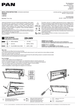
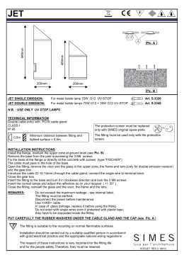
serie
series
4
IN
TE
RM
ED
I
E
TE
RM
IN
AL
LO
SI
NG
O
REV. 11.12
O
A
Z
fig. 1
ASTRO ECLISSE PLANET LED
V
I
serie ASTRO
QUAD ECLISSE PLANET LED
Avvertenze generali
•
•
•
•
•
•
•
•
•
L’apparecchio è costruito a regola d’arte, e la sua durata elettrica sarà più efficiente se esso sarà usato correttamente.
Leggere attentamente le avvertenze che seguono in quanto forniscono importanti indicazioni riguardanti la sicurezza di installazione d’uso e di manutenzione.
Dopo aver tolto l’imballaggio assicurarsi dell’integrità dell’apparecchio. In caso di dubbio non utilizzare l’apparecchio e rivolgersi al proprio rivenditore.
Gli elementi dell’imballaggio (sacchetti in plastica, ecc.) non devono essere lasciati alla portata dei bambini in quanto potenziali fonti di pericolo.
Prima di collegare l’apparecchio accertarsi che i dati di targa siano rispondenti a quelli della rete di distribuzione elettrica alla quale l’apparecchio sarà collegato
(L’etichetta con i dati di targa è situata all’interno dell’apparecchio stesso).
Questo apparecchio dovrà essere destinato solo all’uso per il quale è stato espressamente concepito e cioè per l’illuminazione di ambienti chiusi e non umidi, con
temperatura ambiente max. 35°C (95°F).
Prima di effettuare qualsiasi operazione di pulizia o di manutenzione, disinserire l’apparecchio dalla rete di alimentazione elettrica spegnendo l’interruttore
dell’impianto, e in caso di guasto rivolgersi solamente a personale professionalmente qualificato.
Il mancato rispetto di quanto sopra può compromettere la sicurezza dell’apparecchio.
Il costruttore non può essere considerato responsabile per eventuali danni derivanti da usi impropri, erronei ed irragionevoli.
General warnings
•
•
•
•
•
•
•
•
•
Istruzioni per l’installazione
1. Per plafoniere singole o terminali [fig. 1], posare l’apparecchio [A] su di un piano d’appoggio e applicare il blocca cavo sul foro esterno [Z]
sul profilo in alluminio in prossimità dell’angolo. Questo è il foro d’entrata per l’alimentazione esterna che va collegata al morsetto.
2. Per il collegamento della linea [fig. 1] tra terminale/intermedio e intermedio/intermedio posare l’apparecchio [A] su di un piano d’appoggio
ed effettuare il ponticello (cavallotto) tra una apparecchio e l’altro.
3. Realizzati i collegamenti elettrici, montare lo schermo con telaio, facendolo inserire nella plafoniera prima da un lato (se presente, quello più
lungo), e spingere l’altro all’interno della plafoniera facendo leva sul telaio dello schermo [S], in prossimità dei due angoli [fig. 2], previo aver
collegato il cavo di messa a terra tra il telaio dello schermo e l’apparecchio [A]; montare l’ottica inserendola nella plafoniera prima puntandola
sul lato lungo e successivamente incastrandola a scatto sul lato apposto, facendo particolare attenzione all’utilizzo dei guanti in dotazione e alla cura
nell’operazione, collegare il cavo di messa a terra tra l’ottica e l’apparecchio [A].
4. Dopo aver montato la sospensione e/o l’attacco a plafone (come da istruzioni sotto riportate o inserite nel kit fornito separatamente alla plafoniera),
inserire nelle canaline [V], i relativi dispositivi di ancoraggio [fig. 1].
Installation Instructions
Table 1 - Distance between holes for fixing the fittings to the ceiling or on the wall
3 strisce da 4 led (plafoniera quadrata piccola)
4 strisce da 7 led (plafoniera quadrata grande)
2 strisce da 14 led (plafoniera rettangolare)
Square small fitting - 12 leds
Square big fitting - 28 leds
Rectangular fitting - 28 leds
220 x 254 mm
420 x 454 mm
minimo 600 mm massimo 1100 mm
=
=
=
220 x 254 mm
420 x 454 mm
minimum 600 mm maximum 1,100 mm
MOUNTING OF LINEAR OR CORNER JOINT
1. Insert the alignment plates [P] (should the same not already be mounted), into the guides on the inside of the profile as in figure [fig. 4], inserting
the alignment plates only half-way, on the side indicated by the white dot (the side marked with the white dot will snap into the guides, therefore,
use a hammer to finish the insertion operation, while the projecting part that remains shall only have to be inserted into the corresponding guides
of the other module, only as an alignment).
2. Remove the top cover or screen in order to reach the two fixing holes [Q] (holes located on the lamp support brackets), for the closure of the two
modules in line [fig. 4], then proceed with the insertion of the screws between the two support brackets of the two modules to unite and tighten
with the nuts (included).
3. Mount the lower cover, linear joint cover, subsequent to the connection of the grounding wire.
4. Proceed with the electrical connection between the two fittings, as described in point 2 of the "Installation instructions".
5. Mount the optics, screen, prismatic or cell-like kit, performing the operations described in point 3 of the "Installation Instructions" and re-mountthe
upper cover and shield.
Important warnings
Avvertenze importanti
•
•
•
•
1. Identify the inter-axis fixing holes [tab. 1] and mark on the surface where the fitting is to be fixed. The inter-axis for square fitting are fixed. The
inter-axis for rectangular fitting can be positioned between a minimum and maximum quota, given that the ceiling connections along the ceiling
lamp are mobile, while the inter-axis [N], has a width of 100 mm (fig. 5).
2. For square version, fix the fitting directly to the ceiling or to the wall, with screws or screw anchors (not included), through the fixing holes. For
3. rectangular version, fix the connections [L] [fig. 5] to the ceiling or to the wall , with screws or screw anchors (not included), through the holes [N].
For rectangular version only, slide the stirrup in PA6 [M], into the duct [V] present on the top part of the module [A] [fig. 1 and 5], up to the chosen
4. inter-axis.
Unite the two parts of the ceiling connections [L and M], tightening them with the screws included [fig. 5].
Tabella 1 - Interasse fori per il fissaggio a plafone
MONTAGGIO GIUNTO LINEARE O ANGOLO
•
•
bient temperature of 35°C (95°F).
Before carrying out any cleaning or maintenance operations, disconnect the fitting from the electricity network supply by switching off the system’s switch,
and if a fault occurs, contact professionally qualified personnel only.
Failure to observe the above may jeopardise the safety of the fitting.
The manufacturer cannot be considered liable for any damages deriving from improper, wrong and unreasonable use of the fitting.
ASSEMBLY WITH CEILING AND WALL CONNECTION
1. Inserire le piastrine di allineamento [P] (qualora non siano già montate), nelle guide all’interno del profilo come in figura [fig. 4], inserendo solo
metà della lunghezza della piastrina di allineamento, dal lato indicato dal puntino bianco (il lato contrassegnato dal puntino bianco si incastrerà
nelle guide, pertanto utilizzare un martello per compiere l’operazione d’inserimento, mentre la parte che resterà sporgente, sarà solo da infilare nelle
guide corrispondenti sull’altro modulo, solo come allineamento).
2. Togliere il coperchio o lo schermo superiore, per raggiungere i due fori di fissaggio [Q] (fori siti sulle squadrette porta lampade), per la chiusura
dei due moduli in linea [fig. 4], quindi procedere con l’inserimento delle viti tra le due squadrette dei due moduli da unire e chiuderle con i dadi
(in dotazione).
3. Montare il coperchio inferiore, copri giunto lineare, previo collegamento della messa a terra.
4. Procedere al collegamento elettrico tra i due apparecchi, come descritto al punto 2 delle “Istruzioni per l’istallazione”.
5. Montare ottica, schermo, kit prismato o alveolare, compiendo le operazioni descritte al punto 3 delle “Istruzioni per l’istallazione” e rimontare il
coperchio o lo schermo superiore.
•
The fitting is manufactured in a workmanlike fashion, and its electric life will be more efficient if it is used correctly.
Read the following warnings carefully since they contain important information about installation, usage and maintenance safety.
After removing the packaging, make sure that the fitting is intact. If in doubt, do not use the fitting and contact your retailer.
Packaging materials (plastic bags, etc.) must not be left within the reach of children, as they are a potential source of danger.
Before connecting the fitting to the power supply make sure that the rating corresponds to the rating of the electricity network to which the fitting will be connected
(The rating label is located on the cover of the fitting itself).
This fitting must be used exclusively for the purpose for which it is explicitly designed, i.e. for lighting closed and not damp environments, with a maximumam-
1. For single or terminal [fig. 1], place the fitting [A] on a flat surface and apply the wire lock on the external hole [Z] of the aluminium profile
close to the corner. This is the entry hole for the external supply cable which must be connected to the terminal block.
2. For the connection of the line [fig. 1], between head/middle and middle/middle, place the fitting [A] on a flat surface and make the bridge
between one fitting and the other.
3. Once the electrical connections have been completed, mount the framed shield, entering it into the ceiling lamp from one side first (if present,
the longer side), and push the other one into the ceiling lamp making leverage on the frame of the shield [S], close to the two corners [fig. 2],
subject to having connected the grounding wire between the frame of the shield and the fitting [A]; mount the optics inserting them into the
ceiling lamp laying them along the longer side and subsequently snapping them into place on the opposite side, paying particular attention to the
use of the gloves provided and to the operation, connect the grounding wire between the optics and the fitting [A].
4. After mounting the suspension and/or attachment to the ceiling lamp (according to the instructions below or in the kit supplied separately from the
ceiling lamp), insert into the ducts [V] the relative anchor devices [fig. 1].
MONTAGGIO CON ATTACCO A SOFFITTO E A PARETE
1. Rilevare l’interasse dei fori di fissaggio dalla tabella [tab. 1] e segnare sulla superficie dove dovrà essere fissato l’apparecchio. Tale interasse è
fisso per le versioni quadrate. Per le versioni rettangolari, l’interasse è posizionabile tra una quota minima ed una massima, essendo gli attacchi a
soffitto mobili sulla plafoniera per la sua lunghezza, mentre l’interasse [N], la sua larghezza, è di 100 mm (fig. 5).
2. Per le versioni quadrate, fissare l’apparecchio direttamente a plafone o a parete, mediante viti o tasselli (non in dotazione), attraverso i fori di
fissaggio. Per le versioni rettangolari, fissare gli attacchi [L] [fig. 5] a plafone o a perete, mediante viti o tasselli (non in dotazione), attraverso i fori [N].
3. Solo per le versioni rettangolari, fare scorrere le staffe in PA6 [M], nel canalino [V] presente sulla parte superiore del modulo [A] [fig. 1 e 5], fino
all’interasse prescelto.
4. Unire le due parti degli attacchi [L e M], serrandole con la vite in dotazione [fig. 5].
=
=
=
GB
ASTRO ECLISSE PLANET LED series
Il prodotto non deve essere modificato. Qualsiasi modifica annulla la garanzia e può rendere pericoloso il prodotto. La PLEXIFORM S.p.A. declina ogni
responsabilità per i danni causati da un proprio prodotto montato in modo non conforme alle istruzioni.
Si consiglia di controllare i componenti di materiale plastico - specialmente quelli preposti alla sospensione degli apparecchi.
Per il collegamento tra i vari moduli utilizzare solamente conduttori da 1,5 mm2 . N.B. File continue di moduli non devono superare la potenza complessiva
di 2000W per ogni allacciamento elettrico.
I componenti che dovessero danneggiarsi devono essere sostituiti con componenti analoghi.
L’installazione dei prodotti deve essere eseguita a regola d’arte.
Per evitare surriscaldamenti pericolosi, si raccomanda di non installare l’apparecchio in spazi angusti privi di ricambio d’aria.
F
L’apparecchio è destinato ad essere installato anche su superfici normalmente infiammabili.
•
•
•
•
•
•
•
The product must not be changed. Any change cancels the guarantee and may make the product dangerous. PLEXIFORM S.p.A. declines any liability for
damages caused by any of its products that have been mounted in a way that does not comply with instructions.
You are recommended to check the plastic components – especially those used to suspend fittings.
Use 1.5 mm2 wires only for connections between the various modules. N.B. Continuous rows of modules must not exceed the overall power of 2,000W
for each electric connection.
Any damaged components must be replaced with identical components.
The products must be installed in a workmanlike manner.
To prevent dangerous overheating, do not install the fitting in narrow spaces without an exchange of air.
The fitting is also designed to be installed on normally inflammable surfaces.
F
A
I
H
Q
P
C
S
fig. 2
fig. 3
fig. 4
Sezione ”A”
100 mm
N
M
fig. 5
L
Sezione “A”
V
La Direttiva Europea 2002/96/CE sui rifiuti di apparecchiature elettriche ed elettroniche, prevede che gli apparecchi elettrici ed elettronici non
possono essere trattati come normali rifiuti domestici. Il simbolo di bidone sbarrato è riportato per ricordare gli obblighi di raccolta separata.
Per la corretta dismissione, si prega di servirsi delle discariche espressamente autorizzate o riconsegnati al distributore all’atto dell’acquisto di
un nuovo apparecchio. Le lampade, se smaltite con l’apparecchio, non devono essere frantumate in quanto contenenti sostanze altamente
inquinanti per l’ambiente. Lo smaltimento abusivo di detti rifiuti è punito dalla legge.
The European Directive 2002/96/CE on waste electrical and electronic equipment, requires that electric and electronic
devices must not be disposed of in the normal household waste. The crossed out wheeled bin is reproduced in order to
remember obligations towards separately collection. For correct disposal, please use authorized waste disposal facilities or
returned to the distributor at the date a new lighting fitting is purchased. Lamps, if disposed together with the lighting fitting,
shall not be broken up since they contain substances which are highly polluting for the environment. Unauthorized disposal
of the foregoing waste material is punishable by law.
Scaricare