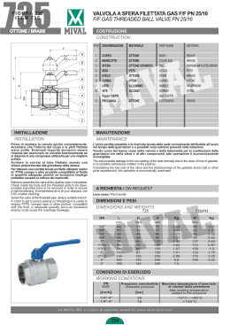
128L
TEC
4
6
5
7
3
8
2
1
9
2
Pos.
DESCRIZIONE / DESCRIPTION
8
2
8
Qt.
MATERIALE / MATERIAL
1
Corpo / Body
1
Ottone nichelato / Nickel-plated brass CW617N
2
Manicotto / End adapter
3
Ottone nichelato / Nickel-plated brass CW617N
3
Maniglia a leva / Lever handle
1
Alluminio / Aluminium
4
Vite / Screw
1
-
5
Asta di manovra / Stem
1
Ottone / Brass CW614N
6
Premistoppa / Packing gland
1
Ottone / Brass CW614N
7
Guarnizione / O-Ring
2
NBR
8
Sede / Seat
4
P.T.F.E.
9
Sfera / Ball
1
Ottone cromato / Chrome-plated brass CW617N
128T
TEC
4
6
5
7
3
8
2
1
9
2
Pos.
DESCRIZIONE / DESCRIPTION
8
2
8
Qt.
MATERIALE / MATERIAL
1
Corpo / Body
1
Ottone nichelato / Nickel-plated brass CW617N
2
Manicotto / End adapter
3
Ottone nichelato / Nickel-plated brass CW617N
3
Maniglia a leva / Lever handle
1
Alluminio / Aluminium
4
Vite / Screw
1
-
5
Asta di manovra / Stem
1
Ottone / Brass CW614N
6
Premistoppa / Packing gland
1
Ottone / Brass CW614N
7
Guarnizione / O-Ring
2
NBR
8
Sede / Seat
4
P.T.F.E.
9
Sfera / Ball
1
Ottone cromato / Chrome-plated brass CW617N
3-WAY BALL VALVE
T valve operation: with the handle disassembled is visible, on the stem, a T mark, which indicates the
running direction of the ball‘s holes, allowing the following combinations:
The flow go in all directions (A-B-C)
The flow go only from B to C (or vice versa)
The flow go only from A to C (or vice versa)
The flow go only from A to B (or vice versa)
L valve operation: with the handle disassembled is visible, on the stem, a L mark, which indicates the
running direction of the ball‘s holes, allowing the following combinations:
The flow go from B to C (or vice versa)
The flow is stopped
The flow is stopped
The flow go from A to B (or vice versa)
3-WAY BALL VALVE
INSTALLATION
TEC
TEC
LOSS
DIAGRAM
WITH WATER
2”
1/2
1”
1/4
1”
1”
”
3/4
1/2
3/8
1/4
1
m3/h
0,1
0,2
0,4
0,6
0,8
2
4
6
8
20
40
MISURE
1/4”
3/8”
1/2”
3/4”
1”
1”1/4
1”1/2
2”
Kv
1,5
2,5
3,5
7
12
19,5
37
52
60
80
Art. 128
0,1
”
”
bar
”
Art: 128
Scaricare