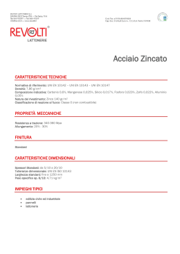
MATERIALI E DESIGNAZIONI.
MATERIALS AND DESIGNATIONS.
ALLUMINIO
ALUMINUM
CARATTERISTICHE MATERIALE
Tutti i profili presenti in questo catalogo, salvo diversa indicazione, sono estrusi in lega di alluminio UNI 9006/1
Designazione numerica 6060 al Mg Si 0.5 (a richiesta su alcuni profili lega 6063)
Stato fisico T5
Peso specifico Kg/dm3 2.7
MATERIAL CHARACTERISTICS
Unless otherwise specified, all profiles in this catalogue are
extruded in aluminum alloy UNI 9006/1.
Numerical designation 6060 at Mg Si 0.5 (upon request on
some alloy 6063 profiles)
Physical state T5
Specific weight Kg/dm3 2.7
TOLLERANZE DI ESTRUSIONE
Tutti I profili sono estrusi nel rispetto delle norme UNI 3879.
Per esigenze specifiche e per dissipatori realizzati su disegno
si possono ottenere tolleranze di estrusione fino al 50% delle norme UNI 3879.
Qualora vi siano delle dimensioni critiche, che devono essere
rispettate, queste devono essere concordate preventivamente.
EXTRUSION TOLERANCE
All profiles are extruded in compliance with UNI 3879 regulations. For specific needs and for heat sinks made to order it
is possible to obtain extrusion tolerances up to 50% of the
UNI 3879 regulation.
Whenever there are critical dimensions that must be respected, they must be agreed in advance.
TRATTAMENTI E FINITURE SUPERFICIALI
SURFACE TREATMENTS AND FINISHES
TRATTAMENTI SUPERFICIALI
Anodizzazione (nera, naturale, oro e colorata)
Decapaggio (sgrassaggio - sbiancatura)
Cromatazione (alodyne 1000 bianco
e alodyne 1200 giallo)
Nichelatura
Cromatura
Argentatura
Verniciatura
Serigrafia, ecc
SURFACE TREATMENTS
Anodization (black, natural, gold and colored)
Pickling (degreasing – bleaching)
Chromatizing (Alodyne 1000 white
Alodyne 1200 yellow)
Nickel-plating
Chromium plating
Silver-plating
Painting
Silk-screening, etc.
FINITURE SUPERFICIALI
Burattatura
Sabbiatura - pallinatura
Satinatura
Spazzolatura meccanica, ecc.
SURFACE FINISHES
Barrel finishing
Abrasive blasting – shot peening
Silking
Mechanical brushing, etc.
Specificare chiaramente se sono richieste esigenze estetiche.
Clearly specify if there are esthetic requirements.
RAME
COPPER
CARATTERISTICHE MATERIALE
Composizione materiale: secondo UNI 5649-71
Rame elettrolitico CU-ETP 99.9 %
MATERIAL CHARACTERISTICS
Material composition: according to UNI 5649-71
Electrolytic copper CU-ETP 99.9 %
TRATTAMENTI E FINITURE SUPERFICIALI
SURFACE TREATMENTS AND FINISHES
TRATTAMENTI SUPERFICIALI
Stagnatura
Argentatura
Nichelatura
Zincatura (nera)
FINITURE SUPERFICIALI
Satinatura
Spazzolatura meccanica
SURFACE TREATMENTS
Tinning
Silver-plating
Nickel-plating
Galvanizing (black)
SURFACE FINISHES
Silking
Mechanical brushing
5
TOLLERANZE DI LAVORAZIONE.
MACHINING TOLERANCE.
Tecnoal ha adottato come tolleranze usuali per le lavorazioni meccaniche ove non diversamente specificato
- taglio + 0 - 0,5
- riferimenti ± 0,3
- interassi ± 0,2 (non cumulabile)
- profondità filettature 2 volte il diametro più un millimetro.
Altre lavorazioni ove non specificato grado di precisione medio
secondo UNI 22768-1-m
Classe di tolleranza/Tolerance class
Designazione
Designation
Classe di
tolleranza
applicata
Applied
tolerance
class
f
m
c
v
Denominazione
Denomination
Fine/Thin
Media/Medium
Grossolana/Thick
Molto grossolana/Very thick
Unless otherwise indicated, Tecnoal has machining tolerances
as follows:
- cut + 0 - 0,5
- reference ± 0,3
- distances between centers ± 0,2 (non combinable)
- thread depths 2 times the diameter plus one millimeter.
Other machining where average degree of precision not specified according to UNI 22768–1-m
(*)
da/from
0.5
fino a/to
3
oltre/over
3
fino a/to
6
oltre/over
6
fino a/to
30
oltre/over
30
fino a/to
120
oltre/over
120
fino a/to
400
oltre/over
400
fino a/to
1000
oltre/over
1000
fino a/to
2000
oltre/over
2000
fino a/to
4000
± 0.05
± 0.1
± 0.2
––
± 0.05
± 0.1
± 0.3
± 0.5
± 0.1
± 0.2
± 0.5
±1
± 0.15
± 0.3
± 0.8
± 1.5
± 0.2
± 0.5
± 1.2
± 2.5
± 0.3
± 0.8
±2
±4
± 0.5
± 1.2
±3
±6
––
±2
±4
±8
(*) Per dimensioni nominali minori di 0,5 mm., gli scostamenti devono essere indicati vicino alla dimensione nominali relativa
(*) For nominal dimensions less than 0.5 mm, the deviation must be indicated near the relative nominal dimension.
CRITERI DI ACCETTAZIONE (UNI EN 22768-1)
Salvo indicazione contraria, i pezzi non conformi alle tolleranze generali prescritte non devono essere automaticamente rifiutati quando la funzionalità del pezzo non risulta compromessa.
ACCEPTANCE CRITERIA (UNI EN 22768-1)
Unless otherwise indicated, pieces not in compliance with the
general prescribed tolerances should not automatically be
refused when the functionality of the piece has not been compromised.
NOTE TECNICHE.
TECHNICAL NOTES.
Il presente catalogo è stato elaborato dal settore tecnicocommerciale della TECNOAL allo scopo di fornire al progettista elettronico un valido aiuto nella scelta del dissipatore
più adatto ad uno specifico impiego. I dati di resistenza termica (RT) riferiti ad un provino di data lunghezza L riportati
nella tabella di ogni profilo sono dati sperimentali riferiti a
risultati di prove di laboratorio.
Le condizioni di prova sono quelle che garantiscono il massimo rendimento del dissipatore, ovvero:
1) ventilazione naturale;
2) carico termico applicato su tutta la superficie caricabile;
3) posizione “verticale” per sfruttare il massimo “dell’effetto
camino” sul flusso dell’aria;
4) superficie opaca ossidata nera per favorire lo scambio termico anche per irraggiamento;
5) nessun corpo nelle vicinanze del dissipatore in prova per
minimizzare le perturbazioni ambientali;
6) temperatura rilevata tramite termocoppia all’interno del
dissipatore immediatamente sotto il carico in zona centrale del provino.
I valori riportati sul catalogo fanno riferimento ad un RT rilevata con una differenza di temperatura dissipatore-ambiente
∆T = 60 °C.
Questo è in effetti il carico massimo di utilizzo per la maggioranza dei dispositivi a stato solido. La logica conseguenza
di quanto sopra esposto è che per il progettista i valori della
RT riportati in catalogo sono solo una buona base di partenza per scegliere il dissipatore più adatto al proprio impiego
per arrivare al risultato definitivo occorre tenere conto che
6
This catalogue has been prepared by TECNOAL’s design marketing department in order to provide electronic design engineers with the means to choose the most suitable heat sink
for a given use.
The data regarding thermal resistance (TR) relative to a test
piece of a given length L indicated in the table of each profile are experimental data gleaned from the results of laboratory experiments.
The test conditions are those which guarantee maximum performance by the heat sink, and include:
1) natural ventilation
2) thermal load applied to the entire load surface
3) vertical position to take maximum advantage of the chimney effect on airflow
4) anodized black opaque surface to enhance thermal exchange
through heat radiation as well
5) absence of objects near the tested heat sink to minimize
environmental disturbances
6) temperature measured by means of a thermocouple inside
the heat sink immediately below the load in the center area
of the test piece.
The values indicated in the catalogue refer to a TR detected
with a heat sink-ambient temperature difference of ∆T = 60°C.
This is effectively the maximum load for usage of the majority of solid layer devices. The logical consequence of the above
is that the designer should use the TR values reported in the
catalogue only as a starting point in selecting the most suitable heat sink for a given use. In order to reach a definitive
result it is necessary to be aware that in reality the heat sink
nella realtà il dissipatore andrà ad operare in condizioni sicuramente peggiori di quelle presenti al momento della prova di
laboratorio. Un esempio molto semplice per chiarire il concetto se la potenza totale da dissipare è di 35W e imponiamo che il dispositivo possa arrivare alla temperatura massima
di 80°C con una temperatura ambiente di 30°C utilizzeremo
la semplice formula:
RT =
will be subject to worse conditions than those used in laboratory testing. A very simple example to clarify the concept:
if the total power to dissipate is 35W and we determine that
the device can reach a maximum temperature of 80°C with
an ambient temperature of 30°C, we can use the following
formula:
∆T
TR =
W
∆T
W
Dove:
Where:
RT = resistenza termica del dissipatore
∆T = temperatura massima del dissipatore meno
temperatura ambiente
W = potenza massima dissipata
TR = thermal resistance of the heat sink
∆T = maximum temperature of the heat sink minus
ambient temperature
W = maximum dissipated power
Sostituendo i valori del progetto nella formula abbiamo:
Substituting the project values in the formula we have:
∆T = 80 – 30 = 50 °C
W = 35 W
∆T = 80 - 30 = 50 °C
W = 35 W
Questo dato, ancora teorico, andrà diminuito leggermente per
renderlo realmente applicabile al progetto. Si può partire da
1,1 ÷ 1,3 °C/W.
A questo punto i dati riportati sul catalogo ci consentono
ampi margini di scelta trattandosi di individuare fra tanti profili di media potenza il più adatto per dimensioni e facilità di
montaggio al nostro utilizzo.
Difficilmente si troverà il valore della RT cercata direttamente
sulle tabelle, essendo i valori riportati relativi a lunghezze predeterminate; come è intuitivo occorrerà allungare o accorciare
il profilo per diminuire o aumentare la RT.
This theoretical result will be slightly reduced to make it more
realistically applicable to the project. A starting point would
be from 1.1 — 1.3 °C/W.
At this point the data indicated in the catalogue allow us a
wide range of choice in identifying among many profiles of
medium power the most suitable in terms of dimensions and
ease of installation for our use.
It is unlikely to find the desired TR value directly in the tables
as these indicated values regard predetermined lengths. As is
evident, it is necessary to lengthen or shorten the profile to
decrease or increase the TR.
ATTENZIONE!
Trattandosi di conduzione termica il valore della RT non cambia con legge lineare, ovvero: raddoppiando la lunghezza di
un dissipatore non si dimezza la sua resistenza termica! Va
inoltre tenuto conto che la disposizione del carico termico
influenza in modo determinante l’efficienza del dissipatore.
CAUTION!
Since thermal conduction is involved the TR value does not
change on a linear basis. For example, doubling the length of
the heat sink will not reduce its thermal resistance by one
half! It is also important to bear in mind that the thermal load
disposition has a determining effect on the effectiveness of the
heat sink.
VENTILAZIONE FORZATA
Nel caso che il dispositivo da progettare preveda la ventilazione
forzata, è ancora possibile utilizzare i dati del catalogo tenendo presente che la RT rilevata in ventilazione naturale diminuisce proporzionalmente all’aumento della velocità dell’aria.
In tabella 1 è riportato l’andamento puramente teorico di tale
diminuzione.
È pure possibile valutare in modo molto approssimato come
diminuisce la RT all’aumentare della lunghezza del dissipatore. Riportiamo in tabella 2 un tipico andamento.
Rt
1
FORCED VENTILATION
When the design involves the use of forced ventilation it is
still possible to use the catalogue data, bearing in mind that
the TR measured in natural ventilation decreases proportionally with the air velocity. Table 1 shows the purely theoretical trend of this decrease.
It is possible to approximately evaluate the decrease in TR
with the increase in heat sink length. Table 2 shows a typical
trend.
Fc
Convezione forzata/Forced ventilation
5
0.8
4
0.6
3
0.4
2
0.2
1
0
Fattore di correzione Rt/L/Correction coefficient Rt/L
0
2
4
6
0
0
50
100
150
200
250
m/sec
Lunghezza del dissipatore/Sink lenght
tabella 1 / table 1
tabella 2 / table 2
300
7
ATTENZIONE!
Tutti i fattori di non linearità che caratterizzano la conduzione termica sono enormemente amplificati in caso di ventilazione forzata. Bisogna infatti mettere in conto che la geometria del profilo, il tipo di ventilatore, la presenza o meno di un
convogliatore, l’insorgenza o meno di vortici, la disposizione
dei carichi termici, ecc. interagiscono contemporaneamente in
modo talmente imprevedibile da rendere praticamente improgettabile un dispositivo.
In questi casi solo la conoscenza, l’esperienza e le prove di
laboratorio possono aiutare il progettista.
E’ in effetti in questo contesto che la TECNOAL mette a completa disposizione il proprio laboratorio per risolvere rapidamente e nel modo migliore i problemi dei clienti.
IMPORTANTE
I dati e le informazioni riportate sul presente catalogo sono
stati rilevati in modo accurato e pertanto affidabili. Al cliente rimane comunque la responsabilità di verificare la correttezza dell’uso finale dei dispositivi.
La TECNOAL non potendo essere a conoscenza dell’uso specifico che ne sarà fatto non può essere ritenuta responsabile
in alcun modo per eventuali incidenti o danni provocati durante l’impiego dei suoi prodotti.
Si riserva altresì il diritto di apportare senza preavviso qualsiasi variazione ai propri prodotti, allo scopo di migliorarne la
qualità e l’efficienza.
Tutti i profili estrusi in alluminio sono soggetti alle norme di
tolleranza sull’estrusione UNI 3879; di conseguenza i pesi
riportati sono valori medi teorici e oscillano all’interno dei campi di tolleranze dimensionali.
8
CAUTION!
All non-linear factors that characterize thermal conduction
are greatly amplified with forced ventilation. It is necessary
to consider that geometric properties of the profile, the type
of fan, the presence (or lack) of a conveyor, the possibility of
vortexes, the disposition of thermal loads, etc. simultaneously interact in such an unpredictable way that make device
design nearly impossible. In these cases only knowledge, experience and laboratory testing can help the designer. It is exactly in these situations that TECNOAL makes it laboratory available to quickly resolve client problems with the best solutions.
IMPORTANT
The data and information contained in this catalogue have
been carefully compiled and are therefore reliable. However,
the client still has the responsibility of ensuring the correct
use of the devices. TECNOAL cannot know the specific use of
its products and therefore cannot be held responsible in any
way for any incidents or damage caused during the use of
such products. The company also reserves the right to modify its products without prior notice in order to improve their
quality and efficiency. All extruded aluminum profiles are subject to UNI 3879 regulations regarding extrusion tolerance.
Consequently, the indicated weights are theoretical average
values and vary within the range of dimension tolerances.
LEGA 6060.
LEGA ALLUMINIO - MAGNESIO - SILICIO PRIMARIA DA LAVORAZIONE PLASTICA
Designazione convenzionale della lega: EN AW - 6060 UNI 573-3
Designazione numerica: 6060
Applicazioni tipiche: estrusi a disegno e sistemi
Composizione chimica in peso %
Lega
Cu
FE
Mn
Mg
Zn
Si
Impurità
Al
6060
0,10
0,10-0,30
0,10
0,35-0,60
0,10
0,30-0,60
0,05-0,15
Resto
Estrusi proprietà fisiche tipiche
Lega
6060
Stato fisico
Densità
Resistività
elettrica
Conducibilità
termica
Intervallo
di fusione
Coefficiente
dilatazione
termica
Modolo
elasticità
Kg/dm3
Ohm mm2/mm
W/mk
°C
20-100 °Cx10-8/°C
N/mm2
270
0.034
0.031
0.033
193
209
201
615-655
23
69000
T1
T5
T6
Estrusi proprietà meccaniche tipiche
Lega
6060
Stato fisico
*
0
F
T1
T5
T6
Carico unitario
di rottura
a trazione
Carico unitario
di scostamento
della proporzionalità
Allungamento
Durezza
Brinell
Rm
N/mm2
RmpO.2
N/mm2
A
%
HB
22
18
16
15
40
45
60
70
≤ 140
≤ 80
100
120
185
205
70
145
165
Caratteristiche tecnologiche (indicative)
Stato fisico
Deformabilità
plastica a freddo
Lavorabilità
all’utensile
Resistenza
alla corrosione
atmosferica
Resistenza
alla corrosione
marina
Anodizzazione
Saldabilità
T1
T5
T6
Buona
Buona
Sufficiente
Sconsigliabile
Buona
Buona
Ottima
Ottima
Ottima
Buona
Buona
Buona
Ottima
Ottima
Ottima
Ottima
Ottima
Ottima
* Stato fisico
0
F
T1
T5
T6
42
Grezzo di estrusione
Ricotto
Raffreddato al termine di un processo di lavorazione plastica ad elevata temperatura ed invecchiamento naturale
Raffreddato al termine di un processo di lavorazione plastica ad elevata temperatura ed invecchiamento artificiale
Solubilizzato, temperato e invecchiato artificialmente
ALLOY 6060.
PRIMARY ALUMINUM - MAGNESIUM - SILICON ALLOY FOR ALLOY FORGING
Conventional alloy designation: EN AW - 6060 UNI 573-3
Numerical designation: 6060
Typical applications: design and systems extrusions
Chemical composition in weight %
Alloy
Cu
FE
Mn
Mg
Zn
Si
Impurity
Al
6060
0,10
0,10-0,30
0,10
0,35-0,60
0,10
0,30-0,60
0,05-0,15
Remaining
Typical physical properties of extrusions
Alloy
Physical state
6060
Density
Electrical
resistance
Thermal
conductivity
Melting
range
Thermal
expansion
coefficient
Elasticity
coefficient
Kg/dm3
Ohm mm2/mm
W/mk
°C
20-100 °Cx10-8/°C
N/mm2
270
0.034
0.031
0.033
193
209
201
615-655
23
69000
T1
T5
T6
Mechanical properties of typical extrusions
Lega
6060
Physical state
*
0
F
T1
T5
T6
Tensile
strength
at break
Unit load of
deviation from
proportionality
Elongation
Brinnel
hardness
Rm
N/mm2
RmpO.2
N/mm2
A
%
HB
22
18
16
15
40
45
60
70
≤ 140
≤ 80
100
120
185
205
70
145
165
Technological characteristics (indicative)
Physical state
Plastic
deformability cold
Tool
machinability
Resistance
to atmospheric
corrosion
Resistance
to marine
corrosion
Anodization
Weldability
T1
T5
T6
Good
Good
Sufficient
Not advisable
Good
Good
Excellent
Excellent
Excellent
Good
Good
Good
Excellent
Excellent
Excellent
Excellent
Excellent
Excellent
* Physical state
0
F
T1
T5
T6
extrusion blank
annealed
cooled subsequent to high temperature plastic forging and natural ageing
cooled subsequent to high temperature plastic forging and artificial ageing
solubilized, tempered and artificially aged
43
LEGA 6063
LEGA ALLUMINIO - MAGNESIO - SILICIO PRIMARIA DA LAVORAZIONE PLASTICA
Designazione convenzionale della lega: EN AW - 6063 UNI 573-3
Designazione numerica: 6063
Applicazioni tipiche: estrusi a disegno e sistemi
Lega adatta per quando servono caratteristiche meccaniche leggermente superiori alla lega 6060
Composizione chimica in peso %
Lega
Cu
FE
Mn
Mg
Zn
Si
Impurità
Al
6063
0,10
0.35
0,10
0,45-0,90
0,10
0,40-0,60
0,05-0,15
Resto
Estrusi proprietà fisiche tipiche
Lega
6063
Stato fisico
Densità
Resistività
elettrica
Conducibilità
termica
Intervallo
di fusione
Coefficiente
dilatazione
termica
Modolo
elasticità
Kg/dm3
Ohm mm2/mm
W/mk
°C
20-100 °Cx10-8/°C
N/mm2
2.70
0.033
201
615-655
23
69000
T6
Estrusi proprietà meccaniche tipiche (valore indicativo)
Lega
6063
Stato fisico
*
Carico unitario
di rottura
a trazione
Carico unitario
di scostamento
della proporzionalità
Allungamento
Durezza
Brinell
Rm
N/mm2
RmpO.2
N/mm2
A
%
HB
245
195
9
80
T6
Caratteristiche tecnologiche (indicative)
Stato fisico
Deformabilità
plastica a freddo
Lavorabilità
all’utensile
Resistenza
alla corrosione
atmosferica
Resistenza
alla corrosione
marina
Anodizzazione
Saldabilità
T6
Sufficiente
Buona
Ottima
Buona
Ottima
Ottima
* Stato fisico
T6 Tempra in acqua seguita da invecchiamento artificiale
44
ALLOY 6063.
PRIMARY ALUMINUM - MAGNESIUM - SILICON ALLOY FOR ALLOY FORGING
Conventional alloy designation: EN AW - 6063 UNI 573-3
Numerical designation: 6063
Typical applications: design and systems extrusions
Alloy suitable when mechanical characteristics slightly superior to Alloy 6060 are needed
Chemical composition in weight %
Alloy
Cu
FE
Mn
Mg
Zn
Si
Impurity
Al
6063
0,10
0.35
0,10
0,45-0,90
0,10
0,40-0,60
0,05-0,15
Remaining
Typical physical properties of extrusions
Alloy
Physical state
6063
T6
Density
Electrical
resistance
Thermal
conductivity
Melting
range
Thermal
expansion
coefficient
Elasticity
coefficient
Kg/dm3
Ohm mm2/mm
W/mk
°C
20-100 °Cx10-8/°C
N/mm2
2.70
0.033
201
615-655
23
69000
Mechanical properties of typical extrusions (indicative values)
Alloy
6063
Physical state
*
Tensile
strength
at break
Unit load of
deviation from
proportionality
Elongation
Brinnel
hardness
Rm
N/mm2
RmpO.2
N/mm2
A
%
HB
245
195
9
80
T6
Technological characteristics (indicative)
Physical state
Plastic
deformability cold
Tool
machinability
Resistance
to atmospheric
corrosion
Resistance
to marine
corrosion
Anodization
Weldability
T6
Sufficient
Good
Excellent
Good
Excellent
Excellent
* Physical state
T6 tempered in water followed by artificial ageing
45
TOLLERANZE DI ESTRUSIONE.
ESTRATTO DA UNI 3879 RELATIVO ALL’ESTRUSIONE DEI PROFILI IN LEGA DI ALUMINIO
- TOLLERANZE DIMENSIONALI
Tolleranze ammesse sulle dimensioni della sezione trasversale dei profilati estrusi sono indicate nella
seguente tabella
Esempio:
DIMENSIONE
Dimensione
Dimensione
Dimensione
≤2
>2a≤3
>3a≤5
> 5 a ≤ 10
> 10 a ≤ 15
> 15 a ≤ 30
> 30 a ≤ 50
TOLLERANZE
± 0.15
± 0.20
± 0.25
± 0.30
± 0.35
± 0.40
± 0.50
DIMENSIONE
TOLLERANZE
> 50 a ≤ 80
> 80 a ≤ 100
> 100 a ≤ 120
> 120 a ≤ 150
> 150 a ≤ 200
> 200 a ≤ 250
> 250 a ≤ 300
± 0.80
± 1.00
± 1.20
± 1.30
± 1.50
± 1.80
± 2.10
Tolleranze per dimensioni > 300 mm devono essere concordate
- PLANARITÀ
Planarità
Nei fianchi piani dei profilati estrusi è tollerata una deformazione avente freccia di curvatura f ± 0.5%
della larghezza L del fianco stesso. Qualunque sia la larghezza del fianco.
È ammesso un valore minimo per detta tolleranza di ± 0.15 mm
- APERTURA ANGOLARE
Sull’apertura angolare tra due fianchi sono ammesse le tolleranze indicate nella seguente tabella
SPESSORE DELL’ALETTA
PIÙ SOTTILE TRA LE DUE
CHE COMPONGONO L’ANGOLO
S mm
≤5
> 5 a ≤ 20
> 20
TOLLERANZA
∆α
± 2°
± 1°30’
± 1°
Per esigenze particolari le tolleranze possono essere ridotte rispettivamente a:
± 1°30’ ; ± 1° ; ± 30’
46
EXTRUSION TOLERANCE.
EXTRACT FROM UNI 3879 REGARDING THE EXTRUSION OF ALUMINUM ALLOY PROFILES
- DIMENSIONAL TOLERANCE
Allowed tolerances on the dimensions of the cross-section of extruded profiles are indicated in the following table
Example:
Dimension
Dimension
Dimension
DIMENSIONS
TOLERANCE
DIMENSIONS
TOLERANCE
≤2
>2a≤3
>3a≤5
> 5 a ≤ 10
> 10 a ≤ 15
> 15 a ≤ 30
> 30 a ≤ 50
- 0.15
- 0.20
- 0.25
- 0.30
- 0.35
- 0.40
- 0.50
> 50 a ≤ 80
> 80 a ≤ 100
> 100 a ≤ 120
> 120 a ≤ 150
> 150 a ≤ 200
> 200 a ≤ 250
> 250 a ≤ 300
± 0.80
± 1.00
± 1.20
± 1.30
± 1.50
± 1.80
± 2.10
Tolerance by dimension >300 mm must be agreed
- FLATNESS
A deformation having a bending rise of f ± 0.5% of the length L of the side is tolerated on the flat
sides of extruded profiles. No matter the length of the side.
A minimum value for said tolerance of ± 0.15 mm is allowed.
- ANGULAR APERTURE
The tolerances indicated in the following table are allowed in the angular aperture between two sides.
GAUGE OF THE THINNER FIN
OF THE TWO THAT COMPRISE
THE ANGLE
S mm
≤5
> 5 to ≤ 20
> 20
TOLERANCE
∆α
± 2°
± 1°30’
± 1°
For particular needs the tolerances can be reduced, respectively, to:
± 1°30’ ; ± 1° ; ± 30’
47
Scaricare