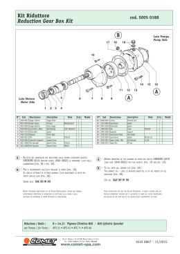
2445.05 Riduttore per pompe serie LT – XLT
1
2
3
4
5
6
7
8
9
10
11
12
13
14
15
16
17
18
19
20
21
22
23
24
25
26
27
0202.91
1600.11
1600.10
1802.20
1401.03
1400.51
1802.21
1400.53
1400.52
0301.20
1207.58
0001.91
1500.21
1500.22
0213.51
0603.02
1601.17
1801.21
1401.03
0700.05
0500.92
0500.94
0601.92
0601.93
1408.11
1801.21
0601.94
1803.05
1207.55
1207.57
Descrizione
Carter
Tappo
Tappo carico olio
Vite 5/16" x1”
Rosetta elastica Ø8,4
Rosetta piana Ø8.4
Vite 3/8”
Rosetta elastica Ø10
Rosetta piana Ø10
Distanziale
Pignone Z17
Anello radiale
Anello elastico
Anello elastico
Cuscinetto a sfere
Guarnizione 3/8
Tappo G3/8
Vite M8x25
Rosetta elastica Ø8,4
Spia livello olio
Flangia
Flangia
Anello OR
Anello OR
Rosetta tenuta Ø8
Vite M8x25
Anello OR
Vite M8x10
Corona Z37 Ø24
Corona Z37 Ø25
Description
Gear housing
Plug
Oil plug
Hexagonal screw
Lock-Washer
Washer
Screw
Lock-Washer
Washer
Spacer
Pinion
Housing seal
Snap ring
Snap ring
Ball Bearing
Gasket
Plug
Screw
Lock-Washer
Oil sight glass
Flange
Flange
O-Ring
O-Ring
Seal washer
Screw
O-Ring
Set screw
Gear Dia.24
Gear Dia.25
Q.tà
Q.ty
1
1
1
4
4
4
4
4
4
4
1
1
1
1
2
1
1
4
4
1
1
1
1
1
1
4
1
1
1
1
2445.09
Codice
Part
Pos.
Item Number
2445.05
Gearbox for pumps LT - XLT series
2445.09 Riduttore per pompe serie NMT-NPM-LTI-XLTI-PXI
Gearbox for pumps NMT-NPM-LTI-XLTI-PXI series
ISTRUZIONI PER IL MONTAGGIO
ASSEMBLY INSTRUCTIONS
RIDUTTORE SU POMPA
Con l’albero della pompa in posizione verticale,
smontare le quattro viti che fissano il coperchio
cuscinetto al carter pompa, lasciandolo nella sua
posizione.
Dopo aver inserito nella sua sede l’anello OR pos.
22, fissare la flangia pos. 21 utilizzando le viti pos.
24 con le relative rosette di tenuta, applicando sul
filetto Loctite 242 e serrando con coppia di 3Nm.
Controllare che la chiavetta sia correttamente in
sede, quindi montare la corona dentata pos. 27
sull’albero pompa spingendola in appoggio
sull’apposito spallamento e bloccandola in posizione
con la vite pos. 26 (applicare Loctite 242).
Completare il montaggio del carter (scatola
riduttore premontata con pignone, cuscinetto e
guarnizione olio) con la spia livello olio pos. 20 ed il
tappo discarico pos. 17 con relativa guarnizione.
Inserire l’anello OR pos. 25 sulla flangia
precedentemente fissata alla pompa, quindi
procedere al montaggio del carter riduttore sulla
pompa stessa utilizzando le viti pos. 18 e le relative
rosette elastiche, serrando con coppia di 8 Nm.
A questo punto è possibile procedere al
riempimento del carter riduttore con olio tipo
cambio differenziale SAE 90, fino al raggiungimento
della livello indicato dalla spia livello olio pos. 20,
chiudendo quindi con il tappo con sfiato pos. 3. Nel
caso che il gruppo pompa-riduttore non sia
immediatamente accoppiato al motore e debba
essere trasportato, per evitare possibili perdite di
olio utilizzare provvisoriamente il tappo pos. 2 in
dotazione a questo scopo.
GEAR BOX TO PUMP
Place the pump crankshaft in upright position,
remove the four bolts which fix the bearing
flange to the pump crankcase and leave the
bearing flange in its position.
Insert the O-ring pos. 22 into its groove, fix the
flange pos. 21 with the bolts pos. 24 and the seal
washers provided for the purpose applying
Loctite 242 on their threads and tighten with 3
Nm torque (26 in.lbs).
Make sure that the key is correctly housed in the
keyway, then assemble the crown gear pos. 27
into the pump crankshaft pushing it onto the
suitable shoulder and tighten with the screw pos.
26 (use Loctite 242).
Complete the assembly of the gear box crankcase
(pre-assembled gear box with pinion, bearings
and oil seal) with the oil sight glass pos. 20 and
the discharge plug pos. 17 and its gasket.
Insert the o-ring pos.25 on the flange already
fixed to the pump then assemble the complete
gear box crankcase on the flange using the bolts
pos. 18 and their elastic washers with a torque
setting of 8 Nm (70 in.lbs.).
Now fill the gear box with oil (differential gear
type, SAE 90) up to the oil sight glass level and
close with the vented plug pos. 3.
If the gear-box/pump unit is not immediately
coupled to the engine or should be transported,
in order to avoid any oil leakage we recommend
using the interim plug pos. 2 specially provided
for the purpose.
POMPA-RIDUTTORE SU MOTORE
Controllare che la chiavetta dell’albero del motore
sia correttamente in sede, quindi applicare
sull’albero stesso un buon lubrificante antigrippante
(es. Loctite 8150), per facilitare l’eventuale
smontaggio.
Procedere quindi all’accoppiamento del gruppo
pompa-riduttore al motore fissandolo con la
apposite viti e rosette in dotazione. Nel caso
vengano utilizzate le viti pos. 4 da 5/16”, serrare
con 8NM; per le viti pos. 7 da 3/8” serrare con 12
Nm.
GEAR-BOX/PUMP UNIT TO THE ENGINE
Make sure that the engine shaft key is correctly
housed in the keyway, then apply a good antiseize lubricant (e.g. Loctite 8150) on the engine
shaft to facilitate the possible disassembly.
Now you can couple the gear-box/pump unit to
the engine by using the specially provided bolts
and washers. When using 5/16” bolts pos.4, the
torque setting shall be 8 Nm (70 in.lbs.). If 3/8”
bolts pos. 7 are used, the torque setting shall be
12 Nm (110 in.lbs.)
Scaricare