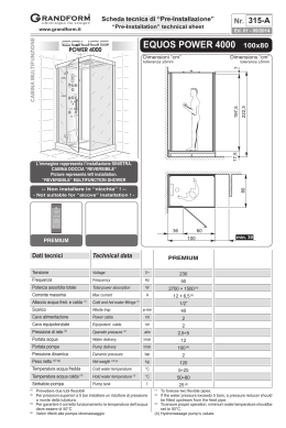
Scheda tecnica di “Pre-Installazione”
Nr. 121-A
“Pre-Installation” technical sheet
VASCA - BATHTUB
www.grandform.it
Ed. 01 - 02/2013
VISIO 145
145x145
Dimensioni “cm”
Dimensions “cm”
tolleranza ±5mm
tolerance ±5mm
Disegni e schemi rappresentano la versione SINISTRA.
La versione DESTRA è speculare.
Drawings and plats shows the LEFT side version.
The RIGHT side version is mirrow-like.
senza
sistema
Pool
Digital
Le quote si riferiscono alla sola vasca, pannelli esclusi
The dimensions refer only the bathtub, excluded panels
Digital
plus
Air
Easy
MULTISENS
senza
sistema
Pool
Digital
Digital
Plus
Air
Easy
MULTISENS
---
P
P
P+B
B
B
REMOTE CONTROL
senza
sistema
Dati
tecnici
Technical data
Pool
Digital
Digital
Plus
without
(w = acqua) (a = aria)
(w = water) (a = air)
system
(w)
(w)
(w + a)
REMOTE CONTROL
Air
Easy
(a)
MULTISENS
REMOTE
CONTROL
(a)
Tensione
Voltage
V~ -- 230230230230230
Frequenza
Frequency
Hz -- 5050505050
Potenza assorbita totale
Total power absorption
W --
Potenza assorbita pompa
Pump power absorption
W --550550550-- --
Potenza assorbita blower
Blower power absorption
W --
550 550 1000 450 450
-- -- 450450450
Potenza mantenim. tempertura Temp. maintenance absorb.
W ------------
Corrente massima
Max current
A
Allaccio acqua fred. e calda (1)
Cold and hot water fittings (1)
Scarico
Waste trap
Cavo alimentazione
Power cable
Cavo equipotenziale
Equipotent. cable
mt --22222
Pressione di rete (2)
Operatin pressure (2)
atm 2÷42÷42÷42÷42÷42÷4
Portata acqua
Water delivery
l/min 8÷138÷138÷138÷138÷138÷13
Peso netto (±5 kg)
Net weigth (±5 kg)
kg
657070 757070
Volume acqua
Water volume
(1)
(2)
--
2,5
2,5
8
2
2
1/2”1/2”1/2”1/2”1/2”1/2”
ø mm 404040404040
l
Prevedere due tubi flessibili
Per pressioni superiori a 5 bar installare un riduttore di pressione
a monte della tubatura.
390390390 390390390
(1)
(2)
To preview two flexible pipes.
If the water pressure exceeds 5 bars, a pressure reducer should
be fitted upstream from the feed pipe.
Schema di installazione
Installation plan
VISIO 145
145x145
Rubinetteria
a muro
Wall-mounted
tapware
Rubinetteria a muro
(senza erogazione)
Wall-mounted tapware
(without mains supply)
Il disegno rappresenta
una installazione SX.
La DX è speculare.
The drawing represent
LEFT installation. The Versione “Senza sistema”: NO predisposizioni “A” - “B” - “E”
RIGHT inst. is mirror-like “Without system” version: NO predispositions “A” - “B” - “E”
A - Allaccio elettrico per idromassaggio IPX5
(scatola con pressacavo PG13,5) Tensione
230V CA
CA (max)
(max)
230V
Uscita cavo
cavo alimentaz.
alimentaz. mt.2
mt.2 tipo
tipo H05-3x2,5
H05-3x2,5
Uscita
2
2
mm
2 o 3x4,0 mm2 (a seconda del sistema)
mm o 3x4,0 mm (a seconda del sistema)
B - Uscita cavo equipotenziale - lunghezza 2 mt
B - Uscita cavo equipotenziale - lunghezza 2 mt
C - Attacco acqua calda per rubinetteria 1/2”
C - Attacco acqua calda per rubinetteria 1/2”
F - Attacco acqua fredda per rubinetteria 1/2”
F
acqua
fredda perelettrica
rubinetteria 1/2”
E -- Attacco
Area cavi
alimentazione
E
cavia alimentazione
elettrica
V -
- Area
Scarico
pavimento ø 40mm
V
pavimento
ø 40mm
J - Scarico
Attacco aacqua
miscelata
da 1/2” per collegamento cascata di serie
L’installazione
L’installazione deve
deve avvenire
avvenire aa pavimento
pavimento ee
pareti
pareti finite.
finite.
A - Electrical connect. for IPX5 box (PG13,5 junction Le misure sono All measurement
in “cm”
are in “cm”
box with cable seal) 230 V AC (max.) voltage
m. power
power cable
cable output,
output, H05-3x2,5
H05-3x2,5 mm
mm22 oo
22 m.
35
D= 145 Q=
3x4,0 mm
mm22 type
type (based
(based on
on the
the system
system type). type).
3x4,0
B
-
Equipotential
bonding
conductor
output
lenght
R=
8
G=
145
B - Equipotential bonding conductor output - lenght
2mt
15
L= 120 S=
2mt
C - Hot water fitting for 1/2” tapware
M=
15 T=35
C - Hot water fitting for 1/2” tapware
F - Cold water fitting for 1/2” tapware
U=50
N=35
F
-
Cold
water
fitting
for
1/2”
tapware
E - Line cord area
E
corddrain
area fitting
P=62,5 Y=16
V -
- Line
ø 40mm
V
40mm
drain
fitting
J - ø
1/2”
fitting
mixer
water for standard cascade
connection
Installation
Installation should
should occur
occur once
once both
both the
the floor
floor
and
and walls
walls are
are completed.
completed.
Accertarsi che l’impianto elettrico dello stabile sia conforme alle norme CEI 64.8 e
protetto da un interruttore differenziale accertandosi che l’impianto di messa a terra
sia efficiente e conforme alle disposizioni CEI. Il collegamento elettrico dell’impianto
idromassaggio, va eseguito in modo fisso e permanente e deve essere controllato
da un interruttore omnipolare con apertura dei contatti di almeno 3 mm, ed avere un
potere di interruzione pari a 16A o 25A (a seconda del tipo di sistema), posto fuori
dalle zone 0,1,2,3 e comunque lontano da possibili erogazioni o spruzzi d’acqua.
Il cavo di alimentazione alla centralina, deve essere del tipo H05 a tre conduttori
di sezione non inferiore a 2,5 mm2 o 4,0 mm2 (a seconda del tipo di sistema). Per il
passaggio nelle pareti di detto cavo, usare l’apposito tubo corrugato di tipo PT.
La responsabilità del Costruttore decade nel caso in cui i componenti elettrici
dell’apparecchio, vengano manomessi o sostituiti con ricambi non originali e/o non
riconosciuti conformi dal Costruttore.
Make sure the building electrical installation conforms to the EIC 64.8 standard and
that it is protected by a magnetic circuit breaker, ascertaining also that the grounding
terminal is efficient and fully compliant with IEC provisions. The electrical connection
of the bathtub shall be carried out permanently and be monitored by a single-pole
switch, whose contacts can open 3mm at least and featuring a cut-out capacity
equal to 16A or 25A (based on the system type), located outside areas 0, 1, 2 and
3 and at any rate, as far as possible from water supply or jets.
The power-cord to the controller must be H05 with a three conductor cross-section
is not less than 2,5 mm2 or 4,0 mm2 (based on the system type). To drive the cord
through the walls, use the appropriately supplied PT corrugated pipe.
This warranty is void if failure has resulted from the electrical components of the
appliance being either tampered with or replaced by second-hand spare parts, and/
or spare parts whose conformity is not acknowledged by the manufacturer..
IL COSTRUTTORE NON E’ RESPONSABILE PER I DANNI DOVUTI AD UNA ERRATA O NON CONFORME INSTALLAZIONE.
IN NO EVENT SHALL THE MANUFACTURER BE LIABLE FOR ANY DAMAGES WHATSOEVER THAT MAY ARISE FROM INAPPROPRIATE AND NON-COMPLIANT INSTALLATION PROCEDURES.
I dati e le caratteristiche indicate non impegnano la SFA S.p.A., che si riserva il diritto di apportare tutte le modifiche ritenute opportune senza obbligo di preavviso o sostituzione
Neither the information nor the characteristics reported are binding for SFA S.p.A. which reserves the right to make any improvements, as deemed necessary, without notice or with no liability to replacement.
Rubinetteria a bordo vasca
Bath-side tapware
Scaricare