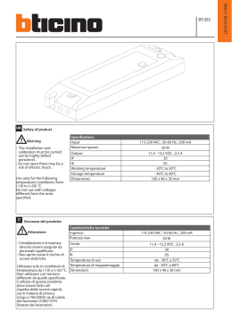
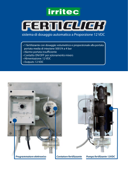
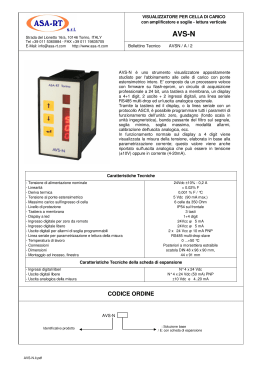
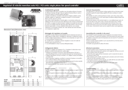
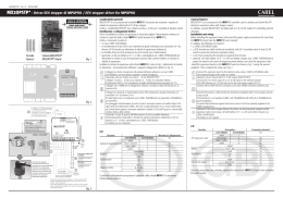
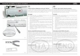
cod. +050003265 rel. 1.1 - 31.03.2004
pCOE
Scheda espansione I/O: PCOE****** / I/O Expansion board: PCOE******
LEGGI E CONSERVA
QUESTE ISTRUZIONI
READ AND SAVE
THESE INSTRUCTIONS
General characteristics
La scheda di espansione “PCOE000TLN0 e PCOE0004850” è un dispositivo elettronico che fa parte della famiglia pCO
sistema ed è stata progettata per facilitare l’incremento dell’ I/O dei controllori pCOXS, pCO1, pCO2. Si possono collegare al
massimo 5 schede di espansione per ogni controllore pCOXS, pCO1, pCO2.
The expansion board “PCOE000TLN0 and PCOE0004850” is an electronic device that belongs to the pCO sistema product
family and have been designed to increase the I/Os on the pCOXS, pCO1, pCO2 controllers. A maximum of 5 expansion
boards for each pCOXS, pCO1, pCO2 controller can be connected.
Versioni disponibili:
• PCOE00TLN0 versione tLAN (protocollo proprietario CAREL)
• PCOE004850 versione RS485 (protoccolo supervisore CAREL 3.0)
Available models:
• PCOE00TLN0 tLAN version (CAREL proprietary protocol)
• PCOE004850 RS485 version (CAREL 3.0 supervisor protocol)
Controllore
Controller
Espansione collegata
PCOE000TLN0 PCOE0004850
x
x
x
C4
NC4
NO4
C3
NC3
+Vdc
GND
+5V Ref
B3
J10
6
Key
1. power supply connector [G (+), G0 (-)];
2. analogue output 0 to 10 V ;
3. network connector for expansions in RS485 (GND, T+, T-) or tLAN (GND, T+);
4. 24Vac/Vdc digital inputs;
5. yellow LED showing power supply voltage and 3 signalling LEDs;
6. serial address;
7. analogue inputs and probe supply;
8. relay digital outputs.
Alimentazione
Power supply
Nell’installazione si deve utilizzare un trasformatore di sicurezza in Classe II di almeno 15 VA, per l’alimentazione di una sola
espansione. Si raccomanda di separare l’alimentazione dell’espansione pCOE da quella del resto dei dispositivi elettrici
(contattori ed altri componenti elettromeccanici) all’interno del quadro elettrico. Qualora il secondario del trasformatore sia
posto a terra, verificare che il conduttore di terra sia collegato al morsetto G0. Assicurarsi che siano rispettati i riferimenti G e
G0 di tutte le schede presenti nel quadro (il riferimento G0 deve essere mantenuto per tutte le schede).
When installing one expansion, a safety Class IItransformer rated at least 15VA must be used.
It is advisable to keep separate the pCOE controller from the power supply of the other electric devices (contactors and other
electromechanical components) in the electric panel. If the transformer secondary winding is grounded, check that the
ground cable is connected to G0 terminal. Make sure that the G and G0 references of all the boards mounted on the panel
have the same polarity. (G0 reference must be kept in every board).
Caratteristiche tecniche
Technical specifications
Caratteristiche meccaniche
Mechanical specifications
dimensioni
montaggio
dimensions
mounting
inseribile su 4 moduli DIN, 110x70x60 mm;
su guida DIN.
Plastic enclosure
•
•
•
•
•
•
•
•
•
•
•
•
•
•
agganciabile su guida DIN secondo norme DIN 43880 e CEI EN 50022;
materiale: tecnopolimero;
autoestinguenza: V0 (secondo UL94) e 960 °C (secondo IEC 695);
prova biglia: 125 °C;
resistenza alle correnti striscianti: ≥ 250 V;
colore: grigio RAL7035;
feritoie di raffreddamento.
conversione analogica
numero e tipo
T-
T+
GND
costante di tempo ingressi
resistenza interna ingressi 0...20 mA
5
3
Fig. 1
can be mounted on 4 DIN modules, 110x70x60 mm;
on DIN rail.
Contenitore plastico
it can be fastened on DIN rail according to DIN 43880 and CEI EN 50022 standards;
material: technopolymer;
self-extinguishing: V0 (complying with UL94) and 960 °C (complying with IEC 695);
ball pressure test:125 °C;
comparative tracking index: ≥ 250 V;
colour: RAL7035 grey;
cooling vent-holes.
Electrical specifications
28 Vdc +10/-20 % e 24 Vac +10/-15% 50...60 Hz - assorbimento massimo P= 6 W
con connettori maschio/femmina estraibili, tensione max. 250 Vac
sezione cavo: min. 0,5 mm2 - max 2,5 mm2
single chip 8 bit; 4,91 MHz
0,5 s
19200 bit/s
Ingressi analogici
J3
tLAN
Y1
VG0
ID4
IDC1
VG
G0
ID3
ID2
ID1
G
J2
2
NOTES
standard
with the optional PCO1000TLN0 board mounted on pCO1
standard on Large version
Legenda
1. connettore per l’alimentazione [G (+), G0 (-)];
2. uscita analogica 0...10 V;
3. connettore rete espansioni in RS485 (GND, T+, T-) o tLAN (GND, T+);
4. ingressi digitali a 24 Vac/Vdc;
5. LED giallo indicazione presenza tensione di alimentazione e 3 LED di segnalazione;
6 indirizzo seriale;
7. ingressi analogici e alimentazione sonde;
8. uscite digitali a relè.
CPU
tempi di ritardo azionamenti
max. velocità trasmissione
Serial
Address
1 2 3 4
J4
1
pCOXS
pCO1
pCO2
To increase the response speed to an alarm situation, the master can enable an inhibition matrix. In case the values
transmitted by the master are not consistent with the actions undertaken by the inhibition matrix an “I/O Mis-mach” error is
generated.
alimentazione
morsettiera
J1 24Vac
Connected expansion board
PCOE000TLN0 PCOE0004850
x
x
x
Per aumentare la velocità di risposta ad una situazione di allarme, il master può impostare l’attivazione di una matrice di
inibizione. Nel caso di incoerenza tra valori trasmessi dal master e azioni intraprese dalla matrice di inibizione viene creato
un errore di “I/O Mis-mach”.
Caratteristiche elettriche
expansion board
4
NOTE
Di serie
Con l’utilizzo della scheda opzione PCO1000TLN0 montata sul pCO1
Di serie ma solo versione Large
J8
B4
J7
+Vdc
GND
+5V Ref
J9
NO3
C2
NC2
NO2
C1
NC1
NO1
7
B2
J6
B1
J5
Thank you for your choice. We trust you will be satisfied with your purchase.
Caratteristiche generali
pCOXS
pCO1
pCO2
8
GB
Vi ringraziamo per la scelta fatta, sicuri che sarete soddisfatti del vostro acquisto.
power
terminal block
CPU
Operation delay time
Max. transmission speed
Analogue inputs
A/D converter a 10 bit CPU built-in
4 sensori di tipo NTC Carel (-50T90 °C; R/T 10 kΩ a 25 °C), tensione: 0/1 Vdc o 0/5 Vdc,
corrente: 0...20 mA o 4...20 mA, selezionabili via software due a due
(B1, B2 e B3, B4)
1s
100 Ω
AVVERTENZA: per l’alimentazione di eventuali sonde attive, è possibile utilizzare i 12 Vdc disponibili sul morsetto +Vdc, la
corrente massima erogabile è di 100 mA protetta contro i corti circuiti. Per alimentare le sonde 0...5V utilizzare +5 Vref (30
mA max). Come il pCO1 e pCO2 il segnale 0/1 Vdc è da intendersi limitato al range ristretto 0-1 V e non è quindi sempre
compatibile con il segnale standard 10 mV/°C delle sonde Carel (per temperature negative e superiori a 100 °C può
generare allarme sonda), per i segnali in temperatura usare quindi 4...20 mA o NTC.
analogue conversion
number and type
28 Vdc +10/-20 % and 24 Vac +10/-15% 50to 60 Hz - P= 6 W maximum absorption
with removable-screw male/female connectors - max. voltage: 250 Vac
cable cross-section: min. 0.5 mm2 – max. 2.5 mm2
single chip 8 bit; 4,91 MHz
0.5 s
19200 bit/s
GB
10 bit A/D converter, built-in CPU
4 Carel NTC sensors (-50T90 °C; R/T 10 kΩ at 25 °C), voltage: 0/1 Vdc or 0/5 Vdc,
current: 0 to 20 mA or 4 to 20 mA, can be selected via software two by two
(B1, B2 and B3, B4)
time constant for each input
1s
0 to 20 mA inputs internal resistance 100 Ω
WARNING: To power any active probe, it is possible to use the 12 Vdc placed on +Vdc terminal; the max. current that can
be delivered is 100mA thermally protected against short circuits. To power 0 to 5 V probes use + 5 Vref (30 mA max.). Like
the pCO1 and pCO2 the 0/1 Vdc signal is limited to the restricted range 0 to 1 V, so it is not always compatible with the
standard signal 10 mV/°C of Carel probes (if the temperature is below zero or higher than 100 °C, it can cause probe alarm).
So, for the temperature signals use 4 to 20mA or NTC.
Dimensioni Espansione / Expansion dimensions
111
numero e tipo
70
Digital inputs
Ingressi digitali
60
4 optoisolati a 24 Vac 50...60 Hz o 24 Vdc (comune negativo)
number and type
4 optoisolated D.I. 24 Vac 50 to 60 Hz or 24 Vdc (negative common)
AVVERTENZE:
1 in conformità alle normative sulla compatibilità elettromagnetica, si utilizzi cavo schermato per la linea RS485, nel caso di
installazione dell’apparecchiatura in ambiente domestico;
2 è necessario connettere un fusibile da 1,25 AT sulla linea di alimentazione del dispositivo;
3 utilizzzare cavi di lunghezza max. 30 m escluso il cavo di alimentazione, quello di trasmissione dati RS485 e quello di
connessione tLAN;
4 separare quanto più possibile i cavi dei segnali delle sonde e degli ingressi digitali dai cavi relativi ai carichi induttivi e di
potenza, per evitare possibili disturbi elettromagnetici.
5 Tra l’ingresso digitale e il resto della scheda l’isolamento è principale.
WARNING:
1 in compliance with the standards on the electromagnetic compatibility, use the shielded cable for the RS485 line, in case
of the installation of the equipment in domestic ambient;
2 it is necessary to connect a 1.25 aT fuse to the device power supply network;
3 use cables with 30 m max. length, except for power supply, RS485 data transmission and tLAN connection cables;
4 please keep probe and digital input leads as far as possible from power cables to avoid possible electromagnetic noise.
5 Between the digital input and the rest of the board there’s a main insulation.
Uscite analogiche
Analogue outputs
numero e tipo
1 uscita (Y1) 0/10Vdc optoisolata
alimentazione
esterna 24 Vac/Vdc (con 24 Vdc positivo su VG)
risoluzione
8 bit
precisione
1%
carico massimo
1 kΩ (10 mA)
l’isolamento tra uscita analogica con la sua alimentazione e il resto della scheda è principale.
number and type
1 output (Y1) optoinsulated 0/10Vdc
power supply
external 24 Vac/Vdc (with 24 Vdc positive on VG)
resolution
8 bit
precision
1%
max. load
1 kΩ (10 mA)
The analogue output (Y1) is isolated from the main board including its power supply (VG-VG0)
Fig. 1
Uscite digitali
Indirizzamento seriale / Serial address
Esempio indirizzo 1
Example address 1
Esempio indirizzo 5
Example address 5
Serial Address
ON
Caratteristiche dei relè
Relay characteristics
2000 VA, 250 Vac, 8 A AC1,
2 A FLA, 12 A LRA, D300 secondo UL, (30.000 cicli)
2 A resistivi, 2 A induttivi, cosϕ=0,4, 2(2) A secondo EN 60730-1, (100.000 cicli)
tipo
connettore
driver
ON
1 2 3 4
ON
1 2 3 4
Significato LED di segnalazione (vedi Fig. 1 punto 5) / Signal LED meaning (see Fig. 1 point 5)
LED rosso
acceso
lampeggiante
-
LED giallo
acceso
-
LED verde
acceso
-
significato
protocollo supervisore CAREL/tLAN attivo
errore sonde
errore di “I/O mis-match” causato dalla matrice di inibizione
mancanza comunicazione
attesa di inizializzazione del sistema da parte del master (max. 30 s)
red LED
ON
flashing
-
yellow LED
ON
-
green LED
ON
-
meaning
active CAREL/tLAN supervisor protocol
probe error
“I/O mis-match” error caused by the inhibition matrix
lack of communication
waiting for the system startup by the master (max. 30 s)
CAREL S.p.A.
Via dell’Industria, 11 - 35020 Brugine - Padova (Italy)
Tel. (+39) 0499716611 – Fax (+39) 0499716600
http: // www . carel . com – e-mail: carel @ carel . com
number and type
commutable power
approvals
relay 4; all changeover
2000 VA, 250 Vac, 8 A AC1,
2A FLA, 12A LRA, D300 according to UL, (30.000 cycles)
2 A resistive, 2 A inductive, cosϕ= 0.4, 2(2)A according to EN 60730-1, (100.000 cycles)
Connection to the pCO
Collegamento al pCO
T-
T+
J3
tLAN
GND
There’s a main insulation among the relays; the double-insulation does exist towards the rest of the control.
potenza commutabile
omologazioni
1 2 3 4
Digital outputs
numero e tipo
4 a relè; tutti in scambio
L’isolamento tra i relè è di tipo principale; tra ogni morsetto delle uscite digitali e il resto del controllo esiste il doppio
isolamento.
asincrono half duplex a 2 fili dedicato
connettore estraibile a vite 3 vie (versione 485), 2 vie (versione tLAN)
differenziale bilanciato CMR 7 V (tipo RS485), driver a transizione (tipo tLAN)
type
connector
driver
asynchronous 2-lead half duplex dedicated
3-way plug-in screw connector (version 485), 2-way (tLAN version)
CMR 7V balanced differential (type RS485), transition driver (type tLAN)
Nella versione 485 le distanze massime ammesse tra espansione e pCO sono quelle riportate nella seguenta tabella:
con cavo telefonico
con cavo schermato AWG24
resistenza del cavo (Ω/m)
distanza massima (m)
resistenza del cavo (Ω/m)
distanza massima (m)
≤ 0,14
600
≤ 0,078
600
≤ 0,25
400
In the 485 version the maximum distances between the expansion board and pCO are described in the following table:
with telephone-type cable
with AWG24 shielded cable
cable resistance (Ω/m)
max. distance (m)
cable resistance (Ω/m)
max distance (m)
≤ 0.14
≤ 0.078
600
600
≤ 0.25
400
Nella versione tLAN la distanza massima è uguale a 10 m con cavo schermato.
In the tLAN version the maximum distance is 10 m with shielded cable.
Altre caratteristiche
Other specifications
condizioni di immagazzinamento
condizioni di funzionamento
grado di protezione
inquinamento ambientale
classe secondo la protezione contro le scosse elettriche
PTI dei materiali per isolamento
periodo delle sollecitazioni elettriche delle parti isolanti
tipo azioni
tipo disconnessione o microinterruzione
categoria di resistenza al calore e al fuoco
immunità contro le sovratensioni
caratteristiche di invecchiamento (ore di funzionamento)
n. cicli di manovra operazioni automatiche
classe e struttura del software
Il dispositivo non è destinato ad essere tenuto in mano.
-20T70 °C, 90% U.R. non condensante
-10T60 °C, 90% U.R. non condensante
IP20, IP40 nel solo frontalino
normale
da integrare su apparecchiature di Classe I e/o II
250 V
lungo
1C
microinterruzione
categoria D (UL94 - V0)
categoria 1
80.000
100.000 (EN 60730-1); 30.000 (UL)
Classe A
Avvertenza: per applicazioni soggette a forte vibrazioni (1,5 mm pk-pk 10...55 Hz) si consiglia di fissare tramite fascette i
cavi collegati al pCOE a circa 3 cm di distanza dai connettori.
storage conditions
operating conditions
index of protection
environmental pollution
classification according to protection against electric shock
PTI of insulating materials
period of electric stress across insulating parts
type of actions
type of disconnection or microinterruption
category of resistance to heat and fire
immunity against voltage surges
ageing period (operating hours)
no. of automatic operating cycles
software Class and structure
The device is not intended to be hand-held.
-20T70 °C, 90% r.H. non-condensing
-10T60 °C, 90% r.H. non-condensing
IP20, IP40 (front panel only)
normal
to be integrated into Class I and/or II devices
250 V
long
1C
microinterruption
D (UL94 - V0) category
category 1
80,000
100,000 (EN 60730-1) 30,000 (UL)
Class A
GB
Warning: for applications subject to strong vibrations (1.5 mm pk-pk 10 to 55 Hz), we suggest you to fasten, through
fastening clamps, the cables connected to the pCOE at about 3 cm of distance from the connectors.
CAREL si riserva la possibilità di apportare modifiche o cambiamenti ai propri prodotti senza alcun preavviso. / CAREL reserves the right to alter the features of its products without prior notice.
cod. +050003265 rel. 1.1 - 31.03.2004
Scaricare