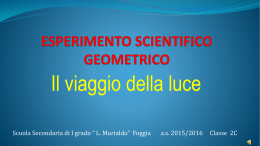
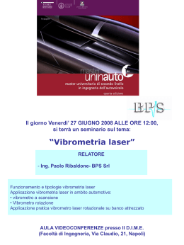
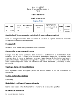
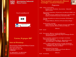
Controllo delle superfici di
prodotti in pietra naturale
di Michele Lanzetta, Giovanni Tantussi
Dipartimento di Ingegneria Meccanica, Nucleare e della Produzione
Università degli studi di Pisa, Italia
1. BASE DI PARTENZA SCIENTIFICA NAZIONALE O
INTERNAZIONALE
Se si esaminano i dati statistici relativi alla lavorazione
di materiali lapidei e alla produzione di macchinari con
particolare riferimento allo sbilanciamento tra esportazioni e importazioni, emerge chiaramente la leadership
tecnologica del nostro paese a livello mondiale.
L'enorme crescita della concorrenza soprattutto ad opera
dei paesi emergenti impone, però, di adottare politiche
di innovazione atte a mantenere tale ruolo per il sistema
paese. La visione artificiale è nata con la robotica negli
anni settanta e si è sviluppata in maniera crescente nel
campo della robotica industriale e dell'automazione negli
ultimi due decenni. Le prime massicce applicazioni sono
avvenute nell'industria elettronica. Con la rapida evoluzione delle tecnologie dell'informazione, questi sistemi
stanno diventando sempre più interessanti per un numero crescente di applicazioni industriali e, oggi, rappresentano un settore di punta nel campo della produzione.
Tra i sensori impiegati nell'industria, i sistemi di visione
artificiale sono quelli di impiego più generale e sono
strumenti flessibili che possono automatizzare con successo una delle più potenti capacità sensoriali dell'uomo.
Vengono impiegati favorevolmente nella maggior parte
delle operazioni produttive per controllo (ad esempio in
ausilio di robot) e controllo di qualità (ad esempio per
verificare la correttezza e correggere il risultato di operazioni precedenti). Tra le principali funzioni di tipo visivo vi sono: riconoscimento, misura, localizzazione e
inseguimento. Nel montaggio, che rappresenta circa
l'80% di tutte le operazioni industriali, i sistemi di visione sono correntemente utilizzati per rilevare presenza
/assenza, identificazione, corretto assemblaggio, incol-
SURFACE CONTROL
OF NATURAL STONE
PRODUCTS
by Michele Lanzetta, Giovanni Tantussi
Department of Mechanical, Nuclear and
Production Engineering
University of Pisa, Italy
Schema tecnico del riflettometro sviluppato
Scheme of the developed reflectometer
1. NATIONAL AND INTERNATIONAL SCIENTIFIC
BACKGROUND
Examining the statistics related to the processing of stone
materials and the manufacture of machinery, with special
reference to imbalance between exports and imports, it
is clear the worldwide technological leadership of our
country. However the enormous increasing competition,
especially by emerging countries, requires to adopt
innovative approaches in order to keep this leading role.
Artificial vision was born together with robotics in the
seventies and it has increasingly developed in the field of
industrial robotics and automation over the last two
decades. The first large-scale applications were made in
electronics industry. With the rapid evolution of information
technology, these systems are becoming more interesting
for a growing number of industrial applications and today
they represent an important factor in production activities.
Among the most used sensors in industry, artificial vision
systems have a more general use and are flexible tools
able to successfully automate one of the most powerful
sensory capabilities of man. They are used favourably in
most manufacturing operations for control (e.g. using
robots) and quality control (e.g. to check accuracy and
correct the result of previous operations). Among the main
visual functions we include: recognition, measurement,
localization and tracking. In the assembly, which represents
about 80% of all industrial operations, vision systems are
currently used to detect the presence / absence, identification,
proper assembling, gluing and sealing and quality control,
laggio, sigillatura e controllo di qualità, che è una
delle più diffuse applicazioni sia in campo meccanico,
sia elettronico. Attualmente, la frontiera nel campo
della ricerca sulle applicazioni dei sistemi di visione è
rappresentata da:
- studio di sistemi integrati, per ridurre la complessità
dell'hardware incorporando sempre maggiori funzioni a
bordo dei sensori;
- miniaturizzazione, per aumentare la versatilità delle
applicazioni nel caso di esigenze di ingombro limitato;
- visione tridimensionale (3D), la maggior parte delle
applicazioni industriali sono di tipo 2D e non esistono
ancora algoritmi consolidati che risolvano definitivamente il problema, né tantomeno prodotti commerciali;
- applicazione a lavorazioni non tradizionali. Nel campo
della ricerca, come in campo industriale, oggi la potenza disponibile consente l'implementazione di algoritmi
più complessi che permettono di trattare la variabilità e
imprevedibilità dei prodotti naturali.
È in quest'ultimo settore che si colloca la ricerca affidata all'Unità di Pisa. I problemi aperti riguardano essenzialmente la definizione di parametri oggettivi che possano essere correlati con i risultati delle lavorazioni
superficiali su materiali lapidei, e lo sviluppo dei metodi
per la loro determinazione sperimentale.
In [AS98I] è stata fornita una classificazione delle
applicazioni della visione tridimensionale ai processi di
produzione e indicata una rassegna delle principali tecniche utilizzate. Questa analisi critica di circa 50 articoli, unitamente alla bibliografia citata nelle altre pubblicazioni prodotte presso il DIMNP, fornisce un'ampia
panoramica dello stato dell'arte nel campo dei controlli
which is one of the most popular applications in both
mechanical and electronic field. Currently the frontier in
vision system applications research is represented by:
- study of integrated systems, to reduce hardware complexity
incorporating more and more functions embedded into
the sensors;
- miniaturization, to increase versatility of applications in
case of limited space requirements;
- three-dimensional (3D) vision, most industrial applications
are 2D type and neither consolidated algorithms nor
commercial products exist to solve the problem definitely;
- application to non-traditional machining operations.
In research, as in industrial field, the power available
today allows the implementation of more complex
algorithms that can manage the variability and
unpredictability of natural products.
In this latter area has been conducted the research
involving the University of Pisa. The open problems
mainly concern the definition of objective parameters that
can be correlated with the results of stone material
surface processing, and the development of methods for
their experimental determination.
In [AS98I] a classification of 3D vision applications for
production processes is shown as well as a review of the
main techniques used. This critical analysis of about 50
papers, together with the literature cited in other publications produced at the DIMNP, provides a broad overview
of the state of the art in artificial vision.
The joint project was conducted by the Research Units
di visione artificiale. Il progetto è stato condotto in collaborazione con le Unità di Ricerca (UR) della Università
di Cassino (coordinatore del progetto), dell'Università
de L'Aquila e del Politecnico di Milano.
1.1 COMPETENZE GIÀ SVILUPPATE PRESSO L'UNITÀ DI RICERCA (UR)
Il Dipartimento di Ingegneria Meccanica, Nucleare e
della Produzione (DIMNP) vanta una prolungata e diversificata esperienza nelle applicazioni dei sistemi di visione artificiale in campo industriale, realizzate presso il
proprio laboratorio di Visione Industriale. Una rassegna
di tali realizzazioni è stata presentata nella forma di
Technical Report al Scientific and Technical Committee
Assembly (STC “A”) del Cirp [Cirp01SV].
1.1.1 CONTROLLO DI PRODOTTO TRAMITE VISIONE ARTIFICIALE
Presso il DIMNP è stato svolto uno studio, che si
potrebbe definire pionieristico, che ha portato alla realizzazione del prototipo di un sistema di visione per la
classificazione di piastrelle di marmo compiuta sia con
un approccio di tipo statistico, sia facendo uso di reti
neurali [5], [Carrara95]. Tale studio è stato poi esteso
ad altri materiali lapidei come il granito [Carrara00] e
all'analisi dei difetti [4], [Carrara97]. Nel campo dei
controlli su parti meccaniche, presso il DIMNP, sono
state curate diverse applicazioni in tutti i casi sviluppando algoritmi originali, quali:
1. presenza/assenza o scambi di componenti di serrature per automobili;
2. misure di pezzi stampati [Amst99VS];
3. controllo di integrità e eventuale presenza di difetti
dovuti al processo produttivo su o-ring [Mrq98];
(RUs) of University of Cassino (project coordinator),
University of L'Aquila and Politecnico di Milano.
1.1 SKILLS ALREADY DEVELOPED AT THE RESEARCH UNIT (RU)
The Department of Mechanical, Nuclear and Production
Engineering (DIMNP) boasts a long and varied experience
in applications of artificial vision systems in industrial
field, thanks to its laboratory of Industrial Vision.
A review of these achievements was presented in the
form of technical report to the Scientific and Technical
Committee Assembly (STC “A”) of the CIRP [Cirp01SV].
1.1.1 PRODUCT INSPECTION BY ARTIFICIAL VISION
A pioneer study was conducted at DIMNP and it led to
the creation of a prototype vision system for the classification
of marble tiles accomplished by both statistical approach
and use of neural networks [5], [Carrara95].
This study was then extended to other stone materials
such as Granite [Carrara00] and to the analysis of
defects [4], [Carrara97]. In the field of inspections of
mechanical parts different applications were made, in all
cases developing original algorithms, such as:
1. presence/absence or change of lock components for
automobiles;
2. measures of moulded parts [Amst99VS];
3. integrity check and eventual presence of defects due
to o-rings production process [Mrq98];
4. ball bearings [Prime01VS] with a vision system, in
co-operation with Magna, Siemens and SKF;
4. cuscinetti a sfera [Prime01VS] con un sistema di
visione, rispettivamente in collaborazione con Magna,
Siemens e SKF.
5. controllo di qualità sulla pelle per la rifilatura, sull'argomento sono stati attivati due progetti finanziati dalla
Fondazione Cassa di Risparmio di Pisa [Atti08] e dalla
UE programma Cornet.
1.1.2 CONTROLLO DEI PROCESSI DI LAVORAZIONE TRAMITE
VISIONE ARTIFICIALE
Le tecniche di visione artificiale sono state applicate
anche ad una pluralità di processi come ausilio per
l'automazione e il controllo, di cui vengono elencate le
più significative.
- Per le operazione robotizzate assistite tramite visione
artificiale in campo tridimensionale è necessaria l'implementazione di sofisticati modelli per la descrizione della
configurazione geometrica e del comportamento dei
diversi componenti del sistema di visione (telecamera/e,
lenti, ecc.). In [AS98II] sono stati proposti due metodi
per la localizzazione basati su approcci radicalmente
diversi: il primo con reti neurali e singola telecamera, il
secondo, sviluppato in collaborazione con l'Università di
Stanford, per risolvere il problema delle corrispondenze
tra immagini stereo.
- È stato sviluppato e applicato un metodo di calibrazione e localizzazione tridimensionale stereo basato su reti
neurali [AS96] e la relativa estensione al caso di tre
telecamere [Elot96]. Tale sistema opera in tempo
reale ed è in grado di ricostruire la posizione nello spazio dell'oggetto osservato.
- Con particolare riferimento al montaggio, è stato pro-
5. quality control of skin for trimming; two projects funded
by Fondazione Cassa di Risparmio di Pisa [Atti08] and
EU Cornet program.
1.1.2 CONTROL OF MANUFACTURING PROCESSES BY
ARTIFICIAL VISION
The artificial vision techniques have also been applied to
a plurality of processes to assist in automation and control
and the most significant are listed hereunder:
- For robotic operation assisted by artificial vision in 3D
field it is needed to implement sophisticated models for
describing the geometric configuration and behaviour of
different components of the vision system (camera/s,
lenses, etc.). In [AS98II] two methods have been proposed
for localization, based on radically different approaches:
the first with neural networks and single camera, the
second, developed in collaboration with the University of
Stanford, to solve the problem of matching stereo images.
- A stereo 3D method of calibration and localization has
been developed and applied based on neural networks
[AS96] and its extension to the case of three cameras
[Elot96]. This system operates in real time and it is able to
reconstruct the position in the space of the observed object.
- With particular reference to assembly, an integrated
system between a force sensor and a vision sensor for
the peg-in-hole problem was proposed [Icme98].
- In [Amst96] a method was proposed to increase accuracy
in detecting the position of objects in 3D motion along
paths known before.
posto un sistema integrato tra un sensore di forza e di
visione, per il problema peg-in-hole [Icme98].
- In [Amst96] è stato proposto un metodo per aumentare la precisione nel rilevamento della posizione di oggetti
in 3D in moto lungo traiettorie note a priori.
- In [Adm97] viene descritto un metodo semplice per
l'acquisizione di profili bidimensionali da prototipi in
legno al fine di programmarne il ciclo di lavorazione alle
macchine utensili.
Nell'ambito del Progetto Nazionale biennale SPI, è stato
realizzato presso il DIMNP un sistema di controllo online di saldature per una cella automatizzata [Aitem99].
Sono state curate, inoltre, numerose esperienze nel
campo del controllo dello stato dell'utensile per lavorazioni meccaniche (TCM) [Ampt99] [Iwk96].
1.1.3 LAVORAZIONI DI MATERIALI LAPIDEI
Nel precedente Cofin 2001 l'UR di Pisa ha sviluppato un
prototipo di macchina di prova per perline diamantate
che ha permesso di realizzare in laboratorio test per la
determinazione delle condizioni ottimali di taglio con filo
diamantato [ROC03] [Aitem03] [Aitem].
2. DESCRIZIONE DELLA RICERCA ESEGUITA E DEI
RISULTATI OTTENUTI
I principali temi affrontati nel corso della ricerca sono stati:
- analisi con metodi ottici di superfici lucidate;
- caratterizzazione delle superfici con diverse metodologie;
- incisione di codici su materiali lapidei.
2.1 ANALISI CON METODI OTTICI DI SUPERFICI LUCIDATE
Lo studio ha riguardato l'applicazione di metodi ottici,
- In [Adm97] a simple method was described for the
acquisition of 2D profiles from wooden prototypes to plan
the machining cycle. Under the biennial National Project
SPI, a welding on-line control system for an automated
cell was carried out at DIMNP [Aitem99]. Many experiences
were also treated in monitoring of machining tool (TCM)
[Ampt99] [Iwk96].
1.1.3 STONE MATERIAL MACHINING
In the previous COFIN 2001, the Pisa RU has developed
a prototype test machine for diamond beads that allowed
to perform laboratory tests for determining the optimum
diamond wire cutting conditions [ROC03] [Aitem03] [Aitem].
2. DESCRIPTION OF THE RESEARCH AND RESULTS
The main issues addressed during the research were:
- analysis of polished surfaces with optical methods
- characterization of surfaces with different methods
- code engraving on stone materials.
2.1 ANALYSIS OF POLISHED SURFACES WITH OPTICAL METHODS
The study focused on the application of optical methods,
based on the analysis of the reflected rays on a surface
at different stages of processing and on the correlation
between these data and surface characteristics (mainly
roughness) of samples of stone material at different
stages of processing. The main aesthetic feature of a
polished stone product is the shine. The study showed a
theoretical and experimental link between the reflectance
DIAMANTE Applicazioni & Tecnologia
45
basati sull'analisi dei raggi riflessi su una superficie a
vari livelli di lavorazione e sulla correlazione fra tali dati
e le caratteristiche superficiali (essenzialmente la rugosità) di campioni di materiale lapideo a diversi gradi di
lavorazione. La principale caratteristica estetica di un
manufatto in materiale lapideo lucidato è la lucentezza.
Lo studio ha dimostrato un legame teorico e sperimentale tra la riflettanza (parametro quantitativo direttamente legato alla frazione di luce riflessa in direzione
speculare) e la finitura superficiale ottenuta con una
data lavorazione di lucidatura. I campioni sono stati
soprattutto forniti dall'Unità di Cassino, ma l'indagine è
stata applicata anche a vari tipi di materiali reperiti sul
mercato. Per quanto riguarda la dipendenza dalla rugosità del rapporto tra luce riflessa e luce incidente, l'analisi bibliografica ha evidenziato due relazioni teoriche:
1. la prima valida per Rq molto minore della lunghezza
d'onda della luce incidente;
2. la seconda, derivante dagli studi sul rendering delle
superfici generate al calcolatore, mostra l'intensità della
luce in una direzione in funzione della giacitura del
piano, dell'angolo di incidenza e della rugosità prevista
per una data direzione.
2.1.1 IL RIFLETTOMETRO
Per la verifica delle relazioni ed in generale per gli studi sperimentali sulla riflettometria, è stata messa a punto un'apparecchiatura per l'esecuzione di analisi
riflettometriche su campioni di piastrelle
in materiale lapideo a diversi gradi di
finitura superficiale (Rk < 4 micron).
Tale dispositivo, realizzato in diverse configurazioni, è uno dei principali risultati
del progetto.
2.1.1.1 PRIMO PROTOTIPO: RIFLETTOMETRO BASATO
SU SORGENTE DI ILLUMINAZIONE VISIBILE
Gli strumenti adoperati nella ricerca sperimentale, posizionati all'interno di una
cella di acquisizione, appositamente realizzata per l'ottenimento di un ambiente
d'analisi isolato e controllato, è composta
Profili di rugosità (non filtrati) per diversi tipi di lapidei
Unfiltered roughness profiles for different stone types
2.1.1 THE REFLECTOMETER
Esempio di superficie lapidea digitalizzata relativa ai campioni precedenti.
Si denotano chiaramente i picchi negativi tipici di una superficie a plateau
Example of stone digital surface for the samples above. Negative peaks are clearly
visible, showing a plateau-like behaviour
For the verification of relations and in general
for the experimental studies on reflectometry,
an equipment has been developed for
performing reflectrometry analysis on
samples of stone material tiles at different
stages of surface finish (Rk < 4 microns).
This device, available in different configurations, is one of the major project results.
2.1.1.1 FIRST PROTOTYPE: A REFLECTOMETER
BASED ON A VISIBLE LIGHT SOURCE
(quantitative parameter directly related to the fraction of
light reflected towards a mirror) and the surface finishing
obtained by different polishing techniques.
Samples were mainly supplied by the Unit of Cassino,
but the investigation has also been applied to various
types of materials available on the market.
Regarding dependence of the relationship between
reflected light and incident light from the roughness,
the literature review has highlighted two theoretical
relationships:
1. the first one is valid for a much smaller Rq than the
wavelength of the incident light;
2. the second one, deriving from studies on the
rendering of surfaces generated by the computer, shows
the intensity of the light in a direction depending on
the attitude of the plane, the incidence angle and the
foreseen roughness for a given direction.
The instruments used in the experimental
research, placed inside an acquisition cell specially
designed for obtaining an isolated and controlled environment for analysis, consists of a coherent light source
(He-Ne laser with a wavelength of 633 nm) of 6 mW and
a receptor positioned to receive the reflected rays from
the samples. The receptor is a high performance camcorder, with CCD sensor, monochrome (8 bits) connected to a computer through an A/D dedicated card. The
camera used for this study has a standard CCIR with
768 x 576 pixel resolution and f/32 aperture and 80 mm
focal length lenses. The light source was attenuated with a
97% filter. The instrumentation used for the
reflectometry analysis was placed on a modular aluminium
equipment specially designed for precise adjustment of
the angles of the inspection ray and the matrix sensor.
The axis of the incident laser beam is placed each time
at a specified epsilon angle referred to the perpendicular
da una fonte di luce coerente (laser He-Ne con lunghezza d'onda di 633 nm) da 6 mW ed un recettore posizionato per ricevere i raggi riflessi dai campioni.
Il recettore è una videocamera ad alte prestazioni, con
sensore CCD, monocromatica (8 bit) connessa ad un
calcolatore per mezzo di una scheda A/D dedicata.
La videocamera utilizzata per questo studio ha uno standard CCIR con risoluzione 768x576 pixel e su di essa è
montato un treno di lenti con diaframma f/32 e lunghezza focale di 80 mm. La fonte luminosa è stata attenuata
con un filtro al 97%. La strumentazione adoperata per
l'analisi riflettometrica è stata posizionata su una attrezzatura modulare in alluminio appositamente realizzata
per la regolazione precisa degli angoli di posizionamento
del raggio di ispezione e del sensore matriciale. L'asse
del raggio laser incidente viene posizionato di volta in
volta ad uno specificato angolo epsilon riferito alla perpendicolare alla superficie del campione. L'asse del
recettore viene regolato di conseguenza in posizione
speculare rispetto all'asse del raggio incidente. Con questa tecnica la quantità di luce riflessa delle immagini
acquisite viene valutata a livello di pixel usando software
ed hardware specifici per l'image processing.
operante nel range: 700-1800 nm. Questa configurazione, di maggiore costo, oltre alla maggiore versatilità,
consente di estendere il campo di indagine anche a
campioni aventi valori di rugosità più elevati.
Ad esempio, tale dispositivo, se inserito in una macchina
di lucidatura multiteste, consente un controllo anche in
fasi intermedie del processo.
2.1.1.2 SECONDO PROTOTIPO: RIFLETTOMETRO BASATO SU SORGENTI
DI ILLUMINAZIONE INTERCAMBILI NIR
In base ad un'analisi spettrofotometrica (dettagliata di
seguito) sono emersi i vantaggi connessi con l'impiego
di sorgenti ad elevata lunghezza d'onda per la caratterizzazione di materiali lapidei. In particolare, sono stati
impiegati 4 diodi Laser Ø 5.6 mm con lunghezze d'onda
nel vicino infrarosso (NIR) pari a: 785-980-1310-1550
nm e come sensore un Optical Beam Analyzing System
Sono stati analizzati:
- piastrelle in Breccia Sarda Chiara a dodici stadi di lavorazione (gli ultimi tre di lucidatura, gli altri di finitura e
sgrossatura);
- tre diversi tipi di Coreni (Nocciolato, Perlato e Mezza
Perla) a tre stadi di lavorazione (forniti dall'Unità di
Ricerca dell'Università di Cassino);
- quattro diversi tipi di Marmi all'ultimo stadio di lucidatura;
- tre diversi tipi di Graniti all'ultimo stadio di lucidatura;
to the sample surface. The receptor axis is adjusted
accordingly in a mirror position on respect to the axis of
the incident ray. With this technique the amount of the
light reflected by the acquired images is evaluated at the
pixel level using image processing specific software and
hardware.
using a controlled handling of the device and/or of the
artefact to be examined. The system, with 3 controlled
axes, provides various configurations (with mobile reflectometer and fixed artefact, and vice versa) and allows to
set the strategy for the automatic acquisition at uniformly
distributed points on the surface to check.
2.1.1.2 SECOND PROTOTYPE: A REFLECTOMETER BASED ON NIR
2.1.1.4 EXPERIMENTAL TESTS
INTERCHANGEABLE LIGHT SOURCES
According to spectrophotometric analysis (detailed below)
the advantages have been showed associated with the
use of sources with high length wavelength for the
characterization of stone materials. In particular four
5.6 mm Ø laser diodes have been used with wavelengths
in the near infrared (NIR) equal to: 785-980-1310-1550
nm and an Optical Beam Analyzing System as a sensor
operating in the range of 700-1800 nm.
This higher cost configuration, in addition to a greater
flexibility, extends the research field for samples with
higher roughness values. For example, this device, when
inserted in a multi-head polishing machine, allows any
check in intermediate stages of the process.
2.1.1.3 THIRD PROTOTYPE: AN ENGINEERED REFLECTOMETER
In collaboration with the Unit of Cassino a compact
version of the second type of reflectometer was made
with a single optimized NIR illumination source based
on the results of the tests executed with the second
prototype. Different configurations have also been developed
to run repeated measurements on samples automatically,
2.1.1.3 TERZO PROTOTIPO: RIFLETTOMETRO INGEGNERIZZATO
In collaborazione con l'Unità di Cassino è stata realizzata
una versione compatta del secondo tipo di riflettometro
con singola sorgente di illuminazione NIR ottimizzata in
base ai risultati delle prove svolte con il secondo prototipo. Sono state, inoltre, sviluppate diverse configurazioni
per l'esecuzione in automatico di misure ripetute su
campioni, tramite una movimentazione controllata del
dispositivo e/o del manufatto da esaminare. Il sistema,
a 3 assi controllati, prevede diverse configurazioni (con
riflettometro mobile e manufatto fisso e viceversa) e
consente di impostare la strategia per l'acquisizione
automatica in punti uniformemente distribuiti sulla
superficie da controllare.
2.1.1.4 PROVE SPERIMENTALI
The following samples were analyzed:
- Breccia Sarda Chiara tiles at twelve stages of processing
(last three of polishing, other of finishing and roughing);
- three different types of Coreno (Nocciolato, Pearl and
Half Pearl) at three processing stages (supplied by the
Research Unit of the University of Cassino);
- four different types of marble at the last stage of polishing;
- three different types of granite at the end polishing stage;
- a sample of Travertine at the last stage of polishing.
The acquisitions were made using angles of incidence
ranging from 10° to 80° at intervals of 10°, and even at
85°. For each incidence angle and for each sample the
captured images were seven: the first was used for
checking the focusing of the space frame and the dimensioning of the detection field; the second was the beam
image reflected by a high precision mirror (99.7% of
reflection) on the sensor for the calibration of the system
(image is taken as a reference for comparison with the
remaining five ones), the latest five ones represented the
images of the reflected beam, at five different points, from
the sample to the sensor.
Two test campaigns were performed:
DIAMANTE Applicazioni & Tecnologia
47
- un campione di Travertino all'ultimo stadio di lucidatura.
Le acquisizioni sono state effettuate utilizzando angoli
di incidenza variabili da 10° a 80°, ad intervalli di 10°,
ed anche a 85°. Per ogni angolo di incidenza e per ogni
campione le immagini catturate sono state sette: la
prima è impiegata per la verifica della messa a fuoco
dello spazio da inquadrare e il dimensionamento del
campo di rilevamento; la seconda rappresenta l'immagine del fascio riflesso da uno specchio ad alta precisione (99,7% di riflessione) sul sensore per la taratura del
sistema (immagine che viene presa come riferimento
per il confronto con le rimanenti cinque); le ultime cinque rappresentano le immagini del fascio riflesso, in
cinque punti diversi, dal campione al sensore.
Sono state eseguite due campagne di prova:
1. nel primo caso è stato mantenuto un angolo di incidenza
fisso e sono state eseguite rilevazioni su campioni dello
stesso materiale, ma con finitura superficiale differente;
2. nel secondo caso le rilevazioni sono state eseguite
mantenendo lo stesso campione, ma variando l'angolo
di incidenza del laser.
relazione tra le prove sperimentali e gli aspetti teorici
dei fenomeni ottici. Bisogna tenere presente che tale
equazione è valida solo per valori di rugosità Rq inferiori almeno di un ordine di grandezza rispetto alla lunghezza d'onda del raggio incidente. Poiché, nella maggior parte dei casi, la rugosità delle superfici dei materiali lapidei a vari stadi di lucidatura supera il valore di
0.1 micron, l'analisi teorica può essere impiegata solo
in casi particolari come per la super-lucidatura dei
marmi (es. lastre di Marmo di Carrara per rivestimento
Ra=0.01 e Rq=0.052). L'indagine ha permesso di identificare per ogni condizione l'angolo di incidenza ottimale per cui si ha la massima sensibilità.
Dall'ampia sperimentazione è scaturito che:
- è necessario utilizzare sorgenti ad elevata lunghezza
d'onda per estendere il campo di indagine ad elevati
valori di rugosità - per materiali traslucidi, come la
maggior parte dei materiali lapidei, l'angolo di incidenza
deve essere elevato (>45°).
L'impiego del secondo prototipo di riflettometro ha per-
2.1.1.5 RISULTATI OTTENUTI CON
L'USO DEI RIFLETTOMETRI
Il confronto della caratteristica dell'intensità di luce
riflessa, ottenuta con il
primo prototipo di riflettometro, con la curva estrapolata dalle caratteristiche
della prima equazione teorica, trova una buona cor-
1. in the first case a fixed
angle of incidence was kept
and measurements were
Interazione tra radiazione luminosa e superficie colpita
Interaction between light radiation and hit surface
performed on samples of
the same material, but with
different surface finishing;
2. in the second case the measurements were performed - for translucent materials, like most of the stone materials,
the incidence angle must be high (> 45°).
keeping the same sample but varying the incidence
The use of the second prototype of reflectometer has led
angle of the laser.
to the following results:
2.1.1.5 RESULTS OBTAINED USING THE REFLECTOMETERS
- improving of the mechanical equipment to facilitate
The comparison of the characteristic of the reflected light both the rapid placement of the angles of incidence
intensity, obtained with the first prototype reflectometer,
and reflection and the proper reference between the
with the curve extrapolated from the characteristics of
reflectometer and the surface that requires high precision;
the first theoretical equation, is a good correlation
- the use of different sources in the near infrared range
between the experimental tests and the theoretical
to improve the sensitivity of the equipment.
aspects of the optical phenomena. It must keep in
The parameter measured by the reflectometer is the
mind that this equation is valid only for values of Rq
reflectance, of which the theoretical expression from the
roughness lower at least an order of magnitude compared
literature is known as a function of: material properties
to the wavelength the incident ray. Since, in most cases,
(refractive index) and surface (surface finishing) and
the surface roughness of stone materials in various
instrument configuration (angle of incidence of the light
stages of polishing exceeds the value of 0.1 microns, the ray). The comparison between the measurements and
theoretical analysis can be used only in particular cases
the data related to the material (measured as indicated
as for the super-polishing of marbles (e.g. Carrara
below) showed a good agreement with the theoretical
marble slabs for covering Ra = 0.01 and Rq = 0.052).
model. The test campaign allowed to determine the
The survey has identified the optimal incidence angle for
configuration of the tool for maximizing the sensitivity of
each condition for which we have the maximum sensitivity.
the instrument and extend the measurement range of
From the large trial, it emerged that:
roughness, characterized by the Rk parameter.
- you must use sources with high wavelength to extend
The results of this study have been patented with the
the field of investigation to higher values of roughness;
support of the University of Pisa n° PI/2007/A/000105,
messo di conseguire i seguenti risultati:
- miglioramento dell'attrezzatura meccanica per facilitare
sia il rapido posizionamento degli angoli di incidenza e di
riflessione che il corretto riferimento tra il riflettometro e
la superficie che richiede un'elevata precisione;
- l'impiego di diverse sorgenti nel campo del vicino infrarosso per migliorare la sensibilità dell'apparecchiature.
Il parametro misurato dal riflettometro è la riflettanza, di cui
è nota l'espressione teorica dalla letteratura in funzione di:
- caratteristiche del materiale (indice di rifrazione) e
della superficie (finitura superficiale);
- configurazione dello strumento (angolo di incidenza del
raggio luminoso).
Il confronto tra le misure effettuate e i dati relativi al
materiale (rilevati come indicato di seguito) hanno
mostrato un buon accordo con il modello teorico.
La campagna di prove ha permesso di determinare la
configurazione dello strumento che consente di massimizzare la sensibilità dello strumento e di estendere l'intervallo di misura della rugosità, caratterizzata tramite il
parametro Rk. I risultati di questo studio sono stati
oggetto di brevetto con il supporto dell'Università di
Pisa, n° PI/2007/A/000105, data l'innovatività del dispositivo e l'interesse industriale.
2.1.2 CARATTERIZZAZIONE DI SUPERFICI A BASSA RUGOSITÀ
(RA < 4 MICRON)
2.1.2.1 CARATTERIZZAZIONE DELLE SUPERFICI CON METODI A CONTATTO
Tutti i campioni sono stati analizzati con il rugosimetro a
contatto presente in laboratorio al fine di avere un riferimento oggettivo relativo alle misure con i metodi ottici.
Sono state eseguite 20 acquisizioni per campione con
due the innovativeness of the device and the industrial
interest.
lunghezza d'onda di taglio di 0.08, prendendo in considerazione i parametri Ra, Rq, Rk, Rvk, Rpk, MR1 e MR2.
I parametri Rvk, Rpk, MR1 e MR2 non hanno dato risultati soddisfacenti. I parametri di rugosità Ra e Rq hanno
dato risultati simili, ma poco sensibili a piccole variazioni
di finitura superficiale. Il parametro Rk, che tiene conto
della forma del profilo superficiale, rispecchia con maggiore fedeltà le caratteristiche riflettometriche analizzate
precedentemente. Da un'analisi qualitativa delle superfici esaminate è emerso chiaramente che l'effetto delle
lavorazioni di lucidatura sulla maggior parte dei materiali
lapidei (ad eccezione del marmo) è quello di rimuovere
le creste delle asperità superficiali lasciando inalterate le
cavità presenti dovute alla microporosità. L'aspetto che
ne deriva è quello tipico di una superficie a plateau le
cui caratteristiche possono essere notoriamente meglio
espresse attraverso il parametro Rk. Per il rilievo dei
profili di rugosità, il rugosimetro è stato corredato con
un sistema di movimentazione a 3 assi controllati, per
l'acquisizione automatica di valori in diverse zone della
superficie da analizzare e per la scansione di tratti di
superficie tramite l'acquisizione di profili contigui.
2.1.2.2 ANALISI MEDIANTE GLOSSMETRO
I campioni dei lapidei sono stati analizzati anche con un
glossmetro commerciale, ad angolo speculare di 20°,
60° e 85°, che restituisce valori di brillantezza espressi
in GU secondo la normativa ASTM D 532-89. Questo tipo
di strumento è quello maggiormente adoperato nell'industria lapidea per la misura della lucentezza dei prodotti in pietra lucidati. Dalle acquisizioni effettuate è risultato che i valori in uscita dal glossmetro mostrano una
parts of the surface by the acquisition of contiguous profiles.
2.1.2.2 ANALYSIS BY GLOSSMETER
2.1.2 CHARACTERIZATION OF LOW SURFACE ROUGHNESS
(RA <4 MICRON)
2.1.2.1 SURFACE CHARACTERIZATION BY CONTACT METHODS
All the samples were analyzed with the contact roughness
instrument available at the laboratory in order to have a
reference objective relevant to the measures with the
optical methods. 20 acquisitions were performed per
sample with a wavelength of cut of 0.08, taking into
account the parameters Ra, Rq, Rk, Rvk, Rpk, MR1 and
MR2. The parameters Rvk, Rpk, MR1 and MR2 do not
have given satisfactory results. The roughness parameters Ra and Rq, gave similar results, but little sensitive to
small changes in surface finishing. The parameter Rk,
which takes into account the shape of the surface profile,
reflects more faithfully the previously analyzed characteristics reflectrometry. From a qualitative analysis of the
examined surfaces it became clear that the effect of
polishing operations on most stone materials (except
marble) is to remove the ridges of the surface asperities
leaving unchanged cavities due to microporosity.
The aspect that results from them is the typical one of a
plateau surface whose characteristics, as known, may be
best expressed by the parameter Rk. For the measurement
of the roughness profiles, the roughness measurement
instrument was provided with a 3- controlled axis motion
system by the automatic acquisition of values in different
zones of the surface to be analyzed for the scanning of
The stone samples were analyzed with a commercial
glossmeter, at a 20°, 60° and 85°mirror angle, which
returns values of brilliance expressed in GU in
accordance with the ASTM D 532-89 standard.
This type of instrument is the most used one in stone
industry for measuring the gloss of polished stone products.
From the executed acquisitions it was found that the
output values from the glossmeter show a very large
dispersion, especially for the incident 20° angle. Moreover
the instrument is not capable of performing analysis on
products with surface roughness greater than 0.1 µm.
The experimental analysis and the comparison with other
techniques have shown serious limitations in the use of
the instrument that from the other side was designed and
constructed to measure the brightness of other types of
surfaces (varnishes, metal surfaces, ceramics, etc.).
2.1.2.3 SPECTROPHOTOMETRIC ANALYSIS
An innovative use has been proposed of a high precision
spectrophotometer that embraces a 0.1-2.5 µm light
spectrum. The spectrophotometer allowed to objectively
evaluate the amount of light reflected, absorbed and
transmitted by the samples. The tests were performed
with a probe for optical fiber solids with a 1000 K white
light bulb lamp. The obtained results confirm and
guarantee a correlation between the reflected or absorbed
light and the surface condition of the samples.
DIAMANTE Applicazioni & Tecnologia
49
amplissima dispersione, soprattutto per l'angolo incidente di 20°. Inoltre, lo strumento non è in grado di
eseguire analisi su prodotti con rugosità superficiale
superiore allo 0.1 micron. L'analisi sperimentale e il
confronto con le altre tecniche hanno mostrato serie
limitazioni nell'utilizzazione dello strumento che, del
resto, è stato concepito e realizzato per misurare la
lucentezza di altri tipi di superfici (vernici, superfici
metalliche, ceramiche ecc.).
2.1.2.3 ANALISI SPETTROFOTOMETRICA
È stata proposta una utilizzazione innovativa di uno
spettrofotometro ad alta precisione che abbraccia uno
spettro di luce 0.1-2,5 micron. Lo spettrofotometro ha
consentito di valutare oggettivamente la quantità di
luce riflessa, assorbita e trasmessa dai campioni.
Le prove sono state eseguite con una sonda per solidi a
fibra ottica con lampada a bulbo da 1000°K a luce
bianca. I risultati ottenuti confermano e garantiscono
una correlazione tra luce riflessa o assorbita e lo stato
superficiale dei campioni. Lo spettrofotometro rileva
l'energia di Assorbanza/Riflettanza ed è in grado di
dare informazioni sulla composizione chimica dei materiali in esame. Molto utile per analisi comparative sperimentali, tuttavia questo strumento non è adatto per
controlli di processo on-line, ha tempi di elaborazioni
elevati, è poco pratico ed è molto costoso. Lo strumento ha comunque fornito utili indicazioni sulle lunghezze
d'onde da impiegare per l'analisi riflettometrica.
2.1.3 CARATTERIZZAZIONE DI SUPERFICI AD ELEVATA RUGOSITÀ
2.1.3.1 CARATTERIZZAZIONE DI SUPERFICI LAVORATE CON GETTO
D'ACQUA CON PROFILOMETRIA OTTICA
È stato realizzato un sistema per il rilievo di superfici
senza contatto basato su profilometria ottica.
Il sistema comprende:
- un sensore commerciale di misura della distanza fra il
sensore e la superficie ad elevata risoluzione (0,25 micron);
- un sistema di movimentazione a 3 assi controllati da
PC, realizzato con slitte motorizzate di elevata precisione.
Il sistema è stato validato tramite rugosimetro e permette di acquisire profili e porzioni di superficie.
Questo sistema è particolarmente adatto per l'analisi di
superfici ad elevata rugosità (Ra > 4 micron) come
quelle ottenute dall'Unità di Milano con lavorazione a
getto d'acqua. L'analisi consente la valutazione degli
effetti di diversi parametri del processo [ICDS08a].
2.1.3.2 RILIEVO DI ELEVATE PROTRUSIONI E CAVITÀ SUPERFICIALI
CON SISTEMA DI VISIONE E ILLUMINAZIONE STRUTTURATA
È stata sviluppata una tecnica innovativa per determinare la presenza di protrusioni e cavità superficiali
basata su un particolare tipo di illuminazione strutturata ideata ad hoc. Allo
scopo è stato realizzato un prototipo di
un sistema portatile con telecamera e
illuminatori in grado di rilevare la presenza di elementi di dimensione prestabilita
Ricostruzione computerizzata di superfici lavorate tramite idrogetto con abrasivo, acquisite
tramite profilometro ottico / Computerized reconstruction of abrasive waterjet processed
surfaces by optical profilometer
The spectrophotometer detects the absorption /
reflectance energy and can provide information on the
chemical composition of test materials. Very useful for
experimental benchmarking test analysis, however this
instrument is not suitable for on-line process controls, it
has high processing time, it is impractical and very
expensive. However the instrument has provided useful
information on the wavelengths to be used for the
reflectometry analysis.
2.1.3 CHARACTERIZATION OF HIGH ROUGHNESS SURFACES
2.1.3.1 CHARACTERIZATION OF WATER-JET MACHINED SURFACES BY
OPTICAL PROFILOMETRY
A system was made to measure surfaces without contact
based on optical profilometry. The system includes:
- a commercial sensor measuring the distance between
the sensor and the surface at high resolution (0.25 µm);
- a 3-axis motion system controlled by a PC built with high
precision motorized devices.
The system was validated by means of
roughness measurement instrument and
allows to capture profiles and portions of
the surface. This system is particularly
suitable for the analysis of high roughness
(Ra > 4 µm) surfaces as those obtained by
the Unit of Milan by water-jet machining.
The analysis allows the evaluation of the
effects of various process parameters
[ICDS08a].
2.1.3.2 SURVEY OF HIGH PROTRUSIONS AND SURFACE CAVITIES BY
VISION SYSTEM AND STRUCTURED LIGHTING
An innovative technique was developed to determine the
presence of protrusions and surface cavities based on
structured lighting system. For this a prototype was built
of a portable system with camera and lights able to
detect the presence of predetermined size elements and
it has been tested to detect surface irregularities with a
size between 0.3 and 0.5 mm on a 35x35 mm2 squared
area. Some students have also co-operated to this
development within an educational project (see credits).
The results of this developed particular technique are
patentable with the scope to market compact and low cost
devices for quality control.
2.1.3.3 THREE-DIMENSIONAL RECONSTRUCTION OF SURFACES BY
STEREOSCOPIC VISION
As part of an apprenticeship in Mechanical Engineering
has been developed an equipment for surface acquisi-
ed è stato testato per il rilevamento di irregolarità
superficiali di dimensioni comprese tra 0,3 e 0,5 mm su
un'area nquadrata di 35x35 mm2. Allo sviluppo hanno
collaborato anche alcuni studenti nell'ambito di un progetto didattico (vedere ringraziamenti). I risultati sono
suscettibili di brevettazione della particolare tecnica di
rilievo sviluppata che mira alla commercializzazione di
dispositivi compatti ed economici per il controllo di qualità.
2.1.3.3 RICOSTRUZIONE TRIDIMENSIONALE DELLE SUPERFICI CON
VISIONE STEREOSCOPICA
Nell'ambito di un tirocinio in Ingegneria Meccanica è
stata sviluppata un'attrezzatura per l'acquisizione di
superfici e sviluppato il relativo software per la ricostruzione 3D. Il sistema è basato su algoritmo di visione
stereoscopica. La coppia di immagini stereo viene ottenuta tramite traslazione del campione o della telecamera. Questo sistema è adatto per rilevare superfici molto
scabre (con escursioni superiori al millimetro).
2.2 INCISIONE DI CODICI SU MATERIALI LAPIDEI
Quest'attività, prevista ai fini di sviluppare metodi
per l'identificazione e la rintracciabilità dei manufatti in
materiale lapideo, prevede il
confronto delle tecnologie di incisione laser e con getto
d'acqua ad alta pressione su
provini di marmo di Carrara e perlato di
Coreno.
su Perlato di Coreno e marmo di Carrara per l'ottimizzazione dei seguenti parametri per incidere con adeguata
definizione solchi su una superficie in materiale lapideo:
potenza del laser, velocità di scansione, grado di umidità
del materiale.
Per quanto riguarda le prove eseguite dall'Unità di Pisa,
sono emerse le seguenti informazioni:
- con potenze minori di 3W: si ottiene la formazione di
zone termicamente alterate, ma non si ha alcuna asportazione di materiale;
- con potenze comprese tra 4 e 10W: la quantità di
materiale asportato cresce linearmente con il crescere
della potenza e tale aumento è particolarmente vistoso;
- con potenze maggiori di 10W: la quantità di materiale
asportato sembra essere praticamente costante all'aumentare della potenza applicata, anche se la curva risulta essere leggermente crescente.
Inoltre, è emerso che il materiale umido presenta una
maggior asportazione di materiale probabilmente a
causa delle particelle di acqua che, evaporando rapidamente, si espandono in maniera quasi esplosiva provocando la fratturazione del materiale. Questa sperimentazione, oltre a dimostrare la fattibilità del processo di
incisione di codici (a barre o alfanumerici) tramite laser,
permette di determinare i parametri necessari per
ottenere un solco di dimensioni prestabilite.
2.2.1 INCISIONE LASER DI MARMO DI CARRARA
Nelle sedi di Cassino e di Pisa sono stati
realizzati piani sperimentali rispettivamente
tion and its software for 3D reconstruction.
The system is based on stereo vision
algorithm. The pair of stereo images is
obtained by translation of the sample or of
the camera. This system is suitable to detect
very rough surfaces (with excursions higher
than one millimeter).
2.2 ENGRAVING CODES ON STONE MATERIALS
This activity, useful for identification and
traceability of stone materials, makes a
comparison between laser and high pressure
water-jet engraving technologies using Carrara and
Perlato di Coreno marble samples.
Strategia di acquisizione delle superfici lavorate tramite profilometro ottico
Parameters of the optical profilometer for the 3D surface acquisition
2.2.1 LASER ENGRAVING OF CARRARA MARBLE
At Cassino and Pisa laboratories experimental tests were
carried out respectively on Perlato di Coreno and Carrara
marble in order to optimize the main parameters to
engrave a stone surface: laser power, scanning speed
and moisture content of the material.
With regard to the tests conducted by the Unit of Pisa,
the following information have been showed:
- with power less than 3 W: formation of heat-affected
zones but no material removal;
- with power ranging from 4 to 10 W: the amount of material
removed increases linearly with power and this increase
is particularly striking;
- with power greater than 10 W: the amount of material
removed seems to be almost constant increasing applied
power, although the curve appears to be slightly increasing.
It was also showed that the wet material has a higher
material removal probably due to the water particles
that, evaporating rapidly, expand in an explosive manner
causing the material fracturing. Besides proving the
feasibility of code engraving process by laser (alphanumeric
or bar code), this experiment can determine the parameters
necessary to obtain a groove of fixed size.
2.2.2 IMPROVING THE READABILITY OF CHARACTERS ENGRAVED
CARRARA MARBLE
While laser treatment on dark stone materials produces
colour alterations such as to generate a high contrast
between the tracks produced by laser and the untreated
areas, allowing the engraving of high readable codes by
the common bar code scanners, this is not the case of
Carrara marble, where the traces show a poor contrast.
To improve the readability has been developed a
technique based on the application of pigments on the
marble surface dispersed in a liquid resin which after
BY LASER ON
DIAMANTE Applicazioni & Tecnologia
51
2.2.2 MIGLIORAMENTO DELLA LEGGIBILITÀ DI CARATTERI
INCISI CON LASER SU MARMO DI CARRARA
Mentre su materiali lapidei scuri il trattamento laser
produce alterazioni cromatiche tali da generare un elevato contrasto fra le tracce prodotte dal laser e le zone
non trattate, permettendo l'incisione di codici ad elevata leggibilità da parte dei comuni scanner per codici a
barre, questo non si verifica nel caso del marmo di
Carrara, in cui le tracce risultano scarsamente contrastate. Per migliorare la leggibilità è stata messa a punto
una tecnica che prevede l'applicazione sulla superficie
di marmo di pigmenti dispersi in una resina liquida che,
una volta essiccata, ancora stabilmente il pigmento al
materiale. Il successivo trattamento laser asporta il pigmento generando tracce altamente leggibili. La marcatura
può essere effettuata sia in positivo che in negativo.
ristiche di risoluzione;
- il laser di cui sopra con l'aggiunta di un reticolo di
diffrazione, che ha permesso di ottenere griglie con
passo inferiore a 0,1 mm.
Le immagini sono state acquisite ad altissima risoluzione (1 micron/pixel). Tale tecnica consente di evidenziare la curva deformata che è stata interpolata ed analizzata tramite l'estrazione di parametri geometrici.
Le tre tecniche citate possono essere applicate per la
ricostruzione di superfici ad elevata rugosità.
2.2.4 VALUTAZIONE TECNICHE DI INCISIONE LASER E GETTO D'ACQUA
L'analisi comparativa ha mostrato una maggiore penetrazione del getto d'acqua. Le tracce ottenute con laser
hanno mostrato contorni più regolari e definiti [ICDS08b].
2.2.5 CONTROLLO DI QUALITÀ DI CARATTERI INCISI
2.2.3 CARATTERIZAZIONE DI CARATTERI INCISI
Le norme ISO relative alla stampa di caratteri indicano i
requisiti per la leggibilità che rappresentano anche le
specifiche per i processi di incisione. Per la caratterizzazione dei solchi realizzati dalle Unità di Milano, Cassino
e Pisa è stato sviluppato da quest'ultima un sistema
basato su visione artificiale e illuminazione strutturata.
I metodi testati per la proiezione di pattern sui provini
sono:
- l'uso di un videoproiettore, che ha presentato una
buona flessibilità nella generazione delle griglie, ma
presentava una risoluzione di un ordine di grandezza
superiore a quella richiesta;
- un laser HeNe con lente cilindrica per la realizzazione
di una lama di luce, che ha mostrato analoghe caratte-
being dried firmly fix the pigment on the material.
The following laser treatment removes the pigment
generating highly readable patterns. Both positive and
negative marking can be executed.
2.2.3 CHARACTERIZATION OF ENGRAVED CHARACTERS
The ISO standards for characters printing indicate the
requirements for legibility that also represent specifications
for the engraving processes. For the characterization of
the grooves made by the Unit of Milan, Cassino and
Pisa, a system was developed based on artificial vision
and structured lighting. The proven methods for projecting
patterns on the specimens are:
- the use of a video-projector, which provided a good
flexibility in grid generation, but showed a resolution of
an order of magnitude higher than that required;
- a HeNe laser with a cylindrical lens to create a blade of
light, which showed similar resolution characteristics;
- the above laser by adding a diffraction grating, which
allowed to obtain grids with a pitch less than 0.1 mm.
The images were acquired at a very high resolution
(1 µm / pixel). This technique allows to highlight the
deformed curve that has been interpolated and analyzed
by the extraction of geometric parameters.
The three mentioned techniques can be applied for the
reconstruction of high roughness surfaces.
2.2.4 EVALUATION OF ENGRAVING LASER AND WATER-JET
TECHNIQUES
The comparative analysis showed a higher penetration
È stato realizzato un sistema di acquisizione di immagini con illuminazione radente, in grado di eseguire il
controllo di qualità e l'OCR sui manufatti incisi con i
diversi processi su superfici lucidate, insensibile alla
variabilità dei materiali. Tale sistema sarà facilmente
applicabile industrialmente una volta che il processo di
incisione di caratteri si sarà affermato, sia a scopo
decorativo sia per la rintracciabilità dei prodotti.
3. TRASFERIMENTO DEI RISULTATI INAMBITO
INDUSTRIALE
3.1 SISTEMA DI ACQUISIZIONE DI LASTRE LUCIDATE
L'azienda Eurogranit che svolge l'attività di lucidatura
nel comprensorio di Massa e Carrara ha dato incarico al
of the water-jet. The traces obtained by laser showed
more regular and defined contours [ICDS08b].
2.2.5 ENGRAVED CHARACTERS QUALITY CONTROL
An image acquisition system was made with oblique
lighting, capable of performing quality control and OCR
on artefacts engraved by the various processes on
polished surfaces, unaffected by material variability.
This system will be easily industrially adopted when
character engraving process will penetrate the market,
both for decoration and for product traceability.
3. TRANSFERRING RESULTS TO INDUSTRY
3.1 POLISHED SLABS ACQUISITION SYSTEM
Eurogranit, a company performing stone polishing activities
in the area of Massa and Carrara, has instructed the
Department to develop an on-line acquisition system
of processed slabs (about 2x3 m2).
The introduction of optical devices, although at a limited
sophistication level, is highly innovative for the industry
and represents a potential for spread of technology (by
imitation) for quality control by vision systems [MMC06].
4. PRODUCTS DEVELOPMENT
During the project several prototypes were made with
components already available from the Department
and/or purchased with research funds.
The prototypes had a dual function:
- they were used for the acquisition of parameters for
Dipartimento per lo sviluppo di un sistema di acquisizione on-line di lastre lavorate (ca 2x3 m2).
L'introduzione di dispositivi di tipo ottico, anche se a
livello di sofisticazione limitato, è altamente innovativo
per il settore e rappresenta una potenzialità di diffusione
della tecnologia (per imitazione) per il controllo di qualità con sistemi di visione [MMC06].
4. PRODOTTI DELLA RICERCA ESEGUITA
Nel corso del progetto sono stati realizzati numerosi
prototipi con componenti già disponibili presso il
Dipartimento e/o acquistati con i fondi della ricerca.
I prototipi realizzati hanno avuto una duplice funzione:
- sono stati impiegati per l'acquisizione dei parametri
necessari alla valutazione dei processi messi a punto dai
partner del progetto;
- come dimostratori per un auspicabile trasferimento in
ambito industriale, allo scopo di controllare i processi
relativi.
La descrizione dei vari prototipi, che hanno rappresentato la parte predominante degli sforzi di ricerca, è già
inquadrata al paragrafo 2.
Di seguito vengono elencati i prototipi realizzati con le
principali caratteristiche e scopi. Il prototipo di riflettometro, realizzato in tre versioni, è uno strumento innovativo. La versione basata su sistema di visione artificiale presenta potenzialità di impiego in ambito industriale,
data la semplicità del principio sfruttato per il progetto.
La versione NIR è essenzialmente da laboratorio ed è
utilizzabile per analisi future su materiali anche diversi
dai lapidei. La versione ingegnerizzata è finalizzata
all'impiego industriale ed è scaturita direttamente dal
evaluation of processes developed by the project
partners and
- as demonstrators for a desirable transfer into industry,
for controlling the related processes.
The description of the various prototypes, which were the
main core of the research efforts, was already framed in
paragraph 2. Hereunder are the prototypes with the main
characteristics and uses.
The prototype reflectometer, available in three versions, is
an innovative tool. The version, based on artificial vision
system, has a potential use in industry, due to the simplicity of the principle exploited for the project.
The NIR version is essentially a laboratory version and
it can be used for future analysis on materials other than
stone also. The engineered version is designed for
industrial use and has directly resulted from testing the
previous prototype on several samples.
The reflectometer has been also interfaced with a
handling configurable and numerical control system.
For the analysis of polished and treated stone surfaces by
laser and water-jet, two automated acquisition stations,
based on standard commercial components, were developed
but it was necessary to get a comparison between the
new innovative instrumentation and the established
methods of analysis.
The two devices are based respectively on:
- contact roughness instrument
- optical profilometer.
There have also been realized two vision systems
test del prototipo precedente su diversi campioni. Il
riflettometro è stato, inoltre, interfacciato con un sistema di movimentazione configurabile e a controllo numerico. Per l'analisi delle superfici in materiale lapideo,
lucidate e trattate tramite laser e getto d'acqua, sono
state messe a punto due stazioni automatizzate di
acquisizione basata su componenti commerciali che non
presentano particolari caratteristiche di innovazione, ma
che sono state necessarie per avere un riscontro oggettivo tra la strumentazione innovativa realizzata e metodologie di analisi consolidate. I due dispositivi sono
basati rispettivamente su:
rugosimetro a contatto e profilometro ottico.
Sono stati inoltre realizzati due sistemi di visione per il
rilievo di superfici con diversi range di rugosità, basati
rispettivamente su:
- visione monoculare con illuminazione a diverse sorgenti cromatiche per il rilievo di asperità di dimensione
prestabilita;
- visione stereoscopica per la mappatura di superfici
tramite matching.
Per il rilievo di incisioni sono state realizzate diverse
configurazioni di sistemi di visione con illuminazione
strutturata basati su videoproiettore, lama di luce laser
e reticolo di diffrazione. Con quest'ultimo è stata svolta
l'analisi completa dei provini realizzati dai partner.
È stato realizzato il prototipo di un sistema di acquisizione di immagini di lastre lucidate e la relativa archiviazione. Tale sistema è stato installato su linea di produzione
presso un'azienda che ha cofinanziato lo sviluppo.
È stato anche sviluppato un software per la realizzazione di mosaici (pre-posa virtuale) con le immagini dei
for the detection of surfaces with different ranges of
roughness based respectively on:
- monocular vision with different chromatic source
lighting for the measurement of fixed size asperities;
- stereoscopic vision for surfaces mapping by matching.
Different configurations vision systems with structured
lighting based on video projector, laser light blade and diffraction grating were made for the measurement of
engravings. With the latter was carried out a complete
analysis of the specimens made by the partners.
A prototype image acquisition system was made for
polished slabs and related archiving. This system was
installed on the production line at a company that has
supported the project.
A software for the creation of mosaics (virtual pre-laying)
with images of real objects was also developed.
An experimental innovative equipment was developed
to evaluate abrasiveness of stone materials based on
a rotating platform that supports the specimen and with a
tip subjected to a controlled force, whose wear is
evaluated by means of data acquisition.
5. ACKNOWLEDGMENTS
Eng. Santo Gentile of GDTech s.n.c. has collaborated
to the project for the development of the reflectometer.
We thank Diessechem s.r.l., Milan for assistance and
equipment used in spectrophotometric measurements.
The measuring system of the roughness was developed
by students Matteo Tanzini, Alessandro Serio, Simone
DIAMANTE Applicazioni & Tecnologia
53
manufatti reali. È stata messa a punto un'attrezzatura
sperimentale innovativa per valutare l'abrasività di
materiali lapidei basata su piattaforma rotante che supporta il provino e con un puntale sottoposto a forza
controllata di cui viene valutata l'usura tramite acquisizione dati.
5. RINGRAZIAMENTI
Al progetto ha collaborato l'Ing. Santo Gentile della
società GDTech s.n.c. per lo sviluppo del riflettometro.
Si ringrazia la società Diessechem s.r.l. di Milano per
l'assistenza e le attrezzature impiegate nelle misure
spettrofotometriche.
Il sistema di rilievo delle asperità è stato sviluppato
dagli studenti Matteo Tanzini, Alessandro Serio, Simone
Natali, Massimo Satler e Giuseppe Angotzi nell'ambito
del progetto didattico di Automazione dei Processi
Produttivi del Corso di Laurea Specialistica in
Ingegneria della Automazione, a.a. 2005-06.
Il sistema di visione per la ricostruzione stereo di
superfici scabre è stato sviluppato dallo studente
Daniele Ciomei nell'ambito del tirocinio del Corso di
Laurea in Ingegneria Meccanica. Si ringraziano inoltre:
- Ing. Marco Clemente, Ing. Camillo Scionti e Ing.
Giacinto Lombardi (tesi di laurea in Ingegneria
Meccanica del vecchio ordinamento);
- Sig.ra Federica Fanti (acquisizione di superfici scabre
tramite illuminazione strutturata), Ing. Guido Lenzi,
Ing. Alessandro Bernardelli (caratterizzazione di superfici scabre ottenute tramite lavorazione a getto d'acqua), Ing. Alessandro Maggesi (ingegnerizzazione del
riflettometro), Ing. Valerio Zambardi (sviluppo di un
sistema integrato a contatto e ottico per l'analisi di
superfici) - tirocini Corso di Laurea in Ingegneria
Meccanica.
Versione da laboratorio del riflettometro realizzato di cui al brevetto n. PI/2007/A/000105
Laboratory version of the developed reflectometer as in the Italian patent n. PI/2007/A/000105
Natali, Massimo Satler and Giuseppe Angotzi in the
educational project ‘Production Process Automation’ during the Master degree in Automation Engineering, year
2005-06. The vision system for the stereo reconstruction
of rough surfaces was developed by the student Daniele
Ciomei within the apprenticeship for the degree in
Mechanical Engineering.
We also thank:
- Eng. Marco Clemente, Eng. Camillo Scionti and
Eng. Giacinto Lombardi (thesis degree in Mechanical
Engineering, old course system).
- Ms. Federica Fanti (acquisition of rough surfaces by
means of structured lighting), Eng. Guido Lenzi,
Eng. Alessandro Bernardelli (characterization of rough
surfaces obtained by water-jet machining), Eng.
Alessandro Maggesi (engineering of the reflectometer),
Eng. Valerio Zambardi (development of an integrated
contact and optical system for surface analysis) training period of the course of degree in Mechanical
Engineering.
6. LITERATURE / RIFERIMENTI BIBLIOGRAFICI
[AS98I] Lanzetta, M.: Visione Tridimensionale nei Processi di
Produzione - “Stato dell'Arte”, Automazione e Strumentazione
Elettronica Industriale, ANIPLA, Associazione Nazionale
Italiana per l'Automazione, n°2, Anno XLVI, Febbraio 1998,
pag. 155-164.
[Cirp01SV] Lanzetta, M.: Industrial applications of artificial
vision in automated assembly, Technical Report presentato
personalmente al Scientific and Technical Committee
Assembly (STC “A”), 51st CIRP General Assembly, Nancy,
Francia, 19-25 Agosto, 2001.
[Carrara95] Tantussi, G.; Lanzetta, M.: Nuove Applicazioni
dell'Analisi di Immagini nel Settore dei Lapidei, Tecnolapidei
'95, Convegno su “La coltivazione in sotterraneo e la tutela
ambientale”, Carrara '95, XXVI Fiera Internazionale Marmi
Macchine e Servizi, Carrara, 20 Maggio 1995.
[Carrara00] Lanzetta, M.; Tantussi, G.: Sviluppo e Confronto
di Tecniche di Controllo di Qualità di Manufatti in Granito,
Articolo su invito, Atti del Convegno “Studi e indagini sui
materiali lapidei”, Carrara 2000, XXI Fiera Internazionale
Marmi, Macchine e Servizi, Ed. Tipografia Editrice Pisana,
Carrara, 3 Giugno, 2000, pag. 21-30.
[Carrara97] Tantussi, G.; Lanzetta, M.: Applicazioni dei
Sistemi di Visione per il Riconoscimento di Difetti nel Settore
Lapideo, Convegno su “La didattica e la ricerca per un nuovo
sviluppo della risorsa marmo. Sicurezza, ambiente, produttività”, Carrara '97, XVIII Fiera Internazionale Marmi, Macchine e
Servizi, Carrara, 25 Maggio 1997.
[Amst99VS] Lanzetta, M.; Tantussi, G.: Vision System
Calibration and Sub-Pixel Measurement of Mechanical Parts,
AMST'99, Atti del 5° Congresso Internazionale su “Advanced
Manufacturing Systems and Technology”, CISM Courses and
Lectures No. 406, Ed. E. Kuljanic, ISBN: 3-211-83148-7,
Springer-Verlag, Wien New York, Udine, 3-4 Giugno, 1999,
pag. 695-702.
[Mrq98] Lanzetta, M.: The Quality Control of Critical Assembly
Components: Visual Inspection of O-Rings, 2nd MRQ, Atti del
2° Congresso Internazionale su “Planned Maintenance,
Reliability and Quality”, Ed. G.J. McNulty, ISBN: 0 86339 7867,
Oxford, UK, 2-3 Aprile, 1998, pag.132-137.
[Prime01VS] Lanzetta, M.; Tantussi, G.; Santochi, M.: The
Process Control in Manufacturing: Inspection of Ball Bearings,
PRIME 2001, 1st International Seminar on “Progress in
Innovative Manufacturing Engineering”, Ed. P. M. Lonardo,
ISBN: 88-900559-0-1, Sestri Levante (GE), 20-22 Giugno,
2001, pag. 405-410.
[Atti08] Lanzetta, M., Dini, G., Tantussi, G., Failli, F., Sebastiani,
F., Gentile, S., Relazione Finale relativa alla Convenzione con
la Fondazione Cassa di Risparmio di Pisa nella ricerca denominata: Sviluppo e realizzazione di sistemi di manipolazione/movimentazione e controllo dei prodotti nel comparto della pelle nel
territorio pisano, Atti del Dipartimento di Ingegneria Meccanica,
Nucleare e della Produzione, n. 005 (2008), Università di Pisa,
30 Gennaio 2008, 93 pp.
[AS98II] Lanzetta, M.: Visione Tridimensionale nei Processi di
Produzione - Applicazioni, Automazione e Strumentazione
Elettronica Industriale, ANIPLA, Associazione Nazionale Italiana
per l'Automazione, n. 3, Anno XLVI, Marzo 1998, pag. 137-144.
[AS96] Lanzetta, M.: Visione Stereoscopica con Reti Neurali,
Automazione e Strumentazione Elettronica Industriale, ANIPLA,
Associazione Nazionale Italiana per l'Automazione, n. 7, Anno
XLIV, Luglio/Agosto 1996, pag. 107-116.
[Elot96] Lanzetta, M.: Calibrazione di un Sistema di Visione a
Tre Telecamere Tramite Reti Neurali, Elettroottica '96, Atti del IV
Convegno Nazionale “Strumentazione e Metodi di Misura
Elettroottici”, Milano, 29-31 Maggio, 1996, pag. 415-419.
[Icme98] Lanzetta, M.; Dini, G.: An Integrated Vision-Force
System for Peg-In-Hole Assembly Operations, ICME '98, CIRP
International Seminar on “Intelligent Computation in
Manufacturing Engineering”, Ed. R. Teti, Capri (NA), 1-3 Luglio,
1998, pag. 615-621.
[Amst96] Lanzetta, M.; Tantussi, G.: Monitoring Critical Points
in Robot Operations with an Artificial Vision System, AMST'96,
Atti del 4° Congresso Internazionale su “Advanced Manufacturing
Systems and Technology”, CISM Courses and Lectures N° 372,
Ed. E. Kuljanic, ISBN:3-211-82808, Springer-Verlag, Wien New
York, Udine, 2-3 Settembre, 1996, pag. 593-600.
[Adm97] Lanzetta, M.: Rasterisation of 2-D profiles with
Unlimited Resolution through Artificial Vision Techniques: an
Application to the Wood Industry, 10th ADM Conference, Atti del
10° Congresso Internazionale su “Design Tools and Methods in
Industrial Engineering”, Ed. Università di Firenze, ISBN: 88 7957
113-3, Firenze, 17-19 Settembre, 1997, pag. 311-316.
[Aitem99] Lanzetta, M.; Tantussi, G.; Santochi, M.: An
Approach to On-line Welding Control through an Artificial Vision
System, A.I.Te.M IV, Atti del IV Convegno della Associazione
Italiana di Tecnologia Meccanica, Brescia, 13-15 Settembre,
1999, pag. 501-509.
[Ampt99] Lanzetta, M.; Tantussi, G.: A Flexible High-Resolution
Vision Sensor for Tool Condition Monitoring, AMPT'99 and
IMC16, Proceedings of the International Conference “Advances
in Materials and Processing Technologies” and XVI Annual
Meeting of the Irish Manufacturing Committee, Dublin, Ireland,
3-4 August, 1999, vol. 1, pp. 569-593, Published by Dublin City
University, Editors Prof. M.S.J. Hashmi and Dr. L. Looney.
[Iwk96] Lanzetta, M.: Tool Condition Monitoring Using an
Artificial Vision System: Application of Blob Analysis to End
Mills, 41. Internationales Wissenchaftliches Kolloquium, Band
1, Ed. Technische Universitat Ilmenau, ISBN: 0943-7207,
Ilmenau, Germania, 23-26 Settembre, 1996, pag. 581-586.
[ROC03] Tantussi, G.; Lanzetta, M.; Romoli, V., A Multi-axis
Machine for Single Diamond Bead Testing, Roc MaquinaDimension Stone Industry, num. 51, pp. 30-33, 2003.
[Aitem03] Tantussi, G.; Lanzetta, M.; Romoli, V., Diamond Wire
Cutting of Marble: State of the Art, Modeling and Experiments
with a New Testing Machine, A.I.Te.M VI, Proceedings of the
6th International Conference of the Italian Association of
Mechanical Technology, Enhancing the Science of
Manufacturing, vol. Unico, pp. 113-126, Gaeta (LT), Italy 2003.
[Aitem] Carrino L., Di Ilio A.M., Monno M., Tantussi G.,
Turchetta S.: Manufacturing technologies of ornamental stones,
A.I.Te.M VI, Proceedings of the 6th International Conference of
the Italian Association of Mechanical Technology, Enhancing
the Science of Manufacturing, vol. Unico (CD-ROM), pp. 1-14,
Gaeta (LT), Italy 2003 26.
[ICDS08a] Lanzetta, M.; Bernardelli, A.; Lenzi, G.; Tantussi, G.;
Annoni, M.: Characterization of abrasive waterjet processed
surfaces, Second International Congress Dimension Stones
(ICDS) XXI Century challenges, Carrara, May 29-31, 2008, pp.
245-250 (6).
[ICDS08b] Lanzetta, M.; Fanti, F.; Tantussi, G.; Annoni, M.;
Turchetta, S.: Characterization and measurement of stone
engravings, Second International Congress Dimension Stones
(ICDS) XXI Century challenges, Carrara, May 29-31, 2008, pp.
193-198 (6).
[MMC06] Lanzetta, M.; Gentile, S.; Tantussi, G.; Rizzello, F.;
Coluccia, M.; Gaggio, G.: Pre-posa di lastre in materiale lapideo assistita da computer (Computer-aided pre-installation for
stone slabs), Marmo Macchine Classic, n. 190, Anno 36°, 4°
bim., 2006, Ed. Edizioni Promorama, pp. 102-112 (11).
[OCR] Lanzetta, M.: The Introduction of a New Functionality in
Existing Industrial Products: the Case of OCR in an Artificial
Vision System, Proceedings of the 10th International ADM
Conference “Design Tools and Methods in Industrial
Engineering”, Florence (Italy), September 17th-19th, 1997, pp.
301-310 (10), Published by Universita` di Firenze, 1997, ISBN:
88 7957 113-3.
[PUNCH] Evers, C. and Kammerer, B., 1989, “Recognition of
Punched Characters on Workpiece by Matching of Gradients
with thin Reference Pattern”, Proc. 6th Scandinavian Conf. on
Image Anal., vol. 1, Finland, June 19-22, p. 577-584.
[SEG] Lee, S. W. and Lee, D. J., 1994, "A New Methodology
for Gray Scale Character Segmentation and Recognition",
IEEE Trans., vol. PAMI-16, n. 4, Apr.
[ORIENT] Duren, R., 1991, “A comparison of second order
neural networks to transform-based method for translation- and
orientation- invariant object recognition”, Proc. of the 1991 IEEE
Workshop, p. 198-207.
[GEN] Drucker, H.and Le Cun, Y., 1991 "Improving Generalisation
Performance in Character Recognition", Proc. of the 1991 IEEE
Workshop, Princeton (NJ), Sept. 30-Oct. 1, p. 198-207.
Pavlidis, T. and Mori, S., 1992, “Optical Character Recognition:
The Issue”, Proc. of the IEEE., vol. 80, n. 7, July, p. 1027-1057.
[ANN] Schantz, H. F., 1991, "An Overview of Neural OCR
Networks", Journal of Information on System Management, vol.
8, n. 2, Spring, p. 22-27.
DIAMANTE Applicazioni & Tecnologia
55
Scarica