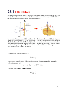
®
FIG. 3 Esempi - Examples
Perimetro = 5m - Cavo a 4 fili - Lunghezza spira = 20mt (5x4)
Perimeter = 5m - 4-wires cable - Coil lenght = 20m (5x4)
Périmètre = 5m - Fil à 4 conducteurs - Longueur spire = 20mt (5x4)
I
automatismi per cancelli
automatic entry systems
25014 CASTENEDOLO (BS)-ITALY
Via Matteotti, 162
Telefono ++39.030.2135811
Telefax ++39.030.21358279-21358278
http://www.ribind.it - email: [email protected]
F
AVVERTENZE
• Prima di dar inizio all’installazione leggere attentamente il presente fascicolo.
ln particolare, prendere visione dei dispositivi di sicurezza previsti dal prodotto per
utilizzarli con la massima efficacia.
• Il presente manuale si rivolge a persone abilitate all’installazione di “APPARECCHI
UTILIZZATORI Dl ENERGIA ELETTRICA” (ai sensi della legge N.46 del 5.3.1990) e
richiede una buona conoscenza della tecnica, esercitata in forma professionale.
Perimetro = 9m - Cavo a 3 fili - Lunghezza spira = 27mt (9x3)
Perimeter = 9m - 3-wires cable - Coil lenght = 27m (9x3)
Périmètre = 9m - Fil à 3 conducteurs - Longueur spire = 27mt (9x3)
GB
Perimetro = 13m - Cavo a 2 fili - Lunghezza spira = 26mt (13x2)
Perimeter = 13m - 2-wires cable - Coil lenght = 26m (13x2)
Périmètre = 13m - Fil à 2 conducteurs - Longueur spire = 26mt (13x2)
FIG. 4
INSTALLAZIONE TIPO
STANDARD INSTALLATION
INSTALLATION TYPE
SPIRA A 2 FILI
2-WIRE COIL
SPIRE À 2 CONDUCTEURS
FIG. 8
DESCRIZIONE
Il dispositivo è adatto al rilevamento di masse metalliche che si vengono a trovare nel
campo magnetico creato da un apposito circuito esterno (elemento sensibile) ad esso
connesso.
Il sistema si compone di 4 elementi:
1) Apparecchiatura di rilevamento con chiusura in materiale plastico (Fig.1).
2) Zoccolo per montaggio a pannello o su barra DIN46277 (Fig.10).
3) Elemento sensibile (non di nostra fornitura) dovrà essere realizzato con cavo
multipolare a due o più fili nei modi e nelle misure descritte (Fig.3).
4) Cavo bipolare per il collegamento (non di nostra fornitura) dalla spira al detector
(Fig.4).
FIG. 9
SPIRA A 3 FILI
3-WIRE COIL
SPIRE À 3 CONDUCTEURS
POSSIBILITÀ D’IMPIEGO
Il DETECTOR è un valido apparecchio di rilevazione da impiegare:
- Nell’apertura automatica di cancelli e portoni che delimitano passi carrai con intenso
movimento di automezzi in uscita (condomini, edifici pubblici e industriali).
- Nella rilevazione di autoveicoli su parcheggi regolamentati.
- In prossimità di impianti semaforici a funzionamento automatico.
- Per la rilevazione, su punti prestabiliti, di masse metalliche in genere.
N.B.: L’uso e l’installazione di questa apparecchiatura deve rispettare rigorosamente le
indicazioni fornite dal costruttore e le normative di sicurezza vigenti.
Cavo bipolare intrecciato
Bipolar interlaced cable
Cable bipolaire torsadé
Cavo bipolare intrecciato
Bipolar interlaced cable
Cable bipolaire torsadé
REALIZZAZIONE DELLA SPIRA (Fig.3)
La spira dovrà essere realizzata in base alle necessità d’impianto costituito
essenzialmente da un cavo multipolare composto da almeno due fili di Ø1÷1,5 mm.
I fili che compongono il cavo vanno collegati in serie fra loro; molto importante è che la
somma delle loro lunghezze non superi i 40 mt e non sia inferiore ai 20mt.
N.B.- Si consiglia di realizzare la spira con uno sviluppo di sagoma rettangolare avente
il lato corto di 50cm e la lunghezza del lato lungo conforme alle necessità d’impianto.
COLLEGAMENTI ALLO ZOCCOLO
SOCKET CONNECTIONS
CONNEXIONS A LE SOCLE
SENSORE ELETTRONICO
AUTOTARANTE A SPIRA
INDUTTIVA
cod.ACG9060
COLLEGAMENTO ALLO ZOCCOLO
1-2 Alimentazione 230V 50/60Hz
3-4 Uscita impulsiva contatto relé Comune/N.A. per automazioni RIB. La massa metallica
verrà rilevata solo per un tempo di 1 sec., trascorso il quale il relé si predispone ad
una nuova rilevazione.
5-6-10 Uscita continua contatto relé N.A/Comune/N.C. La massa metallica sarà rilevata
per tutto il tempo in cui persiste sulla spira.
7-8 Ingresso cavetto bipolare intrecciato di collegamento alla spira induttiva.
9 Ingresso del cavo di massa.
N.B.: Nella realizzazione della spira induttiva è importante utilizzare un unico cavo
con più poli 3x1mm2, 4x1mm2, 5x1mm2. Gli eventuali poli non utilizzati vanno
isolati e non collegati.
È bene isolare i punti di collegamento.
Il cavo interrato non deve subire spostamenti dal passaggio di automezzi.
TARATURA DEL SENSORE
Collegati i terminali della spira agli appositi morsetti (7-8), la regolazione del SENSORE
dovrà essere effettuata, in assenza di masse metalliche sulla spira, seguendo la
procedura indicata:
- Alimentare il Sensore collegando la tensione ai morsetti 1-2 e la terra al morsetto 9.
- Selezionare il Livello di Sensibilità (Fig.1):
DIP1 OFF DIP2 OFF basso
DIP1 ON DIP2 OFF medio basso -> consigliato per auto e camion
DIP1 OFF DIP2 ON
medio alto -> consigliato per auto e camion
DIP1 ON DIP2 ON
alto
-> consigliato per motocicli
- Il sensore è dotato di due relé, uno impulsivo (per cancelli automatici e barriere morsetti 3-4) ed uno a tempo (morsetti 6-10 N.C. e 6-5 N.O.).
- Se viene utilizzato il Relé a Tempo, selezionare il Tempo di tenuta:
DIP3 OFF 5 minuti
DIP3 ON continuo
- Selezionare il livello di Frequenza
Alto - DIP4 OFF / Basso - DIP4 ON
Si seleziona la Frequenza alta se l’induttanza L ha valore basso e viceversa.
- Premere il pulsante RESET.
Il dispositivo inizia la fase di autotaratura (LED VERDE lampeggiante).
Al termine l’apparecchiatura si stabilizza sul funzionamento ottimale (LED VERDE
acceso).
FIG. 10
CALCOLO DELLA SPIRA
La spira deve avere induttanza con valore compreso tra 100 e 300µH.
Per determinare il valore dell’induttanza ottenuta utilizzare la seguente formula:
FIG. 5
L = N2 x (P:0,61)
L=induttanza (compresa tra 100 e 300µH)
N=numero di spire
P=perimetro della spira (mt)
Es: Cancello largo 6mt. La spira avrà forma rettangolare con lato corto 0,5mt e lato lungo
6mt.
Il Perimetro P allora ha valore 13mt.
Se N=2 ottengo L=4x(13:0,61)=85µH
VALORE INSUFFICIENTE
Se N=3 ottengo L=9x(13:0,61)=192µH
VALORE CORRETTO
Se N=4 ottengo L=16x(13:0,61)=341µH
VALORE ECCESSIVO
FIG. 6
INTERRAMENTO SPIRA
EMBEDDING THE COIL
PLACEMENT SOUS TERR DE LA SPIRE
CVA1321 - 24062004 - rev03
FIG. 7
8 0 2 8 2 6 5 07 1 0 8 7 >
INSTALLAZIONE
- Ricavare nella zona che dovrà essere interessata dall’azione della spira, uno scavo di
sagoma rettangolare (per auto e camion fig.5) o a parallelogramma (per biciclette e
motocicli fig.6).
N.B.: Lo scavo non dovrà superare i 10cm di profondità (fig.7).
- Se necessario proteggere la spira con una speciale guaina in materiale plastico adatta
all’interramento.
- Posizionare la spira nello scavo accertandosi che assuma una posizione corretta,
distaccata almeno 50cm da tubi di scarico, idranti e canaline. Se si è in presenza di rete
metallica sottostante rialzare la spira di almeno 5cm.
- Collegare i due terminali della spira al sensore (fig.8-9)
- Il collegamento tra spira e sensore (sugli appositi morsetti 7-8) dovrà essere realizzato
con cavo bipolare intrecciato (da min 1mm2) per una distanza inferiore ai 200mt.
- Interrare la spira fissandola con del cemento in modo da farle assumere una posizione
stabile, che eviti qualsiasi possibilità di spostamento.
FUNZIONE LED
Se il sensore è in fase di Autotaratura il LED VERDE lampeggia.
Se il funzionamento è normale il LED VERDE è acceso.
Se un veicolo viene rilevato il LED ROSSO si accende.
Se la spira ha problemi il LED ROSSO lampeggia.
N.B.: La mancanza ed il ripristino dell’alimentazione fa eseguire al dispositivo un ciclo di
taratura in automatico.
CARATTERISTICHE TECNICHE
• Alimentazione: 230Vac 50/60Hz
• Potenza assorbita: 2,5 VA
• Temperatura ambiente ammessa: -20÷70°C
• Induttività spira: 25÷800µH, consigliati 100÷300µH
• Lunghezza cavetto bipolare intrecciato di collegamento alla spira: <200m
• Resistenza spira <20 Ω (compreso il cavo)
• 2 relé in uscita, di cui:
il primo, impulsivo, con contatto NA;
il secondo, di presenza, con contatto di scambio NA-NC
• Contatti: 2A, 125VA/60W (resistivi) - Per i carichi induttivi prevedere l’installazione di
filtri antidisturbo con funzione di eliminazione scintille.
FIG. 2
FIG. 1 SENSORE
Stato spira - LED ROSSO
Controllo spira - LED
VERDE
Sensibilità
Tempo di tenuta relé
Frequenza
I
T
A
L
I
A
N
O
®
E
N
G
L
I
S
H
automatismi per cancelli
automatic entry systems
25014 CASTENEDOLO (BS)-ITALY
Via Matteotti, 162
Telefono ++39.030.2135811
Telefax ++39.030.21358279-21358278
http://www.ribind.it - email: [email protected]
REMARKS
• Before commencing with the installation of this appliance make sure that you have read
the following instructions carefully.
In particular familiarise yourself with the safety devices required by the system, only then
will you be able to use them to great effect.
• These instructions are aimed at professionally qualified “installers of electrical
equipment” and must respect the local standards and regulations in force .
DESCRIPTION
This device is suitable for detecting the presence of metallic masses in a magnetic field
generated by a special external circuit (sensitive element) connected to it.
The system is made up of 4 parts:
1) An detection device contained in a special protective case made of extruded
aluminium with shockproof plastic end pieces (fig.1).
2) Socket for fitting on panelling or rails (fig.10).
3) A sensitive element (not supplied by us) that should be made up of a multipolar cable
with one or more wires and must respect the measurements as specified in the
drawings (fig.3).
4) A bipolar interlaced cable (not supplied by us) to connect the coil to the detector (fig.4).
USE
The DETECTOR is best used in the following fields:
- The automatic opening of gates and doors where there is intense traffic (for blocks of
flats, office buildings and industry etc.).
- The control of vehicles in pay car parks.
- Near automatic traffic light installations.
- Detection, in predetermined places, of the presence of metallic masses in general.
Note: The use and installation of these appliances must rigorously respect the
indications supplied by the manufacturer and the safety standards and regulations
in force.
MAKING THE COIL (FIG.3)
The coil shall be made by taking into consideration the systems requirements, the
fundamental part of which is a multipolar cable, made up of at least two wires (Ø1÷1,5
mm). The wires that make up the cable have to be connected in series. It is important
that the sum of their lengths does not exceed 40 m and is not less than 20 m.
N.B.: It is advisable to use a rectangular form when realising the coil, the shorter side
of which should measure 50 cm and the length will depend on the system
requirements.
COIL CALCULATION
The coil must have inductance with value between 100 and 300µH.
To determine the value of the obtained inductance use the following formula:
L = N2 x (P:0,61)
L=inductance (compresa tra 100 e 300µH)
N=number of coils
P=perimeter of coils (mt)
Example: Gate with width 6mt. The coils will have rectangular shape with short side 0,5
mt and long side mt 6.
So the Perimeter P is of mt 13.
If N=2 obtain L=4x(13:0,61)=85µH INSUFFICIENT VALUE
If N=3 obtain L=9x(13:0,61)=192µH CORRECT VALUE
If N=4 obtain L=16x(13:0,61)=341µH EXCESSIVE VALUE
INSTALLATION
- Dig a rectangular (for cars and trucks fig.5) or a parallelepiped (for bycicles or
motorcycles fig.6) shaped excavation in the area which is to be controlled by the coil.
N.B.: The excavation must not be deeper than 10 cm (fig.7).
- If necessary protect the sensitive element with a special plastic sheath which is suitable
for laying underground.
- Place the coil into the excavation making sure that it lies correctly, detached at least 50
cm from draining pipes, hydrants and electrical pipes. If there is metallic net below,
raise the coils of at least 5 cm.
- Connect the coil to the detector (fig.8-9)
- The connection between coil and detector (contacts 7-8) must be realized with a bipolar
interlaced cable (at least 1 mm2) for a distance under 200 mt.
- Lay the coil underground and embed it in cement to ensure a stable position and to
prevent it from moving.
SOCKET CONNECTION
1-2 Power supply 230Vac 50/60 Hz
3-4 Impulsive output, relay contact common/N.O.. The metallic mass will be monitored
SELF-ADJUSTING METALLIC
MASS DETECTOR
WITH AN INDUCTIVE COIL
cod.ACG9060
for 1 second time period after which the relay will reset and wait for the next positive
reading.
5-6-10 Continuos output, relay contact N.O./common/N.C. The metallic mass will be
monitored for the entire time in which it effects the coil.
7-8 Inductive coil bipolar interlaced cable in input.
9 Mass cable in input.
N.B.: When constructing the inductive coil a single cable with more than one pole
3x1mm2, 4x1mm2, 5x1mm2 must be used. Unusued poles should be
disconnected and isolated.
The serial connection points must be isolated.
The cable inlaid into the ground must not move when subject to passing vehicles.
ADJUSTING DETECTOR
The adjustment of the detector must be carried out after having connected the coil to the
clamps 7-8 and with no metallic masses in the vicinity as follows:
- Activate the sensor connecting the tension to the clamps 1-2 and the ground to the
clamp 9.
- Choose the sensibility level (fig.1):
DIP1 OFF DIP2 OFF low
DIP1 ON DIP2 OFF medium low -> advised for cars and trucks
DIP1 OFF DIP2 ON
medium high -> advised for cars and trucks
DIP1 ON DIP2 ON
high
-> advised for motorcycles
- The detector has 2 relays, one is impulsive (clamps 3-4) and one is timing (clamp 6-10
N.C. and 6-5 N.O.)
- If You use the timing relay, choose the activation time
DIP3 OFF 5 minutes
DIP3 ON continuous
- Choose the frequency level
High - DIP4 OFF / Low - DIP 4 ON
Choose the high frequency if inductance L has low value and vice versa
- Press the RESET button
The device begins the selfadjustment phase (GREEN LED flashes)
At the end the equipment stabilize itself on optimal function (GREEN LED is lighted)
LED FUNCTIONS
If the sensor is in selfadjustable phase the GREEN LED flashes.
If the function is normal the GREEN Led is lighted
If a vehicle has been noticed the RED LED turn on
If the coils has problems the RED LED flashes
N.B. If the power is turned off and then turned on again, the device will automatically
carry out a setting cycle.
TECHNICAL SPECIFICATION
• Power supply: 230Vac 50/60 Hz
• Absorbed power: 2,5Va
• Ambient temperature advised: -20÷70°C
• Coil inductance: 25÷800µH, advised 100÷300µH
• bipolar interlaced cable lenght:<200mt
• coil resistance: <20Ω (together with the cable)
• 2 relays in output of which:
the first, impulsive with NO contacts
the second, in presence, with exchange contact NO-NC
• Contacts: 2A, 125VA/60W (resistive) For inductive loads foreseen installation of noise
filter with spark elimination function
FIG. 2
FIG. 1 DETECTOR
Coil status - RED LED
Coil control - GREEN LED
Sensibility
Activation time
Frequency
®
automatismi per cancelli
automatic entry systems
25014 CASTENEDOLO (BS)-ITALY
Via Matteotti, 162
Telefono ++39.030.2135811
Telefax ++39.030.21358279-21358278
http://www.ribind.it - email:[email protected]
AVERTISSEMENT
• Avant de procéder à l’installation, lire attentivement ce livret.
En particulier, se familiariser avec les dispositifs de sécurité prévus sur le produit afin de
pouvoir les utiliser au mieux.
• Ce livret est destiné à des personnes titulaires d’un certificat d’aptitude professionnelle
pour l’installation des “APPAREILS ÉLECTRIQUES” et requiert une bonne
connaissance de la technique appliquée professionnellement.
DESCRIPTION
Le dispositif est apte à detecter des masses métalliques qui se trouvent dans le champ
magnétique créé par un circuit spécial externe (élément sensible) connecté à celui-ci.
Le système comporte 4 éléments:
1) Un appareil de relèvement assemblé dans un boîtier spécial de protection en fusion
d’aluminium avec fermeture en matière plastique (Fig.1).
2) Socle pour montage sur panneaux ou sur barre DIN46277 (fig.10)
3) Un élément sensible (pas fourni de notre part) qui devra être réalise avec un câble
multipolaire à deux ou plusieurs fils selon les instructions dimensions indiquées (fig.3).
4) Un câble bipolaire torsadé pour le branchement (pas fourni de notre part) de I’élément
sensible à l’appareil (fig.4).
POSSIBILITÉ D’EMPLOI
Le DETECTEUR est un appareil efficace pour la détection, pouvant être utilisé pour:
- ouverture automatique de portails et portes qui délimitent dés passages pour véhicules
avec trafic intense en sortie (immeuble, édifices publics et industriels)
- détection de véhicules sur parking réglementés;
- à proximité de feux de signalisation à fonctionnement automatique;
- détection de masses métalliques en général aux points préétablis.
N.B.: L’emploi et l’installation de cet appareil doivent respecter rigoureusement les
indications fournies par le constructeur et les normes de sécurité en vigueur.
RÉALISATION DE LA SPIRE (fig.3)
La spire devra être réalisé en fonction des exigences de l’installation, être constitué
essentiellement.d’un câble multipolaire et être composé au moins de deux fils d’un
diamètre (Ø1÷1,5 mm.).
Les fils qui constituent le câble devront être branchés en série entre eux;
il est très important que la somme de leur longueur ne dépasse pas 40 m et ne soit
pas inférieure à 20 m.
N.B.: il est conseillé de réaliser la spire de forme rectangulaire ayant le coté court de
50cm et la longueur du coté long conforme aux exigences de l’installation.
CALCUL DE LA BOUCLE
La boucle doit avoir une inductance comprise entre 100 et 300µH.
Pour determiner cette valeur appliquer la formule suivante:
L = N2 x (P:0,61)
L=inductance (comprise entre 100 et 300µH)
N=nombre de spires
P=périmétre de la boucle (mt)
Ex: Largeur portail 6mt. La boucle aura una forme rectangulaire de 0,5mt x 6mt.
Le Périmétre P est donc de 13mt.
Si N=2 on obtient L=4x(13:0,61)=85µH
VALEUR INSUFFISANTE
Si N=3 on obtient L=9x(13:0,61)=192µH
VALEUR CORRECTE
Si N=4 on obtient L=16x(13:0,61)=341µH
VALEUR EXCESSIVE
INSTALLATION
- Dans la zone qui doit être intéressée par l’action de la spire, pratiquer une cavité de
forme rectangulaire (pour voitures et camion fig.5) ou en parallelogramme (pour cycles
et motocycles fig.6).
N.B.: La cavité ne devra pas dépasser les 10 cm de profondeur (fig.7).
- Si nécessaire, protéger la spire au moyen d’une gaine en matériel plastique, indiquée
pour l’enfouissement.
- Positionner la boucle dans la rainure en prenant ben soin, en s’assurant d’etre distant
d’au moins 50cm de toute canalisations. Dans le cas de grille métallique s’éloigner d’au
moins 5cm.
- Le raccordement entre boucle et détecteur (bornes 7-8) devra être réaliser avec un
cable bipolaire torsadé (de section minimale 1mm2) d’une longueur inférieure à 200mt.
- Enterrer la spire en la fixant à l’aide de ciment, de façon à rendre sa position stable et
à lui éviter tout déplacement.
1-2
3-4
5-6-10
7-8
9
DETECTEUR ELECTRONIQUE
AUTOREGLANT
A SPIRE INDUCTIVE
cod.ACG9060
RACCORDEMENTS SUR LE SOCLE
Alimentation 230Vac 50/60Hz
Sortie contact impulsion N.O. (1 sec) pour automatismes RIB.
Sortie contact temporise 5min ou permanant
Entrée boucle.
Terre.
N.B.: Pour la réalisation de la boucle utiliser un cable multiconducteurs 3x1mm2,
4x1mm2, 5x1mm2. Les conducteurs eventuellement non utilisés devront être
isolés.
Bien isoler les connections enterrees sous peine de disfonctionnement.
La boucle ne doit pas pouvoir bouger sous l’action d’un passage de véhicule.
REGLAGE DU DETECTEUR
Raccorder les extrémites de la boucle sur les bornes dédiées (7-8), la réglage du
détecteur devra être effectué en l’absence de masse métallique sur la boucle, puis suivre
la procédure suivante:
- Alimenter le détecteur sur les bornes 1 et 2 et raccorder la terre à la borne 9.
- Selectionner le niveau de sensibilité (fig.1):
DIP1 OFF DIP2 OFF basse
DIP1 ON DIP2 OFF mi-basse
-> conseillé pour auto et camion
DIP1 OFF DIP2 ON
mi-haute
-> conseillé pour auto et camion
DIP1 ON DIP2 ON
haute
-> conseillé pour motocycles
- Le détecteur est muni de deux relais, un impulsionnel (bornes 3-4) pour automatismes
RIB et un temporisé (bornes 10 N.F., 5 N.O. et 6 common).
- Selection du temps d’excitation du relais temporisé:
DIP3 OFF 5 minutes
DIP3 ON permanant
- Sélectionner le niveau de frequence
Haute - DIP4 OFF / Basse - DIP4 ON
Sélectionner une fréquence haute si l’inductance est basse et viceversa.
- Appuyer sur le bouton RESET.
L’appareil commence le réglage automatique et la LED VERTE clignote.
Celle ci restera allumée a la fin de la procédure.
SIGNALISATION LED
LED VERTE clignotante = Phase de réglage auto
LED VERTE allumée = Fonctionnement normal
LED ROUGE allumée = Véhicule détecté
LED ROUGE clignotante = Defaut boucle
N.B.: Á la mise sous tension ou aprés une coupure de courant l’appareil effectue un
réglage automatique.
CARACTERISTIQUES TECHNIQUES
• Alimentation: 230Vac 50/60Hz
• Puissance absorbée: 2,5VA
• Temperature de fonctionnement: -20÷70°C
• Inductance boucle: 25÷800µH, conseillée 100÷300µH
• Longueur maxi boucle/detecteur : <200m
• Resistance boucle <20 Ω (liaison comprise)
• 2 relais de sortie:
1 à impulsion (contact N.O.);
Un autre en presence (contact inverseur)
• Intensité contact: 2A, 125VA/60W - Dans le cas de charge inductive installer un filtre
pour absorber les arcs électriques.
FIG. 2
FIG. 1 DETECTEUR
Etat boucle - LED ROUGE
Controle boucle - LED VERTE
Sensibilité
Tempo relais
Frequence
F
R
A
N
Ç
A
I
S
E
Scaricare