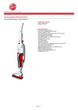
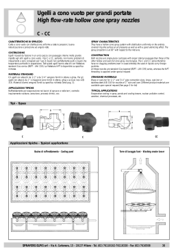
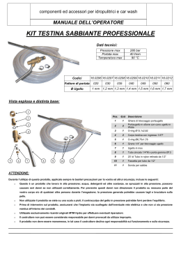
co mfo rt | n ozz les
Supply air nozzle
GD
Dimensions
1
50
15˚
3
Ø 77
Ø 70
Hole min. Ø70
2
4
5
Description
GD is a rubber supply air nozzle suitable for ventilation of
large areas where long throws are required. The nozzle can
be adjusted for directional airflow, and can be installed
directly into circular ducts, ( min. Ø250 mm ), or duct walls,
( min. height = 100 mm ). The nozzle can be used for both
heated and cooled air.
Free area: 0.0027 m2
Straight groove: for rectangular duct.
Oblique groove: for circular duct.
6
Mounted in duct
7
Ø
8
• Directional airflow
• Long throws
• Simple installation
9
Maintenance
10
The visible parts of the nozzle can be wiped with a damp
cloth.
11
Ø > 250
12
13
H
14
15
16
H > 100
17
Ordering example
Product
Type
GD
Materials and finish
Nozzle: EPDM rubber, hardness 60, black
We reserve the right to make changes without prior notice
18
415
co mfo rt | n ozz les
Supply air nozzle
GD
Technical data
1
2
Supply air
Capacity
Volume flow q[l/s] and [m3/h], total pressure pt[Pa], throw l0.3
and sound level LWA [dB(A)] can be seen in the diagrams.
'$
'$
Throw l0.3
3
L ;M=
Throw l0.3 can be seen in the diagrams for isothermal air at a
terminal velocity of 0.3 m/s.
4
5
Resulting sound effect level
The sound effect level from the nozzles must be added logarithmically to the sound effect level from the flow noise in the
duct. See sample calculation, section Nozzle calculations.
L;M=
Q6 ;LS =
Q6 ;MH=
Frequency-related sound effect level
6
The sound effect level in the frequency band is defined as
Lwok = LWA+ Kok. Kok values can be seen in the table below.
ǻpt [Pa] GD
500
400
50
300
7
Table
200
40
150
35
100
Centre frequency Hz
8
45
Size
63
125
250
500
1K
2K
4K
8K
GD
9
-2
0
1
-6
-14
-21
-25
30
70
25
50
20
30
20
9
15
LWA dB(A)
10
qV [l/s]
10
15
20
30
40
50
60
70
80
qV [m3/h]
10
40
50
60
70
11
12
13
14
15
16
17
18
416
We reserve the right to make changes without prior notice
80
100
150
200
co mfo rt | n ozz les
Supply air nozzle
Calculation
Resulting sound effect level
To calculate the resulting sound effect level from the nozzles, add the sound effect level from the nozzles (LWA nozzle)
and the sound effect level from the flow noise in the duct
(LWA duct) logarithmically.
Diagram 1, sound effect duct, LWA duct.
,7!D"!
Extension of throw for two nozzles, positioned side by
side:
1
If two nozzles are positioned next to each other, the air jets
will be amplified, thereby extending the throw. To calculate
this, use the diagram below, in which the distance between
the nozzles is designated D. The calculation factor K4 must
be multiplied by the throw l03. The throw is not extended further with more nozzles.
2
3
4
+
5
,7!D"!
6
Q6;LS=
Q6;MH=
7
+
Diagram 2, addition of sound levels.
Difference to be added to the highest dB value (dB)
$;M=
L;M=
3
8
Sample calculation:
LAD-125. Distance D = 1.5 metres.
Volume of air:
q = 15 l/s
2
Diagram throw under selected nozzle
Specified throw:
l0.3 = 7 m
D [m] / l0.3[m]
1.5 / 7 = 0.21
1
0
0
2
4
6
Difference between the dB values (dB)
8
10
12
K4 calculation factor
Can be seen in the diagram
Resulting throw
K4 x l0.3 = 1.25 x 7 m = 8.75 m
LW Duct
v Duct
K4 = 1.25
9
10
11
12
LW Nozzle
v Nozzle
Sample calculation:
LAD-200
ΔPt nozzle
13
q = 100 l/s
90 Pa
Duct size:
In order to achieve a sensible distribution of the air out to the
nozzles without using a damper, it is recommended that the
pressure loss in the nozzle be 3 times higher than the
dynamic pressure in the duct system.
Selected duct dimension
Ø 400
Number of nozzles at joint
6
Volume of air in the duct
6 x 100 = 600 l/s
43 dB(A)
LWA duct (can be seen in diagram 1)
LWA nozzle (can be seen in product diagram) 37 dB(A)
Difference between db values
6 dB(A)
Value to be added to the highest dB value
(diagram 2)
1 dB(A)
Resulting sound effect level: 43 +1 =
44 dB(A)
We reserve the right to make changes without prior notice
14
15
16
17
18
417
co mfo rt | n ozz les
Supply air nozzle
Calculation
Sample calculation: Heated air
Supply air with cooled air
1
LAD-200:
X
Final velocity
Y
H
2
α
3
X = K1 ×
q
= 0,020 × 400 = 27 m
0,3
vx
Y = K2 ×
273
X3
× Δt = 24 ×
× 6 = 17,7 m
4002
q2
H = X × sin α = 27 × 0,87 = 23,4 m
L = X × cos α = 27 × 0,5 = 13,5 m
L
4
Supply air with heated air
5
α
H
6
X
Y
7
L
8
L
cos α
X=
9
H
sin α
=
H = L × tan α
Terminal velocity VX:
10
11
vx = K1 ×
13
14
15
16
q
X
Deflection Y:
3
Y = K2 × X2 × Δt
q
12
Sample calculation: Cooled air
LAD-200:
Final velocity
Fan
q = 400 m3/h
Δt = -6K α = 30°
vx = 0,3 m/s
q
X
q
X = K1 ×
= 0,020 × 400 = 27 m
0,3
vx
vx = K1 ×
Y = K2 ×
X3
273 × 6 = 17,7 m
× Δt = 24 ×
q2
4002
H = X × sin α = 27 × 0,5 = 13,5 m
L = X × cos α = 27 × 0,87 = 23,4 m
17
18
418
q = 400 m3/h
Δt = -6K α = 60°
vx = 0,3 m/s
We reserve the right to make changes without prior notice
co mfo rt | n ozz les
Supply air nozzle
Calculation
Calculation factors:
1
Free
area
Size
K2
K1
K3
A m2
m3/h
l/s
m3/h
l/s
m3/h
l/s
0.0029
0.0071
0.0095
0.0165
0.0254
0.0398
0.037
0.023
0.020
0.0153
0.0122
0.0097
0.133
0.083
0.072
0.055
0.044
0.035
3.9
15.6
24.0
54.4
104
206
0.30
1.20
1.85
4.2
8.0
15.9
0.24
0.122
0.097
0.064
0.046
0.033
0.86
0.44
0.35
0.230
0.166
0.119
0.0056
0.0095
0.0154
0.0240
0.026
0.020
0.0157
0.0127
0.094
0.072
0.057
0.046
10.7
24.0
49.0
96.0
0.83
1.85
3.78
7.41
0.145
0.097
0.068
0.048
0.52
0.35
0.24
0.17
0.0027
0.038
0.137
3.5
0.27
0.26
0.92
0.0200
0.0310
0.0490
0.0780
0.0090
0.0073
0.0058
0.0046
0.032
0.026
0.021
0.017
114
219
435
875
8.8
16.9
34
68
0.048
0.034
0.024
0.017
0.173
0.122
0.086
0.062
2
LAD
125
160
200
250
315
400
3
DAD
160
200
250
315
4
5
GD
GTI-1
200
250
315
400
6
7
Vertical supply air with heated air
8
9
Ym
10
11
Y m = K3 x
q
√ Δt
(m)
12
Sample calculation:
LAD-160
q = 200 m3/h
Δt = 10 K
13
The distance to the turning point of the air jet:
Ym = K3 x
q
√ Δt
14
(m)
Ym = 0,122 x 200 (m)
√ 10
Ym = 7,7 m
15
16
17
18
We reserve the right to make changes without prior notice
419
co mfo rt | n ozz les
Nozzle diffuser
GTI
Dimensions
1
Installation 0
Ød1
2
3
4
E
5
Diffused supply air – for installation in a circular duct or fitting. Supplied adapted to this form of installation as standard.
6
Installation 1
Description
GTI is a flexible supply air nozzle that is suitable for ventilation of large areas. The nozzle can be used for both heated
and cooled air and can be adjusted from diffused to concentrated supply air patterns. The supply air pattern can be
adjusted by turning the insert in relation to the central line of
the nozzle. The nozzle is equipped with Lindab Safe and can
be installed directly into a circular duct, fitting, wall or duct
side.
Ød1
7
8
9
• Flexible nozzle for cooling and heating
• Adjustable dispersal pattern
• Simple installation
E
Concentrated supply air – for installation in a circular duct or
fitting. The insert is turned 180 degrees.
Maintenance
The visible parts of the diffuser can be wiped with a damp
cloth.
10
11
Installation 2
12
ØA
Steel
Galvanised steel
Powder-coated
RAL 9010, gloss 30
F
Insert:
Connection:
Standard finish:
Standard colour:
Ød2
Materials and finish
13
14
The diffuser is available in other colours. Please contact
Lindab’s sales department for further information.
C
B
10
Diffused supply air – for installation in a wall or duct side.
Remove the external pipe.
Ordering example
Product
Type
Size
Version
GTI
bbb
A
Size
ØA
mm
B
mm
C
mm
Ød1
mm
E
mm
F
mm
Ød2
mm
Weight
kg
200
203
40
55
198
109
170
158
0,8
250
253
50
75
248
139
210
198
1,3
315
318
60
95
313
169
260
248
2,0
400
403
70
115
398
199
321
313
2,8
Free area for GTI nozzle – see pages Nozzle calculations.
We reserve the right to make changes without prior notice
15
16
17
18
409
co mfo rt | n ozz les
Nozzle diffuser
GTI
Technical data
1
2
Diffuse supply
Capacity
Volume flow q [l/s] and [m3/h], total pressure pt[Pa], throw
l0.3 and sound level LWA [dB(A)] can be seen in the diagrams.
Throw l0.3
3
Throw l0.3 can be seen in the diagrams for isothermal air at a
terminal velocity of 0.3 m/s
4
Resulting sound effect level
5
The sound effect level from the nozzles must be added logarithmically to the sound effect level from the flow noise in the
duct. See sample calculation, pages Nozzle calculations.
Frequency-related sound effect level
6
7
315
The sound effect level in the frequency band is defined as
Lwok = LWA+ Kok. Kok values can be seen in the table below.
Table 1 - diffused supply air
Centre frequency Hz
8
9
10
Size
63
125
250
500
1K
2K
4K
8K
200
250
315
400
15
13
16
14
0
-3
-1
-1
-5
-6
-6
-3
-6
-6
-2
0
-2
-1
-3
-5
-10
-14
-15
-16
-22
-14
-26
-27
-32
-33
-35
-32
Table 2 - concentrated supply air
Concentrated supply
Centre frequency Hz
11
Size
63
125
250
500
1K
2K
4K
8K
200
250
315
400
14
16
18
15
0
-3
-1
-4
-3
-6
-5
-6
-4
-4
-2
-4
-2
-2
-3
-2
-13
-16
-16
-21
-27
-25
-29
-34
-37
-28
-40
-38
12
15
Diffuse
bh
14
Air jet width bh
bh = 0,5 × l0,3
Concentrated
bh
13
bh = 0,2 × l0,3
16
17
18
410
We reserve the right to make changes without prior notice
co mfo rt | n ozz les
Supply air nozzle
Calculation
Resulting sound effect level
To calculate the resulting sound effect level from the nozzles, add the sound effect level from the nozzles (LWA nozzle)
and the sound effect level from the flow noise in the duct
(LWA duct) logarithmically.
Diagram 1, sound effect duct, LWA duct.
,7!D"!
Extension of throw for two nozzles, positioned side by
side:
1
If two nozzles are positioned next to each other, the air jets
will be amplified, thereby extending the throw. To calculate
this, use the diagram below, in which the distance between
the nozzles is designated D. The calculation factor K4 must
be multiplied by the throw l03. The throw is not extended further with more nozzles.
2
3
4
+
5
,7!D"!
6
Q6;LS=
Q6;MH=
7
+
Diagram 2, addition of sound levels.
Difference to be added to the highest dB value (dB)
$;M=
L;M=
3
8
Sample calculation:
LAD-125. Distance D = 1.5 metres.
Volume of air:
q = 15 l/s
2
Diagram throw under selected nozzle
Specified throw:
l0.3 = 7 m
D [m] / l0.3[m]
1.5 / 7 = 0.21
1
0
0
2
4
6
Difference between the dB values (dB)
8
10
12
K4 calculation factor
Can be seen in the diagram
Resulting throw
K4 x l0.3 = 1.25 x 7 m = 8.75 m
LW Duct
v Duct
K4 = 1.25
9
10
11
12
LW Nozzle
v Nozzle
Sample calculation:
LAD-200
ΔPt nozzle
13
q = 100 l/s
90 Pa
Duct size:
In order to achieve a sensible distribution of the air out to the
nozzles without using a damper, it is recommended that the
pressure loss in the nozzle be 3 times higher than the
dynamic pressure in the duct system.
Selected duct dimension
Ø 400
Number of nozzles at joint
6
Volume of air in the duct
6 x 100 = 600 l/s
43 dB(A)
LWA duct (can be seen in diagram 1)
LWA nozzle (can be seen in product diagram) 37 dB(A)
Difference between db values
6 dB(A)
Value to be added to the highest dB value
(diagram 2)
1 dB(A)
Resulting sound effect level: 43 +1 =
44 dB(A)
We reserve the right to make changes without prior notice
14
15
16
17
18
417
co mfo rt | n ozz les
Supply air nozzle
Calculation
Sample calculation: Heated air
Supply air with cooled air
1
LAD-200:
X
Final velocity
Y
H
2
α
3
X = K1 ×
q
= 0,020 × 400 = 27 m
0,3
vx
Y = K2 ×
273
X3
× Δt = 24 ×
× 6 = 17,7 m
4002
q2
H = X × sin α = 27 × 0,87 = 23,4 m
L = X × cos α = 27 × 0,5 = 13,5 m
L
4
Supply air with heated air
5
α
H
6
X
Y
7
L
8
L
cos α
X=
9
H
sin α
=
H = L × tan α
Terminal velocity VX:
10
11
vx = K1 ×
13
14
15
16
q
X
Deflection Y:
3
Y = K2 × X2 × Δt
q
12
Sample calculation: Cooled air
LAD-200:
Final velocity
Fan
q = 400 m3/h
Δt = -6K α = 30°
vx = 0,3 m/s
q
X
q
X = K1 ×
= 0,020 × 400 = 27 m
0,3
vx
vx = K1 ×
Y = K2 ×
X3
273 × 6 = 17,7 m
× Δt = 24 ×
q2
4002
H = X × sin α = 27 × 0,5 = 13,5 m
L = X × cos α = 27 × 0,87 = 23,4 m
17
18
418
q = 400 m3/h
Δt = -6K α = 60°
vx = 0,3 m/s
We reserve the right to make changes without prior notice
co mfo rt | n ozz les
Supply air nozzle
Calculation
Calculation factors:
1
Free
area
Size
K2
K1
K3
A m2
m3/h
l/s
m3/h
l/s
m3/h
l/s
0.0029
0.0071
0.0095
0.0165
0.0254
0.0398
0.037
0.023
0.020
0.0153
0.0122
0.0097
0.133
0.083
0.072
0.055
0.044
0.035
3.9
15.6
24.0
54.4
104
206
0.30
1.20
1.85
4.2
8.0
15.9
0.24
0.122
0.097
0.064
0.046
0.033
0.86
0.44
0.35
0.230
0.166
0.119
0.0056
0.0095
0.0154
0.0240
0.026
0.020
0.0157
0.0127
0.094
0.072
0.057
0.046
10.7
24.0
49.0
96.0
0.83
1.85
3.78
7.41
0.145
0.097
0.068
0.048
0.52
0.35
0.24
0.17
0.0027
0.038
0.137
3.5
0.27
0.26
0.92
0.0200
0.0310
0.0490
0.0780
0.0090
0.0073
0.0058
0.0046
0.032
0.026
0.021
0.017
114
219
435
875
8.8
16.9
34
68
0.048
0.034
0.024
0.017
0.173
0.122
0.086
0.062
2
LAD
125
160
200
250
315
400
3
DAD
160
200
250
315
4
5
GD
GTI-1
200
250
315
400
6
7
Vertical supply air with heated air
8
9
Ym
10
11
Y m = K3 x
q
√ Δt
(m)
12
Sample calculation:
LAD-160
q = 200 m3/h
Δt = 10 K
13
The distance to the turning point of the air jet:
Ym = K3 x
q
√ Δt
14
(m)
Ym = 0,122 x 200 (m)
√ 10
Ym = 7,7 m
15
16
17
18
We reserve the right to make changes without prior notice
419
l i nda b | di ff u sor i
Ugelli a lancio profondo
DAG
Dimensioni
1
DAG 100 - AK: 0.0022 mq
2
3
4
5
6
7
DAG 160 - AK: 0.0054 mq
Descrizione
8
Materiale e finitura
9
Ugello sferico per lanci profondi regolabile manualmente
in ogni direzione con angolo di 30°.
Materiale: Alluminio
Finitura:
satinato naturale con primer trasparente
10
Fissaggio
11
Mediante viti frontali direttamente su canale o con
raccordo per canale circolare.
12
Opzioni
Esecuzione verniciata
Esecuzione motorizzata, mod. DAG-1
13
DAG 300 - AK: 0.0179 mq
14
15
16
Esempio di ordinazione
17
DAG 430
Tipo
18
Soggetto a modifiche senza obbligo di preavviso
1
lin d ab | diff us o r i
Ugelli a lancio profondo
1
Dimensioni
DAG 400 - AK: 0.0308 mq
2
3
4
5
6
7
8
DAG 430- AK: 0.0401 mq
9
10
11
12
13
14
15
16
17
18
2
Soggetto a modifiche senza obbligo di preavviso
DAG
l i nda b | di ff u sor i
Ugelli a lancio profondo
DAG
Tabella di selezione
Velocità terminale Vt = 0, 37 m/s
1
DAG 100
2
Rumorosità
NR
<20
<20
<20
<20
25
30
35
40
3
50
Chiese, biblioteche
4
Ospedali
Appartamenti, uffici
Fabbricati commerciali
5
Altezza di installazione
Min
Max
2.0
2.7
2.1
2.8
2.2
2.9
2.3
3.0
2.4
3.1
Velocità di uscita Vk
m/s
2
4
6
8
10
12
Pa
3
13
31
57
91
Perdita di carico
Portata
m /h
16
32
48
64
81
Lancio
m
2.4
4.7
7.1
9.4
11.8
3
2,5
3.2
2.6
3.2
2.7
3.8
3.0
4.4
14
16
20
134
185
244
389
97
113
129
161
14.2
16.5
18.9
23.6
6
7
8
9
10
DAG 160
Rumorosità
NR
<20
<20
20
25
30
35
40
45
11
55
Chiese, biblioteche
12
Ospedali
Appartamenti, uffici
13
Fabbricati commerciali
Altezza di installazione
Min
Max
2.4
3.2
2.5
3.5
2.6
3.8
2.7
3.8
2.8
4
Velocità di uscita Vk
m/s
2
4
6
8
10
12
Pa
3
11
25
47
74
Portata
m /h
39
78
118
157
Lancio
m
3.6
7.2
10.8
14.4
Perdita di carico
3
2,9
4.1
3
4.2
3.2
4.4
3.6
4.8
14
16
20
108
150
198
315
196
235
274
314
392
18
21.6
25.2
28.8
36
14
15
16
17
18
Soggetto a modifiche senza obbligo di preavviso
3
lin d ab | diff us o r i
Ugelli a lancio profondo
Tabella di selezione
1
Velocità terminale Vt = 0, 37 m/s
2
DAG 300
3
DAG
Rumorosità
NR
<20
20
25
30
35
40
45
50
>55
Altezza di installazione
Min
Max
2.6
5.2
2.7
5.4
2.8
5.6
3
5.8
3.2
6
3.4
6.2
3.6
6.4
3.8
6.6
4.2
7
Velocità di uscita Vk
m/s
2
4
6
8
10
12
14
16
20
Pa
2
8
19
35
56
82
113
149
238
Chiese, biblioteche
4
Ospedali
Appartamenti, uffici
5
6
7
Fabbricati commerciali
Perdita di carico
Portata
m /h
129
257
386
514
643
771
900
1029
1286
Lancio
m
4.3
8.5
12.8
17
21.3
25.5
29.8
34
42.5
NR
<20
20
25
30
35
40
45
50
>55
Altezza di installazione
Min
Max
3.4
6.6
3.6
7.7
3.8
8.7
4
9.4
4.2
10
4.4
10.5
4.6
11
4.8
11.5
5.2
11.5
Velocità di uscita Vk
m/s
2
4
6
8
10
12
14
16
20
Pa
2
7
17
31
49
72
99
131
210
3
8
9
10
11
12
13
14
15
16
DAG 400
Rumorosità
Chiese, biblioteche
Ospedali
Appartamenti, uffici
Fabbricati commerciali
Perdita di carico
Portata
m /h
221
443
664
886
1107
1329
1550
1772
2214
Lancio
m
4.3
8.6
13
13.6
17.3
26
30.2
34.6
43.2
3
17
18
4
Soggetto a modifiche senza obbligo di preavviso
l i nda b | di ff u sor i
Ugelli a lancio profondo
DAG
Tabella di selezione
Velocità terminale Vt = 0, 37 m/s
1
DAG 430
2
Rumorosità
NR
<20
20
25
30
35
40
45
50
3
>55
Chiese, biblioteche
4
Ospedali
Appartamenti, uffici
Fabbricati commerciali
5
Altezza di installazione
Min
Max
3.4
6.6
3.6
7.7
3.8
8.7
4
9.4
4.2
10
Velocità di uscita Vk
m/s
2
4
6
8
10
12
Pa
2
7
16
29
46
Perdita di carico
4.4
10.5
4.6
11
4.8
11.5
5.2
11.5
14
16
20
68
93
123
197
Portata
m /h
288
577
865
1154
1442
1730
2019
2307
2884
Lancio
m
4.6
9.1
13.7
18.2
22.8
27.4
31.9
36.5
45.6
3
6
7
8
9
10
11
12
13
14
15
16
17
18
Soggetto a modifiche senza obbligo di preavviso
5
l i nda b | di ff u sor i
Ugelli sferico regolabile DAG-1
con attuatore termostatico
Dimensioni
1
DAG-1 300 - AK: 0.0179 mq
2
ATTUATORE
TERMOSTATICO
RAFFREDDAMENTO
COLD AIR
4
Ø298
Ø150
3
5
RISCALDAMENTO
WARM AIR
6
285
Descrizione
Diffusore orientabile in ogni direzione con un’inclinazione
massima di ±30°, la regolazione è automatica, senza
l’ausilio di alimentazione elettrica, mediante un attuatore
termostatico costituito da speciali materiali a memoria di
forma in Nichel-Titanio. Quando l’aria immessa è calda
(condizione di riscaldamento) l’attuatore sposterà il
flusso verso il basso, viceversa quando l’aria immessa
è fredda (condizione di raffreddamento) sposterà il
flusso verso l’alto, in accordo con l’angolo di deflessione
precedentemente calcolato. Il DAG-1 ha il vantaggio
di non richiedere nessuna preregolazione iniziale. Può
essere montato a canale, parete o plenum e infine
regolato. La regolazione dell’angolo di deflessione è
molto semplice e intuitiva mediante battute di arresto
meccaniche coadiuvate da una scala graduata colorata
posta all’interno del raccordo (foto1). Il diffusore lavora
in un range di temperatura tra i 15°C e i 40°C,alla
temperatura media di 25°C ha un angolo di deflessione
di 0°.
DAG-1 400 - AK: 0.0308 mq
Materiale e finitura
DAG-1 430 - AK: 0.0401 mq
ATTUATORE
TERMOSTATICO
8
20
RAFFREDDAMENTO
COLD AIR
10
30°
Ø398
Ø200
30°
9
11
RISCALDAMENTO
WARM AIR
12
Ø290
13
ATTUATORE
TERMOSTATICO
14
20
RAFFREDDAMENTO
COLD AIR
15
DAG-1 430
17
30°
Esempio di ordinazione
16
Ø398
Ø230
30°
Materiale: Alluminio
Finitura Standard: Satinato naturale con primer
trasparente
Installazione: Fissaggio mediante viti
7
RISCALDAMENTO
WARM AIR
18
Tipo
Ø290
Soggetto a modifiche senza obbligo di preavviso
1
lin d ab | diff us o r i
Ugelli sferico regolabile DAG-1
con attuatore termostatico
1
2
3
Tabella di selezione
Velocità terminale Vt = 0, 37 m/s
DAG-1 300
Rumorosità
NR
<20
20
25
30
35
40
45
50
>55
Altezza di installazione
Min
Max
2.6
5.2
2.7
5.4
2.8
5.6
3
5.8
3.2
6
3.4
6.2
3.6
6.4
3.8
6.6
4.2
7
Velocità di uscita Vk
m/s
2
4
6
8
10
12
14
16
20
Pa
2
8
19
35
56
82
113
149
238
Chiese, biblioteche
4
Ospedali
Appartamenti, uffici
5
6
7
Fabbricati commerciali
Perdita di carico
Portata
m /h
129
257
386
514
643
771
900
1029
1286
Lancio
m
4.3
8.5
12.8
17
21.3
25.5
29.8
34
42.5
NR
<20
20
25
30
35
40
45
50
>55
Altezza di installazione
Min
Max
3.4
6.6
3.6
7.7
3.8
8.7
4
9.4
4.2
10
4.4
10.5
4.6
11
4.8
11.5
5.2
11.5
Velocità di uscita Vk
m/s
2
4
6
8
10
12
14
16
20
Pa
2
7
17
31
49
72
99
131
210
3
8
9
10
11
12
13
14
15
16
DAG-1 400
Rumorosità
Chiese, biblioteche
Ospedali
Appartamenti, uffici
Fabbricati commerciali
Perdita di carico
Portata
m /h
221
443
664
886
1107
1329
1550
1772
2214
Lancio
m
4.3
8.6
13
13.6
17.3
26
30.2
34.6
43.2
3
17
18
2
Soggetto a modifiche senza obbligo di preavviso
l i nda b | di ff u sor i
Ugelli sferico regolabile DAG-1
con attuatore termostatico
Tabella di selezione
1
Velocità terminale Vt = 0, 37 m/s
2
DAG-1 430
Rumorosità
NR
<20
20
25
30
35
40
45
50
3
>55
Chiese, biblioteche
4
Ospedali
Appartamenti, uffici
Fabbricati commerciali
5
Altezza di installazione
Min
Max
3.4
6.6
3.6
7.7
3.8
8.7
4
9.4
4.2
10
4.4
10.5
4.6
11
4.8
11.5
5.2
11.5
Velocità di uscita Vk
m/s
2
4
6
8
10
12
14
16
20
Pa
2
7
16
29
46
68
93
123
197
Perdita di carico
Portata
m /h
288
577
865
1154
1442
1730
2019
2307
2884
Lancio
m
4.6
9.1
13.7
18.2
22.8
27.4
31.9
36.5
45.6
3
6
7
8
9
10
11
12
13
14
15
16
17
18
Soggetto a modifiche senza obbligo di preavviso
3
Scaricare