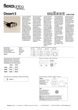
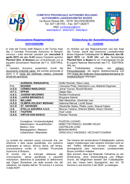
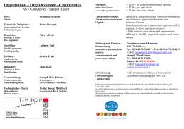
Italiano
English
Deutsch
Français
Il libretto istruzioni è parte integrante del prodotto. - The instruction booklet is an integral part of the product. - Die Anleitung ist Bestandtel des Produktes - Le manuel fait partie intégrante du produit.
Kit raccordi canalizzazione IP
IP ductwork connector kit
Anschluß-Kit zur Luftverteilung für IP
Kit raccords de gainage pour IP
ISTRUZIONI PER L’INSTALLATORE
INSTRUCTIONS FOR THE INSTALLER
AUFBAUANLEITUNG FÜR DEN INSTALLATEUR
INSTRUCTIONS POUR L’INSTALLATEUR
H07025440 / DT2000680-01
Italiano
INSTALLAZIONE
DT2012234-00
Con l’inserto a pellet è possibile , installando uno dei due raccordi opzionali ( per collegamento posteriore
o inferiore ), prelevare l’uscita dell’aria calda e canalizzarla in altri ambienti con tubi flessibili diametro 55.
Solo il ventilatore sinistro è predisposto per la canalizzazione.
Per la movimentazione in sicurezza del prodotto e prima di procedere a qualsiasi operazione di installazione,
leggere attentamente le seguenti istruzioni ed il libretto istruzioni del prodotto.
Prima di procedere all’installazione dell’inserto provvedere ad effettuare la canalizzazione ed arrivare con
il tubo flessibile nella zona posteriore sinistra di installazione del prodotto.
I kit raccordi canalizzazione sono progettati con un innesto scorrevole per consentire l’estrazione
dell’inserto a pellet per gli interventi di manutenzione o carico pellet.
Per indicazioni sull’uso e canalizzazione del sistema Multifuoco fate riferimento al libretto istruzioni fornito
con il prodotto.
- Estrarre il monoblocco dalle guide scorrevoli e
togliere dal lato sinistro del monoblocco il condotto
inferiore ( A ) svitando le 3 viti di fissaggio ( B )
e sostituirlo con l’adattatore (C) orientato verso la
parte posteriore [Fig.1]
Fig. 1
B
C
A
DT2033191-00
DT2033191-0
2
H07025440 / DT2000680-01
Non rimuovere la staffa di fissaggio del
tubo scarico fumi ( H ) ne allentare le viti.
[Fig.2]
Fig. 2
F
E
E
Italiano
- Visti gli spazi ridotti , per svitare le viti ( B ) può
essere necessario rimuovere il ventilatore ( D ) e
la paratia ( F ).
In tal caso togliere il ventilatore ( D ) con la relativa
flangia di fissaggio svitandone le 3 viti e rondelle
( E ) mentre per la paratia ( F ) svitare le viti ( G ).
D
E
G
H
A
DT2033192-0
DT2033192-00
- Dopo aver effettuato la canalizzazione,
posizionare e fissare il basamento dell’inserto a
pellet, quindi collegare con l’ausilio delle fascette
(O) il tubo flessibile all’uscita del raccordo
posteriore (I) o inferiore ( L ) e tramite le viti (M)
fissare questi ultimi al blocco scarico fumi (N)
[Fig.3].
Fig. 3
O
M
I
- Proseguire poi con l’installazione dell’inserto
come descritto nel relativo libretto istruzioni.
N
M
N
L
O
DT2033194-0
DT2033194-00
H07025440 / DT2000680-01
3
INSTALLATION
DT2012234-00
By installing one of the two optional connectors (for rear or bottom connection), the hot air flowing out of
the pellet-burning fireplace insert can be ducted to other rooms using hoses with diameter 55.
English
Only the fan on the left side is set up for ducting.
To handle the appliance in all safety, before carrying out any installation work carefully read the following
instructions and the instruction booklet accompanying the appliance.
Before installing the fireplace insert, lay the ductwork so that the hose arrives at the rear left installation
area of the appliance.
The ductwork connector kits are designed with a sliding coupling so that the pellet fireplace insert can be
pulled out for maintenance or pellet loading.
For instructions on how to use and duct the Multifuoco system, refer to the instruction booklet
accompanying the appliance.
Remove the insert from the guides and remove the
lower pipe ( A ) from the insert having removed
the 3 fastening screws ( B ); replace the lower
pipe with the adapter (C) with outlet facing to the
rear. [Fig.1]
Fig. 1
B
C
A
DT2033191-00
DT2033191-0
4
H07025440 / DT2000680-01
Do not remove the flue gas outlet pipe
fastening bracket ( H ) or loosen the
screws. [Fig.2]
Fig. 2
F
E
E
D
E
English
Since space is restricted, it could be necessary to
remove the fan ( D ) and the shield plate ( F ) in
order to remove the screws ( B ).
In this case remove the 3 screws and washers ( E )
to remove the fan ( D ) with the relative securing
flange and remove the screws ( G ) in order to
remove the shield plate ( F ).
G
H
A
DT2033192-0
DT2033192-00
- Having fitted the ductwork, position and fasten
the pellet fireplace insert base, then with the help
of the clips (O) connect the hose to the rear (I) or
bottom ( L ) connector outlet and use the screws
(M) to fasten the connectors to the flue gas outlet
block (N) [Fig.3].
- Continue with installation of the fireplace insert
as described in the relative instruction booklet.
Fig. 3
O
M
I
N
M
N
L
O
DT2033194-0
DT2033194-00
H07025440 / DT2000680-01
5
INSTALLATION
DT2012234-00
Mit dem Pelleteinsatz ist es bei Installieren einer der beiden Optionalanschlüsse (für den rück- bzw.
vorderseitigen Anschluss) möglich, die austretende Heißluft über flexible Rohre mit einem 55-Durchmesser
in andere Räume zu leiten.
Nur der linke Ventilator ist für das Luftleitungssystem vorgerüstet.
Für die sichere Produkthandhabung und vor jeder Installationsarbeit bitte aufmerksam nachstehende
Anleitungen und die Betriebsanleitung zum Produkt durchlesen.
Deutsch
Vor dem Installieren des Einsatzes das flexible Rohr des Luftleitungssystem verlegen und dabei darauf
achten, dass dieses flexible Rohr links vom installierten Produkt eintrifft.
Die Anschlussbausätze des Luftleitungssystem sind mit einer verschiebbaren Kupplung ausgestattet, um
das Herausnehmen des Pelleteinsatzes zu Wartungs- oder Pelletnachfüllarbeiten zu ermöglichen.
Für die Bedienungsanleitungen und das Multifuoco-Luftleitungssystem verweisen wir auf die mit dem
Produkt gelieferte Betriebsanleitung.
- Nehmen Sie den Monoblock aus den
Gleitführungen heraus und entfernen Sie durch
Abschrauben der 3 Befestigungsschrauben (B)
von der linken Seite des Monoblocks die untere
Leitung (A) und ersetzen Sie sie durch den Adapter
(C), der nach hinten ausgerichtet sein soll [Abb. 1].
Abb. 1
B
C
A
DT2033191-00
DT2033191-0
6
H07025440 / DT2000680-01
Keinesfalls den Befestigungsbügel der
Abgasleitung (H) entfernen und die
entsprechenden Schrauben lockern.
[Abb. 2]
Abb. 2
F
E
E
D
E
G
H
A
DT2033192-0
DT2033192-00
- Nach dem Fertigstellen des Luftleitungssystems
das Untergestell des Pelleteinsatzes positionieren
und befestigen und schließlich das flexible Rohr
mit Hilfe der Rohrschellen (O) an den Austritt
des rückseitigen (I) oder unteren (L) Anschlusses
anschließen und diese schließlich mit den
Schrauben (M) am Abgasblock (N) befestigen
[Abb. 3].
Abb. 3
O
M
I
- Sodann mit der Installation des Einsatzes, wie
in der Betriebsanleitung beschrieben fortfahren.
N
M
N
L
O
DT2033194-0
DT2033194-00
H07025440 / DT2000680-01
7
Deutsch
Aufgrund der gegebenen engen Platzverhältnisse
kann es zum Abschrauben der Schrauben (B)
erforderlich sein, den Ventilator (D) und die
Trennwand (F) zu entfernen.
In einem solchen Fall entfernen Sie den Ventilator
(D) mit dem entsprechenden Befestigungsflansch
durch Abschrauben der 3 Schrauben und der
Unterlegscheiben (E) und die Trennwand (F) durch
Entfernen der Schrauben (G).
INSTALLATION
DT2012234-00
Avec l’insert à granulés il est possible, en posant un des deux raccords en option (pour raccordement
postérieur ou inférieur), de faire un gainage pour diriger l’air chaud vers d’autres pièces au moyen de
tuyaux flexibles diamètre 55.
Seulement le ventilateur de gauche est prédisposé pour le gainage.
Pour déplacer en toute sécurité l’appareil et avant d’effectuer une quelconque opération de montage,
lisez attentivement la présente notice et le livret d’instructions de l’appareil.
Avant de procéder à l’installation de l’insert, posez le gainage de l’air chaud en tirant le tuyau flexible
jusqu’à la zone d’installation a gauche de l’appareil.
Les kits raccords de gainage sont prévus avec un insert coulissant pour permettre l’extraction de l’insert
à granulés pour les travaux d’entretien et le ravitaillement.
Français
Pour les instructions d’emploi et le gainage du système Multifuoco, consultez la notice fournie avec le
produit.
Extrayez le monobloc des glissières et enlevez
du côté gauche du monobloc le conduit inférieur
(A) après avoir dévissé les 3 vis de fixation (B)
et remplacez-le par l’adaptateur (C) qui doit être
dirigé vers la partie arrière [Fig. 1].
Fig. 1
B
C
A
DT2033191-00
DT2033191-0
8
H07025440 / DT2000680-01
Vu les espaces exigus, pour dévisser les vis (B), il
faut peut-être enlever le ventilateur (D) et la paroi (F).
Dans ce cas, enlevez le ventilateur (D) avec le
relatif flasque après avoir dévissé les 3 vis avec
rondelles (E).
Pour la paroi (F), dévissez les vis (G).
N’enlevez surtout pas l’étrier de fixation
du tuyau d’évacuation de la fumée (H) et
ne desserrez pas les vis [Fig. 2].
Fig. 2
F
E
E
D
E
G
H
A
DT2033192-0
DT2033192-00
Fig. 3
O
Français
- Après avoir fait le gainage, positionnez l’embase
de l’insert à granulés et fixez-la.
Ensuite, raccordez à l’aide des colliers (O) le
tuyau flexible à la sortie du raccord postérieur
(I) ou inférieur (L) et, au moyen des vis (M), fixez
ces derniers au bloc d’évacuation de la fumée
(N) [Fig. 3].
M
I
- Ensuite, montez l’insert ainsi qu’il est décrit
dans la relative notice.
N
M
N
L
O
DT2033194-0
DT2033194-00
H07025440 / DT2000680-01
9
10
H07025440 / DT2000680-01
H07025440 / DT2000680-01
11
Technical Department - Cod. H07025440 / DT2000680 rev. 01 - (10-2010)
Via Montello, 22
31011 Casella d’Asolo (TV) - ITALY
Tel. +39.04235271 - Fax +39.042355178
www.piazzetta.it
e-mail: [email protected]
H07025440 / DT2000680-01
Scarica