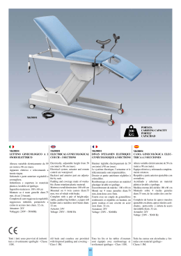
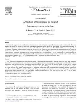
L010125H86 - 0404
42N - FAN COIL UNITS
2-way valve kit
installation instructions
42N - VENTILCONVETTORI
Istruzioni di installazione
kit valvole a 2 vie
42N - VENTILO-CONVECTEURS
Instructions d’installation
kit vannes à 2 voies
42N - VENTILATOR-KONVEKTOREN
Installationsanweisungen
Satz 2-Wege-Ventile
42N - UNIDADES FAN COIL
Instrucciones de instalación
kit válvulas de 2 vías
햲
햳
Ref.
Q.ty
Rif.
Q.tà
Ref.
Q.té
Bez. Anz.
DESCRIPTION
햴
DESCRIZIONE
DESCRIPTION
BESCHREIBUNG
DESCRIPCIÓN
Ref. Can.
햲
햳
1
1
Inlet pipe
Outlet pipe
햴
1
Installation instruction
Tubo entrata
Tubo uscita
Eingangsrohr
Ausgangsrohr
InstallationsIstruzioni di installazione Consignes d’installation
anweisungen
Tuyau entrant
Tuyau sortant
Tubo de entrada
Tubo de salida
Instrucciones de
instalación
Example of left-hand kit assembly - Rappresentazione di montaggio kit
Exemple de montage kit à gauche - Montagedarstellung Satz (links)
Representación de montaje kit IZDO
Water inlet
Entrata acqua
Entrée d'eau
Wassereintritt
Entrada de agua
Water outlet
Uscita acqua
Sortie d'eau
Fig./Abb. 2
Wasserablauf
Fig./Abb. 3
Salida de agua
Assembly
Montaggio
• Remove the cabinet (if any).
• During assembly, make sure the O-rings
are properly mounted on the pipe flange
so that perfect sealing is guaranteed.
• Assemble the group to the coil as shown
in fig. 2 and 3 (For left-hand version).
• For right-hand version:
Turn the valve of 180° until the
electrothermal head is turned towards the
mounting brackets.
• Tighten the nipples to the manifolds of the
coil to 30 Nm (fig. 2).
• Connect the electric cable from the
thermoelectric valve head to the electric
panel following the diagram attached to
the panel inside.
• Re-install the cabinet (if any).
Note:
To install this kit, it is necessary to buy the
basin kit too.
• Rimuovere il mobile se presente.
• Durante l'assemblaggio verificare che gli
O-Ring siano inseriti sulla cartella del tubo
in modo da assicurare una perfetta tenuta.
• Assemblare il gruppo sulla batteria come
indicato nelle figure 2 e 3 (Per versione SX).
• Per versione DX:
Ruotare valvola di 180° affinché risulti
rivolta con testa elettrotermica verso le
staffe di apprensione.
• Serrare i nipli nei collettori presenti sulla
batteria con una coppia di 30 Nm, come
indicato in fig 2.
• Collegare il cavo elettrico della testa
elettrotermica al quadro elettrico seguendo
lo schema elettrico applicato all'interno
dello stesso.
• Rimontare il mobile se presente.
Nota: Per l'installazione del presente kit è
necessario anche l'acquisto del kit bacinella.
Montage
Montage
Montaje
• Enlever le cabinet (s’il n’y en a un).
• Lors du montage, vérifier la présence des
joints toriques montés sur la bride de
retenue du tuyau, de façon à garantir une
étanchéité totale.
• Monter donc le groupe sur la batterie
comme indiqué dans les figures 2 et 3.
(Pour version à gauche).
• Pour version à droite:
Tourner la vanne de 180° jusqu’à ce que
la tÍte électrothermique est tournée en
direction des étriers de suspension.
• Serrer les nipples dans les collecteurs
présents sur la batterie à l’aide d’un couple
de 30Nm, comme indiqué dans la fig. 2.
• Brancher le câble électrique de la tête de
la soupape thermoélectrique au panneau
électrique suivant le schéma à l’intérieur
de celui-ci.
• Remonter le cabinet, s’il n’y en a un.
Note :
L’installation de ce kit prévoit également
l’achat du kit bassin de drainage.
• Das Gehäuse, falls vorhanden, entfernen.
• Während dem Zusammenbau überprüfen,
dass die O-Ringe auf dem Rohr eingeführt
sind, so dass eine perfekte Dichtheit
gewährleistet wird.
• Die Gruppe auf der Batterie zusammenbauen,
wie in Abbildungen 2 und 3 angezeigt.
(für Ausführung links).
• Für rechte Ausführung:
Ventil um 180° umdrehen, so dass es mit
dem thermoelektrischer Kopf gegen die
Befestigungsbügel gerichtet ist.
• Die Nippel in die Konnektoren der Batterie
mit einem Drehmoment 30 Nm anziehen,
wie in Abbildung 2 angezeigt.
• Das elektrische Kabel des
elektrothermischen Kopfes am Schalttafel
nach dem darin enthaltenen Schaltplan
anschließen.
• Das Gehäuse, falls vorhanden, wieder
montieren.
Hinweis: Zur Installation dieses Satzes ist es
notwendig, den Satz "Wanne"zu kaufen.
• Retirar el mueble si existe.
• Durante el ensamblaje verificar que las
juntas tóricas estén introducidas en la aleta
del tubo para asegurar una perfecta
estanqueidad.
• Ensamblar el grupo sobre la batería como
está indicado en las figuras 2 y 3.
(Para versión IZDA).
• Para versión DCHA:
Girar la válvula de 180° de tal manera que
la cabeza electrotérmica quede dirigida
hacia las bridas de suspensión.
• Apretar los niples en los tubos de
distribución presentes en la batería con un
par de 30 Nm, como está indicado en la fig 2.
• Conectar el cable eléctrico de la cabeza
electrotérmica al cuadro eléctrico siguiendo
el esquema eléctrico aplicado en el interior
del mismo.
• Volver a montar el mueble, si existe.
Nota:
Para la instalación de este kit es necesario
comprar también el kit de la bandeja.
The manufacturer reserves the right to change any product specifications without notice.
La cura costante per il miglioramento del prodotto può comportare senza preavviso, cambiamenti o modifiche a quanto descritto.
Le fabricant se réserve le droit de modifier les spécifications du produit, sans préavis.
Änderungen im Zuge der technischen Weiterentwicklung vorbehalten.
El fabricante se reserva el derecho de cambiar las especificaciones de los productos sin previo aviso.
Carrier S.p.A. - Via R. Sanzio, 9 - 20058 Villasanta (MI) Italy - Tel. 039/3636.1
April, 2004. Supersedes December 2002.
Printed in Italy
2
Scaricare