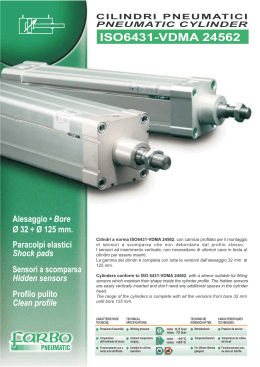
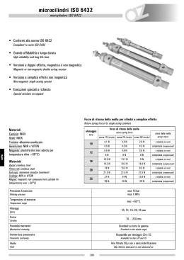
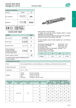
1
1.02.00
MICROCILINDRI PNEUMATICI A NORME ISO 6432
6432 ISO PNEUMATIC MICROCYLINDERS
CARATTERISTICHE COSTRUTTIVE / FEATURES ON STRUCTURE
TESTATE in alluminio anodizzato
Anodized aluminium HEADS
BUSSOLA in bronzo sinterizzato autolubrificante
SeIf-Iubricating sinterized bronze BUSH
PISTONE in ottone
Brass PISTON
CANNA cilindro in AISI 304, rullata sulla testata anteriore e posteriore
AISI 304 cylinder BARREL, with rolled front and rear heads
STELO in AISI 304 rullato
Rolled AISI 304 ROD
GUARNIZIONI in nitrile prelubrificate per minimo attrito, lunga vita e utilizzi in aria non lubrificata.
Per applicazioni in alta temperatura, vengono utilizzate guarnizioni in viton.
SEALS: special nitril prelubricated for minimum friction, Iong-Iife and non-Iube service.
For high temperature appIication viton seals can be incorporated
AMMORTIZZATORI di fine corsa presenti nei microcilindri Ø 20 - 25
Short stroke DAMPERS on Ø 20-25 microcylinders
PARACOLPI di fine corsa su tutti i microcilindri
Short stroke SHOCK ABSORBES on all microcylinders
I microcilindri Ø 16 - 20 - 25 sono predisposti di serie per fine corsa magnetici
Ø 16-20-25 microcylinders are arranged for magnetic stroke limit
Pressione nominale di esercizio
Nominal working pressure
:
:
min. 1 bar max 10 bar
Fluido
Fluid
:
:
aria compressa filtrata, con o senza lubrificazione
fiItered, compressed air, either with or without Iubrication
Temperatura d’impiego
Working temperature
:
:
-10 C +80 C
Alesaggi Ø
Bores
:
:
8 - 10 - 12 – 16 – 20 – 25
°
°
SEZIONE UTILE PER IL CALCOLO DELLA FORZA DEL CILINDRO
USABLE SECTION IN ORDER TO CALCULATE THE CYLINDER FORCE
CORSE DI AMMORTIZZAMENTO
DAMPING STROKES
Ø
8
10
12
16
20
25
Alesaggio Ø mm. / Bore Ø mm.
20
25
Di spinta
0,50
0,78
1,13
2,01
3,14
4,9
Stelo Ø mm. / Rod Ø mm.
8
10
Di tiro
0,37
0,66
0,84
1,72
2,63
4,12
Corse / Strokes
18
21
AREA cm
2
Calcolo del consumo d’aria in NL/min. dei cilindri pneumatici
Calculation of air consumption of pneumatic cylinders, in NL/min.
Qn = (Ss + St) x H x N x (P + 1)
1000
1.02.01
Qn
=
Consumo aria cilindro (NL/min.)
Air consumption of cylinder (NL/min.)
Ss
=
Superficie lato spinta (cm )
Thrust side surface (cm2)
St
=
Superficie lato trazione (cm )
Tensile stress side surface (cm2)
P
=
Pressione di lavoro relativa(bar)
Gauge working pressure (bar)
H
=
Corsa cilindro (cm.)
Cylinder stroke (cm.)
N
=
Numero cicli al minuto
Number of cycles /min.
P+1
=
Pressione assoluta (bar)
Absolute pressure (bar)
2
2
MICROCILINDRI PNEUMATICI A NORME ISO 6432
6432 ISO PNEUMATIC MICROCYLINDERS
DIMENSIONI D’INGOMBRO I OVERALL SIZE
MICROCILINDRO A STELO SEMPLICE / SIMPLE ROD MICROCYLINDER
1
MICROCILINDRO A STELO PASSANTE I THROUGH ROD MICROCYLINDER
DIM
Ah7
B
BE
CH CH1 CH2 D-2
8
4
12
M12
x
1,25
-
7
19
10
4
12
M12
x
1,25
-
7
12
6
18
M16
x
1,5
5
16
6
18
M16
x
1,5
20
8
20
25
10
22
L3 Md13
N
OH9 QR
E
F
G
H
I
L
L1
L2
12
4
16
16
M5
15
46
70
86 102
8
6
4
19
12
4
16
16
M5
15
46
70
86 102
8
6
10
24
16
4
20
20
M5
19
50
84 104 124 12
5
10
24
16
4
20
20
M5
19
56
M22
X
1,5
6
13
32
20
4
24
27 G /8 25
M22
x
1,5
8
17
32
22
6
28
WF±1,2 XC±1 KK
R
S
S1
78
10
3
7
16
64
M4
4
78
10
3
7
16
64
M4
8
6
92
10
5
8
22
75
M6
89 109 129 12
9
6
97
10
5
8
22
82
M6
67 107 131 155 16
12
8
115 16
5
10
24
95
M8
31 G /8 29,5 69 113 141 169 16
12
8
125 16
6
10
28
104
M10
x
1,25
Ø
1
1
1.02.02
MICROCILINDRI PNEUMATICI A NORME ISO 6432
6432 ISO PNEUMATIC MICROCYLINDERS
DISPOSITIVI DI FISSAGGIO / FIXING DEVICES
FISSAGGIO A PIEDINI tipo MF-4 / FEET FASTENING type MF-4
FISSAGGIO A FLANGIA tipo MF-8 I FLANGE FASTENING type MF-8
FISSAGGIO AD ARTICOLAZIONE tipo MF-2 / JOINT FASTENING type MF-2
SNODO tipo S I JOINT type S
FORCELLA tipo CFV I FORK type CFV
DIM
F FA FD FI FM FN P PA PD PF PG PI PM PN PR PV PZ
R TF TG TW W WP X XE XI XY KK KR KW KZ Y YA YD YH YI YN YO YR YU YV YW YZ YZ1
Ø
8
21 11 4
8 16
8 3 11
4 24 12.5 2.5 16.5 13
5 20 62.5 10 30 40 25 13 65
5
68 30 24 M4 25 35 16 5 8
27
9
4 11 4.5 9
6
10 36
5
4
10 21 11 4
8 16
8 3 11
4 24 12.5 2.5 16.5 13
5 20 62.5 10 30 40 25 13 65
5
68 30 24 M4 25 35 16 5 8
27
9
4 11 4.5 9
6
10 36
5
4
12 31 16 6 12 24 12 4 13
6 27 15
3
22
18
7 25 73 13 40 53 30 18 76
8
78 30 32 M6 32 42 20 6 9
30 11 5 13 5.5 10 6.75 12 40
6
6
16 31 16 6 12 24 12 4 13
6 27 15
3
22
18
7 25 80 13 40 53 30 18 82
8
84 36 32 M6 32 42 20 6 9
30 11 5 13 5.5 10 6.75 12 40
6
6
20 42 22 8 16 32 16 5 16
8 30 20
4 28.5 24 10 32 91 20 50 66 40 19 96
8
8
25 52 26 10 20 40 20 5 16
8 30 20
4 28.5 24 10 32 100 20 50 66 40 23 102 11 103 45 40
1.02.03
7 101 43 36 M8 40 54 25 8 12 36 14 6 16 6.6 12
9
16 48
M10
x 40 54 25 8 14 43 17 6 19 6.6 14 10.5 20 57 10 10
1.25
MICROCILINDRI PNEUMATICI A NORME ISO 6432
6432 ISO PNEUMATIC MICROCYLINDERS
INTERRUTTORI MAGNETICI DI PROSSIMITA’ I PROXIMITY MAGNETIC SWITCHES
FINE CORSA MAGNETICO tipo FEK I MAGNETIC STROKE LIMIT type FEK
1
Supporto sensore per alesaggio ø 16 cod. SMF-16 I Sensor support for bore ø 16 cod. SMF-16
Supporto sensore per alesaggio ø 20 cod. SMF-20 I Sensor support for bore ø 20 cod. SMF-20
Supporto sensore per alesaggio ø 25 cod. SMF-25 I Sensor support for bore ø 25 cod. SMF-25
contatto I contact
- classe di protezione (DIN 40050)
- protection class (DIN 40050)
IP65
Indicazione di commutazione
switching indication
LED
Tensione nominale I rated voltage
- corrente continua / direct current
- corrente alternata I alternating current
- caduta di tensione max. I max voltage drop
V dc
V ac
V
3…250
3…250
2,5
Valori di commutazione (2) / switching ratings (2)
- potenza max. in cc / max power in dc
- potenza max. in ac / max power in ac
- corrente max. a 25 °C (carico resistivo)
max current at 25 °C (resistive Ioad)
W
VA
mA
50
50
1000
Protezione contro I protection against
- picchi di tensione induttivi / inductive peaks of voltage
- polarità inversa / reverse polarity
Vr
250
idoneo
carico max. applicabile (limite di sicurezza) (3)
max applicable Ioad (safety Iimits) (3)
- bobina con soppressore di sovrappesi
coil with overvoltage suppressor
- bobina semplice / simple coil
- PLC / PLC
W
10
W
10
idoneo
altri dati / other data
- vita elettrica (4)
(carico resistivo 20% della potenza max., distanza breve
tra carico e interruttore)
- electric Iife (4)
(resistive load 20% pf max power, short distance between
load and switch)
- ripetibilità / repeatability
- tempo di azionamento (carico resistivo)
operating time (resistive load)
- tempo di rilascio (carico resistivo)
release time (resistive load)
- temperatura di uso / working temperature
- resistenza all’urto (11 ms) / impact strength (11 ms)
- resistenza alle vibrazioni / vibration resistance
NB.
Nx106
10
mm
ms
0,1
2
ms
0,1
°C
g
Hz
-30 / +80
50
1000
(2) Solo per i reed - la corrente, la potenza e la tensione massima di
commutazione sono dei valori di riferimento che definiscono la
robustezza del reed stesso da un punto di vista elettrico. Questi valori
sono calcolati sperimentalmente per una vita elettrica media di circa
5
5 x 10 cicli. Con carichi inferiori è possibile ottenere una vita elettrica
molto più lunga.
(3) Con la stessa potenza, a bassa tensione otteniamo una corrente
alta (P=Vxl). Verificare se viene superata la “corrente max”. I valori
esposti si riferiscono alle bobine normalmente sul mercato (carichi
induttivi).
Per fare un circuito di prova: sostituire il carico L con un LED e una
resistenza. Valore della resistenza: per V = 24 volt: 2200 ohm, 1/4 watt;
per V=110...250 volt: 33000 ohm, 2 watt.
SUGGERIMENTO. Non usare lampadine a filamento perchè possono
danneggiare l’interruttore. Un circuito di prova molto semplice e veloce
può essere realizzato collegando un connettore con LED (senza
elettrovalvola) in serie all’interruttore. Il connettore contiene già un LED
e una resistenza adatta.
(4) La vita elettrica dell’interruttore è molto influenzata dal tipo di carico
e dal tipo di collegamento tra carico e interruttore.
(2) For reed only - the maximum switching current, power and voltage
are reference values which define the strength of the reed itself from the
electrical point of view. These values are calculated experimentally for
an average electric life of about 5 x 10⁵ cycles. With lower Ioad values a
much longer life is obtained.
(3) With the same power, at low voltages we get high currents
(P = V x I). Check if the “max current” is exceeded. The values shown
are referred to the coils normally on the market (inductive Ioads)
To make a test circuit: replace the load L with a LED and a resistor.
Value of the resistor:
for V = 24 volt: 2200 ohm, 1/4 watt; for V= 100…250 volt: 33000 ohm,
2 watt.
HINT. Do not use filament lamps since they could damage the switch. A
very simple, quick test circuit can be obtained by connecting connector
with LED (without solenoid valve) to the switch in series. The connector
already contains a suitable LED and resistor.
(4) The electric life of reeds is influenced to a large extent by the type of
load and the type of connection between load and switch.
Per le caratteristiche tecniche consultare il paragrafo “Sensori magnetici” pag. 1.13.00
For Tecnhnical features refer to “Magnetic sensor” 1.13.00 page
1.02.04
MICROCILINDRI PNEUMATICI A NORME ISO 6432
6432 ISO PNEUMATIC MICROCYLINDERS
INTERRUTTORI MAGNETICI DI PROSSIMITA’ I PROXIMITY MAGNETIC SWITCHES
Adatti per essere montati su:
cilindri ISO 6431 serie /
ISO 6431 cylinders series
EU2
For to be assembled:
cilindri compatti serie /
compact cylinders series
CBU
microcilindri ISO serie /
ISO microcylinders series
ME*
* con staffe di ancoraggio
*with sensor support
tipo SM5L / type SM5L
MONTAGGIO DEL SENSORE
Assembly of the sensor
2 mt.
MARRONE / Brown
SM5L
5-130Vac/dc 6W
BLU / Blue
Con apposite staffe di fissaggio tipo SFM
per un minimo ingombro
With sensor support type SFM for
minimum dimensions
TIPO SM5L-300-M8 / type SM5L-300-M8
300 mm
M8
OUT
4
IN
SM5L-300-M8
5-50Vac/dc 6W
1
3
Marrone / Brown = IN
contatto I contact
Indicazione di commutazione
switching indication
LED
SM5L
5-130Vac/dc 6W
tipo SM5L / SM5L type
Blu / Blue = OUT
Tensione nominale I rated voltage
- corrente continua / direct current
- corrente alternata I alternating current
- versione con connettore M8
- version with M8 connector
- caduta di tensione max. I max voltage drop
V dc
V ac
V ac
Corrente di azionamento / operating current
mA
200
Carico max. applicabile / max applicable load
W
VA
6
6
V
5…130
5…130
5…50
3
107
Vita elettrica (carico resistivo)
Electric life (resistive load)
Tempo di azionamento / operating time
ms
0,5
Tempo di rilascio / release time
ms
0,2
Temperatura ambiente / room temperature
Cavo fisso / fixed cable
Cavo mobile / mobile cable
°C
°C
-20… +60
-5… +60
Lunghezza cavo / lenght cable
Mt
2
NB.
1.02.05
OUT
4
tipo SM5L-300-M8
SM5L-300-M8 type
IN
1
3
Gli interruttori magnetici SM5L sono sensori di prossimità elettrici.
L’avvicinarsi di un campo magnetico determina l’azionamento del
contatto Reed presente nel circuito del sensore.
Il sensore va sempre collegato in serie al carico.
Il sensore è anche disponibile nella versione a 3 fili e nella versione con
la parte terminale del cavo con connettore normalizzato M8.
Per il fissaggio del sensore sul cilindro occorrono le staffe:
tipo SFM 16 per il microcilindro ME 16
tipo SFM 20 per il microcilindro ME 20
tipo SFM 25 per il microcilindro ME 25
Magnetic switches SM5L are proximity electric sensor. The approach of
a magnetic field determines the control of the reed contact that is in the
sensor’s circuit. The sensor is always connect in series to the load.
The sensor can be available in a version with three thread and in that
with the end of the hollow with normalized M8 connector.
For fixing the sensors, is necessary sensor support:
type SFM 16 for ME 16 microcylinder
type SFM 20 for ME 20 microcylinder
type SFM 25 for ME 25 microcylinder
Per le caratteristiche tecniche consultare il paragrafo “Sensori magnetici” pag. 1.13.00
For Tecnhnical features refer to “Magnetic sensor” 1.13.00 page
MICROCILINDRI PNEUMATICI A NORME ISO 6432
6432 ISO PNEUMATIC MICROCYLINDERS
FORME COSTRUTTIVE STANDARD I STANDARD BUILD SHAPES
Ø
VERSIONE
8
10
12
•
•
•
16
20
FORMA COSTRUTTIVA
BUILDING SHAPE
25
1
A STELO SEMPLICE /SIMPLE ROD
ME _________
A STELO SEMPLICE MAGNETICO / MAGNETIC SIMPLE ROD
•
•
•
ME _________
A STELO PASSANTE / THROUGH ROD
•
MEK _________
A STELO PASSANTE MAGNETICO / MAGNETIC THROUGH ROD
•
•
•
MEK _________
•
•
MA _________
•
•
MAK _________
•
•
MES _________
A STELO SEMPLICE AMM.TO MAGNETICO / MAGNETIC DAMPING SIMPLE ROD
A STELO PASSANTE AMM.TO MAGNETICO / MAGNETIC DAMPING THROUGH ROD
A SEMPLICE EFFETTO / SIMPLE ACTING
•
I microcilindri Ø 16-20-25 sono predisposti di serie per fine corsa magnetici / Ø 16-20-25 microcylinders are arranged for magnetic stroke limit.
CORSE STANDARD PER MICROCILINDRI A STELO SEMPLICE
STANDARD STROKE FOR SIMPLE ROD MICROCYLINDERS
CORSA
Ø
8
10
12
16
20
25
10
25
40
50
80
100
125
160
200
250
320
•
•
•
•
•
•
•
•
•
•
•
•
•
•
•
•
•
•
•
•
•
•
•
•
•
•
•
•
•
•
•
•
•
•
•
•
•
•
•
•
•
•
•
•
•
•
•
•
•
•
Corse standard per microcilindri a semplice effetto molla anteriore Ø 16-20-25, corsa 10-20-30-40-50
Standard strokes for simple acting microcylinders front spring Ø 16-20-25, stroke 10-20-30-40-50.
N.B. Il microcilindro mantiene lo stesso ingombro della versione a stelo semplice. / This microcylinder keeps the same overall size of the simple rod one
NORME PER L’ORDINAZIONE:
How to fill in your order:
ME
20
Forma costruttiva / building shape Alesaggio / bore
100
Corsa / stroke
I fissaggi vengono forniti a parte con riferimento al tipo / Fastenings are supplied separately with reference to th type
1.02.06
Scaricare