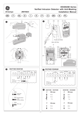
BMDMD-707
Italiano
Rivelatore a specchio per installazione esterna con
antimascheramento
English
Outdoor Mirror Detector with Anti-Mask
LED
Figura 1. Vista generale BMD-707
Figura 1. BMD-707 – General view
ITALIANO
1. INTRODUZIONE
• 8 sensori PIR indipendenti brevettati che lavorano in configurazione Quad con sistema di elaborazione del segnale “true motion recognition” (TMR) su
ogni singolo sensore PIR. Le informazioni vengono poi rielaborate insieme così da distinguere il movimento prodotto da un intruso dal movimento
prodotto da alberi e cespugli.
• Ottica Advance Obsidian Black MirrorTM (in corso di brevetto).
• Alta protezione contro neve, pioggia, polvere e luce diretta del sole.
• Protezione antisabotaggio contro l'apertura e la rimozione dal muro.
• LED d'allarme visibile anche di giorno.
• Rilevazione bassa tensione
• Autotest
• Contenitore robusto con finestra ottica incassata.
• Rilevazione antimascheramento in grado di distingue il mascheramento da spray dalla pioggia.
• Immunità agli animali fino a 18 Kg.
• Staffa snodabile incorporata.
2. INSTALLAZIONE
2.1 Configurazione DIP-SWITCH
Rimuovere le due coperture sotto al sensore (come illustrato in Figura 3, fasi 4-8) per accedere ai DIP- SWITCH. Configurare i microinterruttori come
indicato di seguito nella Tabella 1:
Tabella 1 – Impostazione degli interruttori DIP
Int. DIP #
Funzione
Descrizione
Predefinita
1
LED OFF/ON
OFF: LED allarme intrusione e mascheramento disabilitato (OFF). Può essere attivato
ON
tramite l’ingresso TST (Attivo "basso")
ON: LED allarme intrusione e mascheramento abilitato (ON).
2
Sensibilità PIR
OFF: Sensibilità PIR normale.
OFF
ON: Sensibilità PIR alta.
3
AM ON / OFF
ON: AM attivo
ON
OFF: AM non attivo*
4
Mascheramento attiva l’uscita OFF: l'evento di mascheramento è riportato in centrale come GUASTO (apre solo l’uscita di
OFF
di allarme (Standard EN)
guasto)
ON: l'evento di mascheramento è riportato in centrale come GUASTO ed ALLARME (Standard
EN). L’uscita di guasto e di allarme vengono attivate allo stesso tempo.**
* Passando da OFF a ON si ripristina il rivelatore per un periodo di stabilizzazione di 60 secondi e si induce il rivelatore a riadattarsi alle condizioni
ambientali correnti. Restare alla distanza di almeno 0,5 m dal rivelatore per evitare disturbi durante questo processo.
** Impostare su ON per le centrali e le installazioni approvate EN. Tuttavia molti installatori preferiscono non avere l’uscita di ALLARME attivata in caso di
mascheramento.
2.2 Installazione
Installazione staffa (come illustrato in figura 3) – fissare saldamente la staffa su una parete stabile o su una colonna. La staffa deve essere fissata il
più parallela possibile alla superficie dell’area sorvegliata.
Eseguire i collegamenti elettrici (come illustrato in figura 3, passi 8 - 10)
Regolare l’inclinazione orizzontale e verticale del rilevatore (come illustrato in Fig. 4, passi 1 – 6), in funzione dell’area sorvegliata da coprire e chiudere il
rilevatore come illustrato in Fig. 3, passi 7 – 12. La corretta inclinazione verticale varia in funzione della dell’altezza di montaggio e della distanza di copertura
da garantire.
Nella tabella 2 è mostrata la relazione tra l’inclinazione verticale e le diverse altezze di installazione (le informazioni si riferiscono ad una area con superficie
piana. Ad ogni modo, l’inclinazione verticale deve essere verificata eseguendo la prova di copertura).
Altezza di montaggio
3,0 m
2,5 m
2,0 m
1,5 m
Tabella 2 – Riferimenti per la regolazione dell'inclinazione verticale
Distanza di copertura
2m
4m
6m
8m
10 m
1
2
2
3
1
1
2
3
4
1
2
3
4
5
2
3
4
5
-
D-304960 BMD-707 Istruzioni di installazione / Installation Instructions
12 m
3
4
5
-
1
2.3 Test
A. Il rivelatore attiva la modalità ”Prova di Copertura” dopo che hanno
avuto luogo una delle seguenti condizioni:
- Il periodo di stabilizzazione di 60 secondi ha termine.
- La posizione del DIP DWITCH 1 cambia da OFF a ON.
- Lo stato dell’ingresso TST cambia da OFF a ON.
NOTA: a prescindere dallo stato dell’ingresso TST e del DIP-SW1, le
indicazioni dei LED di Allarme e AM sono attive durante la modalità
”Peova di Copertura”. Attraversando un solo raggio si provoca il
doppio lampeggio del LED rosso.
B. Attraversare l’area protetta nel punto più lontano. Verificare che ad
ogni movimento rilevato dal sensore, il LED si accenda per 2 secondi
e che la centrale riceva l’allarme. Se necessario, eseguire
nuovamente la regolazione orizzontale / verticale.
Importante! Istruire l’utente ad eseguire la Prova di Copertura almeno
una volta alla settimana, per verificare il corretto funzionamento.
C. Posizionare un pezzo di cartone di fronte al rilevatore, per
mascherare deliberatamente la finestra ottica. Dopo 2 minuti, il LED
giallo si accenderà (come indicato nella Tabella 3) e la centrale
riceverà l’allarme mascheramento.
D. Rimuovere il cartone dalla parte frontale del rilevatore. Il LED
smetterà di lampeggiare (dopo circa 30 secondi).
Tabella 3 – LED Funzionamento
Evento / stato
Indicazione
Bassa tensione
Rosso intermittente
Riscaldamento (60 sec.)
Giallo + rosso intermittenti alternativamente
Auto-test fallito
Giallo + rosso intermittenti simultaneamente
Rilevazione AM
Giallo acceso
ALLARME
Rosso acceso per 2 sec.
Tabella 4 – Uscite del relè
Evento / stato
Uscita relè
Problema
Allarme
Mancanza alimentazione
Aperto
Aperto
Riposo - Stand-by
Chiuso
Chiuso
Rilevazione bassa tensione
Aperto
Chiuso
Auto-test fallito
Aperto
Chiuso
Rivelazione AM DIP-SW4=ON Aperto
Aperto
Rivelazione AM DIP-SW4=OFF Aperto
Chiuso
Allarme
Chiuso
Aperto per 2 sec.
2.4 Chiusura coperchio
Come illust. in Fig. 4, passi 7-10.
3. AVVERTENZE
Questa apparecchiatura genera, fa uso e può irraggiare energia a radio-frequenza e, se non installata ed usata secondo le istruzioni, può provocare
dannose interferenze alle comunicazioni radio. Non vi è quindi la certezza che non avvengano interferenze in un determinato impianto. Se questa
apparecchiatura provoca interferenze dannose alla ricezione radio o TV, cosa questa che può essere verificata accendendo e spegnendo
l’apparecchiatura, si suggerisce all’utente di tentare di rimediare all’interferenza applicando una o più delle misure che seguono:
– Orientare diversamente o spostare l’antenna ricevente.
– Aumentare la distanza che intercorre tra questa apparecchiatura e l’apparecchio ricevente.
– Collegare questa apparecchiatura ad una presa che appartiene ad un circuito diverso da quello a cui è collegato l’apparecchio ricevente.
– Richiedere l’assistenza del rivenditore oppure quella di un esperto tecnico elettronico.
Avviso! Modifiche non espressamente approvate dalla BENTEL SECURITY possono invalidare l'autorizzazione concessa all'utente all'uso di questa
apparecchiatura nel quadro dei regolamenti.
INFORMAZIONI SUL RICICLAGGIO
BENTEL SECURITY consiglia ai clienti di smaltire i dispositivi usati (centrali, rilevatori, sirene, accessori elettronici, ecc.) nel rispetto dell’ambiente.
Metodi potenziali comprendono il riutilizzo di parti o di prodotti interi e il riciclaggio di prodotti, componenti e/o materiali.
Per maggiori informazioni visitare: http://www.bentelsecurity.com/index.php?o=enviromental
DIRETTIVA RIFIUTI DI APPARECCHIATURE ELETTRICHE ED ELETTRONICHE (RAEE – WEEE)
Nell’Unione Europea, questa etichetta indica che questo prodotto NON deve essere smaltito insieme ai rifiuti domestici. Deve essere depositato in un
impianto adeguato che sia in grado di eseguire operazioni di recupero e riciclaggio
Per maggiori informazioni visitare: http://www.bentelsecurity.com/index.php?o=enviromental
APPENDICE: SPECIFICHE
OTTICA
Black Mirror - Copertura massima:
Tecnologia di rivelazione
Immunità animali domestici
DATI ELETTRICI
Alimentazione:
Assorbimento a riposo:
Assorbimento in funzione:
Rilevamento bassa tensione:
Uscite:
Uscita di allarme:
Uscita di guasto:
Uscita sabotaggio:
Ritardo nella rivelazione di
mascheramento:
Ingresso per attivazione remota del
LED (TST):
MONTAGGIO
Tipo di montaggio:
Altezza di montaggio:
Regolazione verticale:
Regolazione orizzontale:
DATI AMBIENTALI
Temperatura di funzionamento:
Temperatura di stoccaggio:
Umidità:
Immunità luce bianca:
DATI FISICI
Dimensioni (altezza x lunghezza x
larghezza):
Peso:
Colore:
CONFORMITÀ
Brevetti USA:
2
Almeno 12 metri / 90º.
8 sensori PIR indipendenti funzionanti in configurazione Quad.
Fino a 18 kg
8-16 Vcc
15 mA a 12 Vcc.
70 mA max. (con LED giallo e rosso accesi)
quando la tensione di alimentazione scende sotto 7,5 Vcc
Vista dall’alto
9m
6m
90°
3m
0
Relè a stato solido. NC, 100 mA / 30 V, massima resistenza interna di 35 ohm.
(Come illustrato in Tabella 4)
Relè a stato solido. NC, 100 mA / 30 V, massima resistenza interna di
35 ohm. (Come illustrato in Tabella 4)
deviatore NC, 50 mA / 30 Vcc. "Aperto" all’apertura del coperchio o
staccandolo il rivelatore dalla superficie sulla quale è installato.
120 secondi
3m
6m
9m
0
3
6
9
12 m
Vista laterale di ciascum rilevatore
Ingresso ad alta impedenza. Interagisce con il LED solo se il selettore interno
LED è impostato su OFF.
montaggio a parete
1,5 – 3,0 metri
Da 0º a -10º, con passi di 2,5º.
Da -45º a +45º, con passi di 5º.
2.4 m
0
3
6
9
12 m
Fig. 2 – Diagramma di copertura
da -35°C a 60°C
da -35°C a 60°C
95% max.
oltre 25000 lux
157x147x124 mm.
600 g
Bianco
EN 50130-4, EN 60950, EN 50130-5 classe ambientale IV. IP 55.
7250605, 6818881, 5693943. Altri brevetti in via di approvazione.
D-304960 BMD-707 Istruzioni di installazione / Installation Instructions
ENGLISH
1. INTRODUCTION
• Patented 8 independent quad PIR detectors operating in true Quad configuration with true motion recognition (TMR) processing for each of the 8 PIR
detectors and central motion processing - can distinguish between a moving intruder and moving trees and bushes.
• Advance Obsidian Black MirrorTM optics (patent pending).
• High protection against snow, rain, dust, wind and direct sunlight.
• Tamper protection against opening and removal from wall.
• Alarm LED is visible in sunlight.
• Low voltage detection
• Self test
• Robust housing with recessed window.
• Smart anti masking can distinguish between masking spray and rain.
• Immunity to pets weighing up to 18 Kg, not pet alley.
• Built in swivel bracket.
2. INSTALLATION
2.1 DIP Switches Setup
Remove the 2 detector's bottom covers (see Figure 3, steps 4-8) to gain access to the DIP switches. Set the DIP switches, according to Table 1.
Table 1 – DIP Switch Setup
DIP SW # Function
Description
Default
OFF: Motion and masking alarm LEDs is disabled (OFF). Can be enabled by TST input
1
LED OFF/ON
ON
(Active "low")
ON: Motion and masking alarm LEDs is enabled (ON).
2
PIR Sensitivity
3
AM OFF / ON
OFF: Normal PIR sensitivity.
ON: High PIR sensitivity.
OFF: AM off
ON: AM on *
OFF
ON
OFF
OFF: masking event reported to panel as TROUBLE (Trouble relay opens).
ON: masking event reported to panel as TROUBLE and ALARM (EN standard). Trouble
and Alarm relay opens at the same time.**
* Switching from OFF to ON resets the detector for a stabilization period of 60 sec. and causes the detector to re-adapt to its current surroundings.
Remain at a distance of at least 0.5 m from the detector to prevent disruption of this process.
** Use ON for EN approved control panels / installations. However, many installers prefer not to have the ALARM relay opened on a masking event.
4
Masking event opens Alarm
relay (EN standard)
2.2 Installation
Bracket installation (see figure 3) – firmly fix the bracket on a stable wall or pillar. The orientation of the fixed bracket should be as parallel as possible
to the surveyed ground surface.
Perform wiring (see figure 3, step 8 - 10)
Adjust detector's horizontal and vertical angles (see Fig. 4, steps 1 - 6), according to the surveyed ground surface and close the detector, as shown in Fig. 3,
steps 7 - 12.
The vertical angle indicator position for various installation height and coverage distance combinations is detailed in Table 2 (the information refers to a
relatively flat surveyed area. however, in any case the vertical adjustment should be verified by walk-test).
Table 2 - Vertical Adjustment Reference
Mounting Height
3,0 m
2,5 m
2,0 m
1,5 m
2m
1
1
2
4m
1
1
2
3
2.3 Test
A. The detector enters Walk-Test mode after one of the following
occurs:
- The 60-second stabilization period ends.
- DIP-SW1 position changes from OFF to ON.
- TST input state changes from OFF to ON.
NOTE: Regardless of the DIP-SW1 and TST input settings, the Alarm
and AM LED indications are enabled in Walk-Test mode.
Crossing a single beam causes the red LED to double-blink.
B. Walk into the detector's field of view at the expected far edge of the
coverage area. Verify that each time your motion is detected the red LED
lights for 2 seconds and the control panel receives the alarm. If required,
perform detector's horizontal / vertical readjustments.
Important! Instruct the user to perform walk test at least once a week, to
verify proper operation of the detector.
C. Place a piece of cardboard on the detector’s front side, to
deliberately mask the optical window. After 2 minutes, the yellow LED
should light (see Table 3) and the alarm control panel should receive the
masking alarm.
D. Remove the masking from the detector’s front side. The LED should
extinguish (after about 30 seconds).
6m
2
2
3
4
Coverage Distance
8m
2
3
4
5
10 m
3
4
5
-
12 m
3
4
5
-
Table 3 – LED Operations
Event / status
Indication
Low voltage
Red flashing
Warm-up (60sec.)
Yellow + Red flashing alternately
Self-test failure
Yellow + Red flashing simultaneously
AM detection
Yellow ON
ALARM
Red ON for 2 sec.
Crossing Beam during
Red Double blink
Walk-Test
Table 4 – Relay Outputs
Event / status
Relay Output
Trouble
Alarm
Complete power failure
Open
Open
Standby
Closed
Closed
Low voltage
Open
Closed
Self-test failure
Open
Closed
AM detection DIP-SW4 = ON
Open
Open
AM detection DIP-SW4 = OFF Open
Closed
Alarm
Closed
Open for 2 sec.
2.4 Cover Closure
See fig. 4, steps 7-10.
D-304960 BMD-707 Istruzioni di installazione / Installation Instructions
3
3. MISCELLANEOUS COMMENTS
This equipment generates, uses, and can radiate radio frequency energy and, if not installed and used in accordance with the instructions, may cause
harmful interference to radio communications. However, there is no guarantee that interference will not occur in a particular installation. If this equipment
does cause harmful interference to radio or television reception, which can be determined by turning the equipment off and on, the user is encouraged to
try to correct the interference by one or more of the following measures:
– Reorient or relocate the receiving antenna.
– Increase the separation between the equipment and receiver.
– Connect the equipment to an outlet on a circuit different from that to which the receiver is connected.
– Consult the dealer or an experienced radio/TV technician.
Warning! Modifications not expressly approved by BENTEL SECURITY could void the user authority to operate the equipment under rules.
RECYCLING INFORMATION
BENTEL SECURITY recommends that customers dispose of their used equipments (panels, detectors, sirens and other devices) in an
environmentally sound manner. Potential methods include reuse of parts or whole products and recycling of products, components, and/or
materials.
For specific information see http://www.bentelsecurity.com/index.php?o=environmental
WASTE ELECTRICAL AND ELECTRONIC EQUIPMENT (WEEE) DIRECTIVE
In the European Union, this label indicates that this product should NOT be disposed of with household waste. It should be deposited at
an appropriate facility to enable recovery and recycling.
For specific information see http://www.bentelsecurity.com/index.php?o=environmental
APPENDIX: SPECIFICATIONS
OPTICAL
Black Mirror Max. Coverage:
Detector Technology:
Pet- immune:
ELECTRICAL
Input Power:
Standby Current:
Supply Current:
Low Voltage Detection:
Outputs:
Alarm output:
Trouble output:
Tamper output:
Masking detection delay:
Remote LED enable input (TST):
9m (30ft)
At least 12 meters /90º.
8 independent quad PIR detectors operating in true Quad
configuration.
Up to 18 Kg
8-16 VDC
15 mA @ 12 VDC.
70 mA max. (red and yellow LEDs light steadily)
If input voltage is below 7.5 VDC
Solid State Relay. NC, 100 mA / 30 V, 35 ohm maximum internal
resistance. (see Table 4).
Solid State Relay. NC, 100 mA / 30 VDC, 35 ohm maximum
internal resistance. (see Table 4).
NC switch, 50 mA / 30 VDC. "Open" by opening detector’s cover or
removing it from mounting surface.
120 sec.
High impedance input. Affects LEDs operation only if internal LEDs
selector is set to OFF.
TOP VIEW
6m (20ft)
90°
3m (10ft)
0
3m (10ft)
6m (20ft)
9m (30ft)
9
30
12 m
40 ft
3
6
9
10
20
30
Fig. 2 – Coverage Pattern
12 m
40 ft
2.4 m
(8 ft)
0
US Patents:
4
6
20
SIDE VIEW OF
EACH DETEC TOR
0
MOUNTING
Mounting type:
Mounting height:
Vertical adjustment:
Horizontal adjustment:
ENVIRONMENTAL
Operating Temperature:
Storage Temperature:
Humidity:
White light immunity:
PHYSICAL
Dimensions
(height x length x width):
Weight:
Color:
STANDARDS COMPLIANCE
3
10
Wall mounting
1.5 - 3.0 meters
0º to -10º, in 2.5º steps.
-45º to +45º, in 5º steps.
-35 °C to 60 °C
-35 °C to 60 °C
95% max.
Above 25000 lux
157x147x124mm.
600g
White
EN 50130-4, EN 60950, EN 50130-5 Environmental class IV. IP
55.
7250605, 6818881, 5693943. Other patents pending.
D-304960 BMD-707 Istruzioni di installazione / Installation Instructions
ILLUSTRAZIONI / ILLUSTRATIONS
IT: Interruttore antisabotaggio
EN: Tamper Switch
4
1
IT: Segnare
EN: Mark
2
IT: Premere con forza per rilasciare il supporto.
EN: Press frmly to release the bracket.
3
5
IT: Forare
EN: Drill
6
IT: Per interruttore antistrappo
EN: For wall tamper switch
7
IT: FISSARE IL SUPPORTO (3 POSSIBILITÀ DI PERCORSO DEL CAVO)
EN: BRACKET FASTENING (3 CABLE ROUTING OPTIONS)
IT: Fissare
EN: Fasten
IT: Nota: I due fori per la vite consentono
la regolazione del supporto sulla parete,
se questa si rende necessaria dopo la
prova di copertura.
IT: 3 viti lunghe
EN: 3 long screws
EN: Note: The two screw holes enable
adjustment of the bracket on the wall, if
needed as a result of the walk test.
IT: Installazione corretta
EN: Correct Installation
IT: Chiusura coperchio interno
EN: Mounting on bracket
IT: Installazione scorretta
EN: Incorrect Installation
A
11
12
B
IT: 3 viti
EN: 3 screws
Fig. 3 – Installazione / Installation
D-304960 BMD-707 Istruzioni di installazione / Installation Instructions
5
IT: REGOLAZIONE DELL'INCLINAZIONE ORIZZONTALE
EN: HORIZONTAL ADJUSTMENT
(Da -45º a +45º / -45º to +45º)
IT: Regolare
EN: Adjust
1
3
2
IT: Svitare
EN: Release locking
IT: Avvitare
EN: Lock
IT: REGOLAZIONE VERTICALE (DA 0° A -10° A SCATTI / INTERVALLI DI 2,5°)
EN: VERTICAL ADJUSTMENT (0° TO -10° IN 2.5° CLICKS/STEPS)
IT: Regolare
EN: Adjust
5
4
3
5
IT: Svitare
EN: Release locking
1
4
2
6
IT: Regolzione verticale
EN: Vertical angle steps
IT: Avvitare
EN: Lock
IT: CHIUSURA DEL COPERCHIO EN: COVER CLOSURE
8
7
IT: Ruotare il coperchio
EN: Turn cover
IT: Far scorrere
EN: Push slider
9
10
IT: Chiusura del coperchio
EN: Cover Closure
Fig. 4 – Regolazione e chiusura del coperchio / Adjustment and Cover Closure
Via Gabbiano, 22
Zona Ind. S. Scolastica
64013 Corropoli (TE)
ITALY
Tel.: +39 0861 839060
Fax: +39 0861 839065
e-mail: [email protected]
http: www.bentelsecurity.com
ISTISBL2BMD-707 0.0 181113 MW 7.0
6
D-304960 BMD-707 Istruzioni di installazione / Installation Instructions
Scaricare