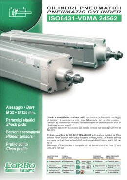
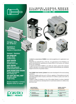
9
9.01.00
CILINDRI IDRAULICI PER MEDIA PRESSIONE – serie 1M
Hydraulic cylinders for middle pressure – 1M series
SERIE 1M
(70 bar nominale)
Costruzione di precisione a tiranti con testate quadre
Precision construction with tie rod and square heads
VARIANTE BOCCOLA / Bushing variation
VARIANTE PISTONE / Piston variation
COMPONENTI / Components
1 -
Stelo in acciaio cromato di alta qualità
Cromate steel rod of high quality
2 -
Piastra di contenimento in acciaio
Containment plate on steel
10 -
Guarnizione balsele
Rod seal
3 -
Boccola in bronzo
Bronze bushing
11 -
Spillo ammortizzamento completo di OR-ing
Damper metering with OR-ing
4 -
Testata anteriore in acciaio
Steel front head
12 -
Guarnizione pistone MU-P
MU-P piston gasket
5 -
Bussola ammortizzamento in ghisa sferoidale
Spheroidal damper bush
13 -
Tirante in acciaio alta resistenza
Steel tie rod with high resistance
6 -
Pistone in ghisa sferoidale
Spheroidal piston
14 -
Guarnizione OR-ing testata-camicia
OR-ing gasket head-cylinder liner
7 -
Camicia in acciaio levigato
Smooth steel cylinder liner
15 -
Valvola partenza rapida con Or-ing e sfera
Jump start valve with OR-ing and ball
8 -
Testata posteriore in acciaio
Steel back head
9-
Guarnizione raschiatore
Wiper
Per versioni per alta velocità di scorrimento e minimo attrito o per funzionamento ad alte temperature , è consigliabile adoperare le varianti per
boccola (23) e per pistone (26).
For version with high speed of slide and minimum friction or for working on high temperature, it is advisable use bushing variation (23) and
piston variation (26).
9.01.01
CILINDRI IDRAULICI PER MEDIA PRESSIONE – serie 1M
Hydraulic cylinders for middle pressure – 1M series
COMPOSIZIONE SIGLA / Composition of mark
Ad ogni cilindro idraulico di nostra costruzione viene assegnato un numero di matricola
che identifica il lotto, l’anno di costruzione e la norma di riferimento seguita dalla sigla.
For any hydraulic cylinder we estabilish a matricolation number that determines the lot
of cylinder, the year of construction and the reference rules before the mark.
ESEMPIO SIGLA / Example mark
1M
D
80/50
M
CP
60
FAP
S
Serie costruttiva 1M per media pressione 70 bar
1M series for 70 bar middle pressure
D serve solo per versione a stelo passante
D is used only for through rod
Alesaggio / ø stelo
Bore / ø rod
Versione a stelo maschio M - Versione a stelo femmina F
M male rod - F Female rod
Tipo di fissaggio (vedi schemi)
Fastener (look scheme)
Corsa (espressa in mm)
Stroke (on mm)
Ammortizzatori
Dumper
NF
FA
FP
FAP
non ammortizzato / not dumper
amm. solo anteriore / front only
amm. solo posteriore / back only
anteriore + posteriore / front and back
S solo per esecuzioni speciali a disegno
S only for special draws
CARATTERISTICHE TECNICHE / Technical features
- Pressione nominale:
70 bar
- Nominal working pressure:
70 bar
- Temperatura normale di esercizio:
-12°C ÷ +90°C
- Working pressure:
-12°C ÷ +90°C
- Norme costruttive di riferimento:
N.F.P.A ed JIC
- Construction pattern:
N.F.P.A ed JIC
- Fissaggi standard:
16 tipi (vedi schemi)
- Standard fastening:
16 type (look scheme)
- Fluido standard:
olio idraulico
- Standard fluid:
Hydraulic oil
- Alesaggi dei cilindri:
dal ø 25 al ø 150
- Cylinder bores:
from ø 25 to ø 150
- Diametri degli steli:
dal ø 12 al ø 100
- Rod diameter:
from ø 12 to ø 100
- Guarnizioni a perfetta tenuta
- Perfect seals
- Ammortizzatori extra-lunghi precisi e sensibili nella regolazione
- Precise and sensitive extra-long dumper for regulator
- Per gli alesaggi 40/25 – 50/32 – 63/45 (con il diametro stelo
maggiore), l’ammortizzamento anteriore è senza regolazione.
- Per l’alesaggio 25 l’ammortizzamento è senza regolazione sia
dal lato anteriore, sia dal lato posteriore.
- Compatibilmente alla forma costruttiva, lo spillo che serve per la
regolazione dell’ammortizzamento viene montato in posizione 4,
mentre la vite che serve come valvola di ritegno, viene montata in
posizione 2.
Le due sedi sono generalmente contrapposte ed intercambiabili.
- Il numero di matricola è indispensabile qualora il cilindro venga
costruito in esecuzione speciale.
- Ripetendo un ordine di cilindri, è sufficiente indicare
solamente il numero di matricola assegnato.
- For 40/25 – 50/32 – 63/45 bores (with bigger rod diameter) the front
dumper is without regulation.
- For 25 bores the dumper is without regulation
both front and back
- Generally dumper metering is mounted on 4 position, instead the
screw that is used like jump start valve is mounted on 2 position.
Generally two seats are contrasting and interchangeable.
- The matricolation number is important when the cylinder is an
special esecution.
- Repeating an order of cylinders, it is enough to say only the
matricolation number
9.01.02
9
CILINDRI IDRAULICI PER MEDIA PRESSIONE – serie 1M
Hydraulic cylinders for middle pressure – 1M series
CILINDRO BASE tipo SF – Basic cylinder SF type
CILINDRO BASE A STELO PASSANTE tipo D – Through rod basic cylinder D type
ESTREMITA’ STELI – Rod
Esecuzione con filetto maschio
M
9.01.03
Esecution with male rod
M
Esecuzione con filetto femmina
F
Esecution with female rod
F
CILINDRI IDRAULICI PER MEDIA PRESSIONE – serie 1M
Hydraulic cylinders for middle pressure – 1M series
FLANGIA RETTANGOLARE
FRA
FRP
anteriore
posteriore
FLANGIA QUADRA
FQA
FQP
anteriore
ATTACCHI A PIEDINI
AL
AC
posteriore
laterali al cilindro
in asse al cilindro
FRA
FRP
front flange
rear flange
Square flange
FQA
FQP
front flange
Wide feet
AL
AC
Rectangular flange
rear flange
lateral
on axis
9
9.01.04
CILINDRI IDRAULICI PER MEDIA PRESSIONE – serie 1M
Hydraulic cylinders for middle pressure – 1M series
ATTACCHI A PIEDINI
AF
frontali al cilindro
FORI FILETTATI SULLE TESTATE
CERNIERA POSTERIORE
9.01.05
CP
FF
Wide feet
AF
frontal
Threaded hole
FF
Rear hinge
CP
CILINDRI IDRAULICI PER MEDIA PRESSIONE – serie 1M
Hydraulic cylinders for middle pressure – 1M series
PERNI
PA
PP
PERNI INTERMEDI
PI
TIRANTI
TA
TP
TT
su testata anteriore
su testata posteriore
Pivot
PA
PP
Middling pivot
sporgenti lato anteriore
sporgenti lato posteriore
sporgenti da entrambi i lati
Ties
TA
TP
TT
front
rear
PI
projecting front
projecting rear
projecting front+rear
9
9.01.06
CILINDRI IDRAULICI PER MEDIA PRESSIONE – serie 1M
Hydraulic cylinders for middle pressure – 1M series
FORCELLA FEMMINA PER STELO - Female fork for rod
Cod.
Er
CB
CW
A
CE
CD
+ 0,1
+ 0,05
CW
KK
A
CB
CE
CW
Carico
max
Er
CFS M 8 x 1,25
20,6
8,8
7,9
57,2
5,2
7,5
Kg.
1000
CFS M 10 x 1,5
19,1
19,8
12,7
38,1
12,7
12,7
Kg.
1500
CFS M 20 x 1,5
28,9
32,6
19,05
54
15,9
19,1
Kg.
4000
CFS M 26 x 1,5
41,3
38,9
25,4
74,6
19,1
25,4
Kg.
7500
CFS M 33 x 2
50,8
51,6
34,93
95,3
25,4
34,9
Kg. 12500
CFS M 39 x 2
57,2
44,5
Kg. 15000
CFS M 48 x 2
76,2
CFS M 64 x 2
44,45 114,3
64,7
CFS M 58 x 2
KK
CD
77,4
88.9
CFS M 76 x 2
102,8
31,8
50,8
139,7
50,8
Kg. 30000
63,5
165,1
63,5
Kg. 45000
76,2
171,5
69,9
Kg. 50000
88,9
196,9
88,9
Kg. 90000
38,1
50,8
PERNO PER FORCELLA FEMMINA - Fork pivot
Cod.
PF08 PF10 PF20 PF26 PF33 PF39 PF48 PF58 PF64 PF76
CD
7,9
12,7
19,05
25,4
34,93
CG
28
54
75
90
117
44,45
50,8
63,5
142
76,2
88,9
168
220
CERNIERA MASCHIO PER STELO - Male fork for rod
Cod.
KK
A
B
50,6
25
19,1
12,7
CMS M 20 x 1,5
72,4
40
31,8
19,05
52,4
28,5
CMS M 26 x 1,5
96,4
50
38,1
25,4
71,4
41
CMS M 33 x 2
122,3
70
50,8
34,93
87,3
51
CMS M 39 x 2
146,6
90
44,45
101,6
57
CMS M 48 x 2
177
100
50,8
127
76
CMS M 58 x 2
212,6
130
63,5
147,6
CMS M 64 x 2
230,6
150
76,2
155,6
CMS M 76 x 2
283,7
180
88,9
193,7
CMS M 8 x 1,25
CMS M 10 x 1,5
EM
CK H9
11,1
11,1
63,5
76,2
101,6
CA
AW
16
38,1
19
89
101,5
PERNO PER CERNIERA POSTERIORE CP - Pivot for CP rear hinge
Cod.
Alesaggio
9.01.07
PCP 1M 456
40
50
63
PCP 1M 811
80
100
125
PCP 1M 150
150
CD
12,72
19,05
25,4
CG
52,5
72,5
84,5
Carico max
Kg. 1500
Kg. 4000
Kg. 7500
CILINDRI IDRAULICI PER MEDIA PRESSIONE – serie 1M
Hydraulic cylinders for middle pressure – 1M series
QUOTE FISSE COMUNI / Common fixed dimensions
Alesaggio
25
40
50
63
80
100
125
150
E
38,1
50,8
63,5
76,2
95,25
114,30
139,70
165,10
F
9,5
16
19
G
38
44,5
51
J
25,5
31,7
38
K
7
9
11
13
14
L
12,7
18,9
31,7
38,2
M
24
31,5
51
63,5
P
54
R
27,5
AA
27
AC
± 0,05
57,2
36
60,3
46,5
66,7
55,5
70
84,5
33,5
73,1
79,4
104
124
44,5
18,87
25,22
BB
19
25,5
28,5
BD
---
32
38
BL
27,5
37
CA
11,1 *
45,2
64,5
76,9
CB
---
19,8
32,5
38,9
11,2
12,72
19,08
25,43
CD
+ 0,03
DD
31,57
37,92
56,97
69,67
35
82,37
46
51
47,5
M6 x 1
47,45
57
58
71,5
85
M8 x 1,25
M10 x 1,5
64
104,5
126
M12 x 1,75
M14 x 2
39,7
38
EA
---
EB
---
EE Gas
1/4"
EL
---
19
23,8
27
22,2
25,4
27
25,4
ET
---
14
19
22
25
32
38
40
FB
6,5
8,5
LB
98,3
101,6
104,8
123,8
130,2
146
LD
120,7
123,8
127
152,4
158,8
178
M10 x 1,5
M12 x 1,75
M16 x 2
M20 x 2,5
MR
12,7
NT
M5 x 0,8
SB
6,5
SE
---
SN
54
SS
ST
TD
+0
- 0,03
25,4
31,7
35
31,7
35
8,5
10,5
14,5
3/8“
1/2"
10,5
12,5
14,5
14,3
M6 x 1
M8 x 1,25
27
10,5
139,6
149,2
57,2
73
8
3/4"
28,6
14,5
158,8
168,2
20,5
184,2
197
60,3
66,7
73,1
79,3
76,2
82,5
79,4
92
11
174,6
18
19,05
24
25,4
34,92
TF
51
70
86
98,5
119
138
168,5
193,5
TM
---
63,5
76,2
88,9
114,3
133,4
158,8
193,7
TN
13,5
15,5
22
31
38
52
66
80
TY
---
63,5
76
89
108
127
152,5
178
TK
6,5
24
28
TS
54
70
82,5
95
120,5
139,5
174,5
200
UF
63,5
85,7
104,8
117,5
139,7
158,7
193,7
219
UM
---
114,3
127
139,7
165,1
184,2
210
263,6
US
70
91
103,5
116
145
164
209,5
235
UT
76
102
114,5
127
146
165
190,5
235
9,5
15
19
* costa singola / single tongue
9.01.08
9
CILINDRI IDRAULICI PER MEDIA PRESSIONE – serie 1M
Hydraulic cylinders for middle pressure – 1M series
QUOTE VARIANTI in relazione al diametro dello stelo
VARIATION DIMENSIONS in relation to rod’s diameter
Alesaggio
Bore
25
40
50
63
80
Ø stelo
Ø rod
KK
A
B
12
M8 x 1,25
16
25,4
+0
- 0,05
C
D
V
W
Y
Z
6,4
15,9
49,2
114,3
10
9,5
16
M10 x 1,5
19
27
16
M10 x 1,5
19
28,5
9,5
13
6,4
15,9
49,2
117,5
25
M20 x 1,5
28,5
38,1
12,7
22
12,7
25,4
58,7
127
16
M10 x 1,5
19
28,5
9,5
13
6,4
15,9
49,2
117,5
25
M20 x 1,5
28,5
38,1
12,7
22
12,7
25,4
58,7
127
32
M26 x 1,5
41
50,8
15,9
29
15,9
31,8
65,1
133,4
16
M10 x 1,5
19
28,5
9,5
13
6,4
15,9
49,2
120,7
25
M20 x 1,5
28,5
38,1
12,7
22
12,7
25,4
58,7
130,2
32
M26 x 1,5
41
50,8
15,9
29
15,9
31,8
65,1
136,5
45
M33 x2
51
60,3
19,1
36
19
38,1
71,4
142,9
25
M20 x 1,5
28,5
38,1
12,7
22
6,4
19,1
61,9
142,9
32
M26 x 1,5
41
50,8
15,9
29
9,5
25,4
68,3
149,3
45
M33 x 2
51
60,3
19,1
36
31,8
74,6
155,6
34,9
77,8
158,8
13
12,7
100
50
M39 x 2
57
66,6
22,2
44
25
M20 x 1,5
28,5
38,1
12,7
22
6,4
19,1
61,9
142,9
32
M26 x 1,5
41
50,8
15,9
29
9,5
25,4
68,3
149,3
45
M33 x 2
51
60,3
19,1
36
31,8
74,6
155,6
34,9
77,8
158,8
12,7
50
M39 x 2
57
66,6
22,2
44
63
M48 x 2
76
79,3
25,4
55
15,9
41,3
84,1
165,2
25
M20 x 1,5
28,5
38,1
12,7
22
6,4
19,1
61,9
149,3
32
M26 x 1,5
41
50,8
15,9
29
9,5
25,4
68,3
155,6
45
M33 x 2
51
60,3
19,1
36
31,8
74,6
161,9
34,9
77,8
165,1
15,9
41,3
84,1
171,5
6,4
22,2
71,4
168,2
28,6
77,8
174,6
31,8
81
177,7
38,1
87,3
184,1
12,7
125
50
M39 x 2
57
66,6
63
M48 x 2
76
79,3
70
M58 x 2
89
95,2
90
M64 x 2
89
107,9
32
M26 x 1,5
41
50,8
15,9
29
45
M33 x 2
51
60,3
19,1
36
22,2
44
55
25,4
65
75
9,5
150
50
M39 x 2
57
66,6
63
M48 x 2
76
79,3
70
M58 x 2
89
95,2
22,2
44
55
65
25,4
9.01.09
12,7
90
M64 x 2
89
107,9
75
100
M76 x 2
101,5
120,6
85
CILINDRI IDRAULICI PER MEDIA PRESSIONE – serie 1M
Hydraulic cylinders for middle pressure – 1M series
QUOTE VARIANTI in relazione al diametro dello stelo
VARIATION DIMENSIONS in relation to rod’s diameter
Alesaggio
Bore
25
40
50
63
80
100
125
Ø stelo
Ø rod
EC
12
---
16
---
16
WA
ZF
ZL
ZM
XC
XG
XS
XT
101,6
123,8
136,6
152,4
127
44,4
33,3
49,2
136,5
104,8
127
139,7
155,6
136,4
44,4
34,9
49,2
25
146
114,3
136,5
149,2
174,6
145,9
54
44,5
58,7
16
141,3
104,8
127
139,7
155,6
136,4
44,4
34,9
49,2
25
150,8
114,3
136,5
149,2
174,6
145,9
54
44,5
58,7
32
157,2
120,6
142,9
155,6
187,3
152,3
60,3
50,8
65,1
16
147,7
107,9
130,2
142,9
158,8
139,6
44,4
34,9
49,2
25
157,1
117,5
139,6
152,4
177,8
149
54
44,5
58,7
32
163,5
123,8
146
158,8
190,6
155,4
60,3
50,8
65,1
45
169,9
130,2
152,4
165,1
203,2
161,8
66,7
57,1
71,4
25
165,1
127
158,8
171,5
190,6
174,6
57,1
47,7
61,9
32
171,5
133,3
165,2
177,8
203,2
181
63,5
54
68,3
45
177,8
139,7
171,5
184,2
216
187,3
69,8
60,4
74,6
50
181
142,9
174,7
187,3
222,3
190,5
73
63,5
77,8
25
168,3
127
158,8
171,5
190,5
174,6
57,1
47,7
61,9
32
174,7
133,3
165,2
177,8
203,2
181
63,5
54
68,3
45
181
139,7
171,5
184,2
216
187,3
69,8
60,4
74,6
50
184,2
142,9
174,7
187,3
222,3
190,5
73
63,5
77,8
63
190,6
149,2
181,1
193,7
235
196,9
79,4
69,9
84,1
25
176,2
133,3
165,1
177,9
196,9
181
57,1
52,4
61,9
32
182,6
139,7
171,5
184,2
209,6
187,3
63,5
58,7
68,3
45
188,9
146
177,8
190,6
222,3
193,6
69,8
65
74,6
50
192,1
149,2
181
193,7
228,6
196,8
73
68,2
77,8
198,5
155,6
187,4
200,1
241,3
203,2
79,4
74,6
84,1
32
193,6
149,2
187,2
200,2
222,3
206,4
66,7
58,8
71,4
45
200
155,6
193,6
206,6
235,2
212,8
73
65
77,8
50
203,1
158,7
196,7
209,8
241,6
215,9
76,2
68,2
81
209,5
165,1
203,1
216,1
254,2
222,3
82,5
74,6
87,3
63
70
90
150
63
70
90
100
9.01.10
9
CILINDRI IDRAULICI PER ALTA PRESSIONE – serie 1P
Hydraulic cylinders for high pressure – 1P series
SERIE PESANTE 1P
(210 bar nominale)
Costruzione di precisione a tiranti con testate quadre
Precision construction with tie rod and square heads
VARIANTE BOCCOLA / Bushing variation
VARIANTE PISTONE / Piston variation
COMPONENTI / Components
1 -
Stelo in acciaio cromato di alta qualità
Cromate steel rod of high quality
2 -
Piastra di contenimento in acciaio
Containment plate on steel
10 -
Guarnizione balsele
Rod seal
3 -
Boccola in bronzo
Bronze bushing
11 -
Spillo ammortizzamento completo di OR-ing
Damper metering with OR-ing
4 -
Testata anteriore in acciaio
Steel front head
12 -
Guarnizione pistone DBM
DBM piston gasket
5 -
Bussola ammortizzamento in ghisa sferoidale
Spheroidal damper bush
13 -
Tirante in acciaio alta resistenza
Steel tie rod with high resistance
6 -
Pistone in acciaio
Steel piston
14 -
Guarnizione OR-ing testata-camicia + antiestrusore
OR-ing gasket head-cylinder liner
7 -
Camicia in acciaio levigato
Smooth steel cylinder liner
15 -
Valvola partenza rapida con Or-ing e sfera
Jump start valve with OR-ing and ball
8 -
Testata posteriore in acciaio
Steel back head
9-
Guarnizione raschiatore
Wiper
Per versioni per alta velocità di scorrimento e minimo attrito o per funzionamento ad alte temperature , è consigliabile adoperare le varianti per
boccola (23) e per pistone (26).
For version with high speed of slide and minimum friction or for working on high temperature, it is advisable use bushing variation (23) and
piston variation (26).
9.01.11
CILINDRI IDRAULICI PER ALTA PRESSIONE – serie 1P
Hydraulic cylinders for high pressure – 1P series
COMPOSIZIONE SIGLA / Composition of mark
Ad ogni cilindro idraulico di nostra costruzione viene assegnato un numero di matricola
che identifica il lotto, l’anno di costruzione e la norma di riferimento seguita dalla sigla.
For any hydraulic cylinder we estabilish a matricolation number that determines the lot
of cylinder, the year of construction and the reference rules before the mark.
ESEMPIO SIGLA / Example mark
1P
D
80/50
M
CP
60
FAP
S
Serie costruttiva 1P pesante per alte pressioni 210 bar
1P series for 210 bar high pressure
D serve solo per versione a stelo passante
D is used only for through rod
Alesaggio / ø stelo
Bore / ø rod
Versione a stelo maschio M - Versione a stelo femmina F
M male rod - F Female rod
Tipo di fissaggio (vedi schemi)
Fastener (look scheme)
Corsa (espressa in mm)
Stroke (on mm)
Ammortizzatori
Dumper
NF
FA
FP
FAP
non ammortizzato / not dumper
amm. solo anteriore / front only
amm. solo posteriore / back only
anteriore + posteriore / front and back
S solo per esecuzioni speciali a disegno
S only for special draws
CARATTERISTICHE TECNICHE / Technical features
- Pressione nominale:
210 bar (nominale)
- Nominal working pressure:
210 bar (nominale)
- Temperatura normale di esercizio:
-12°C ÷ +90°C
- Working pressure:
-12°C ÷ +90°C
- Norme costruttive di riferimento:
N.F.P.A ed JIC
- Construction pattern:
N.F.P.A ed JIC
- Fissaggi standard:
16 tipi (vedi schemi)
- Standard fastening:
16 type (look scheme)
- Fluido standard:
olio idraulico
- Standard fluid:
Hydraulic oil
- Alesaggi dei cilindri:
dal ø 40 al ø 200
- Cylinder bores:
from ø 40 to ø 200
- Diametri degli steli:
dal ø 16 al ø 140
- Rod diameter:
from ø 16 to ø 140
- Guarnizioni a perfetta tenuta
- Perfect seals
- Ammortizzatori extra-lunghi precisi e sensibili nella regolazione
- Precise and sensitive extra-long dumper for regulator
- Per gli alesaggi 40/25 – 50/32 – 63/45 (con il diametro stelo
maggiore), l’ammortizzamento anteriore è senza regolazione.
- Compatibilmente alla forma costruttiva, lo spillo che serve per la
regolazione dell’ammortizzamento viene montato in posizione 4,
mentre la vite che serve come valvola di ritegno, viene montata in
posizione 2.
Le due sedi sono generalmente contrapposte ed intercambiabili.
- Il numero di matricola è indispensabile qualora il cilindro venga
costruito in esecuzione speciale.
- Ripetendo un ordine di cilindri, è sufficiente indicare
solamente il numero di matricola assegnato.
- For 40/25 – 50/32 – 63/45 bores (with bigger rod diameter) the front
dumper is without regulation.
- Generally dumper metering is mounted on 4 position, instead the
screw that is used like jump start valve is mounted on 2 position.
Generally two seats are contrasting and interchangeable.
- The matricolation number is important when the cylinder is an
special esecution.
- Repeating an order of cylinders, it is enough to say only the
matricolation number
9.01.12
9
CILINDRI IDRAULICI PER ALTA PRESSIONE – serie 1P
Hydraulic cylinders for high pressure – 1P series
CILINDRO BASE tipo SF – Basic cylinder SF type
CILINDRO BASE A STELO PASSANTE tipo D – Through rod basic cylinder D type
ESTREMITA’ STELI – Rod
Esecuzione con filetto maschio
M
9.01.13
Esecution with male rod
M
Esecuzione con filetto femmina
F
Esecution with female rod
F
CILINDRI IDRAULICI PER ALTA PRESSIONE – serie 1P
Hydraulic cylinders for high pressure – 1P series
FLANGIA RETTANGOLARE
FRA
FRP
anteriore
posteriore
FLANGIA QUADRA
FQA
FQP
anteriore
ATTACCHI A PIEDINI
AL
AC
posteriore
laterali al cilindro
in asse al cilindro
FRA
FRP
front flange
rear flange
Square flange
FQA
FQP
rear flange
Wide feet
AL
AC
Rectangular flange
front flange
lateral
on axis
9
9.01.14
CILINDRI IDRAULICI PER ALTA PRESSIONE – serie 1P
Hydraulic cylinders for high pressure – 1P series
ATTACCHI A PIEDINI
AF
frontali al cilindro
FORI FILETTATI SULLE TESTATE
CERNIERA POSTERIORE
9.01.15
CP
FF
Wide feet
AF
frontal
Threaded hole
FF
Rear hinge
CP
CILINDRI IDRAULICI PER ALTA PRESSIONE – serie 1P
Hydraulic cylinders for high pressure – 1P series
PERNI
PA
PP
PERNI INTERMEDI
PI
TIRANTI
TA
TP
TT
su testata anteriore
su testata posteriore
Pivot
PA
PP
Middling pivot
sporgenti lato anteriore
sporgenti lato posteriore
sporgenti da entrambi i lati
Ties
TA
TP
TT
front
rear
PI
projecting front
projecting rear
projecting front+rear
9
9.01.16
CILINDRI IDRAULICI PER ALTA PRESSIONE – serie 1P
Hydraulic cylinders for high pressure – 1P series
FORCELLA FEMMINA PER STELO - Female fork for rod
Cod.
Er
CB
CW
A
CB
CFS M 10 x 1,5
19,1
CFS M 20 x 1,5
28,9
CFS M 26 x 1,5
CW
Carico
max
CD
CE
19,8
12,7
38,1
12,7
12,7
Kg.
1500
32,6
19,05
54
15,9
19,1
Kg.
4000
41,3
38,9
25,4
74,6
19,1
25,4
Kg.
7500
CFS M 33 x 2
50,8
51,6
34,93
95,3
25,4
34,9
Kg. 12500
CFS M 39 x 2
57,2
44,5
Kg. 15000
CFS M 48 x 2
76,2
50,8
Kg. 30000
63,5
Kg. 45000
69,9
Kg. 50000
Kg. 90000
44,45 114,3
64,7
Er
31,8
50,8
139,7
63,5
165,1
76,2
171,5
88,9
196,9
50,8
88,9
101,6 223,8
57,2
101,6
A
CE
CD
+ 0,1
+ 0,05
CW
KK
CFS M 58 x 2
CFS M 64 x 2
88.9
CFS M 76 x 2
KK
77,4
102,8
CFS M 90 x 2
CFS M 100 x 2
101,6
116
38,1
Kg. 110000
Kg. 120000
PERNO PER FORCELLA FEMMINA - Fork pivot
Cod.
PF10 PF20 PF26 PF33 PF39 PF48 PF58 PF64 PF76 PF90
CD
12,7
19,05
25,4
34,93
CG
54
75
90
117
44,45
50,8
63,5
142
76,2
168
88,9
101.6
220
245
CERNIERA MASCHIO PER STELO - Male fork for rod
Cod.
KK
A
B
EM
CK H9
CA
AW
CMS M 10 x 1,5
50,6
25
19,1
12,7
38,1
19
CMS M 20 x 1,5
72,4
40
31,8
19,05
52,4
28,5
CMS M 26 x 1,5
96,4
50
38,1
25,4
71,4
41
CMS M 33 x 2
122,3
70
50,8
34,93
87,3
51
CMS M 39 x 2
146,6
90
44,45
101,6
57
CMS M 48 x 2
177
100
50,8
127
76
CMS M 58 x 2
212,6
130
63,5
147,6
CMS M 64 x 2
230,6
150
76,2
155,6
283,7
180
88,9
193,7
CMS M 76 x 2
CMS M 90 x 2
CMS M 100 x 2
63,5
76,2
101,6
89
101,5
127
331,8
200
114,3
101,6
231,8
140
PERNO PER CERNIERA POSTERIORE CP - Pivot for CP rear hinge
PCP 1P
Cod.
9.01.17
Alesaggio
40
CD
12,72
CG
Carico max
50
63
80
100
125
150
180
200
19,05
25,4
34,95
44,45
50,8
63,5
76,2
55
74
87
112
140
140
Kg.
1500
Kg. 4000
Kg.
7500
Kg.
12500
Kg.
15000
Kg.
30000
165
Kg.
45000
Kg.
50000
CILINDRI IDRAULICI PER ALTA PRESSIONE – serie 1P
Hydraulic cylinders for high pressure – 1P series
QUOTE FISSE COMUNI / Common fixed dimensions
Alesaggio
40
50
63
80
100
125
150
180
200
E
63,5
76,2
88,9
114,3
127
165,1
190,5
215,9
241,3
F
9,5
16
19
22,2
25,4
G
44,5
51
57
70
76
J
38
44,5
57
70
76
K
11
13
22
27
30
33
L
19
31,8
38
54
57,2
63,5
76,2
82,5
M
32
51
63,5
89
101,5
114,5
139,5
152,5
76,2
88,9
95,3
108
123,8
136,5
155,6
65
82,5
97
125,5
145,5
167
190,5
P
73
R
41,5
52
AA
33,5
44,5
31,57
37,92
AC
± 0,05
17
57
44,25
BB
35
46
BD
32
38
BL
41,5
CA
44,4
CB
19
73
56,97
90
63,32
58,5
82,37
95,07
107,77
120,47
81
92
105
114,5
51
63,5
76,2
101,6
127
152,4
31,8
38,1
50,8
63,5
76,2
12,72
19,08
25,43
34,95
DD
M10 x1,5
M12 x 1,75
EA
31,7
36,5
EB
10,5
12,5
EE Gas
14,5
125,6
145,8
89
97,6
CD
65
76
83
+ 0,03
52,8
108
168
191,5
44,48
50,83
63,53
76,23
M16 x 2
M22 x 2,5
M27 x 3
M30 x 2
M32 x 2
44,5
57
65
71,5
79,5
16,5
23
27,5
30,5
33,5
1"
1 1/4"
1 1/2"
EL
22,2
1/2"
23,8
28,6
3/4"
38,1
42,9
46
50,8
ET
22
25
30
38
44
FB
10,5
24,5
27,5
31
34
LB
127
133,4
136,5
159
168,5
181
212,5
241,5
266,3
LD
142,9
155,9
159,1
184,5
197,2
209,9
237,8
267
291,7
28,6
44,4
54
63,5
M16 x 2
M20 x 2,5
14,5
MR
14,3
NT
M10 x 1,5
M12 x 1,75
SB
10,5
14,5
SE
171,4
SN
SS
ST
TD
+0
- 0,03
18,5
27
23
181
73,1
98,5
92,1
13
19
25,4
47,6
50
83
M24 x 3
M30 x 3,5
M42 x 4,5
27,5
33,5
40
184,1
216,2
225,7
257,2
298,3
333,5
367,9
76,2
88,9
95,2
107,9
130,2
142,9
168,3
85,7
104,7
101,6
114,3
130,1
146,1
171,5
24
33
34,92
38
44,45
44
50,80
63,5
76,2
TF
87,5
105
117,5
149
162
208
239,5
270
300
TM
76,2
88,9
101,6
127
139,7
177,8
215,9
247,7
279,4
TN
18
23,8
32
38,1
52,4
74,6
84,1
90
105
TY
70
82,5
95
120,5
133,5
171,5
197
222
248
28
40
TS
82,5
101,6
123,8
149,2
171,5
209,5
247,6
285,7
311
UF
108
130
142,7
180,8
193,5
247,6
285,7
320,7
355,6
UM
127
158,8
171,5
215,9
228,6
266,7
317,5
374,7
431,8
US
103,5
126
159
184
217
255
305
355,5
381
UT
114,5
146
159
203
216
254
292
343
393,5
UW
101,5
121
133,5
171,5
184
228,5
260,5
292
324
TK
15
23
50
9.01.18
9
CILINDRI IDRAULICI PER ALTA PRESSIONE – serie 1P
Hydraulic cylinders for high pressure – 1P series
QUOTE VARIANTI in relazione al diametro dello stelo
VARIATION DIMENSIONS in relation to rod’s diameter
Alesaggio
Bore
40
50
63
80
100
125
150
180
200
9.01.19
Ø stelo
Ø rod
KK
A
B
16
M10 x 1,5
19
25
M20 x 1,5
25
+0
- 0,05
C
D
V
W
Y
Z
28,5
9,5
13
6,4
15,9
50,8
142,9
28,5
38,1
12,7
22
12,7
25,4
60,3
152,4
M20 x 1,5
28,5
38,1
12,7
22
6,4
19,1
60,3
152,5
32
M26 x 1,5
41
50,8
15,9
29
9,5
25,4
66,7
158,8
25
M20 x 1,5
28,5
38,1
12,7
22
6,4
19,1
60,3
155,6
32
M26 x 1,5
41
50,8
15,9
29
9,5
25,4
66,7
161,9
45
M33 x2
51
60,3
19,1
36
12,7
31,8
73
168,3
32
M26 x 1,5
41
50,8
15,9
29
6,3
22,2
69,9
181,2
45
M33 x 2
51
60,3
19,1
36
9,5
28,6
76,2
187,6
50
M39 x 2
57
66,6
22,2
44
9,6
31,8
79,4
190,8
45
M33 x 2
51
60,3
19,1
36
6,3
25,4
76,2
193,9
50
M39 x 2
57
66,6
22,2
44
6,4
28,6
79,4
197,1
63
M48 x 2
76
79,3
25,4
55
9,5
34,9
85,7
203,4
50
M39 x 2
57
66,6
22,2
44
6,4
28,6
79,4
209,6
63
M48 x 2
76
79,3
70
M58 x 2
89
95,2
9,5
34,9
85,7
215,9
90
M64 x 2
89
107,9
75
63
M48 x 2
76
79,3
55
70
M58 x 2
89
95,2
6,4
31,8
88,9
244,3
6,4
31,8
96,8
273,3
6,4
31,8
100
298,1
55
25,4
65
65
25,4
90
M64 x 2
89
107,9
75
100
M76 x 2
101,5
120,6
85
70
M58 x 2
89
95,2
65
90
M64 x 2
89
107,9
75
25,4
100
M76 x 2
101,5
120,6
85
125
M90 x 2
127
146
110
90
M64 x 2
89
107,9
75
100
M76 x 2
101,5
120,6
85
25,4
125
M90 x 2
127
146
110
140
M100 x 2
140
158,7
120
CILINDRI IDRAULICI PER ALTA PRESSIONE – serie 1P
Hydraulic cylinders for high pressure – 1P series
QUOTE VARIANTI in relazione al diametro dello stelo
VARIATION DIMENSIONS in relation to rod’s diameter
Alesaggio
Bore
40
50
63
80
100
125
Ø stelo
Ø rod
EC
WA
ZF
ZL
ZM
XC
XG
XS
XT
16
165,1
123,7
152,4
158,8
174,7
161,9
47,6
34,9
50,8
25
174,6
133,3
161,9
168,3
193,7
171,4
57,2
44,5
60,4
25
176,3
133,3
168,5
174,9
194
184,3
57,2
47,6
60,4
32
182,6
139,7
174,8
181,3
206,7
190,6
63,6
54
66,7
25
179,4
136,5
171,6
178,1
197,2
187,4
57,2
52,4
60,4
32
185,7
142,9
177,9
184,3
209,7
193,7
63,6
58,7
66,7
45
192,1
149,2
184,3
190,7
222,5
200,1
69,9
65,1
73
32
209,8
158,7
200,2
206,5
228,7
219,2
66,7
58,7
69,8
45
216,2
165,1
206,6
212,9
241,5
225,6
73
65,1
76,2
50
219,4
168,2
209,8
216
247,8
228,8
76,1
68,2
79,4
45
222,5
171,6
216,1
222,6
248
247,9
73,2
70
76,2
50
225,7
174,6
219,3
225,6
254,2
251,1
76,2
73
79,4
63
232
180,9
225,6
231,9
266,8
257,4
85,5
79,3
85,7
50
247,7
187,3
231,8
238,2
266,8
266,8
76,2
73
79,4
254
193,6
238,1
244
279,5
273,1
82,5
79,3
85,7
287,2
217,7
269,7
269,8
301,6
307,8
85,7
85,7
88,9
319,3
238,1
298,7
298,7
330,5
349,5
92,1
92,1
96,9
348,9
260,4
323,5
323,7
355,5
380,6
95,2
92,1
100
63
70
90
63
150
70
90
100
70
180
90
100
125
90
200
100
125
140
9.01.20
9
ACCESSORI PER CILINDRI IDRAULICI – serie 1M / 1P
Accessories for hydraulic cylinders – 1M / 1P series
TERMINALE A SNODO RILUBRIFICABILE PER STELI
Ball-joint ends with grease nipple for rod
Cod.
*
*
*
*
*
*
*
*
*
KK
d
S
I
Lf
d1
d2
d3
d4
S1
L
L1
CST M 12 x 1,5
12
12
38
17
32
32
16
15,5
10,5
54
14
CST M 20 x 1,5
25
25
65
29
58
54
30
30,5
21
96
27
CST M 27 x 2
32
32
80
37
70
66
38
38
27
118
32
CST M 33 x 2
40
40
97
46
89
80
47
46
32
145,5
41
CST M 42 x 2
50
50
120
57
108
96
58
57
40
179
50
CST M 48 x 2
63
63
140
64
132
114
70
71,5
52
211
62
CST M 56 x 2
70
70
160
76
155
135
80
79
57
245
70
CST M 64 x 3
80
80
180
86
168
148
90
91
66
270
78
CST M 72 x 3
90
90
195
91
185
160
100
99
72
296
85
CST M 80 x 3
100
100
210
96
210
178
110
113
84
322
98
CST M 90 x 3
110
110
235
101
235
190
125
124
88
364
105
CST M 100 x 3
125
125
260
106
264
200
135
138
103
405
120
MATERIALE :
NORME :
*
MATERIAL :
RULES :
C45
DIN 24330 ISO 6982
Per l’utilizzo di questi snodi, è necessario
eseguire il filetto KK sugli steli dei cilindri
in esecuzione speciale.
*
C45
DIN 24330 ISO 6982
For this type of ball-jointends is necessary
to order cylinders with a special thread KK
PIASTRA CON SNODO SFERICO POSTERIORE RILUBRIFICABILE
Plate with rear ball-joint ends with grease nipple
Cod.
E
BL
DD
F1
d
S
I
d1
d2
S1
L
CS 1P 040
63,5
41,5
M10 x 1,5
12
20
20
50
50
25
19
75
CS 1P 050
76,2
52,8
25
25
61
55
30,5
23
90
M12 x 1,75
16
32
32
81
70
38
27
120
20
40
40
89
100
46
35
140
22
50
50
110
123
57
40
173
CS 1P 063
88,9
65
CS 1P 080
114,3
83
M16 x 2
CS 1P 100
127
97,6
CS 1P 125
165,1
125,6
M22 x 2,5
25
63
63
129
132
71,5
52
205
CS 1P 150
190,5
145,8
M27 x 3
30
70
70
145
164
79
55
230
CS 1P 180
215,9
168
M30 x 2
80
80
176
180
91
60
270
90
90
185
226
99
65
300
35
CS 1P 200
MATERIALE :
NORME :
241,3
191,5
M32 x 2
FE510
Snodo a norme CETOP
Questo fissaggio è consigliabile adoperarlo in
abbinamento al cilindro serie 1P versione SF
9.01.21
MATERIAL :
RULES :
FE510
CETOP Ball-joint ends
For this type of fixing is necessary to order 1P
cylinders on SF version
Note
Notes
Sono molteplici i fattori che contribuiscono ad un impiego corretto dei There are many elements that help for a right use of hydraulic
cylinder.
cilindri idraulici:
Per determinare l’alesaggio, occorre considerare i seguenti parametri: To determine the bore, it is necessary consider following parameters:
1.
F
F=
S
PxS
strength on Kg.
P = pressione di lavoro (Kg./cm2) / working pressure (Kg./cm2)
S = superficie del cilindro (cm2) / Piston surface (cm2)
(in “tiro” , la S utile risulta essere la differenza con la sezione dello stelo)
(The “pull force” is calculated subtrahend the rod surface)
P
2.
1.
la forza necessaria espressa in Kg.
la pressione di lavoro.
E’ consigliabile adoperare i cilindri della serie 1M ed 1P
entro questi limiti:
2.
MEDIA PRESSIONE 1M - 1M middle pressure
ALTA PRESSIONE 1P - 1P high pressure
(Kg./cm2)
(Kg./cm2)
Pressione
senza colpi
d’ariete
(Kg./cm2)
1M 25/12
130
100
160
1P 40/16
140
210
1M 40/16
105
100
160
1P 50/25
155
210
320
1M 50/16
55
70
120
1P 63/25
130
210
320
1M 63/25
75
70
110
1P 80/32
140
210
320
1M 80/25
60
70
120
1P 100/45
140
210
320
1M 100/32
45
70
90
1P 125/50
130
210
320
1M 125/45
40
58
70
1P 150/63
140
210
320
1M 150/45
35
48
70
1P 180/70
120
210
320
1P 200/90
120
210
320
4:1
Alesaggio / stelo
Bore / rod
3.
Pressione di
esercizio
working pressure.
It would be better to use 1M and 1P cylinders within this
parameters:
il tipo di fissaggio.
Condiziona pesantemente la scelta in base all’applicazione
che può essere:
Alesaggio / stelo
Bore / rod
3.
4:1
Pressione di
esercizio
(Kg./cm2)
(Kg./cm2)
Pressione
senza colpi
d’ariete
(Kg./cm2)
320
type of fastening.
It is influences the choose in according with the use, that
can be:
- fastening with linear trasmission of the strength
(FRA – FRP – FQA – FQP – AC – TA – TP – TT type)
- fastening with strength is trasmission through rotation
(CP – PA – PP – PI type)
- fastening with side trasmission of the strength
(AL – AF – FF type)
- fissaggio con trasmissione lineare della forza
(tipo FRA – FRP – FQA – FQP – AC – TA – TP – TT)
- fissaggio con trasmissione della forza tramite rotazione
(tipo CP – PA – PP – PI)
- fissaggio con trasmissione laterale della forza
(tipo AL – AF – FF)
Per tutte queste applicazioni bisogna valutare attentamente
la “consistenza” del cilindro ed il dimensionamento corretto
dello stelo.
For all this type you must consider the “consistency” of the
cylinder and the right measuring of the rod.
4.
la velocità.
Con guarnizioni standard è di 0,5 mt/sec max
Con guarnizioni su variante boccola (23) e pistone (26) è
possibile ottenere velocità più elevate con minimo attrito.
4.
speed.
With standard gasket it is of 0,5 mt/sec max
With gasket bushing and piston variation it is possible
obtain higher speedy with minimum friction.
5.
la corsa.
Intesa come scelta del diametro di stelo riferendosi in
particolare alle corse lunghe
5.
stroke.
You must choose the rod diametre, expecially for long
stroke.
6.
le forze di accelerazione e decelerazione.
Con carichi pesanti e grandi velocità, è opportuno
prevedere l’uso di ammortizzamenti al fine di aumentare la
durata del cilindro, riducendo il rumore di esercizio ed i
colpi idraulici
6.
acceleration and deceleration strength.
With heavy loads and high temperatures, it would be better
to use dumper to increase the life of the cylinder, and to
reduce the noise during the work
7.
la temperatura di funzionamento.
E’ compresa tra –12°C ÷ +90°C (con guarnizioni standard)
Per temperature superiori, prevedere la variante (23) e (26)
con OR-ing in Viton.
7.
working temperature.
It is included from –12°C to +90°C (with standard gasket).
For higher temperatures it is necessari use the variant (23)
and (26) with Viton OR-ing.
9.01.22
9
Note
Notes
9.01.23
Scaricare