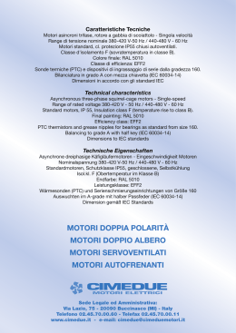
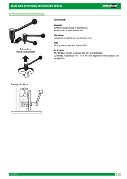
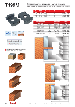
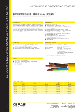
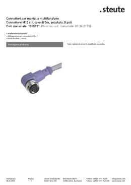
MOTORI ELETTRICI SERVOVENTILATI
FORCEED COOLING ELECTRIC MOTOR
CHIUSI
VENTILAZIONE FORZATA IP 44
VENTILAZIONE FORZATA IP 55
(DA GRANDEZZA 80)
SERIE (SV)
SERIE (SVF)
SERIE (SVFM)
®
LR 91167
81
TOTALY CLOSED
FORCEED VENTILATION IP 44
FORCEED VENTILATION IP 55
(FROM SIZE 80)
SERIES (SV)
SERIES (SVF)
SERIES (SVFM)
B3
IM B3
IM1001
OVERALL DIMENSIONS
DIMENSIONI FORMA COSTRUTTIVA
B3 (CEI 2-14)
FRAME
H
A
B
C
V
L
L2
IM B3 (IEC 34-7 Code I)
G
G1 G2 G3
U
A1 B1
D
E
d
X
R
K
X1 K1 C1
95
10 156 273 243 185 113 145 138 91 135 109 14K6 30 M5 25 26
14 100 Pg11
9
90 140 100 56 115 11 194 352 302 225 135 176 178 109 170 125 24K6 50 M8 32 30
14 134 Pg16
11
63
63 100 80
80
80 125 100 50 115 11 176 315 275 210 129 161 155 103 154 125 19K6 40 M6 29 27
71
90C
90L
IM 1001 (IEC 34-7 Code II)
71 112 90
40
45
95
7
134 243 220 167 102 127 125 80 120 100 11K6 23 M4 23 22
10
91
P
Pg11
H1 h
8
4
5
14 116 Pg13,5 10 6
90 140 125 56 115 11 220 378 328 225 135 176 178 109 170 150 24K6 50 M8 32 30 14 134 Pg16
7
b
t
5
16
8
27
4 12,5
6 21,5
11 7
8
27
112 190 140 70 112 14 267 466 406 267 154 222 223 131 220 175 28K6 60 M8 40 40 18 183 Pg16 15 7
8
31
100
100 160 140 63 115 12 246 423 363 247 146 198 195 120 192 166 28K6 60 M8 38 36 21 154 Pg16 12 7
132C
132 216 140 89 105 13 282 540 460 310 177 271 258 122 256 180 38K6 80 M10 40 43 21 215 Pg21 18 8 10 41
160C
160 254 210 108 150 14 230 750 640 385 234 325 315 182 320 270 42K6 110 M12 58 64 25 325 Pg21 23 8 12 45
112
132M/L
160M/L
8
31
132 216 178 89 105 13 399 579 499 310 177 271 258 122 256 218 38K6 80 M10 40 43 21 215 Pg21 18 8 10 41
160 254 254 108 150 14 230 800 686 385 234 325 315 182 320 310 42K6 110 M12 58 64 25 325 Pg21 23 8 12 45
82
B5
IM B5
IM3001
OVERALL DIMENSIONS
DIMENSIONI FORMA COSTRUTTIVA
B5 (CEI 2-14)
FRAME
P
N
M
Q
R
S
95
11
63
140
115
2,5
95
80
200 130J6 165
2,5
200 130J6 165
3,0
71
90C
90L
100
112
132C
132M/L
160C
160M/L
95J6
160 110J6 130
200 130J6 165
250 180J6 215
250 180J6 215
300 230J6 265
300 230J6 265
350 250J6 300
350 250J6 300
2,5
3,0
3,5
L2
G2
G3
U
F
246
223
102
125
80
9,5
115
11
180
319
279
129
155
103
115
11
224
481
331
135
178
109
115
11
4,0
105
14
5,0
150
5,0
L
137
14
4,0
V
9
115
3,5
IM B5 (IEC 34-7 Code I)
112
105
150
14
14
20
20
161
198
251
270
284
322
230
230
278
357
430
469
542
582
750
800
248
307
370
409
462
502
641
686
83
113
135
146
154
177
177
320
320
138
178
195
223
258
258
315
315
91
109
120
131
112
112
182
182
D
IM 3001 (IEC 34-7 Code II)
E
d
h
b
M5
5
5
11K6
23
M4
11,5
19K6
40
M6
11,5
24K6
50
M8
9,5
11,5
14
14
14
14
18
18
14K6
24K6
28K6
28K6
38K6
38K6
30
50
M8
t
4
12,5
6
6
21,5
7
8
27
4
7
8
16
27
60
M8
7
8
31
80
M10
8
10
41
8
12
60
80
M8
M10
42K6 110 M12
42K6 110 M12
7
8
8
8
10
12
31
41
45
45
B14
IM B14
IM3601
OVERALL DIMENSIONS
DIMENSIONI FORMA COSTRUTTIVA
B14 (CEI 2-14)
FRAME
63
P
132C
132M/L
160C
160M/L
V
L
L2
G
G1
2,5
95
137
246
223
163
102
120
80J6 100
2,5
115
180
319
279
207
129
140
112
R
75
90C
100
Q
60J6
105
90L
M
90
71
80
N
IM B14 (IEC 34-7 Code I)
70J6
2,5
95
161
278
248
182
125
113
138
155
U
F**
91
M6
14K6
24K6
80
103
M5
M6
115
3,0
115
198
357
307
217
135
178
109
M8
160 110J6 130
3,5
115
251
430
370
240
146
195
120
M8
140
95J6
85
G3
95J6
115
160 110J6 130
200 130J6 165
3,0
3,5
4,0
115
112
105
224
270
284
481
469
542
331
409
465
217
260
305
135
154
177
178
223
258
109
131
M8
M8
122 M10
200 130J6 165
4,0
105
322
582
502
304
177
258
122 M10
250 180J6 215
4,0
150
230
750
636
400
234
315
182 M12
250 180J6 215
4,0
150
230
700
591
400
84
234
315
182 M12
D
IM 3601 (IEC 34-7 Code II)
E
d
h
b
M5
5
5
11K6
23
M4
19K6
40
M6
24K6
28K6
28K6
38K6
38K6
30
4
4
12,5
6
6
21,5
7
8
27
50
M8
7
60
M8
7
50
60
80
80
42K6 110
42K6 110
M8
M8
M10
M10
M12
M12
t
7
8
8
8
8
10
8
10
8
12
8
12
16
27
31
31
41
41
45
45
DATI TECNICI SERVOVENTOLE
FORCEED VENTILATION TECHNICAL DATA
MOTORE TIPO
VENTOLA TIPO
POTENZA
SV 63
A 2 D 107
25 W
MOTOR TYPE
SV 71
FAN TYPE
A 2 D 107
VELOCITÀ
TENSIONE
I
d BA
M3 /h ARIA
45
180
POWER
FAN SPEED
SUPPLY VOLT
AMPS
NOISE
25 W
2650 / 3000
2 X 230
0,10
45
2650 / 3000
2 X 230
0,10
M3 /h AIR
180
SV 80
A 2 D 130
45 W
2800 / 3250
2 X 230
0,15
52
350
SV 100
A 2 D 170
60 W
2600 / 2900
3 X 230/400
0,18 / 0,10
68
780
SV 132
A 2 D 250
150 W
2450 / 2550
3 X 230/400
0,25 / 0,15
SV 90
SV 112
SV 160
A 2 D 130
A 2 D 200
A 2 D 250
45 W
70 W
150 W
2800 / 3250
2600 / 2900
2430 / 2500
2 X 230
3 X 230/400
3 X 230/400
0,15
0,20 / 0,12
0,28 / 0,16
55
68
73
75
370
900
1800
1850
CARATTERISTICHE DI RENDIMENTO MOTORI CON VENTILAZIONE FORZATA
ELECTRIC MOTORS WITH FORCEED VENTILATION PERFORMANCE
4 POLE ELECTRIC MOTOR
MOTORI A 4 POLE
150% OVERLOAD LIMIT
150% SOVRACCARICO MASSIMO
120% OVERLOAD LIMIT CONTINUOUS SERVICE
120% SOVRACCARICO MASSIMO SERVIZIO CONTINUO
2 POLE ELECTRIC MOTOR
MOTORI A 2 POLI
150% OVERLOAD LIMIT
150% SOVRACCARICO MASSIMO
120% OVERLOAD LIMIT CONTINUOUS SERVICE
120% SOVRACCARICO MASSIMO SERVIZIO CONTINUO
85
SCHEMA COLLEGAMENTO MOTORE SERVOVENTILAZIONE A DUE E TRE FASI
CONNECTION DIAGRAM OF FORCEED VENTILATION WITH TWO AND THREE FASES MOTOR
86
1
2
3
4
5
6
7
8
9
10
11
12
13
14
15
16
17
18
19
20
21
22
COPRIVENTOLA
VITE M4X8
VENTOLA ELETTRICA
SCUDO POSTERIORE
ANELLA COMPENSATRICE
CUSCINETTO POSTERIORE
SUPPORTO VENTOLA
VITE M5x20
TENUTA ALBERO
ALBERO+ROTORE
CHIAVETTA
CUSCINETTO ANTERIORE
CARCASSA MOTORE
PERNO SERRAGGIO MOTORE
MORSETTIERA
VITE M4x16
SUPPORTO
COPRIMORSETTIERA
VITE M5x25
STATORE+AVVOLGIMENTO
SCUDI ANTERIORI
MORSETTIERA VENTOLA
FAN COVER
SCREW M4x8
ELECTRIC FAN
END BELL
SHAFT SPRING
END BEARING
FAN SUPPORT
SCREW M5x20
SEAL SHAFT
ROTOR+DRIVE SHAFT
DRIVE KEY
DRIVE BEARING
MOTOR CASE
ASSEMBLING SCREW
TERMINAL BOARD
SCREW M4x16
COVER BOX SUPPORT
TERMINAL BOARD
SCREW M5x25
CASE+WINDING
DRIVE END BELL
FAN TERMINAL BOARD
87
NOTE
88
MOTORI ELETTRICI ASINCRONI
VETTORIALI PER USO CON INVERTER
VECTOR ASINCHRONOUS ELECTRIC
MOTORS FOR VARIABLE FREQUENCY
DRIVE DUTY
SERIE (SVF)
Servoventilati autofrenanti
SERIE (SVC)
Servoventilati con encoder
SERIE (SVFC)
Servoventilati con freno
ed encoder
®
LR 91167
89
SERIES (SVF)
Forceed ventilation with brake
SERIES (SVC)
Forceed ventilation
with encoder
SERIES (SVFC)
Forceed ventilation with brake
and encoder
TECHNICAL DETAILS OF THE
S/SV/SVF/SVC/SVFC
SERIES FOR OPERATION WITH FREQUENCY
CONVERTORS OF AS SERVOMOTORS
DETTAGLI PER LA SERIE DI MOTORI
S/SV/SVF/SVC/SVFC
PREDISPOSTI PER FUNZIONAMENTO CON
INVERTER O COME SERVOMOTORI
UNIT CLASSIFICATION:
CLASSIFICAZIONE:
S
SV
SVF
SVC
SVFC
S
SV
SVF
SVC
SVFC
Motori standard 2 o 4 poli
Servoventilati 2 o 4 poli
Autofrenanti servoventilati 2 o 4 poli
Servoventilati con encoder 2 o 4 poli
Servoventilati autofrenanti con encoder 2 o 4 poli
The motors of the above-mentioned series have been designed both for the use of variable speed transmissions with
frequency inverters and for applications of greater dynamics
in servotechnique.
Indeed these motors offer a considerable reserve of power
with a considerably lower corresponding heat characteristic
than the unified series I E C.
This difference may be seen better by comparing the M/Ms
ratio in diagram no.1.
I motori sopra menzionati sono progettati e costruiti per il funzionamento e l’utilizzo sia nelle trasmissioni a velocità variabile con inverter sia come applicazione come servomotori. I
motori descritti nella presente sezione offrono una considerevole riserva di potenza ed una eccezionale curva termica in
relazione alle sollecitazioni a cui sono sottoposti nei confronti
della rispettiva serie unificata standard, questa differenza è
meglio evidenziata nella comparazione del grafico nella
tabella No 1.
Power
The powers of the motors shown in this list apply to continuous operation (S1) with voltage rating as in IEC 38.
For other types of operation, we are referring to the diagrams
shown in the list of unified motors.
Potenza
La potenza dei motori descritti è considerata in servizio continuo (S1) con tensioni unificate secondo IEC 38. Per tutti i
valori di funzionamento, di potenza e di assorbimento facciamo riferimento alla sezione dei motori standard inclusa nel
presente catalogo.
Voltages
The motors of these series are supplied for the European
market at the unified voltage of 230-400 volts IEC 38 and at
200-460 Hz 60 for the American market.
Tensioni di alimentazione
I motori descritti nella presente sezione sono forniti per il
mercato Europeo con tensione di alimentazione unificata a
230/400 Volts e a 200/460 per il mercato Americano.
Frequency
The values shown refer to the frequency of 50 Hz.
Frequenza
La frequenza di riferimento è di Hz 50 per il mercato Europeo
e di Hz 60 per il mercato Americano.
Insulation class
The insulation corresponds to class H (winding overtemperature 180 °C).
Classe d’isolamento
La classe d’isolamento per questi motori è in classe H
(sovratemperatura degli avvolgimenti 180 °C).
Number of revolutions
Standard number of revolutions.
Giri motore
Standard come da catalogo.
Motor protection
To protect the windings of an electric three-phase motor with
alternating current against heat overload, proceed as follows:
fitting of a temperature sensor in the stator winding with cold
conductor connected to a release device or to the special terminals of the inverter.
With this system it is possible to guarantee complete thermal
protection for most motor types.
Protezione termica
La protezione termica degli avvolgimenti è ottenuta con l’applicazione di termoprotettori inseriti nell’avvolgimento, bimetallici o a resistenza, i terminali dei termoprotettori devono
essere collegati in serie al sistema di comando del motore o
negli appositi morsetti dell’inverter. Con il sistema dei protettori bimetallici è possibile garantire una accettabile protezione termica del motore, è senz’altro da preferire per questi
motori la protezione termica a resistenza (PTC) la quale
garantisce una assoluta certezza la protezione termica della
macchina durante un’anormale surriscaldamento.
Controllo radio interferenze normativa EMC
I motori asincroni con rotori a gabbia di scoiattolo sono considerati protetti contro i disturbi di radiofrequenza secondo la
normativa DIN 0875 con grado di protezione FN.
Standard 2 or 4 poles
Servoventilated 2 or 4 poles
Self Braking servoventilated 2 or 4 poles
Servoventilated with encoder 2 or 4 poles
Servoventilated self braking with encoder 2 or 4 poles
Screening against radio disturbance
Asynchronous motors with squirrel-cage rotors are considered protected against radio disturbance according to DIN
0875 with degree of protection FN.
90
Systems of transducer and their connections
Incremental angular speed transducers act as recorders of
the measuring value for rotational movement; they tran-sform
the rotational movement into electric signals which can be
elaborated into numerical commands which may be programmed in memory or adjustment devices or used alone for position indication. Incremental angular speed transducers which
function according to the principle of photoelectric measurement of fine grid scanning, produce a degree of accuracy of
measurement of up to less than a second of arc. The starting
signal of the angular speed transducer represents a curve of
sinusoidal current, after enabling electronic digitalization, the
starting signal is converted into a series of orthogonal impulses. These electronics are incorporated into the transducer.
Sistema della trasmissione del segnale dei trasduttori
I trasduttori normalmente utilizzati sono encoders o dinamo
tachimetriche, gli encoders da noi utilizzati sono di primaria
marca (Stegmann o Hidenain), sono fabbricati con le più
moderne tecnologie per garantire la massima affidabilità
durante il gravoso servizio a cui sono sottoposti.
Gli encoder incrementali usati sono atti a misurare il valore
del movimento rotatorio dell’albero di trasmissione, essi trasformano il movimento rotatorio in segnale elettrico il quale a
sua volta è elaborato dal sistema di acquisizione dati al quale
essi sono collegati.
Sostanzialmente il segnale di partenza che è una velocità
angolare rappresentata come una curva sinusoidale di corrente, dopo una accurata digitalizzazione elettronica ottenuta
tramite la lettura del disco rotativo dell’encoder dalla propria
fotocellula, il segnale di partenza è trasformato in una serie di
impulsi ortogonali i quali sono a loro volta inviati al sistema di
controllo della rotazione.
Le dinamo tachimetriche sono meno sofisticate e meccanicamente meno delicate, esse sono consigliate quando il sistema necessita solamente della lettura della velocità dell’albero
di trasmissione.
Il sistema di rotazione genera una tensione conosciuta alle
varie differenti velocità e permette tramite la digitalizzazione
della stessa il controllo in automatico della regolazione di
velocità del sistema.
Recommended values according to DIN-ISO 2373
GRADE
Tolleranze
Valore limite delle vibrazioni
alla velocità (mm/s) con
frequenze da 10 a 1.000 Hz
Da 600 a 1800
0.71
Da 1800 a 4000
1.12
Da 600 a 1800
0.45
Da 1800 a 4000
0.71
+/- 10%
DIN 42673
DIN 42677
DIN 42948
DIN 748/3
Motori con fissaggio tramite piedi
Motori con fissaggio tramite flangia IEC B 5
Motori con fissaggio tramite flangia IEC B 14
Motori con estremità d’albero cilindriche
RIDOTTA
SPECIAL
DIN 42673
DIN 42677
DIN 42948
DIN 748/3
with feet
with flange B5
with flange B14
with cylindrical end of the shaft
SPECIAL
Mechanical specifications
The motors correspond to the relevant DIN-IEC regulations,
especially IEC 34 as well as the VDE 0530 provisions for
rotating electrical machines part 1.
Valori della vibrazione dei motori secondo DIN-ISO 2373
GRADO
Tolerances
Limit values of the oscillation
speed (mm/s) in frequencies
from 10 to 1.000 Hz
from 600 to 1800
0.71
from 1800 to 4000
1.12
from 600 to 1800
0.45
from 1800 to 4000
0.71
+/- 10%
REDUCED
No. Revs
No. Giri
Frames
Diecast frames in light aluminium alloy cooled on the surface
by means of cooling fins. The support feet are built into the
frame.
Specifiche meccaniche
I motori della presente sezione corrispondono alle normative
DIN-IEC e specialmente alla direttiva IEC 34 così come alle
normative VDE 0530 in relazione alle macchine rotanti parte 1.
Forms of construction
The motors are manufactured according to the regulations
DIN-IEC 34 part 7 in the three main constructing forms (B3,
B5, B14). They are illustred in the dimensioned drawings of
this catalogue.
Shaft end
The motors are fitted as standard with the cylindrical shaft
end in accordance with DIN 748/3.
Coupling
Coupling
Coupling
Carcasse
Le carcasse dei motori rappresentati sono in lega d’alluminio
pressofuso, il raffreddamento della superficie del motore è
assicurata dalle alette ricavate sulle carcasse le quali permettono un ottimo smaltimento del calore residuo. I piedi di
supporto per i motori in forma B 3 sono fusi assieme alla carcassa motore.
K6
K8
m8
up to diameter 28
up to diameter 60
over diameter 60
Tongue according to DIN 8886 sheet 1.
Hole from centre according to DIN 332 sheet 2.
Forme costruttive
I motori sono costruiti in conformità alle direttive DIN-IEC 34
parte 7 in tre diverse configurazioni, B 3 - B 5 - B 14. Le
dimensioni costruttive sono illustrate nella presente sezione.
91
Inclination of the flanges
In the normal versions the standard accuracies are respected: Tolerance according to DIN 42955, IEC 72 between
shaft and flange level +/- 0.1 mm.
We can supply more precise tolerances at an extra charge
+/- 0.05.
Specifications for self-braking
These motors of special construction, in the self-braking
form, have the same mechanical characteristics of the brake
as the unified version and are recognized as extremely reliable and easy to maintain.
For the relative information please see the sections concerning these topics.
Albero motore
Le estremità degli alberi motore sono prodotte in conformità
alla normativa DIN 748/3 in relazione alle estremità cilindriche.
Accoppiamento
Accoppiamento
Accoppiamento
k6
k8
m8
fino al diametro 38
fino al diametro 60
oltre al diametro 60
Other specifications
All the other specifications which regulate the electrical and
mechanical manufacture in common with these motors of our
electric motors can be found in our general catalogue.
Il foro di centraggio e il relativo filetto in testa all’albero sono
secondo DIN 332 foglio 2.
Types of protection
The motors and the terminal board box correspond to the
type of protection IP 54, according to DIN-IEC 34 regulations.
The cables to connect with the motor may enter the terminal
board box at 90° for each side.
Further protection is available on request.
For full comprehension of the degrees of protection please
see the relative pages on general explanations section.
Centraggio flange
Nella costruzione dei motori nelle versioni standard le tolleranze consigliate sono rispettate secondo DIN 42955 e IEC
72 tra il piano della flangia e il piano dell’albero in +/- 0,1 mm.
È possibile rispettare tolleranze più precise +/- 0.05 con un
extrapezzo.
Specifiche motori autofrenanti
I motori elettrici di questa sezione equipaggiati con freno a
molla, hanno le stesse caratteristiche meccaniche dei motori
autofrenanti della serie unificata.
Per informazioni dettagliate fare riferimento alla indicata
sezione del catalogo.
Noise values
Noise is measured according to DIN 45835 regulations in
spaces with a low level of reflection.
Noise intensity in dB(A) is given by the level of the acoustic
pressure of the measuring surface L, according to the regulations VDE 0630 part 9, this is the average spatial value of the
levels of acoustic pressure measured at 1 metre away from
the machine.
Ulteriori specifiche
Maggiori informazioni si possono avere consultando la parte
iniziale del presente catalogo e le relative sezioni dove sono
contenute le parti in comune dei motori di questa sezione.
Levels of pressure
with nominal load with self ventilation
Protezioni meccaniche
I motori elettrici riportati nella presente sezione corrispondono alla protezione meccanica IP 54 secondo le norme DINIEC 34.
I fori filettati per cavi di collegamento del motore e dei servizi
ausiliari dello stesso sono predisposti a 180° tra loro, il connettore dell’encoder è fissato tramite due viti alla carcassa
del motore e può essere orientato di 90° in 90° in riferimento
al proprio asse.
Diversi tipi di protezione sono disponibili su richiesta con
sovraprezzo.
Per maggiori informazioni fate riferimento alle pagine iniziali
del catalogo nell’apposita sezione che tratta i diversi tipi di
protezione.
SIZE
Frame
Frame
Frame
Frame
Frame
Frame
Frame
Frame
Valori della rumorosità
I valori della rumorosità sono stati misurati secondo la direttiva DIN 45835 in riferimento allo spazio con basso valore di
livello di riflesso.
L’intensità del rumore in dB (A) è data dal livello di pressione
acustica misurata sulla parte di trasmissione del motore (L),
in conformità con le raccomandazioni della normativa VDE
0630 parte 9 rileviamo le misure della pressione acustica
della sottoesposta tabella con misure fatte a un metro di
distanza dalla macchina in funzione.
63
71
80
90
100
112
132
160
Ls
Db
8
9
9
9
9
9
10
10
MEASURE
Lpa
dB 2 poles (A) dB 4 poles (A)
54
45
60
47
60
48
60
50
65
54
68
57
70
59
72
61
All the values given for Lpa are subject to a tolerance of + 3
dB (A). Sound power level A: Lwa = Lpa + Ls. The noise
values for operation with convertor may be provided on
request at an extra charge.
Cooling fans
In the case of self ventilation the motors are fitted with radial
bi-directional fans in shock proof thermostable plastic.
n the case of servo-ventilation the motors are fitted with aluminium fans powered by a 2 or 4 pole support motor placed
axially to the main motor.
92
For sizes up to MEC 90:
single phase
Livello di pressione sonora al carico nominale su motori
autoventilati
GRANDEZZA
Taglia
Taglia
Taglia
Taglia
Taglia
Taglia
Taglia
Taglia
63
71
80
90
100
112
132
160
Ls
Db
8
9
9
9
9
9
10
10
MISURA
Lpa
dB 2 poli (A) dB 4 poli (A)
54
45
60
47
60
48
60
50
65
54
68
57
70
72
For sizes from MEC 100:
tri-phase
Oscillations (Operation in network)
All the rotors are balanced dynamically with full tongue inserted according to regulations DIN-ISO 2373.
The elements of the transmission to be fitted at the end of
the shaft should therefore be balanced without the tongue.
The motors are delivered standard in the reduced degree of
oscillation intensity.
With the exception of the self-braking motors, the standard
motors may be delivered balanced with special degree, at an
extra charge.
59
61
Ventilatori
I motori elettrici autoventilati sono provvisti di una ventola in
plastica bidirezionale la quale ruota alla stessa velocità dell’albero motore, non è possibile utilizzare motori autoventilati
quando la velocità di rotazione scende sotto il 25% della
velocità nominale o quando supera i 4.000 giri/min. Nel caso
di motori servoventilati, il motore della servoventilazione è
disposto assialmente al motore principale, è normalmente un
2 o 4 poli e le pale di raffreddamento sono il lamiera d’acciaio
stampata.
L’utilizzo della ventilazione forzata è consigliata quando si
presentano le condizioni di cui sopra, per maggiori e più dettagliate informazioni fate riferimento alla sezione dei motori
servoventilati di questo catalogo.
Nella tabella sono indicate le diverse alimentazioni delle
servoventole.
Da grandezza IEC 100:
alimentazione trifase
1x
230V 50-60 Hz
3x
230-400V 50-60 Hz
230-400V 50-60 Hz
The blowers are protected by punched steel sheet cases.
These cases open at the back of the motor and must therefore be left unobstructed for good motor ventilation.
Radial ventilation is included for special motors.
Per tutti i valori rilevati in Lpa bisogna considerare una tolleranza di + 4 dB (A).
Livello della potenza sonora A : Lwa = Lpa + Ls.
Sono possibili rilevazioni di valori di rumore per motori collegati ad inverter con sovraprezzo.
Fino a grandezza IEC 90:
alimentazione monofase
230V 50-60 Hz
93
----------------------------------------------------- 2 POLI - 230/400V - 3000 GIRI - 50Hz ----------------------------------------------------Tipo
kW
HP
63 C2
63 S2
63 L2
71 C2
71 S2
80 C2
80 S2
90 SC2
90 LS2
90 LL2
100 SC2
100 LS2
112 MC2
112 LS2
132 MC2
132 LS2
132 LL2
160 SC2
160 LS2
160 LL2
0,18
0,26
0,37
0,37
0,55
0,75
1,1
1,5
1,8
2,2
3
4
4
5,5
5,5
7,5
9,5
11
15
18,5
0,25
0,35
0,50
0,50
0,75
1
1,5
2
2,5
3
4
5,5
5,5
7,5
7,5
10
12,5
15
20
25
Type
Giri
RPM
2740
2755
2795
2800
2800
2820
2810
2805
2820
2860
2850
2865
2885
2885
2882
2910
2900
2915
2935
2950
In
V. 230
1,03
1,73
2,16
1,9
2,59
3,11
4,67
6,92
7,78
9,34
11,24
15,22
16,26
20,76
23,35
32,87
39,79
43,25
53,67
65,74
In
µ%
Cos
0,60
1
1,25
1,1
1,5
1,8
2,7
4
4,5
5,4
6,5
8,8
9,4
12
13,5
19
23
25
31
38
66
67
69
72
71
78
79
69
73
76
78
84
80
82
81
84
81
80
87
83
0,74
0,68
0,67
0,75
0,79
0,80
0,84
0,83
0,86
0,80
0,90
84
0,82
0,85
0,87
0,89
0,86
0,84
0,88
0,88
V. 400
ϕ
CN
Ca/Cn
Cm/Cn
Ia / In
0,63
0,90
1,27
1,26
1,88
2,54
3,74
5,10
6,10
7,35
10
0,82
13,2
18,2
18,2
31,2
36,2
36,03
48,8
59,88
3,4
3,3
3,3
2,4
2,2
2,2
2,4
2,1
2,1
2,7
2,6
13,3
3,1
2,7
2,1
2,3
2,5
2,5
2,3
3,2
2,7
2,4
2,9
2,0
2,0
2,1
2,1
2,5
2,6
2,5
3,1
2,0
2,9
3,0
2,9
4,0
4,2
3,3
3,4
3,4
4,3
3,7
4,5
4,4
4,4
4,8
5,2
4,7
5,0
6,5
6,4
5,1
6,9
7,0
5,6
7,8
7,6
5,8
7,8
8,4
Nm
J
kgm2
0,000135
0,000144
0,000181
0,000352
0,000405
0,000747
0,000887
0,001365
0,001557
0,001802
0,003350
0,004050
0,006475
0,008575
0,010625
0,017125
0,017125
0,040000
0,051750
0,064000
----------------------------------------------------- 4 POLI - 230/400V - 1500 GIRI - 50Hz ----------------------------------------------------Tipo
kW
HP
63 C4
63 S4
63 L4
71 C4
71 S4
80 C4
80 S4
90 SC4
90 LS4
90 LL4
100 MC4
100 LS4
112 MS4
132 SC4
132 LS4
132 LL4
160 SC4
160 LS4
0,13
0,18
0,25
0,25
0,37
0,55
0,75
1,1
1,5
1,8
2,2
3
4
5,5
7,5
9,2
11
15
0,18
0,25
0,33
0,33
0,50
0,75
1
1,5
2
2,5
3
4
5,5
7,5
10
12,5
15
20
Type
Giri
RPM
1280
1295
1307
1390
1370
1390
1380
1380
1400
1390
1396
1400
1450
1440
1445
1428
1450
1455
In
V. 230
0,77
0,95
1,03
1,55
2,24
2,59
4,15
5,36
6,74
8,82
10,89
12,97
16,43
21,62
27,68
36,33
42,38
57,09
In
µ%
Cos
0,45
0,55
0,60
0,9
1,3
1,5
2,4
3,1
3,9
5,1
6,3
7,5
9,5
12,5
16
21
24,5
33
58
59
64
68
64
71
70
74
77
75
75
78
80
82
83
81
80
81
0,70
0,72
0,72
0,67
0,70
0,76
0,73
0,75
0,73
0,72
0,81
0,80
0,81
0,83
0,85
0,89
0,84
0,83
V. 400
ϕ
94
CN
Ca/Cn
Cm/Cn
Ia / In
0,97
1,33
1,82
1,72
2,58
3,78
5,19
7,61
10,2
12,36
15
20,5
26,3
36,5
49,6
61,5
72,44
98,45
1,9
2,1
2,1
3,1
2,5
2,2
2,3
2,2
2,4
2,0
1,8
1,8
2,1
2,2
2,2
2,6
1,7
1,9
1,6
1,8
1,7
2,5
2,0
2,3
2,3
2,2
2,6
2,5
2,4
2,4
2,9
3,0
3,0
3,4
2,8
2,8
2,3
2,8
3,0
4,2
3,1
4,0
4,1
3,9
4,4
3,9
4,1
4,0
5,3
5,9
6,6
7,7
6,5
7,3
Nm
J
kgm2
0,000219
0,000027
0,000342
0,000695
0,000822
0,001580
0,001995
0,002500
0,003125
0,003725
0,004600
0,005825
0,013300
0,022400
0,029250
0,037250
0,081250
0,105750
----------------------------------------------------- 6 POLI - 230/400V - 1000 GIRI - 50Hz ----------------------------------------------------Tipo
Type
63 C6
71 C6
71 S6
80 C6
80 S6
90 SC6
90 LS6
100 SC6
100 LS6
112 SC6
112 LS6
132 SC6
132LS6
132 LL6
160SC6
160 LS6
kW
HP
0,09
0,18
0,25
0,37
0,55
0,75
1,1
1,5
1,8
2,2
3
3
4
5,5
7,5
11
0,12
0,25
0,33
0,50
0,75
1
1,5
2
2,5
3
4
4
5,5
7,5
10
15
Giri
RPM
835
865
875
900
926
895
900
925
940
910
916
950
950
955
960
950
In
V. 230
0,74
1,24
1,49
2,32
3,46
3,63
5,28
7,09
9,52
9,80
11,87
13,49
17,82
23,01
27,94
41,92
In
µ%
Cos
0,43
0,72
0,86
1,34
2,00
2,01
3,05
4,11
5,50
5,70
6,86
7,80
10,11
13,55
16,12
24,23
52
66
63
60
63
66
70
71
68
75
75
71
75
77
80
80
0,62
0,69
0,69
0,70
0,64
0,78
0,75
0,74
0,72
0,77
0,82
0,77
0,77
0,78
0,83
0,83
V. 400
CN
Ca/Cn
Cm/Cn
Ia / In
1,03
1,98
2,79
3,92
5,67
8
11,7
15,5
18,3
23
31
30,1
42
55
74,6
110,57
1,4
1,9
1,8
1,5
2,1
1,8
1,7
1,8
2,1
1,4
1,5
1,3
1,3
1,5
1,2
1,2
1,3
1,6
2,4
1,9
2,3
1,8
2
2,1
2,3
1,8
2,2
2
2,2
2,3
2,4
2,5
1,9
2,3
2,2
2,7
3,3
3,3
3,4
3,6
4
4
4,5
3,5
4,3
4
3
3
Nm
ϕ
J
kgm2
0,00033
0,00124
0,00124
0,00197
0,00247
0,00318
0,00478
0,00673
0,00943
0,01418
0,01870
0,02353
0,00295
0,03775
0,00813
0,01058
----------------------------------------------------- 4 POLI - 230/400V - 1500 GIRI - 50Hz ----------------------------------------------------Tipo
Type
71 C8
80 C8
90 SC8
90 LS8
100 SC8
100 LS8
112 SC8
132 SC8
132 LS8
160 SC8
160 LS8
160 LL8
1kW
giri
In
µ%
Cos fi
J
=
=
=
=
=
=
Cn
=
Ca/Cn =
Cm/Cn =
la/ln =
kW
HP
0,15
0,25
0,37
0,55
0,75
1,1
1,5
2,2
3
4
5,5
7,5
0,20
0,35
0,50
0,75
1
1,5
2
3
4
5,5
7,5
10
Giri
RPM
605
680
695
685
695
695
690
705
710
715
720
710
In
V. 230
1,25
1,87
2,77
3,72
3,98
6,57
7,79
11,07
14,88
17,39
22,66
29,41
In
µ%
Cos
0,72
1,08
1,60
2,15
2,30
3,80
4,50
6,40
8,60
10,05
13,10
17,00
50
56
54
58
64
62
68
69
70
77
81
82
0,60
0,62
0,61
0,65
0,72
0,68
0,71
0,73
0,72
0,73
0,76
0,77
V. 400
1kW
giri
In
µ%
Cos fi
J
=
=
=
=
=
=
Cn
=
Ca/Cn =
Cm/Cn =
la/ln =
coppia nominale
rapporto coppia avviamento/coppia nominale
Rapporto coppia massima/coppia nominale
rapporto corrente di avviamento/corrente
95
Ca/Cn
Cm/Cn
Ia / In
2,37
3,52
5,10
7,67
10,3
15,1
20,8
29,8
40,4
53,4
72,9
100,8
1,7
1,5
1,6
1,7
1,4
1,8
1,3
1,5
1,5
1,4
1,4
1,3
1,7
1,7
2
1,9
1,7
1,9
2
2
2
2,2
2,6
2,8
1,8
2,4
2,7
2,8
2,9
2,9
2,9
3
3,2
3
3,6
3,6
Nm
ϕ
1,34 HP
velocità al min’
corrente nominale a pieno carico
rendimento
Fattore di potenza
momento di inerzia
CN
1,34 HP
rated speed
rated current
efficiency
power factor
moment of inertia
rated torque
starting torque to rated torque
maximum torque to rated torque
startin current to rated current
J
kgm2
0,00082
0,00197
0,00318
0,00478
0,00673
0,00925
0,01670
0,02950
0,03775
0,8950
0,11950
0,15025
SERIE SVF
SERIES SVF
B3
IM B3
IM1001
OVERALL DIMENSIONS
DIMENSIONI FORMA COSTRUTTIVA
B3 (CEI 2-14)
FRAME
H
A
B
C
V
L
L2
IM B3 (IEC 34-7 Code I)
R
K
G
G1 G2 G3
U A1 B1
D
E
d
66
10 156 325 295 185 113 145 138 91 135 109 14K6 30 M5 25 26
X
X1 K1 C1
63
63 100 80
80
80 125 100 50 115 11 176 368 328 210 129 161 155 103 154 125 19K6 40 M6 29 27
71
90 C
90 L
71 112 90
40
45
66
7
134 300 277 167 102 127 117 80 120 100 11K6 23 M4 23 22
90 140 100 56 115 11 194 404 354 225 135 176 178 109 170 125 24K6 50 M8 32 30
90 140 125 56 115 11 132 432 382 225 135 176 178 109 170 150 24K6 50 M8 32 30
100
100 160 140 63 115 12 246 485 425 247 146 198 195 120 192 166 28K6 60 M8 38 36
132 C
132 216 140 89 105 13 282 608 528 310 177 271 258 122 256 180 38K6 80 M10 40 43
160 C
160 254 210 108 150 14 230 751 641 385 234 325 315 182 320 270 42K6 110 M12 58 64
112
132 M/L
160 M/L
112 190 140 70 115 14 267 525 465 267 154 222 223 131 220 175 28K6 60 M8 40 40
132 216 178 89 105 13 399 646 566 310 177 271 258 122 256 218 38K6 80 M10 40 43
160 254 254 108 150 14 230 796 686 385 234 325 315 182 320 310 42K6 110 M12 58 64
96
IM 1001 (IEC 34-7 Code II)
10
91
Z
Pg 11
14 100 Pg 11
H1 h
8
9
4
5
b
t
5
16
8
27
8
31
4 12,5
14 116 Pg 13,5 10 6
6 21,5
14 134 Pg 16 11
8
14 134 Pg 16 11
7
7
21 154 Pg 16 12 7
18 183 Pg 16 15 7
8
27
31
21 215 Pg 21 18 8 10 41
21 215 Pg 21 18 8 10 41
25 325 Pg 21 23 8 12 45
25 325 Pg 21 23 8 12 45
SERIE SVF
SERIES SVF
B5
IM B5
IM3001
OVERALL DIMENSIONS
DIMENSIONI FORMA COSTRUTTIVA
B5 (CEI 2-14)
FRAME
P
N
M
Q
R
S
95
11
115
11
63
140 95J6
115
2,5
95
80
200 130J6 165
2,5
115
3,0
115
71
90C
90L
100
112
132C
132M/L
160C
160M/L
160 110J6 130
200 130J6 165
200 130J6 165
250 180J6 215
2,5
3,0
3,5
250 180J6 215
3,5
300 230J6 265
4,0
300 230J6 265
350 250J6 300
350 250J6 300
115
V
L
L2
G2
G3
U
F
9
137
300 277
102
117
80
9,5
11
180
368 328
129 155
103
11,5
432 382
135 178
109
11,5
11
14
161
198
224
251
325 295
404 354
485 425
113
138
135 178
146 195
91
109
120
525 465
154 223
131
14
105
14
322
646 566
177 258
112
14
5,0
150
150
14
20
20
284
230
230
608 528
751 641
796 686
97
177 258
320 315
320 315
112
182
182
14
18
18
d
h
b
M5
5
5
M4
19K6
40
M6
24K6
270
E
23
11,5
14
IM 3001 (IEC 34-7 Code II)
11K6
14K6
14
105
D
9,5
112
4,0
5,0
IM B5 (IEC 34-7 Code I)
24K6
28K6
28K6
38K6
38K6
30
50
50
60
60
80
80
M8
M8
M8
M8
M10
M10
42K6 110 M12
42K6 110 M12
4
6
7
7
7
7
4
12,5
6
21,5
8
27
8
8
8
8
10
8
12
8
8
t
10
12
16
27
31
31
41
41
45
45
SERIE SVF
SERIES SVF
B14
IM B14
IM3601
OVERALL DIMENSIONS
DIMENSIONI FORMA COSTRUTTIVA
B14 (CEI 2-14)
FRAME
63
P
132C
132M/L
160C
160M/L
V
L
L2
G
G1
2,5
95
137
300
277
163
102
120
80J6 100
2,5
115
180
368
328
207
129
140
112
R
75
90C
100
Q
60J6
105
90L
M
90
71
80
N
IM B14 (IEC 34-7 Code I)
70J6
2,5
95
156
325
295
182
U
F**
91
M6
14K6
24K6
117
80
155
103
113
138
M5
M6
115
3,0
115
198
404
354
217
135
178
109
M8
160 110J6 130
3,5
115
251
485
425
240
146
195
120
M8
140
95J6
85
G3
95J6
115
160 110J6 130
200 130J6 165
200 130J6 165
250 180J6 215
250 180J6 215
3,0
3,5
115
112
4,0
105
4,0
150
4,0
4,0
105
150
224
270
284
322
230
230
432
525
608
646
751
796
382
465
528
566
641
686
217
260
305
304
400
400
98
135
154
177
177
234
234
178
223
258
258
315
315
109
131
M8
M8
122 M10
122 M10
182 M12
182 M12
D
IM 3601 (IEC 34-7 Code II)
E
d
h
b
M5
5
5
11K6
23
M4
19K6
40
M6
24K6
28K6
28K6
38K6
38K6
30
50
50
60
60
80
80
42K6 110
42K6 110
M8
M8
M8
M8
M10
M10
M12
M12
4
6
7
7
7
7
4
12,5
6
21,5
8
27
8
8
8
8
10
8
12
8
8
t
10
12
16
27
31
31
41
41
45
45
PARTI RICAMBIO MOTORI SERIE SVF
1
2
3
4
5
6
7
8
9
10
11
12
13
14
15
16
17
18
19
20
21
22
23
24
25
26
27
28
COPRIVENTOLA
VITE FISSAGGIO COPRIVENTOLA
VENTOLA ELETTRICA
VITI FISSAGGIO VENTOLA
SUPPORTO COPRIVENTOLA
VITE SUPPORTO COPRIVENTOLA
VITI FISSAGGIO FRENO
FRENO MAGNETICO A MOLLA
SBLOCCO MANUALE FRENO
MOZZO FRENO
DISCO FRENO
SCUDO LATO FRENO
MOLLA COMPENSATRICE
CUSCINETTO POSTERIORE
ANELLI SEGER
ALBERO MOTORE
CHIAVETTA FRENO
ROTORE
CHIAVETTA LATO COMANDO
CUSCINETTO ANTERIORE
CARCASSA MOTORE
PERNO FISSAGGIO MOTORE
MORSETTIERA MOTORE
VITE FISSAGGIO MORSETTIERA
GUARNIZIONE
ALIMENTATORE FRENO
SUPPORTO COPRIMORSETTIERA
MORSETTIERA VENTILATORE
29
30
31
32
33
34
35
36
37
38
39
40
41
STATORE AVVOLTO
SCUDO B 3
TENUTA ALBERO
FLANGIA B 14
FLANGIA B 5
VITI FISSAGGIO MORSETTIERA
VENTILATORE
VITI FISSAGGIO ALIMENTATORE
GUARNIZIONE
COPRIMORSETTIERA
VITE FISSAGGIO COPRIMORSETTIERA
DADO ASSEMBLAGGIO MOTORE
RONDELLA
LEVA SBLOCCO MANUALE FRENO
SPARE PART’S FOR SVF MOTORS
1
2
3
4
5
6
7
8
9
10
11
12
COVER FAN
COVER FAN ASSEMBLY SCREW
ELECTRIC FAN
ASSEMBLING FAN SCREW
COVER FAN SUPPORT
COVER FAN SUPPORT ASSEMBLIN SCREW
BRAKE SCREW ASSEMBLING
FAIL SAFE BRAKE WITH SPRING
BRAKE HAND RELEASE
BRAKE HUB
BRAKE DISK
BRAKE BELL
99
13
14
15
16
17
18
19
20
21
22
23
24
25
26
27
28
29
30
31
32
33
34
35
36
37
38
39
40
41
SHAFT COMPENSATION SPRING
BEARING FAN SIDE
RINGS
MOTOR SHAFT
BRAKE KEY
MOTOR ROTOR
DRIVE KEY
DRIVE BEARING
MOTOR CASE
MOTOR SCREW ASSEMBLING
MOTOR TERMINAL BOARD
TERMINAL BOARD SCREW ASSEMBLING
GASKET
BRAKE RECTIFIER
COVER BOX SUPPORT
FAN TERMINAL BOARD
WINDING
B 3 DRIVE BELL
SHAFT SEAL
B 14 FLANGE
B 5 FLANGE
FAN TERMINAL BOARD SCREW
ASSEMBLING
BRAKE RECTIFIER SCREW ASSEMBLING
GASKET
COVER BOX
COVER BOX SCREW ASSEMBLING
NUT MOTOR ASSEMBLING
WASHER
HAND RELEASE LEVER
SERIE SVC
SERIES SVC
B3
IM B3
IM1001
OVERALL DIMENSIONS
DIMENSIONI FORMA COSTRUTTIVA
B3 (CEI 2-14)
FRAME
H
A
B
C
V
L
L2
IM B3 (IEC 34-7 Code I)
R
K
G
G1 G2 G3
U A1 B1
D
E
d
66
10 156 325 295 185 113 145 138 91 135 109 14K6 30 M5 25 26
X
X1 K1 C1
63
63 100 80
80
80 125 100 50 115 11 176 368 328 210 129 161 155 103 154 125 19K6 40 M6 29 27
71
90 C
90 L
71 112 90
40
45
66
7
134 300 277 167 102 127 117 80 120 100 11K6 23 M4 23 22
90 140 100 56 115 11 194 404 354 225 135 176 178 109 170 125 24K6 50 M8 32 30
90 140 125 56 115 11 132 432 382 225 135 176 178 109 170 150 24K6 50 M8 32 30
100
100 160 140 63 115 12 246 485 425 247 146 198 195 120 192 166 28K6 60 M8 38 36
132 C
132 216 140 89 105 13 282 608 528 310 177 271 258 122 256 180 38K6 80 M10 40 43
160 C
160 254 210 108 150 14 230 751 641 385 234 325 315 182 320 270 42K6 110 M12 58 64
112
132 M/L
160 M/L
112 190 140 70 115 14 267 525 465 267 154 222 223 131 220 175 28K6 60 M8 40 40
132 216 178 89 105 13 399 646 566 310 177 271 258 122 256 218 38K6 80 M10 40 43
160 254 254 108 150 14 230 796 686 385 234 325 315 182 320 310 42K6 110 M12 58 64
100
IM 1001 (IEC 34-7 Code II)
10
91
Z
Pg 11
14 100 Pg 11
H1 h
8
9
4
5
b
t
5
16
8
27
8
31
4 12,5
14 116 Pg 13,5 10 6
6 21,5
14 134 Pg 16 11
8
14 134 Pg 16 11
7
7
21 154 Pg 16 12 7
18 183 Pg 16 15 7
8
27
31
21 215 Pg 21 18 8 10 41
21 215 Pg 21 18 8 10 41
25 325 Pg 21 23 8 12 45
25 325 Pg 21 23 8 12 45
SERIE SVC
SERIES SVC
B5
IM B5
IM3001
OVERALL DIMENSIONS
DIMENSIONI FORMA COSTRUTTIVA
B5 (CEI 2-14)
FRAME
P
N
M
Q
R
S
95
11
115
11
63
140 95J6
115
2,5
95
80
200 130J6 165
2,5
115
3,0
115
71
90C
90L
100
112
132C
132M/L
160C
160M/L
160 110J6 130
200 130J6 165
200 130J6 165
250 180J6 215
2,5
3,0
3,5
250 180J6 215
3,5
300 230J6 265
4,0
300 230J6 265
350 250J6 300
350 250J6 300
115
V
L
L2
G2
G3
U
F
9
137
300 277
102
117
80
9,5
11
180
368 328
129 155
103
11,5
432 382
135 178
109
11,5
11
14
161
198
224
251
325 295
404 354
485 425
113
138
135 178
146 195
91
109
120
525 465
154 223
131
14
105
14
322
646 566
177 258
112
14
5,0
150
150
14
20
20
284
230
230
608 528
751 641
796 686
101
177 258
320 315
320 315
112
182
182
14
18
18
d
h
b
M5
5
5
M4
19K6
40
M6
24K6
270
E
23
11,5
14
IM 3001 (IEC 34-7 Code II)
11K6
14K6
14
105
D
9,5
112
4,0
5,0
IM B5 (IEC 34-7 Code I)
24K6
28K6
28K6
38K6
38K6
30
50
50
60
60
80
80
M8
M8
M8
M8
M10
M10
42K6 110 M12
42K6 110 M12
4
6
7
7
7
7
4
12,5
6
21,5
8
27
8
8
8
8
10
8
12
8
8
t
10
12
16
27
31
31
41
41
45
45
SERIE SVC
SERIES SVC
B14
IM B14
IM3601
OVERALL DIMENSIONS
DIMENSIONI FORMA COSTRUTTIVA
B14 (CEI 2-14)
FRAME
63
P
132C
132M/L
160C
160M/L
V
L
L2
G
G1
2,5
95
137
300
277
163
102
120
80J6 100
2,5
115
180
368
328
207
129
140
112
R
75
90C
100
Q
60J6
105
90L
M
90
71
80
N
IM B14 (IEC 34-7 Code I)
70J6
2,5
95
156
325
295
182
U
F**
91
M6
14K6
24K6
117
80
155
103
113
138
M5
M6
115
3,0
115
198
404
354
217
135
178
109
M8
160 110J6 130
3,5
115
251
485
425
240
146
195
120
M8
140
95J6
85
G3
95J6
115
160 110J6 130
200 130J6 165
200 130J6 165
250 180J6 215
250 180J6 215
3,0
3,5
115
112
4,0
105
4,0
150
4,0
4,0
105
150
224
270
284
322
230
230
432
525
608
646
751
796
382
465
528
566
641
686
217
260
305
304
400
400
102
135
154
177
177
234
234
178
223
258
258
315
315
109
131
M8
M8
122 M10
122 M10
182 M12
182 M12
D
IM 3601 (IEC 34-7 Code II)
E
d
h
b
M5
5
5
11K6
23
M4
19K6
40
M6
24K6
28K6
28K6
38K6
38K6
30
50
50
60
60
80
80
42K6 110
42K6 110
M8
M8
M8
M8
M10
M10
M12
M12
4
6
7
7
7
7
4
12,5
6
21,5
8
27
8
8
8
8
10
8
12
8
8
t
10
12
16
27
31
31
41
41
45
45
PARTI RICAMBIO MOTORI SERIE SVC
1
2
3
4
5
5
6
7
8
9
10
11
12
13
14
15
16
17
18
19
20
21
22
23
COPRIVENTOLA
VITE FISSAGGIO COPRIVENTOLA
VENTOLA ELETTRICA
VITI FISSAGGIO VENTOLA
SUPPORTO COPRIVENTOLA
COVER FAN SUPPORT
VITE SUPPORTO COPRIVENTOLA
VITI FISSAGGIO ENCODER
ENCODER
SUPPORTER ENCODER
CONNETTORE ENCODER
SUPPORTO CONNETTORE
SCUDO POSTERIORE CON ATTACCO
ENCODER
MOLLA COMPENSATRICE
CUSCINETTO POSTERIORE
VITI FISSAGGIO SUPPORTO CONNETTORE
ALBERO MOTORE CON ATTACCO
ENCODER
RONDELLA
ROTORE
CHIAVETTA LATO COMANDO
CUSCINETTO ANTERIORE
CARCASSA MOTORE
PERNO FISSAGGIO MOTORE
MORSETTIERA MOTORE
24
25
26
27
28
29
30
31
32
33
34
VITE FISSAGGIO MORSETTIERA
GUARNIZIONE
DADO ASSEMBLAGGIO MOTORE
SUPPORTO COPRIMORSETTIERA
FAN TERMINAL BOARD
STATORE AVVOLTO
SCUDO B 3
TENUTA ALBERO
FLANGIA B 14
FLANGIA B 5
VITI FISSAGGIO MORSETTIERA
VENTILATORE
35 VITI FISSAGGIO COPRIMORSETTIERA
36 GUARNIZIONE
37 COPRIMORSETTIERA
SPARE PART’S FOR SVC MOTORS
1
2
3
4
6
7
8
9
10
COVER FAN
COVER FAN ASSEMBLY SCREW
ELECTRIC FAN
ASSEMBLING FAN SCREW
COVER FAN SUPPORT ASSEMBLIN SCREW
ENCODER SCREW ASSEMBLING
ENCODER
ENCODER SUPPORT
ENCODER PLUG
103
11
12
13
14
15
16
17
18
19
20
21
22
23
24
25
26
27
28
29
30
31
32
33
34
PLUG SUPPORT
END BELL WITH ENCODER JUNCTION
SHAFT COMPENSATION SPRING
BEARING FAN SIDE
PLUG SUPPORT SCREW ASSEMBLING
MOTOR SHAFT WITH ENCODER JUNCTION
WASHER
MOTOR ROTOR
DRIVE KEY
DRIVE BEARING
MOTOR CASE
MOTOR SCREW ASSEMBLING
MOTOR TERMINAL BOARD
TERMINAL BOARD SCREW ASSEMBLING
GASKET
NUT MOTOR ASSEMBLING
COVER BOX SUPPORT
MORSETTIERA VENTILATORE
WINDING WITH STATOR
B 3 DRIVE BELL
SHAFT SEAL
B 14 FLANGE
B 5 FLANGE
FAN TERMINAL BOARD SCREW
ASSEMBLING
35 COVER BOX SCREW ASSEMBLING
36 GASKET
37 COVER BOX
SERIE SVFC
SERIES SVFC
B3
IM B3
IM1001
OVERALL DIMENSIONS
DIMENSIONI FORMA COSTRUTTIVA
B3 (CEI 2-14)
FRAME
H
A
B
C
V
L
L2
IM B3 (IEC 34-7 Code I)
R
K
G
G1 G2 G3
U A1 B1
D
E
d
66
10 156 375 345 185 113 145 138 91 135 109 14K6 30 M5 25 26
X
X1 K1 C1
63
63 100 80
80
80 125 100 50 115 11 176 443 403 210 129 161 155 103 154 125 19K6 40 M6 29 27
71
90 C
90 L
71 112 90
40
45
66
7
134 350 327 167 102 127 117 80 120 100 11K6 23 M4 23 22
90 140 100 56 115 11 194 459 409 225 135 176 178 109 170 125 24K6 50 M8 32 30
90 140 125 56 115 11 132 487 437 225 135 176 178 109 170 150 24K6 50 M8 32 30
100
100 160 140 63 115 12 246 555 495 247 146 198 195 120 192 166 28K6 60 M8 38 36
132 C
132 216 140 89 105 13 282 646 566 310 177 271 258 122 256 180 38K6 80 M10 40 43
160 C
160 254 210 108 150 14 230 851 741 385 234 325 315 182 320 270 42K6 110 M12 58 64
112
132 M/L
160 M/L
112 190 140 70 115 14 267 585 525 267 154 222 223 131 220 175 28K6 60 M8 40 40
132 216 178 89 105 13 399 685 605 310 177 271 258 122 256 218 38K6 80 M10 40 43
160 254 254 108 150 14 230 896 786 385 234 325 315 182 320 310 42K6 110 M12 58 64
104
IM 1001 (IEC 34-7 Code II)
10
91
Z
Pg 11
14 100 Pg 11
H1 h
8
9
4
5
b
t
5
16
8
27
8
31
4 12,5
14 116 Pg 13,5 10 6
6 21,5
14 134 Pg 16 11
8
14 134 Pg 16 11
7
7
21 154 Pg 16 12 7
18 183 Pg 16 15 7
8
27
31
21 215 Pg 21 18 8 10 41
21 215 Pg 21 18 8 10 41
25 325 Pg 21 23 8 12 45
25 325 Pg 21 23 8 12 45
SERIE SVFC
SERIES SVFC
B5
IM B5
IM3001
OVERALL DIMENSIONS
DIMENSIONI FORMA COSTRUTTIVA
B5 (CEI 2-14)
FRAME
P
N
M
Q
R
S
95
11
115
11
63
140 95J6
115
2,5
95
80
200 130J6 165
2,5
115
3,0
115
71
90C
90L
100
112
132C
132M/L
160C
160M/L
160 110J6 130
200 130J6 165
200 130J6 165
250 180J6 215
2,5
3,0
3,5
250 180J6 215
3,5
300 230J6 265
4,0
300 230J6 265
350 250J6 300
350 250J6 300
115
V
L
L2
G2
G3
U
F
9
137
350 327
102
117
80
9,5
11
180
443 403
129 155
103
11,5
487 437
135 178
109
11,5
11
14
161
198
224
251
375 345
459 409
555 495
113
138
135 178
146 195
91
109
120
585 525
154 223
131
14
105
14
322
685 605
177 258
112
14
5,0
150
150
14
20
20
284
230
230
646 566
851 741
696 786
105
177 258
320 315
320 315
112
182
182
14
18
18
d
h
b
M5
5
5
M4
19K6
40
M6
24K6
270
E
23
11,5
14
IM 3001 (IEC 34-7 Code II)
11K6
14K6
14
105
D
9,5
112
4,0
5,0
IM B5 (IEC 34-7 Code I)
24K6
28K6
28K6
38K6
38K6
30
50
50
60
60
80
80
M8
M8
M8
M8
M10
M10
42K6 110 M12
42K6 110 M12
4
6
7
7
7
7
4
12,5
6
21,5
8
27
8
8
8
8
10
8
12
8
8
t
10
12
16
27
31
31
41
41
45
45
SERIE SVFC
SERIES SVFC
B14
IM B14
IM3601
OVERALL DIMENSIONS
DIMENSIONI FORMA COSTRUTTIVA
B14 (CEI 2-14)
FRAME
63
P
132C
132M/L
160C
160M/L
V
L
L2
G
G1
2,5
95
137
350
327
163
102
120
80J6 100
2,5
115
180
443
403
207
129
140
112
R
75
90C
100
Q
60J6
105
90L
M
90
71
80
N
IM B14 (IEC 34-7 Code I)
70J6
2,5
95
156
375
345
182
U
F**
91
M6
14K6
24K6
117
80
155
103
113
138
M5
M6
115
3,0
115
198
459
409
217
135
178
109
M8
160 110J6 130
3,5
115
251
555
495
240
146
195
120
M8
140
95J6
85
G3
95J6
115
160 110J6 130
200 130J6 165
200 130J6 165
250 180J6 215
250 180J6 215
3,0
3,5
115
112
4,0
105
4,0
150
4,0
4,0
105
150
224
270
284
322
230
230
487
585
646
685
851
896
437
525
566
605
741
786
217
260
305
304
400
400
106
135
154
177
177
234
234
178
223
258
258
315
315
109
131
M8
M8
122 M10
122 M10
182 M12
182 M12
D
IM 3601 (IEC 34-7 Code II)
E
d
h
b
M5
5
5
11K6
23
M4
19K6
40
M6
24K6
28K6
28K6
38K6
38K6
30
50
50
60
60
80
80
42K6 110
42K6 110
M8
M8
M8
M8
M10
M10
M12
M12
4
6
7
7
7
7
4
12,5
6
21,5
8
27
8
8
8
8
10
8
12
8
8
t
10
12
16
27
31
31
41
41
45
45
PARTI RICAMBIO MOTORI SERIE SVFC
1
2
3
4
5
6
7
8
9
10
11
12
13
14
15
16
17
18
19
20
21
22
23
24
25
26
27
28
29
30
31
COPRIVENTOLA
VITE FISSAGGIO COPRIVENTOLA
VENTOLA ELETTRICA
VITI FISSAGGIO VENTOLA
SUPPORTO COPRIVENTOLA
VITE SUPPORTO COPRIVENTOLA
VITI FISSAGGIO FRENO
FRENO MAGNETICO A MOLLA
SBLOCCO MANUALE FRENO
MOZZO FRENO
DISCO FRENO
SCUDO LATO FRENO
MOLLA COMPENSATRICE
CUSCINETTO POSTERIORE
ANELLI SEGER
ALBERO MOTORE
CHIAVETTA FRENO
ROTORE
CHIAVETTA LATO COMANDO
CUSCINETTO ANTERIORE
CARCASSA MOTORE
PERNO FISSAGGIO MOTORE
MORSETTIERA MOTORE
VITE FISSAGGIO MORSETTIERA
GUARNIZIONE
ALIMENTATORE FRENO
SUPPORTO COPRIMORSETTIERA
MORSETTIERA VENTILATORE
STATORE AVVOLTO
SCUDO B 3
TENUTA ALBERO
32
33
34
35
36
37
38
39
40
41
42
43
44
45
46
47
FLANGIA B 14
FLANGIA B 5
VITI FISSAGGIO MORSETTIERA VENTILATORE
VITI FISSAGGIO ALIMENTATORE
GUARNIZIONE
COPRIMORSETTIERA
VITE FISSAGGIO COPRIMORSETTIERA
DADO ASSEMBLAGGIO MOTORE
RONDELLA
VITI FISSAGGIO SUPPORTO CONNETTORE
SUPPORTO CONNETTORE
CONNETTORE
VITI FISSAGGIO ENCODER
ENCODER
SUPPORTO ENCODER
LEVA SBLOCCO MANUALE FRENO
1
2
3
4
5
6
7
8
9
10
11
12
13
14
COVER FAN
COVER FAN ASSEMBLY SCREW
ELECTRIC FAN
ASSEMBLING FAN SCREW
COVER FAN SUPPORT
COVER FAN SUPPORT ASSEMBLING SCREW
BRAKE SCREW ASSEMBLING
FAIL SAFE BRAKE WITH SPRING
BRAKE HAND RELEASE
BRAKE HUB
BRAKE DISK
BRAKE BELL
SHAFT COMPENSATION SPRING
BEARING FAN SIDE
SPARE PART’S FOR SVFC MOTORS
107
15
16
17
18
19
20
21
22
23
24
25
26
27
28
29
30
31
32
33
34
35
36
37
38
39
40
41
42
43
44
45
46
47
RINGS
MOTOR SHAFT
BRAKE KEY
MOTOR ROTOR
DRIVE KEY
DRIVE BEARING
MOTOR CASE
MOTOR SCREW ASSEMBLING
MOTOR TERMINAL BOARD
TERMINAL BOARD SCREW ASSEMBLING
GASKET
BRAKE RECTIFIER
COVER BOX SUPPORT
FAN TERMINAL BOARD
WINDING
B 3 DRIVE BELL
SHAFT SEAL
B 14 FLANGE
B 5 FLANGE
FAN TERMINAL BOARD SCREW ASSEMBLING
BRAKE RECTIFIER SCREW ASSEMBLING
GASKET
COVER BOX
COVER BOX SCREW ASSEMBLING
NUT MOTOR ASSEMBLING
WASHER
PLUG SUPPORT SCREW ASSEMBLING
PLUG SUPPORT
ENCODER PLUG
ENCODER SCREW ASSEMBLING
ENCODER
ENCODER SUPPORT
HAND RELEASE LEVER
SEGNALI ENCODER / ENCODER SIGNALS
Uscita per segnali sinusoidali con amplificazione del segnale
Us = 5 V ± 20 %
Us = 10 … 30 V
Driver di uscita per segnali ad onda quadra
Us = 10 … 30 V
Push-pull (costruzione a transistori)
massimo 70 mA per ogni canale
Adatto solo fino a 200 kHz
a prova di corto circuito
resistente alle sovratensioni
protetto contro le
inversioni di polarità
Driver di uscita per segnali ad onda quadra
Us * 5 V ± 20%
(versione da 300 kHz)
Driver di linea secondo EIA 485 A
K
L
5
F
Us * 5 V ± 10%
(versione da 600 kHz)
Contiene il driver con la definizione delle interconnessioni EIA 422 A
Driver di uscita per segnali ad onda quadra
Us * 10 - 30 V
Ud * 5 V secondo EIA 485 A
G
Contiene il driver con la definizione delle interconnessioni EIA 422 A
PRESA VOLANTE
1
H
Ua2
S
-2
Pink
Rosa
CONNETTORE MOTORE
TTL (LINE - DRIVER) ENCODER CONNECTION
2
sensor
5V
not
connected
Blue
Azzurro
3
4
5
6
Ua0
Ua0
Ua1
Ua1
+0
-0
+1
-1
7
not
connected
not
connected
8
9
10
Ua2
0V
+2
0V
HEIDENHAIN CABLE COLORS
Red
Rosso
Black
Nero
Brown
Marrone
Green
Verde
Violet
Viola
Gray
Grigio
SHIELD
SCHERMO
Gray
Grigio
Violet
Viola
Yellow
Giallo
White
Bianco
Brown
Marrone
Orange
Arancio
Pink
Rosa
sensor
0V
not
connected
12
+5 V
+5 V
White/Green
Bianco/Verde
White
Bianco
Brown/Green
Marron/Verde
Blue
Blu
Green
Verde
Red
Rosso
10
11
12
STEGMANN CABLE COLORS
Black
Nero
11
HTL (PUSH - PULL) ENCODER CONNECTION
1
2
3
4
5
6
7
8
H
0
1
2
S
Ua0
A
B
H = HEIDENHAIN SIGNAL
108
9
SHIELD
SCHERMO
0V
+10-30 V
0V
24 V
S = STEGMANN SIGNAL SYSTEM
109
NOTE
110
MOTORI SINCRONI A RILUTTANZA
SYNCHRONOUS ELECTRIC MOTORS
®
LR 91167
111
MOTORI SINCRONI A RILUTTANZA
RELUCTANCE SYNCRONOUS MOTORS
The main characteristic of this range consists in the total
absence of maintenance, which, together with the wide
tuning range by means of Inverters, makes these machines irreplaceable for several applications. The reclutance
synchronous motors are used mainly in the textile industry, in the glass industry, in the field of plastic materials
and in all thouse applications requiring a constant speed
of one or more motors even if they are stressed with different loads.
Pregio di questa gamma è la totale assenza di manutenzione che unita al vasto campo di regolazione con Inverter
rendono queste macchine insostituibili per varie applicazioni. I motori sincroni a riluttanza sono impiegati principalmente nell’industria tessile, in quella del vetro, nel settore delle materie plastiche e in tutte quelle applicazioni
che necessitano di una velocità costante di uno o più
motori anche se sollecitati con carichi differenti.
OPERATION
FUNZIONAMENTO
Il motore a riluttanza variabile si avvia come un normale
motore Asincrono fino a raggiungere valori molto prossimi
alla velocità di sincronismo. A questo punto il rotore, per la
propria disomogeneità magnetica, è soggetto a una coppia sincronizzante che lo porta in passo con il campo
magnetico. Raggiunto il sincronismo il rotore ruota rigidamente a questa velocità, essendo collegato direttamente
al rapporto tensione frequenza qualunque sia il carico
applicato purchè inferiore alla coppia massima. Per carichi superiori, il motore perde il passo e continua a ruotare
con un certo scorrimento producendo un caratteristico
rumore. In questo caso è sufficiente ridurre il carico applicato per riportarlo in passo. Normalmente i motori
Sincroni a riluttanza possono venire avviati alimentandoli
direttamente oppure a tensione ridotta. In ogni caso per
garantire l’entrata in passo è necessario fare attenzione al
carico e al momento d’inerzia applicato. Per ottenere il
funzionamento a velocità variabile i motori della serie “SS”
vengono alimentati da Inverter con frequenza variabile
fino a 200 Hz. Normalmente il motore viene fatto lavorare
a coppia costante pertanto la tensione deve venire variata
proporzionalmente alla frequenza. Tuttavia a bassi giri è
necessaria una sovratensione di alimentazione al fine di
mantenere la coppia costante e ne deriva che la potenza
resa dal motore e la corrente assorbita sono proporzionali
alla frequenza. Alle alte velocità invece il funzionamento è
a potenza e corrente costante, il motore è alimentato a
tensione anch’essa costante mentre varia la frequenza. In
questo modo si ottiene una coppia inversamente proporzionale alla velocità.
The variable reclutance motor starts as an ordinary induction motor until it reaches values which are very near to
the synchronous speed. At this point rotor, due to its own
magnetic non-homogeneity,is subject to a synchronizing
torque which makes it keep in step with the magnetic field.
Once it is in step, the rotor turns exactly at this speed,
being directly dependent on the voltage/frequency ratio,
whatever the applied load may be, provided that it is lower
than the max torque. For bigger loads, the motor is out of
step and keeps turning with a certain slipping by producing a characteristic noise. In this case it is enought to
reduce the applied load to make it running in step again.
Usually you may start the reluctance synchronous motors
by feeding them directly at a reduced voltage. In any
case, in order to be sure that motor is in step it is necessary to pay attention to the applied load and moment of
inertia. In order to achieve its running at variable speed,
the “SS” series motors are fed by an inverter with a variable frequency up to 200 Hz. Usually the motor runs at a
constant torque and therefore the voltage must be varied
proportionally to the frequency. However, at a low number
of revolution a supply overvoltage is necessary in order to
keep the torque constat and therefore the power, which is
given by the motor, and the absorber current are proportional to the frequency. At high speeds, instead, the running is at constant power and current, the motor is fed by
a constant voltage, while the frequency varies. In this way
a torque inversely proportional to the speed is obtained.
CARATTERISTICHE COSTRUTTIVE
LEADING PARTICULARS
The “SS” series motors are enclosed motors with an outside ventilation and have same dimensions of the standardized UNEL-MEC series. The stator consists of special
winding, while on the rotor there are some different transversal and longitudinal reluctances in order to obtain the
synchronous running. The motors of this series are manufactured in the 4 and 6 pole models. The rated outputs are
listed in the tables and refer to the 50 Hz frequency for
continuous duty and to the room temperature of 40°C. In
case you have particular needs and require performances
different from those here below listed, custom-made
motors may be supplied on request.
I motori della serie” SS” sono del tipo chiuso a ventilazione esterna e presentano dimensioni della serie unificata
UNEL-MEC. Lo statore è costruito con uno speciale
avvolgimento, mentre sul rotore sono state realizzate
delle riluttanze trasversali e longitudinali diverse allo
scopo di ottenere la marcia sincrona. I motori di questa
serie sono costruiti nelle versioni 4 e 6 poli. Le potenze
nominali sono indicate in tabella e riferite alla frequenza di
50 Hz per servizio continuo e alla temperatura ambiente
di 40°C. Qualora si presentassero particolari esigenze e
prestazioni differenti da quelle da noi indicate possono
essere forniti motori in esecuzione personalizzata.
112
DIAGRAMMI CARATTERISTICI DI FUNZIONAMENTO DEI MOTORI SINCRONI AR
CHARACTERISTIC OPERATION DIAGRAMS OF THE “ AR” SYNCHRONOUS MOTORS
Coppia in servizio continuo
con ventilazione forzata
o con servizio intermittente del motore
Torque in continuos duty
with intermittent duty
off the motor
Dal diagramma sopra esposto si ricava che, effettuando
una regolazione proporzionale tensione frequenza da
zero fino a quella nominale del motore, questo funziona a
coppia costante con velocità e potenza proporzionali alla
frequenza. Osservando l’andamento della coppia si nota
una diminuzione della stessa a bassi giri. Questo fenomento si verifica a basse frequenze perchè si riduce la
reattanza rotorica, mentre aumenta la caduta di tensione
primaria; ne consegue una diminuzione del flusso e della
coppia. Pertanto volendo mantenere la coppia a valori
accettabili è necessario alimentare il motore con una tensione più elevata. Nel caso di frequenze superiori a quella
nominale non é possibile aumentare ulteriormente la tensione perchè le perdite nel ferro aumenterebbero in modo
intollerabile. Di conseguenza all’aumentare della frequenza con tensione costante si ha una riduzione del flusso
magnetico e pertanto della coppia: il motore in questo
caso funziona a velocità variabile e potenza costante. Va
inoltre osservato che a basse velocità il motore lavora in
gravose condizioni termiche essendo ridotto notevolmente
l’effetto autoventilante. Si consiglia pertanto un servizio
intermittente o limitato oppure una ventilazione assistita
nel caso di un servizio continuo. Ventilazione assistita che
consigliamo anche nel caso di funzionamento alle alte
velocità poichè in questa situazione la ventilazione necessaria assorbe un apotenza pari al cubo della velocità stessa il che potrebbe ridurre il rendimento del motore stesso.
From the above diagram it results that, by carring out a
proportional regulation between frequency and voltage
starting from zero until the rated frequency of the motor,
this runs at constant torque with speed and power proportional to the frequency. By observing the trend of the torque you may notice a decrease of the same one at a low
number of revolutions. This phenomena occurs at low frequencies, because the rotor reactance is reduced, while
the primary voltage drop increase; this causes a decrease
of the flux and of the torque. Therefore in order to keep
the torque at acceptable values, it is necessary to feed the
motor with a higher voltage. In case of frequencies higher
than the rated frequency, it is not possible to further
increase the voltage because the iron losses would
increase too much. Therefore as the frequency increase
with constant voltage, the magnetic flux decrease and therefore also the torque decreases; in this case the motor
runs at variable speed and at constant power. You should
notice, moreover, that at low speeds the motor runs under
severe thermal conditions due to the fact that the selfventilating effect is considerably reduced. We suggest therefore either an intermittent or limited duty or an assisted
ventilation in case of a continuous duty. We suggest an
assisted ventilation also in case of running at high speeds
because in this situation the necessary ventilation absorbs
a power equal to the cube of the speed itself, and this
could reduce the yield of the motor considerably.
113
PRODUCTION POSSIBLE ON REQUEST
REALIZZAZIONI POSSIBILI SU RICHIESTA
TIPO
SS
TYPE
SS
TIPO
SSV
TYPE
SSV
TIPO
SSF
TYPE
SSF
TIPO
SSVF
TYPE
SSVF
TIPO
SSVC
TYPE
SSVC
Standard total enclosed ventilated
Electrical Feature
Page 115
Mechanical Feature
Page 46-48
Standard totalmente chiusi autoventilati
Caratteristiche elettriche
Pag 115
Caratteristiche meccaniche
Pag 46-48
Standard total enclosed forceed ventilation
Electrical Feature
Page 85-115
Mechanical Feature
Page 82-84
Standard totalmente chiusi servoventilati
Caratteristiche elettriche
Pag 85-115
Caratteristiche meccaniche
Pag 82-84
Standard total enclosed with brake
Electrical Feature
Page 115
Mechanical Feature
Page 58-60
Standard totalmente chiusi autofrenanti
Caratteristiche elettriche
Pag 115
Caratteristiche meccaniche
Pag 58-60
Standard total enclosed forceed ventilation
with brake
Electrical Feature
Page 115
Mechanical Feature
Page 96-99
Standard totalmente chiusi servoventilati
con freno
Caratteristiche elettriche
Pag 115
Caratteristiche meccaniche
Pag 96-99
Standard total enclosed ventilation
with encoder
Electrical Feature
Page 115
Mechanical Feature
Page 100-103
Standard totalmente chiusi servoventilati
con encoder
Caratteristiche elettriche
Pag 115
Caratteristiche meccaniche
Pag 100-103
GENERAL FEATURE
CARATTERISTICHE GENERALI
Thermall protection
Overtemperature special insulation
Mechanical Protection IP 55*
Special rotor balancing
Protezione termica bimetallica
Isolamento speciale per sovratemperature
Protezione meccanica IP 55*
Equilibratura speciale dei rotori
• SOLO IL MOTORE
• ONLY THE MOTOR
114
TABELLA CARATTERISTICHE NOMINALI DI FUNZIONAMENTO
TABLE OF THE RATED OPERATING FEATURES
----------------------------------------- 4 POLE SERIES ----------------------------------------TIPO
POTENZA
kW
POWER
kW
VELOCITÀ
Giri/min
SPEED
RPM
COPPIA
da Nm
TORQUE
da Nm
PD2
kg m2
PD2
kg m2
TENSIONE
Volt
VOLTAGE
Volt
FREQUENZA
Hz
FREQUENCY
Hz
CORRENTE
Amper
CURRENT
Amper
PESO
kg
WEIGHT
kg
SS 63 B
0.075
1500
0.048
0.0014
400
50
0.45
7.2
SS 80 A
0.22
1500
0.140
0.0054
400
50
1.2
14.3
SS 90 S
0.55
1500
0.350
0.011
400
50
2.3
19
0.037
400
50
4.3
TYPE
SS 71 B
SS 80 B
SS 90 L
SS 100 LA
SS 100 LB
SS 112 M
SS 132 S
0.15
0.37
0.75
1.1
1.5
2.2
1500
1500
1500
0.955
0.048
0.700
1.400
1500
7.5
1500
5.5
11
1500
1500
0.0069
0.014
4
1500
0.0033
0.480
1.910
SS 160 L
SS 180 L
1500
0.235
1500
3.7
SS 180 M
1500
0.095
3
SS 132 M
SS 160 M
1500
0.075
400
400
400
400
400
50
50
50
50
50
0.11
400
50
2.550
0.24
400
4.780
0.64
400
2.360
3.500
7.000
0.13
0.3
0.77
400
400
400
0.9
1.6
3.0
5.2
6.8
10
16
22
31
35
46
9.5
67
50
12.8
120
50
22.5
190
50
50
50
11.5
16.0
33.0
76
140
217
----------------------------------------- 6 POLE SERIES ----------------------------------------TIPO
POTENZA
kW
POWER
kW
VELOCITÀ
Giri/min
SPEED
RPM
COPPIA
da Nm
TORQUE
da Nm
PD2
kg m2
PD2
kg m2
TENSIONE
Volt
VOLTAGE
Volt
FREQUENZA
Hz
FREQUENCY
Hz
CORRENTE
Amper
CURRENT
Amper
PESO
kg
WEIGHT
kg
SS 80 A
0.11
1000
0.11
0.009
400
50
0.8
13.5
TYPE
SS 90 S
0.37
1000
0.37
0.019
400
50
2.0
14
SS 90 L
0.55
1000
0.55
0.025
400
50
2.6
23
SS 112 M
1.1
1000
1.1
0.085
400
50
4.4
41
SS 100 L
SS 132 S
0.75
1.5
1000
1000
0.75
1.5
0.044
0.11
400
400
50
50
2.2
1000
2.2
0.16
400
50
SS 160 M
3.7
1000
3.7
0.35
400
50
SS 180 M
5.5
1000
5.5
SS 132 MA
SS 132 MB
SS 160 L
SS 180 L
3
1000
4
1000
7.5
1000
3
0.20
400
3.0
6.0
30
58
9.0
70
15.0
115
50
12.0
79
4
0.44
400
50
17.0
140
7.5
1.03
400
50
32.0
210
1.03
115
400
50
23.5
190
Scarica