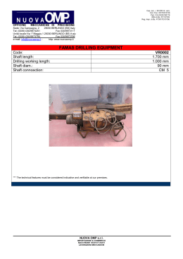
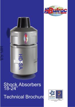
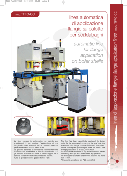
GIUNTI ED ALLUNGHE CARDANICHE
Universal Joints and couplings
trasmissioni cardaniche
Indice / Index
Pag. 2
Presentazione / Presentation
Pag. 4
Applicazioni / Applications
Pag. 6
Cinematica del giunto / Kinematic of universal joint
Pag. 7
Installazione e funzionamento / Installation and use
Pag. 8
Fattore di servizio / Service factor
Pag. 9
Legenda / Notes
Pag. 10
Selezione di un'allunga / Selection of a universal shaft
Pag. 12
Dati tecnici HL 58 - 225 / Technical data HL 58 - 225
Pag. 14
Dati tecnici HS 180 - 350 / Technical data HS 180 - 350
Pag. 16
Dati tecnici HS 390 - 620 / Technical data HS 390 - 620
Pag. 18
Dati tecnici HH 680 - 840 / Technical data HH 680 - 840
Pag. 20
Dati tecnici HH 900 - 1200 / Technical data HH 900 - 1200
Pag. 22
Controflange / Companion flanges
Pag. 24
Fissaggio flange / Flanges connection
Pag. 26
Crociere / Cross assemblies
Pag. 27
Scheda di selezione / Selection form
Pag. 28
Giunti a denti / Gear couplings
1
GIUNTI ED ALLUNGHE CARDANICHE
GIUNTI ED ALLUNGHE CARDANICHE
Universal Joints and couplings
Universal Joints and couplings
Soluzioni innovative per applicazioni industriali
Innovative drive solutions for industrial applications
Presentazione
Presentation
Da oltre 20 anni la società C.A.T. progetta e costruisce riduttori
di velocità e trasmissioni meccaniche di potenza per applicazioni
speciali e ad alta tecnologia. For more than 20 years C.A.T. has been designing and producing
high technology power transmission components.
La progettazione, il calcolo, la realizzazione costruttiva ed i collaudi
nelle varie fasi vengono condotti in accordo alle normative vigenti
e ai criteri imposti dai più importanti Enti di Certificazione (R.I.N.A.,
A.B.S., Lloyd’s Register, G.L.R. ed altri). Design, selection, production and tests during different phases,
are made in accordance with the existing laws and the most
important Certification Companies (R.I.N.A., A.B.S., Lloyd’s
Register, G.L.R. and others).
Da alcuni anni alla produzione di riduttori speciali C.A.T. ha affiancato
le allunghe cardaniche, sempre all’insegna di elevata qualità e
accuratezza. La gamma di produzione copre i settori applicativi
medio-pesanti con coppie fino a 9.000 kNm. La nostra tecnologia
ci consente anche la realizzazione di versioni per applicazioni
speciali non coperte dai normali prodotti commerciali.
Some years ago C.A.T. widened its production with universal
joints and cardan shafts, ever within high quality standard.
The actual range covers medium – heavy duty applications,
with torque up to 9.000 kNm.
Our technology also allows to produce special applications
where the standard isn’t enough.
Dalla progettazione alla verniciatura, ogni fase della produzione è
controllata e verificata per garantire un prodotto di eccellenza, con
i più elevati standard qualitativi.
Tutte le allunghe prodotte superano una serie di rigorosi controlli,
dalla qualità dei materiali fino all’equilibratura dinamica (anche per
grosse dimensioni) ove richiesto dall’applicazione. From design to painting, every production step is checked
and tested to guarantee an excellent product, with the higher
quality standards.
All the shafts produced pass different severe tests, from
material quality to dynanic balancing (for big sizes, too) when
required by the application.
C.A.T. mette a disposizione dei suoi clienti le sue conoscenze
tecniche e la sua esperienza ventennale, sia per la fase progettuale
e di selezione che per l’installazione e la manutenzione dei riduttori
e delle allunghe cardaniche.
C.A.T. puts his technical knowledge and experience at his
customer’s service, both for design and selection and for
installation and maintenance of his gearboxes and cardan
shafts. C.A.T. srl è certificata UNI-EN-ISO 9001:2000.
C.A.T. srl is certified UNI-EN-ISO 9001:2000.
Cenni Storici
History
Le origini dl giunto cardanico o giunto di Hooke risalgono al
sedicesimo secolo e l’effettivo nome dell’inventore rimane incerto.
Il nome del giunto cardanico proviene dal matematico italiano
Gerolamo Cardano (1500 -1576) che teorizzò il principio operativo
di un meccanismo capace di qualsiasi spostamento angolare e
allo stesso tempo capace di trasmettere un moto rotatorio tra due
assi non allineati.
Robert Hooke (1653 -1702), uno scienziato inglese, applicò questi
principi in modo indipendente costruendo una trasmissione per
la movimentazione di una serie di specchi per l’osservazione
sicura del sole. Hooke studiò anche l’uso di due accoppiamenti in
serie per creare un moto uniforme tra due assi rotanti disallineati.
Nel mondo anglosassone questo accoppiamento è noto come
accoppiamento di Hooke o accoppiamento universale.
Tuttavia, anche se l’invenzione viene attribuita a questi scienziati,
un giunto simile era in uso in Cina pochi secoli prima per scopi non
troppo diversi da quelli attuali. I documenti parlano di una lampada
utilizzata a bordo di barche, con la caratteristica di rimanere
sempre dritta. Lo stesso meccanismo venne in seguito in seguito
utilizzato sui compassi. Alcuni documenti parlano di giunti universali
addirittura nell’antica Grecia, approssimativamente 300 anni prima
di Cristo. L’uso di questo tipo di giunto è rimasto marginale per un
lungo periodo, fino al recente boom in parallelo alla crescita del
mercato automobilistico.
The origins of the cardan (universal) joint (or Hooke joint) go back
to the 16th century and the name of its actual inventor is unknown.
The name of cardan joint comes from the Italian mathematician
Gerolamo Cardano (1500 - 1576) who was the first to theorise
the operation principle of a mechanism capable of an angular
displacement and at the same time able to transmit a rotary
movement between two axes not in line.
Rober Hooke (1653 - 1702) an English scientist, applied these same
principles in an independent way, by manufacturing a transmission
for the movement of a number of mirrors for the safe observation
of the sun. Hooke also studied the use of two couplings in series in
order to create a uniform motion between two misaligned rotating
shafts. In the anglo-saxon world, this coupling is known as Hooke
coupling, or universal shaft.
However, although the invention is attributed to these scientists, a
similar joint was in use in China a few centuries before, for purposes
not too different from the current ones.
The documents speak of a lamp used on board of vessels which
has the characteristics of always staying upright.
The same mechanism was then used on the compass, there are
documents speaking of universal joint dating back to 300 years
b.C., in Greece.
The use of this type of joint was marginal for a long period, until the
recent boom due to the growth of the car market.
Assemblaggio cardani presso lo stabilimento di Cerro Maggiore (MI)
Universal joint assembly in the workshop in Cerro Maggiore (MI)
Controllo dimensionale / Dimensional test
Equilibratura / Balancing
Preparazione di
alcuni grossi giunti
Setting up of big joints
Riduttori / Gearboxes
Stabilimento C.A.T. / C.A.T. workshop
2
3
GIUNTI ED ALLUNGHE CARDANICHE
GIUNTI ED ALLUNGHE CARDANICHE
Universal Joints and couplings
Universal Joints and couplings
Applicazioni
Applications
Tipi di allunga per classificazione
Types of universal shafts
Nella sua accezione più semplice il giunto cardanico è composto
da un elemento centrale a forma di croce detto appunto crociera, e
da due semigiunti a forcella, ruotati di 90° l’uno rispetto all’altro.
I quattro perni della crociera ruotano all’interno di boccole calettate
sui bracci delle forcelle, creando un unico accoppiamento rotoidale.
Dalle applicazioni iniziali in campo automobilistico, il collegamento
tramite giunti cardanici si sviluppato sempre più per applicazioni
industriali dove le potenze da trasmettere sono notevolmente
superiori.
Le caratteristiche principali di un giunto cardanico sono:
• la capacità di compensare angoli elevati, permettendo
la trasmissione di coppia tra due alberi non in asse
• nella versione con doppio giunto allungabile, di consentire
contemporaneamente spostamenti radiali e assiali
• la capacità di trasmettere coppie elevate
• i lunghi intervalli di manutenzione
• facilità di montaggio
In its most simple form a universal joint is composed by a central
element, shaped as a cross and by two fork-shaped half joints, at
90° one from the other.
The four studs of the cross rotate inside bushings shrunk-on the
fork arms, thus creating a single rotary coupling.
The universal joints were first employed in the automotive sector,
to become widely used in the most varied industrial applications,
where the powers to be transmitted are considerably greater.
The main characteristics of a universal joint are:
• its capacity of compensating high angles, thus allowing
the transmission of the torque between to shafts not in line
• In its version with double extensible joint, a universal joint
will allow both radial and axial displacements
• It can transmit very high torques
• it requires a very reduced maintenance
• it is easy to install
Le nostre allunghe sono state divise in tre tipologie differenti per
applicazioni industriali medio-pesanti e pesanti, con lo stesso
livello elevato di qualità dei materiali e costruttivo. In entrambi i casi
esistono varianti su richiesta.
Our universal shafts have been divided in two different types, for
medium-heavy and for heavy industrial applications.
The material and construction quality level is the same. In both
cases special types are available upon request.
Serie HL
Per applicazioni industriali. Trasmissioni con flange DIN da diametro
58 mm fino a 225 mm. Coppia da 190 Nm a 25.000 Nm.
Esecuzioni con angolo fino a 35°. Per ogni grandezza è prevista
l’esecuzione con flange maggiorate.
Type HL
For industrial medium duty application. The universal shaft type HL
propose flange DIN from 58 mm to 225 mm diameter with torque
from 190 Nm up to 25.000 Nm. Deflection angle up to 35°.
Each size can be manufactured with bigger flange.
Serie HS
Per le applicazioni industriali la serie HS si propone con flange da
180 a 620 mm, con coppie da 15 a 1200 kNm.
La serie HS coniuga solidità e efficienza per una resa ottimale in
tutte le applicazioni dove la forza è un fattore fondamentale.
Type HS
For the industrial application, the universal shafts type HS propose
flanges from 180 up to 620 mm, with torque up to 1200 kNm.
This type of universal shaft is both solid and efficient, and it is
optimised for those application where the force is the main factor.
La società C.A.T. si è concentrata nello sviluppo di giunti cardanici
per applicazioni industriali. Applicazioni tipiche:
Our company concentrated on the development of universal joints
for industrial applications. Typical applications:
Serie HH
La serie HH nasce per applicazioni industriali con carichi elevati (da
1250 a 9000 kNm) e si pone ai vertici della categoria per capacità e
prezzi. Viene fornita di serie con flangia Hirth per la massima sicurezza
e a richiesta con flangiature differenti, previa verifica della trasmissibilità
della coppia. Coppie superiori sono raggiungibili su richiesta.
Type HH
This type of universal shafts was developed for industrial application
with heavy loading (from 1250 to 9000 kNm and is the top of its
category, both as regards the capacity and the price. It is supplied
with a Hirth type flange, to ensure the maximum safety. Upon
request different flanges can be supplied, after verifying their torque
transmission capacity. Higher torques can be reached, upon request.
• agitatori
• macchine
industriali alimentari
• cartiere
• mescolatori
• macchine
per imballaggio
•macchine per la
lavorazione del legno
•impianti di
laminazione a freddo
• trascinatori
• profilatrici
• generatori
• macchine
per la lavorazione
della gomma
• calandre
• laminatoi per tubi
• carri ponte
• pompe
• banchi prova
• impianti tessili
• spianatrici
• raddrizzatrici
• gru
• stirrers
• industrial
food machines
• paper mills
• mixers
• packing machines
• wood mills
• cold and hot
rolling mills
• pinch rolls
• edging rills
• generators
• rubber mills
• calenders
•pipe mills
• pumps
• test stands
• textile plants
• flattening machines
• straighteners
• cranes and
overhead cranes
Per ogni allunga vengono indicate alcune configurazioni base per
facilitare il dimensionamento. La Lz (lunghezza con lo scanalato nella
posizione di minimo scorrimento) indicata è quella minima raggiungibile
per quella configurazione. Lo scorrimento indicato a catalogo è quello
massimo possibile alla minima lunghezza di costruzione. All'aumentare
delle Lz anche lo scorrimento può aumentare di conseguenza. Per il
raggiungimento di scorrimenti differenti da quelli indicate a catalogo è
comunque consigliabile consultare il nostro ufficio tecnico.
Lo stesso vale per costruzioni di lunghezza superiore a 3 m o con
flange differenti da quella standard a catalogo.
In order to facilitate the rating, we will indicate a few basic
configurations. The Lz (length of the broached shaft, when
completed retracted) indicated is the minimum that can be reached
for that configuration.
The stroke indicated on the catalogue is the maximum admissible
for the minimum construction length.
If Lz is increased the stroke too can be increased. You should consult
our technical office if you need strokes different from those indicated
on the catalogue, as well as for construction length >3 m, or flanges
different from the standard ones indicated on the catalogue.
Ordine di un'allunga
L'ordine di una allunga, una volta effettuata la selezione, deve
riportare i seguenti elementi (lasciando vuoti i campi non necessari,
i.e. Lz e s per SD, s per SF)
Gomma / Rubber
Acciaio / Steel
Carta / Paper
Cemento / Cement
4
Purchase of a universal shaft
Once you have selected a suitable universal shaft, the purchase
order should indicate the following elements (neglecting the
unnecessary fields, such as Lz and s for SD; s for SF)
• Serie (HL, HS, HH)
• Dimensione (225, 250...)
• Tipo di costruzione (L, S, F, D, G, H)
• Lz richiesta (800...)
• Allungamento s richiesto (145..)
• Type (HL, HS, HH)
• Dimension (225, 250 ….)
• Lz required (800 …..)
• Stroke s required (145…)
Le flange non a catalogo, costruzioni speciali, etc. richiedono
una verifica a parte e quindi è necessario contattare direttamente
l'ufficio tecnico per una verifica di fattibilità.
Special flanges nor included in the catalogue or special construction
will require a verification by our technical office; it is therefore
necessary to contact us for a feasibility study.
Esempi di ordini
• Doppi giunti D (es. HH-900 D)
• Fissa (senza scorrimento) F (es. HS 225 F Lf= 900)
• Costruzione corta C (es. HS 225 C Lz=855 s=85)
• Standard S (es. HS 250 S Lf=1200 s=200)
• Costruzione lunga L (es. HS 315 L Lz=1450 s=300)
Example of purchase order
• double joint D (e.g. HH-900 D)
• fixed no extension F (e.g. HS 225 F Lf= 900)
• short construction C (e.g. HS 225 C Lz=855 s=85)
• standard S (e.g. HS 250 S Lf=1200 s=200)
• long construction L (e.g. HS 315 L Lz=1450 s=300)
5
GIUNTI ED ALLUNGHE CARDANICHE
GIUNTI ED ALLUNGHE CARDANICHE
Universal Joints and couplings
Universal Joints and couplings
CINEMATICA DEL GIUNTO / KINEMATICS OF THE JOINT
INSTALLAZIONE E FUNZIONAMENTO / INSTALLATION AND USE
Il singolo giunto universale trasmette un moto rotatorio uniforme in
ingresso come un’uscita non uniforme. Quindi dalla parte del motore
il giunto avrebbe una velocità costante, mentre dal lato opposto
avrebbe un moto periodico di frequenza pari al doppio di quella di
rotazione, sebbene la velocità media rimarrebbe la stessa.
A single universal joint transmits a rotary uniform input motion as
a non-uniform output. Hence, on the motor side the joint has a
constant speed, while it has a periodic motion on the opposite
side, equal to the double of that rotation, although the mean speed
remains the same.
Ruotando la forcella dal lato motore di una frazione di giro, anche
la forcella accoppiata avrà una rotazione, ma gli angoli saranno
differenti, secondo la formula
By rotating the fork on the motor side of a fraction of turn, also the
coupled fork will rotate, but the angles will be different, according
to the formula:
tan φ1
tan φ2 =
cos β
tan φ1
tan φ2 =
cos β
Dove φ1=angolo di rotazione lato motore
φ2=angolo di rotazione lato albero
β =angolo di lavoro dell’allunga.
La velocità angolare dei due mezzi giunti dipende direttamente dal
fatto che la metà trainata del giunto ruota con anticipo nel primo
quarto di rotazione, e con ritardo nel secondo quarto di rotazione.
ω2
cos β
=
1- cos2 φ1 sin2 β
ω1
Where: φ1= rotation angle, motor side
φ2= rotation angle, shaft side
β = universal shaft working angle
The angular speed of the half joints depends directly on the fact that
the half section dragged by the joints rotates with advance in the first
quarter of rotation and with delay in the second quarter of rotation:
ω2
cos β
=
1- cos2 φ1 sin2 β
ω1
Con
ω1 = velocità angolare lato motore
ω2 = velocità angolare lato albero
β = angolo di lavoro dell’allunga
Il grado di irregolarità del periodo (errore cardanico) è direttamente
proporzionale all’angolo di lavoro dell’allunga, con due massimi e
due minimi per giro.
Where: ω1 = angular speed, motor side
ω2 = angular speed, shaft side
β = universal shaft working angle.
The degree o irregularity in the period (cardanic error) is directly
proportioned to the universal shaft working angle with two maxima
and two minima per rotation.
a φ1=90° e 270°
a φ1=0° e 180°
φ1=90° e 270°
φ1=0° e 180°
a
a
La massima ampiezza di oscillazione tra ingresso e uscita della
velocità angolare viene calcolata come segue.
The maximum oscillation width (between input and output) of the
angular speed is calculated as follows:
Disposizione dei giunti universali
Come è evidente, il singolo giunto è limitato ad applicazioni a basse
MONTAGGIO - INSTALLATION
velocità e ad un angolo di lavoro di pochi gradi.
srl
Costruzione Riduttori
Speciali
Le variazioni
di moto periodiche esistenti su un giunto universale
singolo possono essere cancellate installando un secondo giunto
accoppiato al primo. Installando i due giunti MONTAGGIO
con gli angoli Aβ1Ze β2
INSTALLATION
uguali
secondo le disposizioni a Z o W, leZvariazioni
di velocità
ß1
angolare imposte dal primo giunto vengono compensate da quelle
imposte dal secondo. Con un opportuno accoppiamento è quindi
possibile ottenere un moto uniforme in ingresso e in uscita.
ß2
ß1=ß2
Arrangement of the universal shafts
The single joint is limited to low speed application, with a
working angle of few degrees.
The periodic motion variations existing on a single universal
joint can be eliminated by installing a second joint, coupled
to the first one. If we install the two joints with the angles β 1
and β2 equal, in a Z or W arrangement, the angular speed
variations imposed by the first joint will be compensated by
those imposed by the second joint.
MONTAGGIO - INSTALLATION
Costruzione Riduttori Speciali
MONTAGGIO A W
W INSTALLATION
ß1
srl
MONTAGGIO A Z
Z INSTALLATION
ß1
For universal shafts movimentation, refer to attached drawing (Sollevamento sicuro / safe lifting). If possible use lifting rings for movimentation.
Before installation it is not needed to clean the inside of the universal
shaft, since shaft is given already lubricated and ready to start. Remove rust protection covering, paint and grease from flange surface, on both universal shaft flange and connection on the motor/
gearbox/driven machine.
Check carefulli that the flange dimensions are fully compatible with
the connection on the machine. Installation has to be like one of
the two configurations shown on the drawing, W or Z. Check carefully for disalignment.
Check that the two angles β1 and β2 are the same.
Check that the spline and sleeve are mounted with the red facing arrows aligned. The flange bolts must be locked simmetrically,
with the shoun torque, using a dynanometric key. After 24 working
hours of the new universal shaft, lock the bolts again as before.
This operation should be made twice to avoid that the bolts release
by themselves.
Per lo spostamento dell'allunga,fare riferimento al disegno allegato (Sollevamento sicuro / Safe Lifting). Possibilmente attuare lo
spostamento tramite golfari. Non è necessario pulire le allunghe
internamente prima della loro installazione, dato che le allunghe
sono fornite con il lubrificante.Rimuovere la protezione antiruggine, la vernice, il grasso o lo sporco dalla superficie delle flange,
sia dell’allunga sia dell’apparecchiatura cui dovrà essere collegata.
Assicuratevi che le dimensioni delle flange dell’allunga siano compatibili con quelle dell’apparecchiatura da collegare.
L'installazione deve avvenire secondo una delle due configurazioni
iriportate nel disegno, W o Z. Verificare attentamente la presenza di
eventuali disallineamenti. Assicurarsi che i due angoli β1 e β2 siano
uguali. Assicuratevi che la posizione degli alberi brocciati maschio
e femmina corrispondano (le frecce rosse devono essere allineate).
Serrare i dati delle flange in modo simmetrico, secondo la coppia
indicata, con una chiave dinamometrica. Dopo 24 ore di funzionamento dell’allunga appena installata, serrare nuovamente i dati
come sopra indicato. Questa operazione dovrebbe essere ripetuta
due volte, per evitare allentamenti.
TRASPORTO E IMMAGAZZINAGGIO
Transport and Storage
Le allunghe cardaniche con alberi brocciati dovrebbero essere traUniversal shaft should be carried and moved in the horizontal posportate e movimentata in posizione orizzontale.
sition (i.e with the shaft parallel to the ground).
MONTAGGIOWe
- INSTALLATION
Raccomandiamo l’uso di corde non metalliche per il loro sollevasuggest the use of non-metallic ropes for lifting.
srl
Costruzione
Riduttori
Speciali
mento. Fare attenzione a non danneggiare i cuscinetti nell’appogKeep attention to not damage bearings while lowering the shaft to
giarle a terra. Fare riferimento al disegno allegato (Sollevamento
the ground. Use the attached drawing (Sollevamento sicuro / Safe
MONTAGGIO A Z
sicuro / Safe Lifting). Le allunghe dovrebbero essere immagazzinalifting). for reference.
Z INSTALLATION
ß1
te in un posto asciutto, non direttamente esposte alla luce solare
Universal shafts should be stored in a dry space,and not exposed
MONTAGGIO - INSTALLATION
e alla pioggia. Evitare di immagazzinare le allunghe cardaniche
in
to sun and rain. Avoid to store the universal shafts near acid, alkasrl
Costruzione Riduttori Speciali
presenza di solventi acidi, alcalini o organici.
line or organic reagents.
ß1=ß2
ß2
MONTAGGIO A Z
Maintenance and
repair
Z INSTALLATION
New universal shafts do not require grease filling. It is needed a
AW
grease fillingMONTAGGIO
dor universal
shafts that have been stored for more
W INSTALLATION
than 6 months . Bearings and shafts should be lubricated periodiß2
cally while working. In standard conditions
grease should be refilled
every 500 working hours.
ß2
For universal shafts working
at high temperature, grese should be
MONTAGGIO A W
refilled every week (140Whours).
INSTALLATION
Verify the grase kind, standard or high temperature.
MANUTENZIONE E RIPARAZIONE
ß1
Le allunghe nuove non richiedono riempimento di grasso. È però
necessario un rabbocco di grasso per allunghe che siano state
immagazzinate per più di 6 mesi. È necessario lubrificare perioß1=ß2
dicamente i cuscinetti e gli alberi quando lavorano. In condizioni
normali, il grasso dovrebbe essere aggiunto ogni 500 ore di funß1
zionamento. Per allunghe che lavorino ad
alte temperature, aggiungere grasso ogni settimana (140 ore). Verificare il tipo di grasso
utilizzato, standard o per alte temperature.
ß1=ß2
Controlli periodici da eseguire
Periodical Controls
ß1
ß2
Controllare se la rumorosità è anomala
Check if noise is abnormally high
Controllare se l’oscillazione radiale è anormale
Check if radial swinging is abnormal
SOLLEVAMENTO
- LIFTING
Controllare se i bulloni sono allentati
Check
if bolts are loose
ß1=ß2
Controllare se la lubrificazione è buona
Check if lubrication is enough
Qualunque anomalia dovrebbe essere eliminata immediatamente.
Any anomaly should be taken care immediately
SOLLEVAMENTO IN
SICUREZZA
SAFE
LIFTING
SOLLEVAMENTO
- LIFTING
ß2
ß1=ß2
ß1=ß2
ß2
SOLLEVAMENTO IN
SICUREZZA
SAFE LIFTING
MONTAGGIO A W
W INSTALLATION
SOLLEVAMENTO - LIFTING
6
ß1
ß2
7
GIUNTI ED ALLUNGHE CARDANICHE
GIUNTI ED ALLUNGHE CARDANICHE
Universal Joints and couplings
Universal Joints and couplings
FATTORE DI SERVIZIO / SERVICE FACTOR
The table below shows some tipical values for service factors.
These values are only an example.
The selection of the real value must be based on the typical
estimation of admissible overloads resulting from the process
analisys and the know how of the applications and considering the
existing motor.
As you can see, the same machine may fall in different categories
as a consequence of different factors can be considered.
For this reason our Technical Department is at your disposal to
provide you with the correct selection based on our experience of
many applications already realized.
Qui di seguito sono riportati alcuni valori tipici per i fattori di servizio
applicati. I fattori di servizio sotto indicati costituiscono solo
esemplificazioni. La selezione di un valore si deve basare su una
stima del sovraccarico possibile data dall'analisi del processo e dal
know-how tecnologico sulle applicazioni e dal tipo di motorizzazione
applicata. Come si può notare, la stessa macchina può anche
ricadere in più categorie in conseguenza di diversi fattori.
Per questo motivo il nostro Ufficio Tecnico è sempre disponibile
per fornire in tempi brevi un dimensionamento basato sulla
nostra esperienza e sulle numerose applicazioni differenti finora
realizzate.
Applicazione
Coppia costante
Generatori continui, piccoli ventilatori, pompe
centrifughe, macchine utensili, macchine da stampa,
nastri trasportatori.
Application
Constant load
Continuous generators, little fans,
centrifugal pumps, machine tools, printing machines,
belt conveyors.
Carico leggero
Generatori a carico variabile, pompe centrifughe,
nastri trasportatori a carico continuo, macchine per la
lavorazione del legno, laminatoi per barre, ventilatori.
Light load
Variable load generators, centrifugal pumps, conveyor
belts with discontinuous load, wood machines,
bar mills, fans.
Carico medio
Ventilatori di grosse dimensioni, trasmissioni marine,
tavole vibranti, calandre, pinch rolls, laminatoi per
tubi, comandi argano, miscelatori, laminatoi continui,
scavatori a ruota, presse, trivelle rotative, compressori
monocilindrici, pompe monocilindriche, piegatrici,
cartiere.
Medium load
Big fans, marine transmissions, vibrating tables,
calanders, pinch rolls, tube mills, winch drives, mixers,
continuous mills, exavators, presses, drilling machines,
monocilynder compressors, monocilynder pumps,
paper mills.
Carico gravoso
Tavole oscillanti continue, laminatoi di sezione media,
laminatoi per tubi di grossa dimensione, coinvogliatori
vibranti, macchine per laminazione continua, raddrizzatoi,
laminatoi a freddo, mulini.
Carico molto gravoso
Avvolgitori, cesoie per piastre, mulini.
Legenda / Notes
Heavy load
Continuous oscillating tables, midium size mills,
big tube mills, vibrating conveyors, machines
for continuous milling, straightners, cold mills, mills.
High heavy load
Winders, plate shears, mills.
8
Ks
1,1 - 1,5
Tn [Nm]
Momento torcente massimo di esercizio applicabile per un breve periodo di tempo (10^3 cicli)
Maximum torque applicable for a short time (10^3 cycles)
Tdw [Nm]
Momento torcente pulsante applicabile per un breve periodo
Pulsing torque applicable for a short period
Tk [Nm]
Momento torcente alternato applicabile per un breve periodo
Alternate torque applicable for a short period
Tc [Nm]
Momento torcente per la durata dei cuscinetti
Max torque for bearing life calculation
Lz [mm]
Lunghezza Chiusa Minima
Minimun Collapsed Length
s [mm]
Allungamento Standard
Standard Stroke
Lf [mm]
Lunghezza Fissa
Fixed Length
ß° [°]
Angolo di deflessione massimo
Maximum Deflection Angle
1,5 - 2,0
2,0 - 3,0
3,0 - 5,0
5,0 - 10,0
Componenti dell’allunga
Components of the universal shaft
Crociera
La crociera è l’elemento centrale dell’allunga, quello il cui
dimensionamento è più critico.
Sono fondamentali sia i materiali della crociera, che quello dei rulli,
quindi sono sottoposte a rigorosi controlli per garantirne la qualità.
I cuscinetti sono costruiti per durare e funzionare nelle condizioni
più gravose.
CROSS
It is the central element of the universal shaft, and its rating is the
most critical. Fundamental are both the material of the cross and
that of the rollers, that are therefore submitted to the most rigorous
tests to ensure a good quality.
The bearings are built to ensure a long life and to operation in the
heaviest conditions.
Flange e forcelle
Per flange e forcelle il dimensionamento richiede studi accurati del
momento trasmissibile e delle deformazioni sotto carico.
Le forcelle e le flangie sono prodotte a partire da forgiati con elevati
standard qualitativi sia dal punto di vista delle lavorazioni che dei
materiali.
FLANGES AND FORKS
The rating of the flanges and forks required accurate studies of the
transmissible moment and of the deformations under load.
The forks and the flanges are manufactured starting from a forging,
with high quality standards, both as concerns the material and the
working.
Albero dentato e manicotto dentato
L’albero dentato e il manicotto permettono lo scorrimento relativo
dei giunti variando la lunghezza effettiva dell’allunga, per le
applicazioni in cui la distanza tra sorgente e utilizzatore sia variabile
oppure per facilitare le operazioni di montaggio e smontaggio.
La dentatura subisce un trattamento di tempra a induzione ed è
costruita in modo da minimizzare i giochi radiali.
BROACHED SHAFT AND BROACHED SLEEVE
The broached shaft and sleeve allow the relative sliding of the joints
and the actual variation of the universal shaft length, for those
application where the distance between the driver and the driven
element is variable, or to facilitate the assembly and dismantling
operations. The broached part is induction hardened and is built in
such a way as to minimize the radial backlashes.
A richiesta la dentatura può essere nitrurata.
Upon request, nitrited broached can be supply.
9
GIUNTI ED ALLUNGHE CARDANICHE
GIUNTI ED ALLUNGHE CARDANICHE
Universal Joints and couplings
Universal Joints and couplings
SELEZIONE DI UN'ALLUNGA / SELECTION OF A UNIVERSAL SHAFT
La selezione di un’allunga procede attraverso una serie di passi
successivi per avere una scelta sicura ed efficace.
Un sottodimensionamento di una o più caratteristiche comporta il
rischio di rotture o malfunzionamenti ed è quindi da evitarsi con la
massima attenzione. I passi sono i seguenti.
1.Determinazione delle caratteristiche geometriche.
Determinare gli spazi in cui andrà installata l’allunga e verificare
le lunghezze minime e massime, eventuale corsa, angolo di
lavoro e massima dimensione di flangia.
2. Determinare la coppia agente sull’allunga.
Tipo di lavoro (continuo, pulsato, alternato).
Verificare gli sforzi ammissibili.
3. Determinare la vita operativa teorica a partire dai dati
di catalogo.
4. Selezionare la flangia.
Verificare la trasmissibilità della coppia attraverso la flangia.
5. Verifica delle velocità critiche per l’allunga.
The selection of a universal shaft requires several steps, in order to
make a safe and efficient choice.
The under rating of one or more characteristics will cause the
failure of malfunctioning and should be avoided with he maximum
attention. The procedure is:
1. Determine the geometrical characteristics; the spaces where
the universal shaft will be installed; verify the minimum
and maximum length, the stroke, if any, the working angle
and the maximum dimension of the flange.
2. Determine the torque acting on the universal shaft;
the type of work (continuous, pulsating, alternating);
verify the admissible stress.
3. Determine the theoretical working life span, using the
catalogue data.
4. Select the flange and verify that the torque can be transmitted
through the flange.
5. Verify the critical speeds of the universal shaft.
Determinazione delle
caratteristiche geometriche
Considerate attentamente il macchinario su cui verrà installata
l’allunga
• Determinate la distanza tra le flange esterne richiesta,
e determinate (dal catalogo) quali tipi di allunghe
possono essere adatte
• Scegliete tra allunghe fisse o con corsa.
• Determinate la dimensione della flangia
• Determinare se siano necessari o meno mancioni,
e eventualmente sottrarre dallo spazio disponibile quello
necessario ai mancioni.
Determination of the geometrical
characteristics
Consider very carefully the equipment where the universal shaft
will be installed.
• Determine the required distance between the external flanges
and choose on the catalogue the suitable type.
• Choose between fixed or extensible universal shaft
• Determine the dimension of the flanges
• Determine whether sleeves are required and in this case
subtract the space required by the sleeve from the total
available space.
Determinare la coppia agente
sull’allunga
Il calcolo della massima coppia ammissibile richiede di conoscere
la massima potenza (in kW/h) erogata dal motore e a quale numero
di giri. La coppia sarà :
to Determine the torque acting
on the universal shaft
For the calculation of the maximum admissible torque you will need
to know the power (kW/h) supplied by the motor and at which
speed. The torque will be:
T = P*9550/n[Nm]
T = P*9550/n[Nm]
dove P[kW] è la potenza erogata dal motore e n[rpm] è la velocità di rotazione dell’allunga in giri al minuto. Per verificare il carico
massimo ammissibile va considerato anche un fattore di servizio
ks che tiene conto del tipo di applicazione; in pratica è un moltiplicatore della coppia erogata che tiene conto del tipo di servizio
dell'allunga. Il valore per la verifica dipende dalla frequenza di applicazione del carico. Una coppia applicata unidirezionalmente a
valore costante (o quasi) viene verificato come Tn, ovvero come un
valore applicabile per un breve periodo di tempo (103 cicli) senza
che insorgano deformazioni permanenti nel giunto.
Una coppia applicata unidirezionalmente con una fluttuazione del
valore applicato di ampiezza con lo stesso ordine si verifica come
Tdw, ovvero come un carico pulsante applicabile per un breve periodo di tempo (103 cicli) senza che insorgano deformazioni permanenti nel giunto. Una coppia in cui il verso di applicazione sia
variante nel tempo con un intervallo e una ampiezza definiti si definisce come Tk ovvero come un carico alternato applicabile per un
Where: P[kW] is the power supplied by the motor and n[rpm] is the
rotation speed of the universal shaft in rpm.
In order to verify the maximum admissible load a safety factor Ks
must be considered too.
It accounts for the type of application and it is practically a multiplier
of the torque according to the type of service of the universal
shaft.
The value for the verification depends on the load application
frequency. A torque applied unidirectionally at a nearly constant
value, is defined as Tn, i.e. as a value applicable for a short period
(103 cycles), with no permanent deformations of the joint.
A torque applied unidirectionally with a fluctuation of the value
applied is defined as Tdw, i.e. as a pulsating load that can be
applied for a short period of time (103 cycles), with no permanent
deformations of the joint.
A torque with a direction of application varying in time with
a definite interval and width, is defined Tk, i.e. as an alternating
breve periodo di tempo (103 cicli) senza che insorgano deformazioni
permanenti nel giunto.
load applicable for a short period (103 cycles), with no permanent
deformations of the joint.
Determinare la durata
La vita teorica di un'allunga dipende da 3 fattori:
Determination of the life span
The theoretical life of an universal shaft depends on three factors:
β
• Average working angle
β
• velocità di rotazione in rpm
n
• Rotation speed in rpm
n
• momento torcente trasmesso T
• Transmitted torque
T
• angolo di lavoro medio
Questi valori in funzione della coppia di catalogo TC forniscono la
vita teorica in ore Lh10 con la formula
TC
__
T
10
__
3
These values, as a function of the catalogue torque TC will give the
theoretical life in hours Lh10 with the formula
TC
__
T
1,5*10 6
* ___________
n* β
1,5*10 6
* ___________
n* β
ESEMPIO
Un riduttore con rapporto di riduzione 10 è alimentato da un motore da 150 kW a 1200 rpm. Velocità in uscita: 1200/10=120 rpm.
Sono richieste 20000 h di servizio.
Example
A gearbox with a reduction ratio 1:10 is fed by a 150 kW motor at
1200 rpm. Output speed: 1200/10 = 120 rpm. 20 000 hours of
service are required:
T = 300*9550 / 120 = 23875 Nm
T = 300*9550 / 120 = 23875 Nm
Ipotizziamo come azione un mescolatore (Ks =1.75)
We consider to use it with a mixer (Ks =1.75)
Tnmin = T*Ks = 41781.2 Nm
Tnmin = T*Ks = 41781.2 Nm
Il valore è superiore a quello ammissibile per una HS 180.
Risulta quindi necessario utilizzare almeno una HS 225
che ha:
The value is greater than the one accepted for a universal shaft HS
180. It will therefore be necessary to use at least a universal shaft
HS 225, which has
Tn= 55 kNm
Tn= 55 kNm
We will consider a working angle of 2°
Ipotizziamo un angolo di lavoro di 2°
10
10
__
3
Lh10
22
____
23,9
10
__
3
*
1,5 10 = 4762 h
120 * 2
6
*
___________
Lh10
Essendo la durata piuttosto bassa, ripetiamo il dimensionamento
con una HS 250
Tn = 80 kNm
Lh10
34,6
____
23,9
10
__
3
22
____
23,9
10
__
3
1,5*10 6
* ___________ = 4762 h
120 * 2
Since the life span is rather low, we will repeat the rating with an
HS 250.
Tn = 80 kNm
1,5 10
= 21452 h
*
120 * 2
6
*
___________
Lh10
34,6
____
23,9
10
__
3
1,5*10 6
* ___________ = 21452 h
120 * 2
Quindi una HS 250 rientra pienamente nei requisiti necessari.
Hence, a universal shaft HS 250 will perfectly meet the requirements.
Allunghe serie HH 900 / Universal shafts HH 900
Allunghe serie HH 900 / Universal shafts HH 900
11
GIUNTI ED ALLUNGHE CARDANICHE
GIUNTI ED ALLUNGHE CARDANICHE
Universal Joints and couplings
Universal Joints and couplings
HL 58 - 225
Versione Standard
Standard Type
s
e
t1
0 d6
0 d7
Lz
Tipo
Type
S
65
75
90
100
120
150
180
200
Tn (Nm)
190
254
514
816
1350
2575
5250
9600
16800 25000
Tdw (Nm)
126
179,2
364
581
840
1610
3150
5880
12320 16380
Tk (Nm)
90
128
260
415
600
1150
2250
4200
8800
Tc (Nm)
149
230
390
640
1062
1860
3490
5835
11400 15800
β(°)
35
35
35
35
35
35
35
25
25
25
255
35
2,2
150
1,7
128
1,3
285
40
3
175
2,4
156
1,95
335
40
5
200
3,8
180
3,1
385
45
6,6
240
5,7
208
5
445
55
9,5
260
7,7
220
7
500
80
17
295
13,1
252
12,3
590
80
32
370
23
340
22
640
80
40
430
28
348
30
775
100
76
530
55
440
56
860
120
128
600
98
480
96
Ød1
58
65
75
90
100
120
150
180
200
225
Ød3
47
52
62
74,5
84
101,5
130
155,5
170
196
Ød2 (H7)
30
35
42
47
57
75
90
110
125
140
t1
1,5
1,7
2
2,5
2,5
2,5
3
4
4
5
b
Versione Fissa
Fixed Lenght Type
60 °
0 d4
Lf
30 °
3
0d
F
30 °
Taglia
Size
58
0 d2
0 d1
ß°
e
Lz (mm)
s (mm)
m (kg)
Lf (mm)
m (kg)
Lf (mm)
m (kg)
S
F
n.6 Fori / Holes
D
22 ° 30'
0 d4
11700
45
Versione Doppio Giunto
Double Joint Type
Lf
225
°
3
0d
38 °
D
Ød6
n.8 Fori / Holes
450
0 d4
38*1,5 45*1,5 63,5*2,5 63,5*2,5 89*2,5 89*2,5 120*3 120*3 127*5,5 140*6,5
300
3
0d
mL (100 mm)
0,14
0,16
0,38
0,38
0,53
0,53
0,87
0,87
1,65
2,14
e
32
39
45
52
55
63
85
87
110
120
b
3,5
4,5
5,5
6
8
8
10
12
14
15
z
4
4
6
4
6
8
8
8
8
8
Ød4
5,1
6,5
6,5
8,5
8,5
10,5
13
15
17
17
Flange Bolt
M5
M6
M6
M8
M8
M10
M12
M14
M16
M16
450
n.4 Fori / Holes
12
13
GIUNTI ED ALLUNGHE CARDANICHE
GIUNTI ED ALLUNGHE CARDANICHE
Universal Joints and couplings
GiuNti e TrasmissioNi CardaNici - UNiversal JoiNts aNd Shafts
From HS 390 to HS
620
Lz Lz
0 d7
0 d6
e
s
e
s
t1
X
0 d2
ß°
3 d3
0d 0
0°
° 53°
30 4
30 °
22 ° 30 '
0 d4
0 d4
Lf
38 °
15 °
n.10 Fori / Holes
n.8 Fori / Holes
0 d4
0 d4
10°3200°°
Lf
20
°
3
0 d0 d3
Lf
D
G
n.16 Fori / Holes
30 °20°
° 20 °
30
Versione Doppio Giunto
Double Joint Type
D
180
225
250
285
315
350
26
20
13
12,4
15
55
39
26
22
15
80
49
35
34,6
15
115
70
50
50,8
15
170
106
71
70,2
15
225
140
100
93,6
15
785
130
78
450
58
420
48
855
150
124
540
92
540
90
955
150
171
600
152
600
130
1020
150
245
690
215
660
189
1220
200
378
800
306
800
270
1415
235
610
900
440
900
355
180
155,5
90
5
125*13
3,5
120
18
25
9
6
15
M14
225
196
105
5
157*21
6,8
130
20
32
12,5
8
17
M16
250
218
105
6
181*21
7,8
145
25
40
15
8
19
M18
285
245
125
7
200*23
9,5
165
27
40
15
8
21
M20
315
280
130
8
225*26
12,5
185
32
40
15
10
23
M22
350
310
210
8
245*19
10,6
195
35
50
16
10
23
M22
n.6 Fori / Holes
Lf
F
F
30 °
Lf
Versione Fissa
Fixed Lenght Type
Taglia
Size
Tn (kNm)
Tdw (kNm)
Tk (kNm)
Tc (kNm)
β(°)
30 °
Y
b
3
0d
S
S
HS 180 - 350
Tipo
Type
60 °
0 d4
0 d1
Versione Standard
srl
Standard
Costruzio0e
Riduttori Type
Speciali
Universal Joints and couplings
15 °
n.10 Fori / Holes
S
F
D
Lz (mm)
S (mm)
m (kg)
Lf (mm)
m (kg)
Lf (mm)
m (kg)
Ød1
Ød3
Ød2 (H7)
t1
Ø d6
mL (kg/100 mm)
e
b
X(h9)
Y
z
Ød4
Flange Bolt
s
Lz
H
14
15
GIUNTI ED ALLUNGHE CARDANICHE
GIUNTI ED ALLUNGHE CARDANICHE
Universal Joints and couplings
Universal Joints and couplings
GiuNti e TrasmissioNi CardaNici - UNiversal JoiNts aNd Shafts
From HS 390 to HS
620
Lz
e
t1
X
ß°
0 d7
0 d6
e
S
HS 390 - 620
s
0 d1
Standard type
0 d2
srl
Versione
Standard
Costruzio0e
Riduttori Speciali
Tipo
Type
Tn (kNm)
Tdw (kNm)
Tk (kNm)
Tc (kNm)
β(°)
Y
b
Versione Fissa
Fixed Lenght type
Lf
30 °
0 d4
30
0°
° 3
S
3
0d
F
F
Versione Doppio Giunto
Double Joint type
15 °
Lf
D
n.10 Fori / Holes
G
D
0 d4
10° 20 °
20
°
20°
0d
3
Lf
n.16 Fori / Holes
G
Versione con Corsa Flangiata
Stroke Type, Flanged design
H
20 °
Versione Fissa Flangiata
Fixed Lenght Type, Flanged design
s
Lz
H
16
Taglia
Size
Lz (mm)
s (mm)
m (kg)
Lf (mm)
m (kg)
Lf (mm)
m (kg)
Lf (mm)
m (kg)
Lz (mm)
s (mm)
m (kg)
Ød1
Ød3
Ød2 (H7)
t1
Ød6
mL (100 mm)
e
b
X(h9)
Y
z
Ød4
Flange Bolt
390
440
490
550
620
325
224
160
122,7
15
500
350
250
165
15
730
483
345
330
15
1000
700
500
335
15
1250
910
650
460
15
1530
170
804
1010
590
1120
665
860
510
1710
170
860
1690
190
1122
1130
820
1230
920
1040
780
1880
190
1205
1850
190
1468
1240
1090
1360
1240
1080
970
2050
190
1568
2060
240
2154
1400
1560
1550
1765
1220
1330
2310
240
2454
2280
250
2830
1520
2100
1720
2390
1360
1865
2540
250
3235
390
345
235
8
273*21
13,00
215
40
70
18
10
25
M24
440
390
255
10
325*25
18,50
260
42
80
20
16
28
M27
490
435
275
12
351*30
23,75
270
47
90
22,5
16
31
M30
550
492
320
12
402*32
29,12
305
50
100
22,5
16
31
M30
620
555
380
12
426*40
38,08
340
55
100
25
18
38
M36
17
GIUNTI ED ALLUNGHE CARDANICHE
GIUNTI ED ALLUNGHE CARDANICHE
Universal Joints and couplings
Universal Joints and couplings
Giunti e Trasmissioni Cardanici - Universal Joints and Shafts
HH 680-1200
Versione Standardsrl
Costruzio�e Riduttori Speciali
Standard
Type
s
e
� d6
� d7
e
Lz
HH 680 - 840
Taglia
Size
680
700
750
780
800
840
1640
1372
980
15
1750
1470
1050
15
2250
1890
1350
15
2500
2100
1500
15
2670
2240
1600
15
3100
2604
1860
15
3230
250
4880
1940
3220
1540
3150
3460
250
5400
2100
3530
1600
3450
3620
250
8000
2400
4500
1840
4300
4000
250
8450
2500
5400
1920
4680
4000
250
9070
2500
5800
1920
5050
4250
250
11800
2680
7470
2120
6400
680
635
550
560
385
70
24
26
M24
700
635
570
560
400
70
24
26
M24
750
695
610
620
460
95
24
31
M30
780
725
640
660
480
95
24
31
M30
800
745
660
660
480
95
24
36
M30
840
775
710
660
53
110
24
38
M36
� d1
ß°
Tipo
Type
S
Tn (kNm)
Tdw (kNm)
Tk (kNm)
β(°)
b
Versione Fissa
Fixed Lenght Type
Lf
S
F
F
D
Versione Doppio Giunto
Double Joint Type
Lf
Ød1
Ød3
Ød2 (H9)
Ød6
e
b
z
Ød4
Flange Bolt
D
°
15° 15
18°
� d3
� d4
Flange con serraggio Hirth
n.20 Fori / Holes
� d3
18 °
� d4
e
� d1
� d3
� d2
b
Lz (mm)
s (mm)
m (kg)
Lf (mm)
m (kg)
Lf (mm)
m (kg)
n.24 Fori / Holes
Flanges with Hirth serration
18
19
GIUNTI ED ALLUNGHE CARDANICHE
GIUNTI ED ALLUNGHE CARDANICHE
Universal Joints and couplings
Universal Joints and couplings
Giunti e Trasmissioni Cardanici - Universal Joints and Shafts
HH 680-1200
Versione Standardsrl
Costruzio�e Riduttori Speciali
Standard
Type
s
e
� d6
� d7
e
Lz
HH 900 - 1200
Taglia
Size
900
920
1000
1060
1100
1200
3800
3192
2280
15
4050
3402
2430
15
5200
4368
3120
15
6500
5460
3900
15
6900
5796
4140
15
9000
7560
5400
15
4580
300
15900
2950
9980
2280
8420
4850
300
16500
2950
10500
2280
8950
4770
300
19900
3130
12300
2380
10600
4950
300
22000
3200
14500
2480
12100
5100
300
27500
3300
15800
2500
13500
5660
300
34800
3570
19500
2720
16900
900
835
740
750
570
120
24
38
M36
920
855
760
750
570
120
24
38
M36
1000
915
840
790
595
130
20
50
M48
1060
980
840
800
620
130
20
50
M48
1100
1015
920
850
625
130
20
50
M48
1200
1100
1000
900
680
130
20
58
M56
� d1
ß°
Tipo
Type
S
Tn (kNm)
Tdw (kNm)
Tk (kNm)
β(°)
b
Versione Fissa
Fixed Lenght Type
Lf
S
F
F
D
Versione Doppio Giunto
Double Joint Type
Lf
Ød1
Ød3
Ød2 (H9)
Ød6
e
b
z
Ød4
Flange Bolt
D
°
15° 15
18°
� d3
� d4
Flange con serraggio Hirth
n.20 Fori / Holes
� d3
18 °
� d4
e
� d1
� d3
� d2
b
Lz (mm)
s (mm)
m (kg)
Lf (mm)
m (kg)
Lf (mm)
m (kg)
n.24 Fori / Holes
Flanges with Hirth serration
20
21
srl
GIUNTI ED ALLUNGHE CARDANICHE
A
Costruzione Riduttori Speciali
Universal Joints and couplings
Controflange - Counterflanges
GIUNTI ED ALLUNGHE CARDANICHE
srl
Controflange
- Counterflanges
Universal
Joints and couplings
L
P
Controflange
- Counterflanges
b
t1
srl
A
L
srl
CONTROFLANGE
/ COMPANIONt1FLANGES
b
s
A
L
Y b L
A
s
t1
Costruzione Riduttoris Speciali
S
Costruzione Riduttori Speciali
S
Ød5
Ød6
S
Ød5
Ød6
Ød5 Ød5
Ød6 Ød6
S
Ød1
Ød3
Ød2
X
Ød1 Ød1
Ød3 Ød3
Ød2 Ød2
X X
t2
t2
t2
S
t2
P
S
Y
Y
Y
b
S
P
P
s
Y
b
b
L1
S
P
P
S
s
Ød5
b
s
Ød6
S
s
P
S
Ød5
Ød5
d4
i Ø Ød4
r
o
f
s
n°z hole
z
°
n
d4
i Ø Ød4
r
o
f
s
n°z hole
z
n°
d4
ri Ø Ød4
o
f
esd4
n°z holØ
4
z
i
°
r
n fo s Ød
n°z hole
n°z
Ød5 Ød5
Ød1
Ød3
Ød2
x
Ød1
Ød3
Ød2
x
L
t1
Ød1 Ød1
Ød3 Ød3
Ød2 Ød2
x
x
t2
s
L
Y
t1
t2
C
P
P
d4
ri Ø Ød4
o
f
s
L
n°z hole
z
°
n
Y
d4
L1
i Ø Ød4
t1
r
o
f
s
Y L
n°z hole
L1
z
n°
d4
t1
ri Ø Ød4
o
f
esd4
L
n°z holØ
4
z
i
°
t1
Scheda di richiesta / Requirement form
n for s Ød
L
n°z hole
n°z report required tolerance.
Tutte le misure indicate con * dovranno riportare la tolleranza richiesta/ All measures marked * shall
t1
Y
L1
S
universal shafts and are the ideal solution for high torques.
s
Ød6
sono la soluzione ottimale per coppie elevate
C
C
C
P
t1
Ød6 Ød6
There are several types of flanges that can be made upon customers’ request, with special holes or machining, without keys, with
different centering etc.
Two special flanges for high loading are the “dog toothed” and
those with Hirth toothing.
The dog toothed flanged universal shaft is often used in the rolling
mills thanks to its special characteristics.
The Hirth toothed flanges are used as a standard on the HH type
L
s
Ød5
Esistono molte tipologie di flange che possono essere realizzate su
richiesta del cliente, con forature o lavorazioni particolari, prive di
chiavetta, centraggi differenti etc..
Due tipi di flange speciali per carichi elevati sono quelle a Denti di
Cane e con Dentatura Hirth.
La flangia a Denti di Cane è spesso utilizzata nei laminatoi per le
sue particolari caratteristiche.
Le flange a Dentatura Hirth sono utilizzate di serie sulla linea HH e
t1
Ød5 Ød5
SPECIAL FLANGES
C
Y
L
s
Ød1
Ød3
Ød2
X
Flange Speciali
B
P
4
Ød d4
i
r
fo s Ø
n°z hole
4
n°z
Ød d4
i
r
fo s Ø
n°z hole
n°z Ød4 4
i
d
for es Ø
z
°
n holØd4 4
n°zfori s Ød
n°z hole
n°z
Y
Ød1 Ød1
Ød3 Ød3
Ød2 Ød2
X X
The flat flanges are shwon with a diameter and a number of holes standard for that diameter. Upon request we can supply both
normal bolts (8G) and high resistance bolts (10K). All the standard
flanges are fitted with a key.
B
B
B
P
b
Y
t1
Ød1
Ød3
Ød2
X
Le flange piane sono riportate con un diametro e un numero di fori
standard per il diametro. Su richiesta vengono fornite con bulloneria sia normale (8G) che ad alta resistenza (10K). Tutte le flange
standard sono dotate di chiavetta.
B
t2
STANDARD FLANGE
A
t2
Flangia Standard
s
t2
relevant shrinking-on tolerances) and dimension of the keys.
t2
The companion flanges are an integrant part of the universal shafts
that provides the interface between the universal shaft and the
driving or operating machine. Our company supplies various types
of companion flanges as a standard accessory. Upon request,
we can also manufacture these components upon customers’
drawings.
Solution A is the basic type for shaft dimension less than the
centering diameter.
Solution B is used for the shaft with diameter equal to greater than
the centering diameter.
Solution C, for big shafts, where the diameter of the shaft is nears
as big as the diameter of the flange (special applications).
Other solutions (with wearing plates, built-in with the flanges, with
adaptation plates) can be made upon request. At any rate, the
companion flanges are made with the same quality and precision
of the universal shaft and with the same high quality materials.
Consult our technical office for the balancing of the companion
flanges. The companion flanges are required according to the
diameter of the flange, length and diameter of the external shaft (with
t2
TYPES OF COMPANION FLANGES
Le controflange sono una parte integrante dell’allunga cardanica
che fornisce l’interfaccia tra l’allunga stessa e le macchine motrici
e operatrici. La società CAT fornisce come parti standard una serie
di soluzioni adattabili alle più varie necessità e su richiesta realizza
componenti su disegno del cliente.
La soluzione A è la versione base per alberi di dimensioni inferiori
al diametro di centraggio.
La soluzione B viene utilizzata per alberi il cui diametro sia pari o
superiore al diametro di centraggio.
La C è un'altra soluzione per alberi di grosso diametro che raggiungano quasi il diametro della flangia (applicazioni particolari).
Altre soluzioni (con piastre di usura, integrali con le flange, piastre di adattamento) sono realizzabili su richiesta. In ogni caso le
controflange vengono realizzate con la stessa qualità e precisione
dell'allunga e con gli stessi materiali di elevata qualità.
Per il bilanciamento delle controflange è consigliabile consultare il
nostro ufficio tecnico.
Le controflange sono richieste in funzione del diametro di flangia,
lunghezza e diametro dell'albero esterno (con relative tolleranze di
calettamento), e dimensioni della chiavetta.
t2
Tipi di Controflange
Ød1
Ød3
Ød2
X
Costruzione Riduttori Speciali
Scheda di richiesta/Requirement Sheet
Scheda di richiesta/Requirement Sheet
Ød1 (mm)
b (mm)
z
COSTRUZIONE / CONSTRUCTION
Scheda di richiesta/Requirement Sheet
NOTE / NOTES
P
z (deg)
COSTRUZIONE / CONSTRUCTION
Scheda
di
richiesta/Requirement
Sheet
L (mm)
t1 (mm)
S (deg)
Ød2 (mm)*
Tutte le misure indicate
con * dovranno riportare
la tolleranza richiesta/ All measures marked * shall report required tolerance.
Ød3 Ød1
(mm)(mm)
t2b(mm)
(mm)
s t1
(mm)*
Ød4 Ød2
(mm)
(mm)* dovranno riportare
S (deg)
Tutte(mm)*
le misure indicate
con
la tolleranza richiesta/ All measures marked * shall report required tolerance.
Xbt2
(mm)*
L1
(mm)
Ød5 Ød3
(mm)*
z (deg)
NOTE
/ NOTES / CONSTRUCTION
(mm)
(mm)
P
(mm)
Ød1
COSTRUZIONE
Tutte le misure indicate con * dovranno riportare la tolleranza richiesta/ All
measures marked
* shall report required tolerance.
Yst1
(mm)*
Ød6 Ød4
(mm)(mm)
(mm)*
L
(mm)
(mm)
Ød2
(mm)*
S
(deg)
z
b (mm)
Ød1 (mm)
COSTRUZIONE / CONSTRUCTION
X
Ød5
L1
(mm)
NOTE / NOTES
t2 (mm)*
(mm)
Ød3 (mm)*
(mm)
P (deg)
t1 (mm)
Ød2 (mm)*
S (deg)
Compilare
e inviare al numero
di fax / Fill it in and
send it to this fax nr +39 0331 514368
(mm)*
Ød6
sY (mm)*
Ød4 (mm)
L (mm)
NOTE / NOTES
t2 (mm)
Ød3 (mm)
P (deg)
Informativa
ai
sensi
della
Legge196/2003.
In
base
a
quanto
disposto
dalla normativa vigente sulla privacy, CAT srl garantisce la massima riservatezza dei dati da Lei
X (mm)*
Ød5 (mm)*
L1 (mm)
s (mm)*
Ød4 Gli
(mm)
L (mm)
comunicati.
stessi saranno trattati
in ottemperanza dell’attuale
Legge196/2003.
Y (mm)*
Ød6 (mm)
X (mm)*
Ød5 (mm)*
L1 (mm)
Ød6 (mm)
22
Y (mm)*
23
With cylindrical companion flanges it is possible to
use stud bolt.
É possibile utilizzare Tiranti se dalla parte del
Mozzo Flangiato sussiste lo spazio per il dado esagonale.
GIUNTI ED ALLUNGHE CARDANICHE
GIUNTI ED ALLUNGHE CARDANICHE
Universal Joints and couplings
Universal Joints and couplings
Bulloni perI Flange
- Flange Bolting
Bulloni ad alta resistenza con gambo parzialmente filettato
The bolts are to be tightened with a dynamometrical
wrench,in accordance to the indicated torque.
devono essere serrati con una coppia di serraggio precisa,
Maximum tightening torque must not exceed 90% of
utilizzando la chiave dinamometrica. Il momento torcente
the elastic limit of the bolt material and must be
viene trasmesso per attrito tra le due flange.
Le coppie di serraggio indicate nella tabella si riferiscono
applied to oiled bolts (friction factor 0.12).
allo sfruttamento del 90% dello snervamento de
ll'acciaio dei Bulloni.
zialmente filettato
Applicare del lubrificante sul filetto dei Bulloni (Fattore di attrito 0.12)
FISSAGGIO FLANGE / FLANGES CONNECTION
2.9, i Dadi esagonali
N 980 - 10 o 8.
o Flangiato.
ossibile inserire
del
ado esagonale.
q
q
f
ge.
la si riferiscono
350 390 440 490
nto dell'acciaio dei Bulloni.
lloni (Fattore
di attrito
I Bulloni
a 0.12)
testa esagonale con gambo parzialmente filettato
Size
d3
B
315
315
280
M22
90
26
32
10
745
d
d
d3
d1
Ch
180 225 250 285
according d1
mm 180 225 250 285
nge side.
d3 mm155.5 196 218 245
he bolts
d
mm M14 M16 M18 M20
ossible to
q
60
70
80
mm 55
19
20
20
f
mm
Flangia Snodo 26
27
30
Ch mm 22 24 Joint Flange
zialmente filettato
6
8
8
8
n
nr.
Mozzo Flangiato
erraggio precisa,
287
Companion
Flange 396 560
mento torcenteTorqueNm 190
d1
A Size
ccordance
Ch
f
Flangia Snodo
Joint Flange
Mozzo Flangiato
Companion Flange
550 620
350
490 550 620
440
d1esseremm
devono
a norma
DIN 931390
- 10.9 o 12.9,
i Dadi esagonali
345
492 555
390
d3 mm
devono310
essere a norma
DIN 980
- 10 o 8. 435
I Bulloni
mometricalautobloccanti
que.
sonodinseriti mm
dalla parte
del Mozzo
Flangiato.
Nelle Flange
di
M27
M22
M24
M30
M30
M36
eed 90% of
dimensioni
piu
grandi
è
possibile
inserire
il
Bullone
dalla
parte
della
q
ust be
mm 95 110 120 130 140 150
Flangia Snodo. É possibile utilizzare Tiranti se dalla parte del Mozzo
30
36
40
40
36
f
mm 25
Flangiato sussiste lo spazio per il dado esagonale.
32
36
46
55
41 45
Ch mm
I Bulloni ad alta
resistenza con gambo parzialmente filettato devono
8
12
12
8
10
12
n
essere serrati
con 350
una coppia390
di serraggio
precisa, utilizzando
50 285
315nr.
440
Torque
Nm 745
1415
975
1920 1920 3300
la chiave
dinamometrica.
Il momento
torcente
viene trasmesso
50
18
18
0
0
7
8
96
350
390
285
315
per attrito
tra le due
flange. Le
coppie di440
serraggio indicate nella
245
345 del390
tabella si280
riferiscono310
allo sfruttamento
90% dello snervamento
M22
M27 sul filetto dei
M20
M22
M24
dell'acciaio
dei Bulloni.
Applicare
del lubrificante
950.12).110 120
80
90 di attrito
Bulloni (Fattore
I Bulloni a 26
testa esagonale
36 filettato devono
25con gambo
30 parzialmente
26
essere a norma
o 12.9, i Dadi
esagonali
41
32- 10.9 36
30
32 DIN 931
autobloccanti
devono
essere
a
norma
DIN
980
10 - 10 o 8. I Bulloni
8
8
8
10
sono
inseriti
dalla
parte
del
Mozzo
Flangiato.
560 745 745 975 1415 Nelle Flange di
20
20
55
36
50
0
5
2
00
Flangia Snodo.
se dalla parte
del Mozzo
660
700É possibile
750utilizzare
800Tiranti850
900
Flangiato sussiste lo spazio per il dado esagonale.
660
750con gambo
800parzialmente
850 filettato
900devono
I Bulloni 700
ad alta resistenza
615
655
695
745
785
835
essere serrati con una coppia di serraggio precisa,
utilizzando
M24
M24
M30Il momento
M30 torcente
M36viene
M36
la chiave
dinamometrica.
trasmesso
200
210
230
240
per attrito
tra le due
flange. Le
coppie di260
serraggio 270
indicate nella
30
30
40
40 del 90%
50dello snervamento
50
tabella si riferiscono
allo sfruttamento
dell'acciaio
dei Bulloni.
filetto dei
36
36
46Applicare
46del lubrificante
55 sul55
Bulloni (Fattore
24
24 di attrito
240.12) 24
24
24
975 975 1920 1920 3300 3300
Hexagonal or cylindrical headed bolts in accordance to DIN 931 10.9 or 12.9, self-locking nuts according to DIN 980 - 10 or 8.
The bolts are inserted from companion flange side. With larger
flanges it is possible to insert the bolts from the joint side. With
cylindrical companion flanges it is possible to use stud bolt.
The bolts are to be tightened with a dynamometrical wrench,in
accordance to the indicated torque. Maximum tightening torque
must not exceed 90% of the elastic limit of the bolt material and
must be applied to oiled bolts (friction factor 0.12).
Hexagonal or cylindrical headed bolts in accordance to DIN 931 10.9 or 12.9, self-locking nuts according to DIN 980 - 10 or 8.
The bolts are inserted from companion flange side.
With larger flanges it is possible to insert the bolts from the joint
side. With cylindrical companion flanges it is possible to use stud
bolt. The bolts are to be tightened with a dynamometrical wrench,in
accordance to the indicated torque.
Maximum tightening torque must not exceed 90% of the elastic
limit of the bolt material and must be applied to oiled bolts (friction
factor 0.12).
dimensioni piu grandi è possibile inserire il Bullone dalla parte della
HL 58 - 225
Taglia / Size
58
65
75
90
100
120
150
180
200
225
d1 mm
d3 mm
d mm
q mm
f mm
Ch mm
n nr.
Torque (Nm)
58
47
M5
13
6
8
4
6
65
52
M6
17
8
10
4
10
75
62
M6
19
8
10
6
10
90
74,5
M8
21
9
13
4
25
100
84
M8
25
9
13
6
25
120
101,5
M10
28
12
16
8
50
150
130
M12
34
14
18
8
85
180
155,5
M14
40
16
22
8
190
200
170
M16
42
18
24
8
287
225
196
M16
48
18
24
8
287
HS 180 - 620
Taglia / Size 180
225
250
285
315
350
390
440
490
550
620
d1 mm
d3 mm
d mm
q mm
f mm
Ch mm
n nr.
Torque (Nm)
225
196
M16
60
20
24
8
287
250
218
M18
70
20
27
8
396
285
245
M20
80
26
30
8
560
315
280
M22
90
26
32
10
745
350
310
M22
95
25
32
8
745
390
345
M24
110
30
36
8
975
440
390
M27
120
36
41
10
1415
490
435
M30
130
36
46
12
1920
550
492
M30
140
40
46
12
1920
620
555
M36
150
40
55
12
3300
180
155,5
M14
55
19
22
6
190
HH 680 - 1200
Taglia / Size 680 700 750 780 800 840 900 920 1000 1060 1100 1200
d1 mm
d3 mm
d mm
q mm
f mm
Ch mm
n nr.
Torque (Nm)
24
680
635
M24
210
30
36
24
975
700
635
M24
210
30
36
24
975
750
695
M30
230
40
46
24
1920
780
725
M30
230
40
46
24
1920
800
745
M30
240
40
46
24
1920
840
775
M36
250
45
55
24
3300
25
900
835
M36
270
50
55
24
3300
920
855
M36
270
50
55
24
3300
1000
915
M48
290
60
75
20
6200
1060
980
M48
290
60
75
20
6200
1100
1015
M48
290
60
75
20
6200
1200
1100
M56
290
60
90
20
9000
SCHEDA SELEZIONE
- SELECTION
SHEET CARDANICHE
GIUNTI
ED ALLUNGHE
GIUNTI ED ALLUNGHE CARDANICHE
Universal Joints and couplings
Costruzione Riduttori Speciali
Crociere Assemblate - Jornal Cross Assemblies
Crociere / CROSS ASSEMBLIES
B
HS 180
HL 058
Size
72
90
100
115
130
øAmm
154
20 192
24
214
27
243
30
269
17
B
ØA
81,7
45
126
50
135
59
168
72
180
DATI NECESSARI PER IL DIMENSIONAMENTO (A e B)
Potenza
motore (kW)
(Motor
Power (kW)*
DATI
NECESSARI
PER
IL DIMENSIONAMENTO
(A e B)
Rapporto di riduzione/moltiplicazione (i) /Gearbox Ratio (i)*
B mm
192
HS 250
100
214
HS 315
HL 058
HS 350
HL 065
HS 390
HL 075
HS 440
HL 090
HS 490
HL 100
HS 550
HL 120
HS 620
HL 150
HL 180
HL 200
HL 225
17
20
24
27
30
35
45
50
59
72
130
44
145
55
165
62
185
81.7
210
240 88
265 98
126
135
168
180
DESCRIZIONE DELL’APPLICAZIONE
APPLICATION DESCRIPTION
Giri Motore (rpm) / Motor speed (rpm)*
90
B mm
MOTORE / MOTOR
Giri Motore (rpm) / Motor speed (rpm)*
HS 225
øAmm
B
DESCRIZIONE DELL'APPLICAZIONE
APPLICATION DESCRIPTION
Potenza motore (kW) (Motor Power (kW)*
154
115
W°
88
72
Size
26
62
HS 180
HS 285
MOTORE / MOTOR
55
98
145
299
HS 390
165
333
HS 440
185
377
HS 490
210
419
Taglia
Ø A mm
HS 550
472
Size 240
HS 620
265
526
HS 350
A
44
35
B mm
RIDUTTORE
GEARBOX
B mm
W°
ØA
HL 065
HS 225
HL 075
HS 250
HL 090
HS 285
HL 100
HS 315
HL 120
HL 150
HL 180
HL 200
HL 225
øAmm
B mm
RIDUTTORE
GEARBOX
Size
Ø A mm
W°
Taglia
Size
UTENZA
DRIVEN
MACHINE
srl
ØA
B
SCHEDA DI SELEZIONE / SELECTION FORM
UTENZA
DRIVEN
MACHINE
Costruzione Riduttori Speciali
Universal Joints and couplings
srl
243
269
Rapporto di riduzione/moltiplicazione (i) /Gearbox Ratio (i)*
Angolo di lavoro medio (w°) / Average Working Angle (w°)*
Angolo di lavoro medio (w°) / Average Working Angle (w°)*
DIMENSIONAMENTO DI B / B DIMENSIONING
Ripartizione della coppia (%)/ Torque sharing (%)*
DIMENSIONAMENTO DI B / B DIMENSIONING
Ripartizione della coppia (%) / Torque sharing (%)*
DATI GEOMETRICI / GEOMETRICAL LIMITS
Lunghezza Minima / Closed lenght
DATI GEOMETRICI / GEOMETRICAL LIMITS
Lunghezza Minima / Closed lenght
299
Allungamento / Stroke
333
Allungamento / Stroke
377
419
472
526
NOTE / NOTES
NOTE / NOTES
Diametro Flangia / Flange Diameter
Diametro Flangia / Flange Diameter
Diametro Centraggio / Centering Diameter
Diametro Centraggio / Centering Diameter
Dati di foratura / Hole Dimensions
Dati di foratura / Hole Dimensions
Chiavetta / Face Key
Chiavetta / Face Key
*informazioni necessarie / required informations
*informazioni necessarie / required informations
27
Giunti a Denti GAD
Costruzione Riduttori Speciali
GIUNTI ED ALLUNGHE CARDANICHE
GAD Gear Couplings Line
srl
GIUNTI ED ALLUNGHE CARDANICHE
Universal Joints and couplings
Universal Joints and couplings
Gear couplings
I giunti a denti sono utili per applicazioni dove è richiesto un angolo
ridotto e alte velocità di esercizio, oppure dove lo spazio è troppo
ridotto per permette l’installazione di un cardano.
I giunti a denti flessibili, vengono impiegati per trasmettere la coppia
dall’albero di uscita alla campana e vice versa all’albero di ingresso
tramite i denti. La trasmissione di coppia tra le flange delle due
campane avviene tramite i bulloni di serraggio.
I giunti a denti sono flessibili e possono compensare un piccolo
disallineamento degli alberi da connettere.
I denti ingranati devono essere capaci di flottare e scorrere per
poter compensare i disallineamenti.
Il flottaggio viene ottenuto in quanto i denti esterni sono di tipo
sferico e quelli interni di tipo cilindrico, entrambi progettati con un
adeguato gioco tangenziale.
I giunti a denti sono centrati sui diametri esterni, con un adeguato
gioco radiale, in modo tale che le masse rotante non causino
vibrazioni a basse velocità e quando sottoposti a coppia.
Quando la velocità e o la coppia diventano elevati, i giunti a denti
si centrano sulle flange, distribuendo in questo modo il carico sui
denti. I nostri giunti a denti sono realizzati a partire da forgiati in
acciaio sottoposto a trattamento termico, e sono generalmente
bonificati e temprati prima delle lavorazioni.
I giunti a denti possono essere realizzati con qualità di acciaio
superiori, in modo da incrementare la capacità di carico.
Il catalogo mostra i principali di giunti a denti flessibili che vengono
impiegati nella costruzione di macchine, non contiene però tutte le
tipologie possibili.
Gear couplings are useful for applications where is required a lowangle, high speed service or the space is too limited to allow a
cardan shaft installation.
The full-flex gear couplings are employed for transmitting torque
from the output shaft to the sleeve and vice-versa to the input shaft
by the working of the gear teeth. Torque transmission between
the connecting flanges of the two hubs is made by the set bolts.
The gear couplings are flexible and can compensate a small the
misalignment of the shafts to be connected.
The working gear teeth must be able to float and slide, in order
to compensate misalignments Floating is performed by engaging
outer spherical gear teeth with inner cylindrical ones, both having
proper tangential clearance.
The gear teeth have their centring on their external diameters,
with a proper radial clearance, so that the rotating masses do
not generate any vibration when operating at low speed and
transmitted torque.
When the speed and /or the torque get higher, the gear teeth centre
on their working flanges, so distributing the load on the teeth. Our
gear coupling are Made by forged steel ingots machined and heat
treated, which are generally hardened and tempered before being
machined.
Gear coupling can be made of higher grades of steel if required, to
increase the load capacity.
The catalogue shows the main types and designs of flex gear
couplings employed in the machinery manufacturing. It does not
contain all the possible different designs.
gad 1-7
IDENTIFICATION N°
BORE SIZE
MODEL
COUPLING TYPE
Modello Coppia
Velocità
Model Nominale Ammissibile
Nominal
Allowable
Torque
Speed
Tn N.m
[n] r/min
GAD 1
GAD 2
630
1000
1600
4000
Diametro
Foro
Bore
Diameter
D1 , D2
14,16,18,19
20,22,24
25,28
30,32,35
d d1 d2 C
103 71
50
8
H A
2
36
B
76
Momento Lubrificazione Massa
di inerzia Lubrification
Mass
Moment
Grease
of inerzia Consumption
e (Kg. M2)
(ml)
(Kg)
38
0,014
0,014
0,014
0,015
42
0,023
0,022
0,024
0,027
51
3,1
3
3,1
3,6
70
4,9
4,5
5,1
6,2
68
7,5
7
6,9
8,6
4000
16,18,19,20,22,24
25,28
115 83
30,32,35,38
40,42,45
4000
22,24
25,28
127 95
30,32,35,38
40,42,45,48,50,55,56
75
8
2
44
90
42
0,042
0,04
0,04
0,045
90
8
2
49
98
42
0,08
0,089
0,098
87
10,1
12,2
14,5
60
8
2
42
88
GAD 4
2800
4000
38
40,42,45,48,50,55,56 149 116
60,63,65
GAD 5
4500
4000
40,42,45,48,50,55,56
167 134 105 10 2,5 55 108 42
60,63,65,70,71,75
0,15
0,173
125
16,4
19,6
GAD 6
6300
4000
45,48,50,55,56
60,63,65,70,71,75 187 153 125 10 2,5 56 110 42
80,85,90
0,265
0,3
0,337
148
22,1
26,5
31,2
3750
50,55,56
60,63,65,70,71,75
204 170 140 10 2,5 60 118 42
80,85,90,95
100,(105)
0,405
0,46
0,519
0,602
175
27,6
33,1
39,2
47,5
GAD 7
28
L
B
Giunti a denti con spaziatore / Gear couplings with spacers
Controllo UT su giunto a denti / UT control on gear coupling
L
C
e
GAD-1-035-000001
GAD 3
Giunto a denti tipo GAD 22 / Tooth coupling model GAD 22
H
A
D2
Giunti a denti
H
d
d1
d2
D1
giunti a denti / gear couplings
8000
29
GIUNTI ED ALLUNGHE CARDANICHE
gad 8-25
GIUNTI ED ALLUNGHE CARDANICHE
Giunti a Denti GAD
Universal Joints and couplings
GAD Gear Couplings Line
srl
H
H
A
d
d1
d2
D1
L
C
L
Modello Coppia
Velocità
Model Nominale Ammissibile
Nominal
Allowable
Torque
Speed
Tn N.m
[n] r/min
e
D2
Universal Joints and couplings
Costruzione Riduttori Speciali
B
80000
1850
150
160,170,180,(185)
190,200,220,(225)
412 350 300 18 4,5 98 208 49
15,7
17,7
16,67
vvv1019
269
315
360
GAD 14
125000
1650
170,180,(185)
190,200,220
240,250
462 420 335 22 5,5 172 296 63
32,1
35,2
38,9
3900
421
476
544
GAD 15
200000
1500
190,200,220
240,250,260
280,(285)
512 470 380 22 5,5 182 316 63
57,2
63,4
69,8
3700
608
696
786
GAD 16
280000
1300
220
240,250,260
280,300,320
580 522 430 28
7 209 354 67
95,7
105,8
116,4
4500
799
913
1027
GAD 17
400000
1200
250,260
280,(290),300,320
340,360,(365)
644 582 490 28
7 198 364 67
172,3
190,1
214,9
4900
1176
1322
1532
GAD 18
560000
1050
280,(295),300,320
340,360,380
400
726 658 540 28
8 222 430 75
314,1
351
398
7000
1698
1948
2278
GAD 19
800000
950
300,320
340,(350),360,380,(390) 818 748 630 32
400,420,440,450,460,(470)
8 232 440 75
547
615
702
8900
2249
2591
3026
1047
1196
1448
11000
3384
3984
4430
1875
2246
13000
4977
6152
1134 1036 915 40 13 262 510 75
3015
3619
16000
6318
7738
530,560,600,630
1282 1178 1030 50 14,5 299 580 80
670,(700),710,750,(770)
6068
6900
28000
10013
11553
1428 1322 1175 50 16,5 317 610 80
9944
11353
12527
33000
12915
15015
16615
1644 1538 1390 50 19 325 620 80
20697
23346
25652
28793
43000
19837
22381
24765
27797
IDENTIFICATION N°
BORE SIZE
COUPLING TYPE
Modello Coppia
Velocità
Model Nominale Ammissibile
Nominal
Allowable
Torque
Speed
Tn N.m
[n] r/min
GAD 8
GAD 9
GAD 10
GAD 11
GAD 12
11200
18000
25000
40000
56000
Diametro
Foro
Bore
Diameter
D1 , D2
d d1 d2 C
67 142 47
69 146 47
1,264
1,425
1,652
1,878
287 239 200 14 3,5 78 164 47
2,045
2,291
2,636
2,981
3300
3000
60,63,65,70,71,75
80,85,90,95
256 212 180 12
100,110,120,125
130,(135)
2650
65,70,71,75
80,85,90,95
100,110,120,125
130,140,150
2350
2100
75
80,85,90,95
100,110,120,125
130,140,150
160,170,180
190,200
B
0,668
0,75
0,839
0,964
55,56
60,63,65,70,71,75
230 186 155 12
80,85,90,95
100,110,(115)
70,71,75
80,85,90,95
100,110,120,125
130,140,150
160,170,(175)
H A
Momento Lubrificazione Massa
di inerzia Lubrification
Mass
Moment
Grease
of inerzia Consumption
e (Kg. M2)
(ml)
(Kg)
3
3
325 276 235 14 3,5 81 170 47
362 313 270 16
4
89 190 49
3,814
4,384
4,941
5,599
6,35
6,49
7,31
8,45
9,6
10,91
12,22
268
35,5
42,3
49,7
60,2
310
55,6
65,6
79,6
95,8
472
72
84,4
101
119
550
695
97
114
138
161
189
128
150
205
213
248
285
GAD 20
1120000
800
360,380,(390)
400,420,440,450,460
928 838 720 32 10,5 247 470 75
480,500
530,(540)
GAD 21
1600000
750
400,420,440,450,460
480,500
1022 928 810 40 11,5 255 490 75
530,560,600
GAD 22
2000000
650
GAD 23
2900000
600
GAD 24
4000000
550
560,600,630
670,(700),710,750
800,850
460
670,(700),710,750
800,850
900,950
1000,(1040)
GAD 25
30
Momento Lubrificazione Massa
di inerzia Lubrification
Mass
Moment
Grease
of inerzia Consumption
d d1 d2 C H A B e (Kg. M2)
(ml)
(Kg)
GAD 13
GAD-1-035-000001
MODEL
Diametro
Foro
Bore
Diameter
D1 , D2
5600000
450,460,480,500
530,560,600,630
670,(680)
31
GIUNTI ED ALLUNGHE CARDANICHE
Universal Joints and couplings
Note / Notes
C.A.T. srl reserves the right to cease production of any model or
to change technical specifications or drawings at any time, without
notice and without being subject to any obligations whatsoever.
All information given in this catalogue is purely for informative
purpose and is not to be considered binding.
Couplings must be protected according to the existing safety
prevention regulations.
C.A.T. srl si riserva il diritto di cessare la produzione di qualsiasi
modello o di variare specifiche o disegni in ogni momento senza
preavviso e senza incorrere in obblighi.
I dati riportati nel presente catalogo sono indicativi e non
impegnativi.
Si rammenta che tutti i giunti devono essere protetti secondo le
vigenti norme di sicurezza.
32
Scaricare