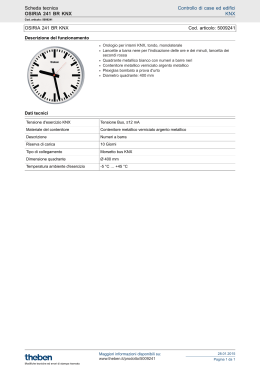
Descrizione
L’ingresso binario ekinex® EK-CA1-TP è un apparecchio KNX S-mode modulare per montaggio a
quadro per il collegamento al bus di comandi e sensori di tipo tradizionale (non comunicanti in modo
nativo sul bus KNX) dotati di contatti privi di potenziale. In questo modo, per mezzo dell’ingresso è
possibile comandare e controllare funzioni bus KNX
per mezzo di normali interruttori, pulsanti e sensori
o segnali binari messi a disposizione da altri dispositivi. L’apparecchio può essere utilizzato in configurazione da:
-- 8 canali indipendenti, ad esempio per il collegamento di interruttori o pulsanti tradizionali dedicati al comando on/off di utenze;
-- 4 canali indipendenti, ad esempio per il collegamento di doppi pulsanti per il controllo di dimmer
o azionamenti motorizzati.
L’apparecchio è dotato di un modulo di comunicazione bus integrato ed è realizzato per montaggio a
quadro su guida profilata. Per il suo funzionamento l’apparecchio riceve un segnale in ingresso e lo
traduce in un corrispondente telegramma che invia
sul bus; il telegramma viene ricevuto ed eseguito da
uno o più attuatori KNX. L’apparecchio è alimentato
a tensione SELV 30 Vdc per mezzo del bus KNX e
non richiede alimentazione ausiliaria. La tensione di
interrogazione dei canali di ingresso viene prodotta
all’interno dell’apparecchio.
Principali caratteristiche
Ogni canale di ingresso dell’apparecchio può essere programmato per svolgere una diversa funzione:
• comando on/off di utenze singole e a gruppi;
• rilevamento dello stato di contatti di segnalazione
(da apparecchi di sicurezza, allarmi, ecc.);
• richiamo e memorizzazione di scenari;
• invio sul bus di valori (temperatura, luminosità,
ecc.);
• commutazione in funzionamento forzato (blocco);
• conteggio di impulsi e di azionamenti.
Inoltre ogni coppia di canali di ingresso può essere
programmata per:
• dimmerazione di apparecchi di illuminazione;
• controllo di azionamenti per dispositivi di ombreggiamento (come tapparelle, veneziane, tende, ecc.).
Altre caratteristiche
• Custodia in materiale plastico
• Esecuzione per montaggio su guida profilata da
35 mm (secondo EN 60715)
• Grado di protezione IP20 (apparecchio installato)
• Classificazione climatica 3K5 e meccanica 3M2
(secondo EN 50491-2)
• Classe di sovratensione III (secondo EN 606641)
• Grado di inquinamento 2 (secondo IEC 60664-1)
• Peso 145 g
• Apparecchio modulare da 4 UM (1 UM = 18 mm)
• Dimensioni 72 x 90 x 70 mm (LxHxP)
Dati tecnici
Alimentazione
• Alimentazione 30 Vdc mediante bus KNX
• Assorbimento di corrente dal bus < 13 mA
• Potenza sul bus 320 mW
Ingressi
• Numero: 8
• Tensione di interrogazione: > 11 V
• Corrente di interrogazione: > 5 mA
• Lunghezza massima del collegamento: 10 m
(con cavo di sezione 0,8 mm²)
Condizioni ambientali
• Temperatura di funzionamento: - 5 ... + 45°C
• Temperatura di stoccaggio: - 25 ... + 55°C
• Temperatura di trasporto: - 25 ... + 70°C
• Umidità relativa: 95% non condensante
Elementi di comando, segnalazione e collegamento
L’apparecchio è dotato di un pulsante e di un LED di
programmazione , di pulsanti a membrana, di LED
per l’indicazione di stato e di morsetti per il collegamento della linea bus KNX e degli ingressi.
1
2
3
1
1A 2
3
2A 4
5
3A 6
7
4A 8
9
1B 10
11
2B 12
13
3B 14
15
4B 16
1A
2A
3A
4A
1B
2B
3B
4B
Caratteristiche dei morsetto KNX
• Serraggio a molla dei conduttori
• 4 sedi conduttore per ogni polarità
• Idoneo per cavo bus KNX con conduttori unifilari
di diametro compreso fra 0,6 e 0,8 mm
• Spellatura conduttori consigliata ca. 5 mm
• Codifica cromatica: rosso = conduttore bus + (positivo), nero = conduttore bus – (negativo)
Collegamento degli ingressi
a
EK-CA1-TP
8xD.I. Dry Contacts
4
5
ca1 4can
bus KNX
6
7
8
1) Morsetti di collegamento ingressi
2) Pulsanti a membrana per funzionamento forzato degli ingressi
3) Pulsante di programmazione
4) LED di programmazione
5) Morsetto di collegamento linea bus KNX
6) Pulsante per commutazione tra funzionamento forzato e automatico
7) LED per indicazione modalità funzionamento forzato / automatico
8) LED per indicazione di stato degli ingressi
Elementi di comando
• Pulsante (3) per la commutazione fra le modalità
di funzionamento normale e programmazione
• Pulsante a membrana (7) per la commutazione
fra le modalità di funzionamento forzato (pulsanti
sul frontale attivi) e automatico (pulsanti sul frontale non attivi)
• Pulsanti a membrana (2) per il funzionamento
forzato degli ingressi
La commutazione in funzionamento forzato permette di simulare lo stato dei canali di ingresso per
mezzo dei pulsanti presenti sul frontale dell’apparecchio; in questo modo è possibile testare il corretto funzionamento delle utenze da comandare prima
di collegare pulsanti o interruttori ai canali dell’ingresso binario.
i
Il collegamento degli ingressi (fig. g e h) avviene
mediante i morsetti a vite situati sul frontale dell’apparecchio nella parte superiore.
Caratteristiche dei morsetti
• Serraggio a vite dei conduttori
• Sezione max dei conduttori 2,5 mm² (rigido) o 1,5
mm² (flessibile)
• Spellatura dei conduttori consigliata ca. 6 mm
• Momento torcente max 0,8 Nm
Montaggio
L’apparecchio ha grado di protezione IP20 ed è pertanto idoneo all’impiego in ambienti interni asciutti.
La custodia è realizzata in esecuzione per montaggio su guida profilata secondo EN 60715 all’interno di quadri o di armadi di distribuzione elettrica.
Il montaggio corretto prevede che i morsetti per il
collegamento degli ingressi si trovino nella parte
superiore, il morsetto bus nella parte inferiore. Per
il montaggio dell’apparecchio procedere come segue:
• con l’ausilio di un utensile portare il dispositivo
di blocco in posizione completamente abbassata
(a);
• appoggiare l’apparecchio sul bordo superiore
della guida profilata (b)
• ruotare l’apparecchio verso la guida (c);
• spingere il dispositivo di blocco verso l’alto fino
all’arresto (d).
Per lo smontaggio dell’apparecchio, assicurarsi di
avere scollegato gli ingressi e di avere disinserito
il morsetto bus dal suo alloggiamento. Mediante un
cacciavite far scorrere verso il basso il dispositivo di
blocco e rimuovere l’apparecchio dalla guida profilata.
Marcatura
IT
Ingresso binario 8 canali
Codice: EK-CA1-TP
• KNX
• CE: il prodotto è conforme alla Direttiva Bassa Tensione (2006/95/CE) e alla Direttiva sulla
Compatibilità Elettromagnetica (2004/108/CE).
Test effettuati conformemente a EN 504912:2010, EN 50491-3:2009, EN 50491-4-1:2012,
EN 50491-5-1:2010, EN 50491-5-2:2010, EN
50428:2005 +A1:2007 + A2:2009
S
Manutenzione
L’apparecchio è privo di manutenzione. Per la sua
pulizia adoperare un panno asciutto. E’ assolutamente da evitare l’utilizzo di solventi o altre sostanze aggressive.
TP1
Foglio istruzioni
1
1A 2
3
2A 4
5
3A 6
7
4A 8
9
1B 10
11
2B 12
13
3B 14
15
4B 16
1A
2A
3A
4A
1B
2B
3B
4B
EK-CA1-TP
8xD.I. Dry Contacts
bus KNX
EK-CA1-TP
Smaltimento
b
1 1A 2
3
2A
4
5
3A
6
7
4A
8
9
1B 10
11 2B 12
13 3B 14
Il prodotto descritto nella presente
scheda tecnica al termine della sua vita
utile è classificato come rifiuto proveniente da apparecchiature elettroniche
secondo la Direttiva Europea 2002/96/
CE (RAEE), recepita in Italia con il
D.Lgs. n.151 del 25 luglio 2005, e non
può essere conferito tra i rifiuti solidi urbani indifferenziati.
15 4B 16
Collegamento come ingresso binario 8 canali (collegamento di interruttori o pulsanti tradizionali dedicati al comando
on/off di utenze)
g
L
1 1A
2
9 1B 10
c
ca1 4can
h
3 2A
4
11 2B 12
5 3A
6
7
13 3B 14
4A
8
15 4B 16
Collegamento come ingresso binario 4 canali (collegamento di doppi pulsanti per il controllo di dimmer o azionamenti
motorizzati)
!
Nota. In assenza di tensione sul bus, il comando delle
utenze non è possibile mediante i dispositivi collegati
all’ingresso ekinex®. E’ tuttavia ancora possibile se
i rispettivi attuatori KNX sono dotati di pulsanti o altri
dispositivi di comando manuale ed è presente la tensione di rete 230 Vac.
Elementi di segnalazione
• LED rosso (4) per l’indicazione della modalità di
funzionamento attiva per l’apparecchio (acceso
= programmazione, spento = funzionamento normale)
• LED verdi (8) per l’indicazione dello stato di commutazione dei canali di ingresso (acceso = contatto chiuso, spento = contatto aperto)
• LED rosso (7) per l’indicazione del modo di funzionamento (acceso = funzionamento forzato,
spento = funzionamento automatico)Montaggio
Al termine del download il funzionamento dell’apparecchio ritorna automaticamente in modalità normale; in questa modalità di funzionamento il LED
di programmazione è spento. L’apparecchio bus è
programmato e pronto al funzionamento.
Attenzione! Il collegamento elettrico dell’apparecchio deve essere eseguito esclusivamente da
personale qualificato. La non corretta installazione
può essere causa di folgorazione o incendio. Prima di eseguire i collegamenti elettrici, assicurarsi
di avere disattivato la tensione di rete.
Configurazione e messa in servizio
La configurazione e la messa in servizio dell’apparecchio richiedono l’utilizzo del programma ETS®
(Engineering Tool Software) V4 o versioni successive. Queste attività devono essere effettuate in
conformità al progetto dell’impianto di automazione
dell’edificio realizzato a cura di un professionista
abilitato.
d
i
Nota. Si consiglia di installare l’apparecchio in modo
da garantire sempre la piena accessibilità della parte
frontale per consentire l’azionamento dei pulsanti a
membrana.
Collegamento alla rete bus KNX
Il collegamento alla rete bus (fig. e) avviene mediante il morsetto KNX (5) compreso nella fornitura
e inserito nell’apposito alloggiamento situato sul
frontale dell’apparecchio nella parte inferiore.
1
1A 2
3
2A 4
5
3A 6
7
4A 8
9
1B 10
11
2B 12
13
3B 14
15
4B 16
1A
2A
3A
4A
1B
2B
3B
4B
EK-CA1-TP
8xD.I. Dry Contacts
bus KNX
KNX
Bus
e
+
-
Collegamento alla rete bus KNX
i
Nota. Le attività di configurazione e messa in servizio di
apparecchi KNX richiedono competenze specialistiche.
Per acquisire tali competenze è indispensabile partecipare ai corsi organizzati presso i centri di formazione certificati KNX.
Configurazione
Per la configurazione dei parametri dell’apparecchio occorre caricare nel programma ETS il corrispondente programma applicativo o l’intero database prodotti ekinex®. Per informazioni dettagliate
sulle possibilità di configurazione, consultare il manuale applicativo dell’apparecchio disponibile sul
sito www.ekinex.com.
Codice
Programma
applicativo
(## = versione)
Oggetti di
comunicazione
(nr. max)
Indirizzi
di gruppo
(nr. max)
EK-CA1-TP
APEKCA1TP##.knxprod
156
254
Messa in servizio
Per la messa in servizio dell’apparecchio sono necessarie le seguenti attività:
• eseguire i collegamenti elettrici come indicato
sopra;
• dare tensione al bus;
• commutare il funzionamento dell’apparecchio in
modalità di programmazione premendo l’apposito pulsante situato sul frontale. In questa modalità di funzionamento il LED di programmazione
è acceso;
• scaricare nell’apparecchio l’indirizzo fisico e la
configurazione mediante il programma ETS®.
!
Avvertenza! Lo smaltimento non corretto del prodotto può causare gravi danni all’ambiente e alla salute
umana. Per il corretto smaltimento informarsi sulle
modalità di raccolta e trattamento previste dalle autorità locali.
Avvertenze
• Il montaggio, il collegamento elettrico, la configurazione e la messa in servizio dell’apparecchio possono essere eseguiti esclusivamente da
personale qualificato in osservanza delle norme
tecniche applicabili e delle leggi in vigore nei rispettivi paesi
• L’impiego dell’apparecchio in applicazioni di sicurezza è escluso. Il dispositivo può tuttavia essere
utilizzato per funzioni di segnalazione ausiliaria
• L’apertura della custodia dell’apparecchio determina l’interruzione immediata del periodo di
garanzia
• In caso di manomissione, non è più garantita la
rispondenza ai requisiti essenziali delle direttive
applicabili per i quali l’apparecchio è stato certificato
• Apparecchi ekinex® KNX difettosi devono essere
restituiti al produttore al seguente indirizzo: SBS
S.p.A. Via Circonvallazione s/n, I-28010 Miasino
(NO)
Altre informazioni di utilità
• Il foglio istruzioni deve essere consegnato al
cliente finale insieme alla documentazione di
progetto
• Per maggiori informazioni sul prodotto è possibile
rivolgersi al supporto tecnico ekinex® all’indirizzo
e-mail: [email protected] o consultare il sito
internet www.ekinex.com
• ekinex® è un marchio registrato da SBS S.p.A.
• KNX® ed ETS® sono marchi registrati da KNX Association cvba, Bruxelles
© SBS S.p.A. 2014. La società si riserva la facoltà di apportare modifiche alla presente documentazione tecnica senza preavviso.
è un marchio registrato da
SBS S.p.A.
SEDE
Via Circonvallazione s/n
I-28010 Miasino (NO)
Tel. 0321 980909
Fax 0321 980910
R&D
Via Novara 35
I-28010 Vaprio d’Agogna (NO)
Tel. 0321 966740/1
Fax 0321 966997
[email protected]
www.ekinex.com
FISPCA1XTPIEXX0
Description
The ekinex® binary input EK-CA1-TP is a S-mode
KNX modular device for rail mounting for connection to the bus of switches and sensors of conventional type (not communicating natively on the KNX
bus) equipped with potential-free contacts. In this
way, by means of the binary input is possible to
switch and control KNX bus functions with normal
switches, pushbuttons and sensors or binary signals made available by other devices. The binary
input can be used as follows:
-- 8 independent channels, for example for the
connection of traditional (not bus) switches or
pushbuttons dedicated to the switching on/off of
loads;
-- 4 independent channels, for example for the connection of traditional (not bus) pushbuttons for
the control of dimmer or motorized drives.
The device is equipped with an integrated bus
communication module and is designed for rail
mounting in distribution boards. To operate the device receives an input signal and converts it into a
corresponding telegram sent on the bus. The telegram is received and executed by one or more KNX
actuators. The device is powered by the KNX bus
line with SELV voltage 30 Vdc and requires no auxiliary power supply. The scanning voltage for the
input channels is produced inside the device.
Main characteristics
Each input channel of the device can be programmed for a different function:
• on/off switching of single loads or group of loads;
• detecting the state of signaling contacts (from safety devices, alarms, etc.);
• recalling and saving of scenes;
• sending on the bus of values (temperature,
brightness, etc.);
• switching to forced operating mode (lock);
• counting of impulses and switching cycles.
• Each pair of input channels can be furthermore
programmed for:
• dimming of lighting devices;
• controlling drives for shading devices (such as
shutters, blinds, curtains, etc.).
Other characteristics
• Housing in plastic material
• Mounting on 35 mm rail (according to EN 60715)
• Protection degree IP20 (installed device)
• Overvoltage class III (according to EN 60664-1)
• Classification climatic 3K5 and mechanical 3M2
(according to EN 50491-2)
• Pollution degree 2 (according to IEC 60664-1)
• 4 modular units (1 unit = 18 mm)
• Weight 145 g
• Dimensions 72 x 90 x 70 mm (WxHxD)
Technical data
• 30 Vdc from KNX bus line
• Current consumption from bus < 13 mA
• Power consumption 320 mW
Ingressi
• Number: 8
• Scanning voltage: > 11 V
• Scanning current: > 5 mA
• Maximal lenght of the connection cable: 10 m
(with cable section 0,8 mm²)
Environmental conditions
• Operating temperature: - 5 ... + 45°C
• Storage temperature: - 25 ... + 55°C
• Transport temperature: - 25 ... + 70°C
• Relative humidity: 95% not condensing
Switching, display and connection elements
The device is equipped with a programming pushbutton and a programming LED, membrane pushbuttons, LED for status indication and terminals
for connecting the KNX bus line and the inputs.
1
2
1
1A 2
3
2A 4
5
3A 6
7
4A 8
9
1B 10
11
2B 12
13
3B 14
15
4B 16
1A
2A
3A
4A
1B
2B
3B
4B
ca1 4can
Connection of the inputs
Maintenance
The connection of the inputs (fig. g and h) is made
with the screw terminals located at the top.
Characteristics of the terminals
• screw clamping of conductors
• maximum cross section of conductor 2.5 mm²
(single-wire) or 1.5 mm² (multi-wire)
• recommended wire stripping approx. 6 mm
• torque max 0.8 Nm
The device is maintenance-free. To clean use a dry
cloth. It must be avoided the use of solvents or other
aggressive substances.
Binary input 8-fold
Disposal
Code: EK-CA1-TP
EK-CA1-TP
8xD.I. Dry Contacts
4
1 1A 2
5
6
7
8
1) Terminal blocks for inputs
2) Pushbuttons for forced operation of the inputs
3) LED for status indication of the inputs
4) Programming pushbutton
5) Programming LED
6) Terminal block for KNX bus line
7) Pushbutton for toggling between manual and automatic operation
8) LED for indication forced / automatic operation mode
2A
4
5
3A
6
7
4A
8
9
1B 10
11 2B 12
13 3B 14
15 4B 16
Connection as a 8-channel binary input (connection of
traditional switches or pushbuttons dedicated to the on/off
switching of loads)
L
c
1 1A
Switching to the forced operation mode allows to
simulate the state of the input channels with the pushbuttons on the front panel of the device; in this
way it is possible to test the correct operation of the
coordinated loads before connecting any device to
the inputs channels.
Note. In case of failure of bus voltage, the control of
the loads is not possible with the devices connected
to the binary input. It is still possible if the coordinated
KNX actuators are equipped with pushbuttons or other
control manual devices and is present the mains voltage 230 Vac.
Display elements
• Red LED (4) for displaying the active operating
mode of the device (on = programming, off = normal operation)
• Green LEDs (8) for displaying the switching status of the input channels (on = closed contact, off
= opened contact)
• Red LED (7) for displaying the operating mode
(on = forced operation, off = automatic operation)
2
9 1B 10
ca1 4can
Switching elements
• Pushbutton (3) for switching between the normal
and programming operating mode
• Pushbutton (6) for switching between the operating modes: forced (pushbuttons on the front
panel: active) or automatic (pushbuttons on the
front panel: not active)
• Pushbuttons (2) for forced operation of the input
channels
h
3 2A
4
11 2B 12
5 3A
6
13 3B 14
7
4A
8
15 4B 16
Connection as a 4-fold binary input (connection of double
pushbuttons dedicated to the control of dimmers or drives)
!
Warning! The electrical connection of the device
can be carried out only by qualified personnel. The
incorrect installation may result in electric shock
or fire. Before making the electrical connections,
make sure the power supply has been turned off.
Configuration and commissioning
d
Before removing the device, be sure the inputs
have been disconnected and the bus terminal has
been extracted from its slot. Use a screwdriver to
slide down the locking device and remove the device from the rail.
i
Note. It is recommended that the installation of the device always ensure the full accessibility of the front side
to allow the operation of the membrane pushbuttons.
Connection of the KNX bus line
The connection of the KNX bus line is made with the
terminal block (5) included in delivery and inserted
into the slot of the housing.
Mounting
The device has degree of protection IP20, and is
therefore suitable for use in dry interior rooms. The
housing is made for rail mounting according to EN
60715 in boards or cabinets for electrical distribution. The installation is in horizontal position, the
correct position is when the KNX bus terminal is
located at the bottom and the terminals for the inputs are located at the top. For the installation of the
device on the rail proceed as follows:
• with the aid of a tool bring the locking device in
the fully lowered position (a);
• place the upper edge of the rear inner profile on
the upper edge of the rail (b);
• rotate the device towards the rail (c);
• push the locking device upward until it stops (d).
1
1A 2
3
2A 4
5
3A 6
7
4A 8
9
1B 10
11
2B 12
13
3B 14
15
4B 16
1A
2A
3A
4A
1B
2B
3B
4B
EK-CA1-TP
8xD.I. Dry Contacts
bus KNX
KNX
Bus
a
3
bus KNX
g
i
At the end of its useful life the product
described in this datasheet is classified
as waste from electronic equipment in
accordance with the European Directive 2002/96/EC (WEEE), and cannot be
disposed together with the municipal
undifferentiated solid waste.
b
3
+
-
Characteristics of the KNX terminal block
• spring clamping of conductors
• 4 seats for conductors for each polarity
• terminal suitable for KNX bus cable with singlewire conductors and diameter between 0.6 and
0.8 mm
• recommended wire stripping approx. 5 mm
• color codification: red = + (positive) bus conductor, black = - (negative) bus conductor
Configuration and commissioning of the device require the use of the ETS® (Engineering Tool Software) program V4 or later releases. These activities must be carried out according to the design of
the building automation system done by a qualified
planner.
i
Note. The configuration and commissioning of KNX devices require specialized skills. To acquire these skills,
you should attend the workshops at KNX certified training centers.
Configuration
For the configuration of the device parameters the
corresponding application program or the whole
ekinex® product database must be loaded in the
ETS program. For detailed information on configuration options, refer to the application manual of the
device available on the website www.ekinex.com
Product
code
Application software
(## = release)
Communication
objects
(max nr.)
Group
adresses
(max nr.)
EK-CA1-TP
APEKCA1TP##.knxprod
156
254
Commissioning
For commissioning the device the following activities are required:
• make the electrical connections as described
above;
• turn on the bus power supply;
• switch the device operation to the programming
mode by pressing the programming pushbutton
located on the front side of the housing. In this
mode of operation, the programming LED is turned on;
• download into the device the physical address
and the configuration with the ETS® program.
At the end of the download the operation of the device automatically returns to normal mode; in this
mode the programming LED is turned off. Now the
bus device is programmed and ready for use.
Marks
• KNX
• CE: the device complies with the Low Voltage
Directive (2006/95/EC) and the Electromagnetic Compatibility Directive (2004/108/EC). Tests
carried out according to EN 50491-2:2010, EN
50491-3:2009, EN 50491-4-1:2012, EN 504915-1:2010, EN 50491-5-2:2010, EN 50428:2005
+A1:2007 + A2:2009
EN
!
S
Warning! Incorrect disposal of this product may
cause serious damage to the environment and human health. Please be informed about the correct
disposal procedures for waste collecting and processing provided by local authorities.
Other information
• The instruction sheet must be delivered to the
end customer with the project documentation
• For further information on the product, please
contact the ekinex® technical support at the email address: [email protected] or visit the
website www.ekinex.com
• ekinex® is a registered trademark of SBS S.p.A.
• KNX® and ETS® are registered trademarks of
KNX Association cvba, Brussels
© SBS S.p.A. 2014. The company reserves the right to make changes to this documentation without notice.
Instructions
1
1A 2
3
2A 4
5
3A 6
7
4A 8
9
1B 10
11
2B 12
13
3B 14
15
4B 16
1A
2A
3A
4A
1B
2B
3B
4B
EK-CA1-TP
8xD.I. Dry Contacts
bus KNX
Warnings
• Installation, electrical connection, configuration
and commissioning of the device can only be
carried out by qualified personnel in compliance
with the applicable technical standards and laws
of the respective countries
• The use of the device in security applications is
not allowed. The device may however be used
for auxiliary signaling functions
• Opening the housing of the device causes the
immediate end of the warranty period
• In case of tampering, the compliance with the essential requirements of the applicable directives,
for which the device has been certified, is no longer guaranteed
• ekinex® KNX defective devices must be returned
to the manufacturer at the following address:
SBS S.p.A. Via Circonvallazione s/n, I-28010
Miasino (NO) Italy
TP1
EK-CA1-TP
is a registered brand of
SBS S.p.A.
HQ
Via Circonvallazione s/n
I-28010 Miasino (NO)
Tel. +39 0321 980909
Fax +39 0321 980910
R&D
Via Novara 35
I-28010 Vaprio d’Agogna (NO)
Tel. +39 0321 966740/1
Fax +39 0321 966997
[email protected]
www.ekinex.com
FISPCA1XTPIEXX0
Scaricare