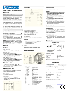
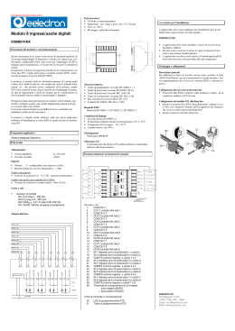
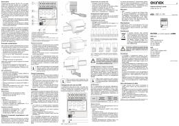
PBx0xxxKNXFI01020001.doc
Input position for
PB40CxxKNX and PB80BxxKNX
®
EELECTA KNX PUSH BUTTON
PB40BxxKNX
PB40CxxKNX
Inputs:
1.
2.
3.
4.
5.
6.
7.
8.
PB80AxxKNX
PB80BxxKNX
Product and Applications description
Eelecta® pushbutton range of KNX devices is divided in 4 different models based on the number of switch, input and
temperature sensors provided with the device.
Installation Instructions
Scheme Eelecta® pushbutton range:
Code
PB40BxxKNX
PB40CxxKNX
PB80AxKNX
PB80BxxKNX
Switch
4
4
8
8
Inputs
4
4
Input N° 4
Common
Input N° 3
Common
Common
Input N° 2
Common
Input N° 1
The device may be used for permanent indoor installations
in dry locations within wall box mounts.
Temp. Sensor
No
Yes
Yes
No
Product has 4 (8) push buttons which can be configured to
manage lights, dimmers, shutters, etc; and 4 inputs (where
present) on the backside to interface free potential contacts
(for example sensors, traditional buttons, etc.)
It has 5 white led in the front side, each led freely configurable
by ets and 2 versions have a temperature sensor included
which can be configured as a room thermostat.
The device is equipped with appropriate communication interface with the bus type TP1 (twisted pair) KNX European standard, according CEI EN 50090.
Application Program
Downloadable from eelectron website ( www.eelectron.com )
WARNING
Electrical safety
• Degree of pollution (IEC 60664-1): 2
• Degree of protection (EN 60529): IP 20
• Protection class (according to IEC 1140): III
• Overvoltage class (according to IEC 664-1): III
• Bus: safety voltage SELV DC 29 V
• Meets EN 50090 and IEC 664-1: 1992
EMC Requirements
• The device must not be connected to 230V cables
• The prevailing safety rules must be heeded.
• The device must be mounted and commissioned by an
authorised installer.
• The device must not be opened. Any faulty devices
should be returned to manufacturer.
• For planning and construction of electric installations, the
relevant guidelines, regulations and standards of the respective country are to be considered.
Mounting and Wiring hints
Compliant to EN 50081-1, EN 50082-2 and EN 50090-2.2
Terms of use
• According to EN 50090-2.2
• Ambient temperature during operation: 0 °C +4 5 °C
• Storage temperature: - 20 °C + 55 °C
• Relative humidity: max 90% (not condensing)
Maximum number of group addresses:
44
This is the maximum number of different group addresses the
device is able to memorize.
Certification
Maximum number of associations:
69
This is the maximum number of associations between communication objects and group addresses the device is able to
memorize.
CE Mark
EIB/KNX certificate
General Description
The device configuration is done by pressing the programming push button located in the back side of the housing.
Please take care during installation to leave connection
wires long enough in order to remove the device easily from
the wall box for commissioning.
Connecting bus cables
• Connect each single KNX/EIB bus core inside the terminal block observing bus polarity .
• Slip the bus connection block into the guide slot placed
on the back side of this device and press the block down
to the stop.
According to EMC guideline and low voltage directive
Indicators Position and Control Elements
Technical data
Power Supply:
Via bus EIB/KNX cable
• Voltage
• Current Consumption EIB/KNX
Switch and led position for
PB80AxxKNX and PB80BxxKNX
21..30V DC
< 10mA
Inputs
Inputs / buttons
• Switches : 4 (8 on PB80AxxKNX and PB80BxxKNX)
• Inputs
: 4 inputs for free potential contacts (on
PB40CxxKNX and PB80BxxKNX)
Note:
Note:
4 inputs for free potential contacts must connected
to dry contacts only, in particolar they can be connected to the conventional switch code
PB40AxxCON
• Maximum Cable Lenght :
• Voltage Scanning:
• Current Scanning:
≤ 10m
3,3 V dc
≤ 1 mA
Output
• Number: 5 white leds
Control Elements
• EIB/KNX led and button for physical address programming
Connections
• EIB/KNX 2 Terminals for connections bus with 0,8mmØ
• Input
4 connector cable to be wired with 24 AWG
(where present)
Switch and led position for
PB40BxxKNX and PB40CxxKNX
Mechanical Data
• Case: polycarbonate and ABS
• Protection class: II in accordance with EN 61140
• Weight: approx. 130 g
For further information please visit www.eelectron.com
eelectron spa
Via Magenta 77/22
I-20017 Rho (MI) - Italia
Email: [email protected]
Web: www.eelectron.com
PBx0xxxKNXFI01020001.doc
Posizione ingressi per versioni
PB40CxxKNX e PB80BxxKNX
Ingressi:
®
1.
2.
3.
4.
5.
6.
7.
8.
PULSANTIERA KNX EELECTA
PB40BxxKNX
PB40CxxKNX
PB80AxxKNX
PB80BxxKNX
Descrizione del prodotto e suo funzio
funzionamento
La serie di pulsantiere KNX Eelecta® è composta da 4 modelli
in base al numero di pulsanti disponibili, alla presenza degli
ingressi sulla parte posteriore e alla presenza del sensore di
temperatura.
Schema della gamma di pulsantiere Eelecta®:
Codice
Pulsanti
Ingressi
Sensore temp.
4
NO
PB40BxxKNX
4
4
SI
PB40CxxKNX
8
SI
PB80AxKNX
8
4
NO
PB80BxxKNX
Il prodotto è dotato di 4 (8) pulsanti che possono essere configurati per la gestione di luci, tapparelle, dimmer, etc.. , oltre a
4 ingressi (nelle versioni che lo prevedono)posti nella parte
posteriore e dedicati all’interfacciamento di contatti liberi da
potenziale (puliti – per esempio sensori, pulsanti tradizionali,
etc.)
Sono inoltre presenti 5 led bianchi,ciascuno liberamente configurabile con ets. Due versioni includono un sensore di temperatura che può anche essere configurato come termostato.
Il dispositivo è dotato di opportuna interfaccia di comunicazione con il bus tipo TP1 (coppia intrecciata) a standard europeo
KNX conforme alle normative di settore CEI EN 50090.
Programma applicativo
Numero massimo indirizzi di gruppo:
44
Corrisponde al numero massimo di indirizzi di gruppo diversi
che il dispositivo è in grado di memorizzare.
Numero massimo associazioni:
69
Corrisponde al numero massimo di associazioni tra oggetti di
comunicazione e indirizzi di gruppo che il dispositivo può memorizzare.
Alimentazione
Attraverso il cavo EIB/KNX
• Tensione
• Corrente assorbita EIB/KNX
Note:
Note:
L’apparecchio deve essere impiegato per installazione in
ambienti chiusi e asciutti.
IMPORTANTE
Sicurezza elettrica
•
•
•
•
•
•
Grado di inquinamento (secondo IEC 60664-1): 2
Grado di protezione (secondo EN 60529): IP 20
Classe di protezione (secondo IEC 1140): III
Classe di sovratensione (secondo IEC 664-1): III
Bus: tensione di sicurezza SELV DC 29 V
Soddisfa EN 50090 e IEC 664-1: 1992
• L’apparecchio non deve essere connesso per nessun
motivo alla tensione si rete (230V)!
• L’apparecchio deve essere installato e messo in servizio
da un installatore abilitato.
• Devono essere osservate le norme in vigore in materia di
sicurezza e prevenzione antinfortunistica.
• L’apparecchio non deve essere aperto. Eventuali apparecchi difettosi devono essere fatti pervenire alla sede
competente.
Requisiti EMC
Rispettati EN 50081-1, EN 50082-2 e EN 50090-2.2
Condizioni di impiego
•
•
•
•
Secondo norma EN 50090-2.2
Temperatura ambiente durante il funzionamento: 0°C + 45°C
Temperatura di stoccaggio: - 20 + 55 °C
Umidità relativa: max 90 %
Omologato EIB/KNX
Marcatura CE
Conformemente alla direttiva CE (edilizia abitativa e industriale), direttiva sulla bassa tensione
Montaggio e collegamento
Descrizione generale
Per effettuare la messa in servizio occorre poter accedere al
tasto “KNX/EIB” per la commutazione tra modo normale e
modo programmazione.
Collegamento del modulo alla linea bus
• Inserire il morsetto Bus EIB, precedentemente collegato
al cavo bus, nel connettore maschio che si trova sul retro
del dispositivo, fino all’arresto
• Il morsetto Bus EIB (compreso nella fornitura) è adatto
ad un conduttore unifilare con ∅ 0.8 mm
Posizione indicatori ed elementi di co
comando
Pulsanti e led per versioni
PB80AxxKNX e PB80BxxKNX
Dati tecnici
Ingressi
• Pulsanti
• Ingressi
Avvertenze
Avvertenze per l‘installazione
Omologazione
Scaricabile dal sito eelectron ( www.eelectron.com )
Ingresso N° 4
Comune
Ingresso N° 3
Comune
Comune
Ingresso N° 2
Comune
Ingresso N° 1
21..30V DC
< 10mA
: 4 (8 per PB80AxxKNX and PB80BxxKNX)
: 4 per contatti liberi da potenziale (per
PB40CxxKNX e PB80BxxKNX)
i 4 ingressi per contatti liberi da potenziale devono
essere connessi esclusivamente a contatti “puliti”,in
particolare possono essere connessi alla pulsantiera convenzionale cod. PB40AxxCON
• Massima lunghezza cavi:
• Tensione di scansione:
• Corrente di scansione:
≤ 10m
3,3 V dc
≤ 1 mA
Uscite
• Numero: 5 led bianchi
Elementi di comando
• LED rosso e pulsante EIB/KNX per la programmazione
dell’indirizzo fisico
Collegamenti
Collegamenti
• EIB/KNX 2 Terminali di connessione bus da 0,8mmØ
• Ingressi 4 connettore cablato con cavo da 24 AWG (nei
modelli dove sono presenti gli ingressi)
Pulsanti e led per versioni
PB40BxxKNX e PB40CxxKNX
Dati meccanici
• Custodia: in policarbonato e ABS
• Classe di protezione: II secondo la EN 61140
• Peso: ca. 130 g.
Per ulteriori informazioni visitate: www.eelectron.com
eelectron spa
Via Magenta 77/22
I-20017 Rho (MI) - Italia
Email: [email protected]
Web: www.eelectron.com
Scaricare