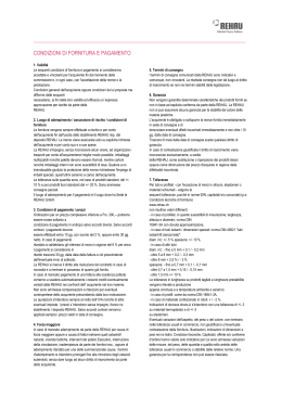
brandmanschette REHAU PLUS DE en IT montageanleitung 312666 installation instructions 312666 EN istruzioni di montaggio 312666 IT www.rehau.de Gültig ab Mai 2010 Technische Änderungen vorbehalten Construction Automotive Industry 1. Aufbaumontage Die Brandmanschette REHAU Plus ist für den sofortigen Einbau oder nachträglichen Anbau für das schalldämmende Hausabflusssystem RAUPIANO PLUS mit allgemeiner bauaufsichtllicher Zulassung Z-42.1-223 zugelassen. Die Rohrabschottung darf in mindestens 10 cm dicke Wände aus Mauerwerk, Beton bzw. Stahlbeton (DIN 1045) und leichte Trennwände in Ständerbauart mit Stahlunterkonstruktion und beidseitiger Beplankung aus Gipskarton-Feuerschutzplatten oder nichtbrennbaren Zement- bzw. Stahlbeton (DIN 1045) oder Porenbeton (DIN 4223) jeweils mindestens der Feuerwiderstandsklasse F 90 (feuerbeständig), Benennung (Kurzbezeichnung) F 90-AB, nach DIN 4102-2 eingebaut werden. Der Abstand zwischen Rohrabschottungen – gemessen zwischen den Rohren – muss bei Einbau von Rohren mit einem Rohraußendurchmesser > 160 mm mindestens 10 cm betragen. Bei kleineren Rohren dürfen die Rohrmanschetten von benachbarten Rohrabschottungen aneinander grenzen, sofern zwischen den Rohren bzw. bei eingemörtelten Manschetten zwischen den Rohrmanschetten keine Bereiche (Zwickel) vorhanden sind / entstehen, die nicht vollständig verfüllt werden können. Bei Durchführung von Rohren durch Wände sind die ersten Halterungen (Unterstützungen) der Rohre beidseitig der Wand in einem Abstand ≤ 50 cm anzuordnen. Die Halterungen müssen in Ihren wesentlichen Teilen nichtbrennbar (Baustoffklasse DIN 4102-A) sein. Bei Rohrdurchführungen durch Decken muss an der Deckenunterseite und bei Rohrdurchführungen durch Wände muss auf jeder Wandseite je eine Rohrmanschette angeordnet werden. Es muss die dem jeweiligen Rohraußendurchmesser zugeordnete Rohrmanschette verwendet werden. Vor dem Einbau der Rohrmanschette ist in jedem Fall zu kontrollieren, ob das Rohr und die Einbaubedingungen den eingangserwähnten Voraussetzungen entsprechen. 2 Montage der Schallentkopplung bei Deckeninstallation: Der mitgelieferte Schaumstoff wird um das Rohr gelegt und mittels des Klebebandes entlang des Stoßes verschlossen. Anschließend wird der Schaumstoff soweit von unten durch die Deckenöffnung geschoben, bis an der Deckenunterseite ein Überstand, der der Manschettenhöhe abzüglich max. 2 cm entspricht, stehen bleibt. Sollte der mitgelieferte Schaumstoff nicht ausreichen, kann dieser durch handelsüblichen PE-Schaumstoff (Dicke 5 mm, Brennbarkeitsklasse B2) verlängert werden. Der Zwischenraum zwischen Dämmung und Bauteil wird nun in Bauteildicke mit handelsüblichem Mörtel (MG III) verfüllt (Bild 1). Auf eine durchgängige Entkopplung des Rohres vom Bauteil ist zu achten. Weitere Vorgehensweise: siehe Montage der Brandmanschette Montage der Schallentkopplung bei Wandinstallation: Für die Wandinstallation ist je eine Manschette beidseitig der Wand erforderlich. Sofern die Wanddicke es erfordert, wird empfohlen, je einen Schaumstoffstreifen pro Seite um das Rohr zu legen, diese mit dem Klebestreifen axial zu verschließen und auf Stoß zusammenzuschieben. Um ein Eindringen von Mörtel zu vermeiden sollte diese Stoßstelle ebenfalls mit einem handelsüblichen Klebeband verschlossen werden. Der Schaumstoff wird nun so durch die Wandöffnung geschoben, dass der radiale Stoß etwa mittig in der Wand zu liegen kommt. Durch den beidseitigen Überstand wird erreicht, dass während des Verfüllens das Rohr gegen Verschmutzung geschützt wird. Sollte der mitgelieferte Schaumstoff nicht ausreichen, kann dieser durch handelsüblichen PE-Schaumstoff (Dicke 5 mm, Brennbarkeitsklasse B2) verlängert werden. Auf eine durchgängige Entkopplung des Rohres vom Bauteil ist zu achten. Der Zwischenraum zwischen Dämmung und Bauteil wird nun in Bauteildicke mit handelsüblichem Mörtel (MG III) verfüllt (Bild 2). Weitere Vorgehensweise: siehe Montage der Brandmanschette Montage der Brandmanschette: Für die Abschottung von brennbaren Rohren im Deckenbereich wird eine Manschette an der Deckenunterseite montiert, Wandabschottungen erfordern zwei Brandmanschetten, welche beidseitig der Wand installiert sind. Die Befestigungslaschen der Manschette werden mit einer Flachzange um 90° nach außen gebogen (Bild 3). Dann wird die Manschette im Bereich der Rohrdurchführung decken-/wandbündig um das Kunststoffrohr gelegt und mit Hilfe des Spannverschlusses geschlossen. Hierbei ist unbedingt darauf zu achten, dass die Federsicherung des Verschlusses einrastet. Beim Zusammenziehen muss das mit umgebogener Haltelasche versehene Blechende durch Anpressen direkt auf dem Blechende auf der Seite des Spannverschlusses aufliegen und beim Zusammenziehen darauf entlang gleiten (Bild 4). Die durch die Befestigungslaschen vorgegebene Anzahl an Bohrungen wird markiert. Zum Bohren der Löcher wird die Brandmanschette wieder entfernt (Bild 5). Die Manschette wird gegen die Wand/Decke gesetzt, verschlossen (Einrasten der Federsicherung) und mit den empfohlenen Dübeln/Schrauben (Tabelle 1) befestigt. Als weitere Sicherung wird ein Metallstift durch die Bohrungen im Spannverschluss hindurchgeführt. Es ist darauf zu achten, dass im Bereich des Manschettensitzes der Schaumstoff frei von Verunreinigungen (Mörtelreste etc.) ist. Evtl. überstehender Schaumstoffstreifen kann zum Schluss vorsichtig mit einem scharfen Messer manschettenbündig abgetrennt werden (Bild 6). Die Brandmanschette REHAU Plus kann auch an leichte Trennwände in Ständerbauart mit Stahlunterkonstruktion und ein- bzw. zweilagiger, beidseitiger Beplankung mit nichtbrennbaren zement- bzw. gipsgebundenen Bauplatten (Baustoffklasse DIN 4102-A) installiert werden, wenn diese den Bestimmungen der DIN 4102-4 für Wände der Feuerwiderstandsklasse F90 entsprechen und die Feuerwiderstandsklasse F90 durch ein Allgemeines bauaufsichtliches Prüfzeugnis nachgewiesen ist. Auf eine durchgängige Entkopplung des Rohres vom Bauteil ist zu achten. Der Ringspalt (max. 3 cm) ist zu vergipsen. Die Befestigung erfolgt mit durchgehenden Gewindestangen M6 (bis DN 75) oder M8, Muttern M6/M8 und Beilagscheiben 6,5 x 20 / 8,5 x 20 (Bild 7). Nach erfolgter Montage der Brandmanschette ist das beiliegende Kennzeichnungsschild auszufüllen und neben der Rohrabschottung an der Wand/Decke zu befestigen. Die beiliegende Übereinstimmungsbestätigung ist auszufüllen und dem Bauherrn auszuhändigen. 3 Tabelle 1: RohrBrandman- außenschette durch REHAU Plus messer (mm) Betondecken und -wände Porenbetondecken und -wände Hilti PorenbetonFischer Bolzen FBN 6/10 dübel DN 40 40 Hilti Segmentanker HSA HPD M6/10 bzw. M6x65/10/20 HPD M6/30 Hilti PorenbetonFischer Bolzen FBN 6/10 dübel DN 50 50 Hilti Segmentanker HSA HPD M6/10 bzw. M6x65/10/20 HPD M6/30 Hilti PorenbetonFischer Bolzen FBN 6/10 dübel DN 75 75 Hilti Segmentanker HSA HPD M6/10 bzw. M6x65/10/20 HPD M6/30 Fischer Ankerbolzen FAZ Hilti PorenbetonII 8/10 dübel DN 90 90 Hilti Segmentanker HSA HPD M8/10 bzw. M8x75/10/23 HPD M8/20 Fischer Ankerbolzen FAZ Hilti PorenbetonII 8/10 dübel DN 110 110 Hilti Segmentanker HSA HPD M8/10 bzw. M8x75/10/23 HPD M8/20 Fischer Ankerbolzen FAZ Hilti PorenbetonII 8/10 dübel DN 125 125 Hilti Segmentanker HSA HPD M8/10 bzw. M8x75/10/23 HPD M8/20 Fischer Ankerbolzen FAZ Hilti PorenbetonII 8/10 dübel DN 160 160 Hilti Segmentanker HSA HPD M8/10 bzw. M8x75/10/23 HPD M8/20 Fischer Ankerbolzen FAZ Hilti PorenbetonII 8/10 dübel DN 200 200 Hilti Segmentanker HSA HPD M8/10 bzw. M8x75/10/23 HPD M8/20 Beachten Sie die Montagehinweise des Befestigungsmittelherstellers 4 Mauerwerkswände (Ziegel, Kalksandstein, Beton) Anzahl Befestigungslaschen der Manschette Fischer Metallspreizdübel FMD 8x60 mit Sechskant-Holzschraube 6x60 und Unterlegscheibe 6,6x12 2 Fischer Metallspreizdübel FMD 8x60 mit Sechskant-Holzschraube 6x60 und Unterlegscheibe 6,6x12 2 Fischer Metallspreizdübel FMD 8x60 mit Sechskant-Holzschraube 6x60 und Unterlegscheibe 6,6x12 3 Fischer Metallspreizdübel FMD 8x60 mit Sechskant-Holzschraube 8x60 und Unterlegscheibe 9x16 4 Fischer Metallspreizdübel FMD 8x60 mit Sechskant-Holzschraube 8x60 und Unterlegscheibe 9x16 4 Fischer Metallspreizdübel FMD 8x60 mit Sechskant-Holzschraube 8x60 und Unterlegscheibe 9x16 4 Fischer Metallspreizdübel FMD 8x60 mit Sechskant-Holzschraube 8x60 und Unterlegscheibe 9x16 4 Fischer Metallspreizdübel FMD 8x60 mit Sechskant-Holzschraube 8x60 und Unterlegscheibe 9x16 6 2. Einbaumontage Der Decken-/Wanddurchbruch sollte je nach erforderlicher Nennweite folgende Mindestöffnung besitzen: Tabelle 2: Brandmanschette Typ DN 40-50 DN 75 DN 90 DN 110 DN 125 DN 160 Mindestdurchmesser (mm) 90 120 140 160 180 220 Einbautiefe (mm) 25 +/-10 25 +/-10 35 +/-10 35 +/-10 35 +/-10 55 +/-10 Montage bei Deckeninstallation: Der mitgelieferte Schaumstoff wird um das Rohr gelegt und mittels des Klebebandes entlang des Stoßes verschlossen. Anschließend wird der Schaumstoff soweit von unten durch die Deckenöffnung geschoben, bis ein Überstand, der der Manschettenhöhe abzüglich max. 2 cm entspricht, stehen bleibt. Sollte der mitgelieferte Schaumstoff nicht ausreichen, kann dieser durch handelsüblichen PE-Schaumstoff (Dicke 5 mm, Brennbarkeitsklasse B2) verlängert werden. Die Befestigungslaschen der Manschette werden mit einer Flachzange mittig der Bohrung um 90° nach außen gebogen (Bild 8). Die Manschette wird nun lose um den Schaumstoff gelegt und soweit von unten in die Deckenöffnung geschoben, bis sie sich in den auf der Manschette markierten Einbautiefenbereich befindet. Der Schnellverschluss wird geschlossen, die Manschette fixiert sich in der vorgegebenen Lage. Auf das Einrasten der Federsicherung ist zu achten, als weitere Sicherung ist ein Metallstift durch die Bohrungen im Spannverschluss hindurchzuführen! Auf eine durchgängige Entkopplung des Rohres vom Bauteil ist zu achten. Anschließend wird der für die Fixierung notwendige Mörtel (MG III) eingebracht (Bild 9). Vor dem Einmörteln ist der genaue Sitz der Manschette nochmals zu über-prüfen! Hinweis: Die Manschette darf nicht komplett im Bauteil verschwinden. Beachten Sie den markierten zulässigen Einbautiefenbereich! Montage bei Wandinstallation: Für die Wandinstallation (auch leichte Trennwand, Voraussetzungen siehe unten) ist je eine Manschette beidseitig der Wand erforderlich. Sofern die Wanddicke es erfordert, wird empfohlen, je einen Schaumstoffstreifen pro Seite um das Rohr zu legen, mit dem Klebestreifen axial zu verschließen und auf Stoß zusammenzuschieben. Um ein Eindringen von Mörtel zu vermeiden sollte diese Stossstelle ebenfalls mit einem handelsüblichen Klebeband verschlossen werden. Der Schaumstoff wird nun so durch die Wandöffnung geschoben, dass der radiale Stoß etwa mittig in der Wand zu liegen kommt. Durch den beidseitigen Überstand wird erreicht, dass während des Verfüllens das Rohr gegen Verschmutzung geschützt wird. Sollte der mitgelieferte Schaumstoff nicht ausreichen, kann dieser durch handelsüblichen PE-Schaumstoff (Dicke 5 mm, Brennbarkeitsklasse B2) verlängert werden. Auf eine durchgängige Entkopplung des Rohres vom Bauteil ist zu achten. Die Befestigungslaschen der Manschette werden mit einer Flachzange mittig der Bohrung um 90° nach außen gebogen (Bild 8). Die Manschette wird nun lose um den Schaumstoff gelegt und soweit in die Wandöffnung geschoben, bis sie sich in den auf der Manschette markierten Einbautiefenbereich befindet. Der Schnellverschluss wird geschlossen, die Manschette fixiert sich in der vorgegebenen Lage. Auf das 5 Einrasten der Federsicherung ist zu achten, als weitere Sicherung ist ein Metallstift durch die Bohrungen im Spannverschluss hindurchzuführen! Anschließend wird der notwendige Mörtel (MG III) eingebracht (Bild 9). Vor dem Einmörteln ist der genaue Sitz der Manschette nochmals zu über-prüfen! Hinweis: Die Manschette darf nicht komplett im Bauteil verschwinden. Beachten Sie den markierten zulässigen Einbautiefenbereich! Hinweise für leichte Trennwand: Die leichten Trennwände müssen eine beidseitige Beplankung aus je zwei mindestens 12,5 mm dicken, nichtbrennbaren (Baustoffklasse DIN 4102-A) Gipskarton-Feuerschutzplatten (GFK) nach DIN 18180 haben. Der Aufbau dieser Wände muss im Übrigen den Bestimmungen von DIN 4102-4 für Wände der Feuerwiderstandsklasse F 90 aus Gipskarton-Feuerschutzplatten entsprechen. Die Brandmanschette REHAU Plus kann auch in leichte Trennwände in Ständerbauart mit Stahlunterkonstruktion und ein- bzw. zweilagiger beidseitiger Beplankung mit nichtbrennbaren zement- bzw. gipsgebundenen Bauplatten (Baustoffklasse DIN 4102-A) eingebaut werden, wenn diese den Bestimmungen der DIN 4102-4 für Wände der Feuerwiderstandsklasse F90 entsprechen und die Feuerwiderstandsklasse F90 durch ein Allgemeines bauaufsichtliches Prüfzeugnis nachgewiesen ist. Der zulässige Einbautiefenbereich ist zu beachten. Der Ringspalt (max. 3 cm) ist mit Gips auszufüllen und nach dem Einsetzen der Manschetten anschließend zu verspachteln. Auf eine durchgängige Entkopplung des Rohres vom Bauteil ist zu achten (Bild 10). Nach erfolgter Montage der Brandmanschette ist das beiliegende Kennzeichnungsschild auszufüllen und neben der Rohrabschottung an der Wand/Decke zu befestigen. Die beiliegende Übereinstimmungsbestätigung ist auszufüllen und dem Bauherrn auszuhändigen. 6 Wichtig: Diese Montageanleitung ist eine Empfehlung. Sie gilt ausschließlich für den Einbau einer oder mehrerer Manschetten des Systems „Brandmanschette REHAU Plus“. In Kombination mit anderen Abschottungssystemen können andere Abstände gelten, die den jeweiligen bauaufsichtlichen Zulassungen bzw. Prüfzeugnissen zu entnehmen sind. Die Vorgaben der Allgemeinen bauaufsichtlichen Zulassung Z-19.17-1662 (hinterlegt im Internet unter www.rehau.de) sind zusätzlich zu beachten und einzuhalten. Beachten Sie sorgfältig die zutreffenden Brandschutzvorschriften und die jeweils gültigen Bauordnungen/ Bauvorschriften insbesondere bei -- Durchdringen von Decken und Wänden -- Räumen mit besonderen/verschärften Anforderungen an vorbeugende Brandschutzmaßnahmen (nationale Vorschriften beachten) Beachten Sie die gültigen Unfallverhütungs- und Sicherheitsvorschriften bei der Installation. 1. Surface mounting The fireproofing collar REHAU Plus is approved for immediate installation or retrospective ceiling mounting for the RAUPIANO PLUS sound insulating domestic waste water system with general technical approval Z-42.1-223. The pipe section may be installed in walls of at least 10 cm in thickness made from masonry, concrete or reinforced concrete (DIN 1045) and light partitions in framework construction with steel substructures and panels on both sides made from gypsum fire-protection boards, or non-flammable cement, reinforced concrete (DIN 1045) or porous concrete (DIN 4223) each of at least fire resistance class F 90 (fire-resistant), designation F 90-AB, to DIN 4102-2. The distance between the pipe sections – measured between the pipes – when installing pipes with an external pipe diameter of > 160 mm must be at least 10 cm. In the case of smaller pipes, the collars of neighbouring pipe sections may butt onto each other, as long as no spaces exist/occur between the pipes or, in the case of bonded collars, between the pipe collars which cannot be filled completely. When feeding pipes through walls, the first pipe brackets (supports) are to be positioned on both side of the wall at a distance of ≤ 50 cm. The essential parts of the brackets must be non-flammable (building materials class DIN 4102-A). A pipe collar must be positioned on the underside of the ceiling when feeding pipes through ceilings, or on each side of the wall when feeding pipes through walls. The designated pipe collar for the external diameter of the pipe must be used in each case. Before assembling the pipe collar, a check is always to be carried out to ensure that the pipe and installation conditions meet the requirements mentioned at the start. Installation of the noise buffer for ceiling installations: Lay the supplied foam padding around the pipe and seal along the butt joint with the adhesive tape. Then push the foam padding from beneath through the opening in the ceiling until an overlap remains at the lower side of the ceiling which corresponds to the height of the collar minus max. 2 cm. If the provided foam padding is not sufficient, it may be extended by commercially available PE foam material (thickness 5 mm, flammability class B 2). Fill the interstice between the insulation and the surface to the thickness of the surface with common mortar (MG III) (Fig. 1). Continuous isolation of the pipe from the surface must be ensured. For further procedure, see Installation of the fireproofing collar. Installation of the noise buffer for wall installations: A collar is necessary at each side of the wall for wall installation. If the wall thickness permits, we recommend placing a strip of foam padding around the pipe at each side, sealing these axially with adhesive tape and pushing these together to form a butt joint. To prevent mortar from penetrating, this butt joint should also be sealed with adhesive tape. Then push the foam padding through the opening in the wall so that the radial butt joint is approximately in the middle of the wall. The overlap at both sides ensures that the pipe is protected against dirt during filling. If the provided foam padding is not sufficient, it may be extended by commercially available PE foam material (thickness 5 mm, flammability class B 2). 7 Continuous isolation of the pipe from the surface must be ensured. Fill the interstice between the insulation and the surface to the thickness of the surface with common mortar (MG III) (Fig. 2). For further procedure, see Installation of the fireproofing collar. Installation of the fireproofing collar: A collar is installed beneath the ceiling as a barrier for inflammable pipes at the ceiling. Wall barriers require two fireproofing collars installed at both sides of the wall. Bend the fastening lugs of the collar 90° outwards with flat pliers (Fig. 3). Then lay the collar around the plastic pipe at the pipe opening flush to the ceiling/wall and close using the clamp. Ensure that the spring catch of the clamp engages. When pulled together, the sheet metal end with the bent fastening lug must be pressed directly against the sheet metal end at the side with the clamp and must slide along it (Fig. 4). Mark the holes according to the number of fastening lugs. Remove the fireproofing collar to drill the holes (Fig. 5). Place the collar against the wall/ceiling, close (spring catch engages) and screw in place with the recommended plugs/screws (Table 1). Thread a metal wire through the holes in the clamp as an additional fastening. Ensure that the foam padding is free of dirt (mortar residues etc.) at the seating of the collar. Finally, any overlapping foam padding can be cut off carefully with a sharp knife flush to the collar (Fig. 6). The fireproofing collar REHAU Plus can also be installed on light partitions in framework construction with steel substructures and one or two layers of covering on each side with non-flammable building boards bound with cement or plaster (Building materials class DIN 4102-A), if these comply with the provisions of DIN 4102-4 for walls of fire resistance class F90 and if fire resistance class F90 is confirmed by a general building approval inspection certificate. 8 Continuous isolation of the pipe from the surface must be ensured. The annular gap (max 3 cm) must be plastered. The fastening is made with continuous threaded rods M6 (up to DN 75) or M8, nuts M6/M8 and washers 6.5 x 20 / 8.5 x 20 (Fig. 7). After the fireproofing collar has been installed, fill in the supplied identification plate and attach this beside the pipe barrier on the wall/ceiling. The attached confirmation of conformity is to be completed and handed out to the building owner. Table 1: Outside Fireproopipe Concrete walls/ fing collar diame- ceilings REHAU Plus ter (mm) Aircrete walls/ ceilings Hilti aircrete dowel DN 40 40 HPD M6/10 or. HPD M6/30 Hilti aircrete Fischer bolt FBN 6/10 dowel DN 50 50 Hilti stud anchor HSA HPD M6/10 or. M6x65/10/20 HPD M6/30 Hilti aircrete Fischer bolt FBN 6/10 dowel DN 75 75 Hilti stud anchor HSA HPD M6/10 or. M6x65/10/20 HPD M6/30 Fischer anchor bolt FAZ Hilti aircrete II 8/10 dowel DN 90 90 Hilti stud anchor HSA HPD M8/10 or. M8x75/10/23 HPD M8/20 Fischer anchor bolt FAZ Hilti aircrete II 8/10 dowel DN 110 110 Hilti stud anchor HSA HPD M8/10 or. M8x75/10/23 HPD M8/20 Fischer anchor bolt FAZ Hilti aircrete II 8/10 dowel DN 125 125 Hilti stud anchor HSA HPD M8/10 or. M8x75/10/23 HPD M8/20 Fischer anchor bolt FAZ Hilti aircrete II 8/10 dowel DN 160 160 Hilti stud anchor HSA HPD M8/10 or. M8x75/10/23 HPD M8/20 Fischer anchor bolt FAZ Hilti aircrete II 8/10 dowel DN 200 200 Hilti stud anchor HSA HPD M8/10 or. M8x75/10/23 HPD M8/20 Please regard the assembly instructions of the fastener manufacturer Fischer bolt FBN 6/10 Hilti stud anchor HSA M6x65/10/20 Brick walls (brick, lime sand brick, concrete) Fischer steel expansion plug FMD 8x60 with hexagonal/wood screw 6x60 and washer 6,6x12 Fischer steel expansion plug FMD 8x60 with hexagonal/wood screw 6x60 and washer 6,6x12 Fischer steel expansion plug FMD 8x60 with hexagonal/wood screw 6x60 and washer 6,6x12 Fischer steel expansion plug FMD 8x60 with hexagonal/wood screw 8x60 and washer 9x16 Fischer steel expansion plug FMD 8x60 with hexagonal/wood screw 8x60 and washer 9x16 Fischer steel expansion plug FMD 8x60 with hexagonal/wood screw 8x60 and washer 9x16 Fischer steel expansion plug FMD 8x60 with hexagonal/wood screw 8x60 and washer 9x16 Fischer steel expansion plug FMD 8x60 with hexagonal/wood screw 8x60 and washer 9x16 Number of fastening clip for the collar 2 2 3 4 4 4 4 6 9 2. Flush mounting The ceiling/wall opening should have the following minimum dimensions according to the necessary pipe diameter: Table 2: Fireproofing collar type DN 40-50 DN 75 DN 90 DN 110 DN 125 DN 160 Minimum diameter (mm) 90 120 140 160 180 220 Istallation depth (mm) 25 +/-10 25 +/-10 35 +/-10 35 +/-10 35 +/-10 55 +/-10 Installation on ceilings: Lay the supplied foam padding around the pipe and seal along the butt joint with the adhesive tape. Then push the foam padding from beneath through the opening in the ceiling until an overlap remains at the lower side of the ceiling which corresponds to the height of the collar minus max. 2 cm. If the provided foam padding is not sufficient, it may be extended by commercially available PE foam material (thickness 5 mm, flammability class B 2). Bend the fastening lugs of the collar at the middle of the hole 90° outwards with flat pliers (Fig. 8). Lay the collar loosely around the foam padding and push into the ceiling opening from below until it is located in the installation depth range marked on the collar. Close the clamp. The collar is fixed in its current position. Ensure that the spring catch engages. Thread a metal wire through the holes in the clamp as an additional fastening. Continuos isolation of the pipe from the surface must be ensured. Then fill with the mortar (MG III) necessary for fastening (Fig. 9). Before grouting, verify the correct seating of the collar again. Note: The collar must not be fully recessed in the surface. Observe the marked, permissible installation depth range. 10 Installation on walls: A collar is necessary at each side of the wall for wall installation (and light partitions, see below for conditions). If the wall thickness permits, we recommend placing a strip of foam padding around the pipe at each side, sealing these axially with adhesive tape and pushing these together to form a butt joint. To prevent mortar from penetrating, this butt joint should also be sealed with adhesive tape. Then push the foam padding through the opening in the wall so that the radial butt joint is approximately in the middle of the wall. The overlap at both sides ensures that the pipe is protected against dirt during filling. If the provided foam padding is not sufficient, it may be extended by commercially available PE foam material (thickness 5 mm, flammability class B 2). Continuous isolation of the pipe from the surface must be ensured. Bend the fastening lugs of the collar at the middle of the hole 90° outwards with flat pliers (Fig. 8). Lay the collar loosely around the foam padding and push into the ceiling opening from below until it is located in the installation depth range marked on the collar. Close the clamp. The collar is fixed in its current position. Ensure that the spring catch engages. Thread a metal wire through the holes in the clamp as an additional fastening. Then fill with the mortar (MG III) necessary for fastening (Fig. 9). Before grouting, verify the correct seating of the collar again. Note: The collar must not be fully recessed in the surface. Observe the marked, permissible installation depth range. Notes for light partitions: Light partitions must have a panel on both sides made up of 2 non-flammable (building materials class DIN 4102-A), gypsum fire-protection boards (GFK – glassreinforced plastic) of at least 12.5 mm in thickness to DIN 18180. The composition of these walls must in general satisfy the requirements of DIN 41024 for walls of fire resistance class F 90 made from gypsum fire-protection boards. The fireproofing collar REHAU Plus can also be installed on light partitions in framework construction with steel substructures and one or two layers of covering on each side with non-flammable building boards bound with cement or plaster (Building materials class DIN 4102-A), if these comply with the provisions of DIN 4102-4 for walls of fire resistance class F90 and if fire resistance class F90 is confirmed by a general building approval inspection certificate. Observe the permissible installation depth range. The annular gap (max 3 cm) must be plastered and then finished after the collars have been inserted. Continuous isolation of the pipe from the surface must be ensured (Fig. 10). After the fireproofing collar has been installed, fill in the supplied identification plate and attach this beside the pipe barrier on the wall/ceiling. The attached confirmation of conformity is to be completed and handed out to the building owner. Important: These installation instructions are recommendations. It exclusively applies to the installation of one or more collars of the system „fireproofing collar REHAU Plus“. In combination with other sealing systems there might be other distances to be considered which can be taken from the general building approvals or from the test certificates. The provisions of the German general building approval Z-19.17-1662 must also be observed and complied with. Please carefully follow the relevant fire prevention regulations as well as the applicable building regulations/building code particularly in the context of -- penetrating ceilings and walls -- rooms demanding specific/strict fire prevention measures (observe national regulation) During installation, observe the applicable accident prevention and safety regulations. 11 1. Istruzioni per il montaggio a vista Il manicotto tagliafiamma REHAU Plus può essere installato anche in un secondo momento ed è compatibile con il sistema di scarico domestico insonorizzato RAUPIANO PLUS in base all’autorizzazione generale dell’ispettorato edile Z-42.1-223. Conformemente alla normativa DIN 4102-2, la compartimentazione per tubi deve essere installata in pareti di spessore 10 cm realizzate in muratura, calcestruzzo o cemento armato e in pareti divisorie leggere prefabbricate con sottostruttura portante in acciaio e rivestimento su entrambi i lati tramite pannelli ignifughi in cartongesso oppure in calcestruzzo/cemento armato (DIN 1045) o calcestruzzo poroso (DIN 4223) con almeno classe di resistenza al fuoco F 90 (resistente al fuoco), denominazione (abbreviata) F 90-AB. In caso di montaggio di tubi con un diametro > 160 mm, la distanza tra le compartimentazioni deve essere di 10 cm (distanza tra i tubi). Se i tubi sono di piccole dimensioni, i manicotti delle compartimentazioni adiacenti devono essere disposti uno accanto all’altro, in modo che gli spazi esistenti o che si vengono a formare tra i tubi o tra i manicotti intonacati con malta possano essere riempiti (ad es. inserimento di tasselli). Per la compartimentazione del tubo a parete è necessario disporre i primi supporti del tubo stesso su entrambi i lati della parete a una distanza ≤ 50 cm. I supporti e i relativi componenti devono essere ignifughi (classe materiale DIN 4102-A). Per la compartimentazione del tubo a soffitto, installare un manicotto nella parte inferiore del soffitto; per quella a parete, installare un manicotto su ogni lato. È necessario utilizzare un manicotto adatto al diametro del tubo. 12 Prima di montare il manicotto, verificare che il tubo sia conforme e che le procedure di montaggio seguite rispettino i presupposti descritti all’inizio. Montaggio della striscia di disaccoppiamento acustico in caso di montaggio a soffitto: -- Mettere la striscia di disaccoppiamento acustico compresa nella fornitura intorno al tubo e chiuderla mediante l’adesivo lungo la giunzione. -- Inserire, quindi, la striscia di disaccoppiamento acustico nel foro dell’ele-mento strutturale (soffitto) fino ad ottenere una sporgenza sul lato inferiore. Tale sporgenza non dovrà essere inferiore al valore dell’altezza del manicotto meno 2 cm. Nel caso in cui la schiuma non sia sufficiente, prolungare la zona anche con schiuma PE disponibile in commercio (spessore 5 mm, classe di materiale da costruzione B2). -- Sigillare l’interstizio fra isolante e soffitto. A tale scopo, devono essere utilizzati materiali non infiammabili, quali ad esempio malta cementizia (MG III) disponibile in commercio, la cui applicazione deve tenere conto dello spessore del soffitto (vedere figura 1). Il disaccoppiamento del tubo deve essere continuo. Ulteriori informazioni si trovano nel capitolo “Montaggio del manicotto tagliafiamma”. Montaggio della striscia di disaccoppiamento acustico in caso di montaggio a parete: -- Per il montaggio a parete, è necessario posizionare un manicotto su ogni lato della parete. Se lo spessore della parete lo consente, raccomandiamo di mettere una striscia di disaccoppiamento acustico intorno al tubo, su entrambi i lati, fissandola con un adesivo, in modo da formare una giunzione. Per evitare la penetrazione della malta, chiudere la giunzione con adesivo disponibile in commercio. -- Inserire la striscia di disaccoppiamento acustico nel foro dell’elemento strutturale (parete) finché la giunzione si venga a trovare nel mezzo della parete. Le sporgenze su entrambi i lati impediscono che il tubo si sporchi durante il riempimento con la malta. Nel caso in cui la schiuma non sia sufficiente, prolungare la zona anche con schiuma PE disponibile in commercio (spessore 5 mm, classe di materiale da costruzione B2). -- Sigillare l’interstizio fra isolante e soffitto. A tale scopo, devono essere utilizzati materiali non infiammabili, quali ad esempio malta cementizia (MG III) disponibile in commercio, la cui applicazione deve tenere conto dello spessore della parete (vedere figura 2). Il disaccoppiamento del tubo deve essere continuo. Ulteriori informazioni si trovano nel capitolo “Montaggio del manicotto tagliafiamma”. Montaggio del manicotto tagliafiamma: -- Per la compartimentazione del tubo a soffitto, installare un manicotto sul lato inferiore del soffitto; per quella a parete, installare un manicotto su ogni lato. -- Piegare le staffette di fissaggio con una pinza verso l’esterno di ca. 90° (vedere figura 3). -- Posizionare il manicotto intorno al tubo nella zona dell’attraversamento, a filo dell’elemento strutturale (soffitto/parete) e chiuderlo utilizzando l’apposito gancio. Assicurarsi che la chiusura rapida scatti in posizione di sicurezza. Chiudendo il lato del manicotto con staffetta piegata deve realizzarsi l’incastro nell’altro lato su cui si trova il dispositivo di chiusura (vedere figura 4). -- Disporre il manicotto a filo dell’elemento strutturale (soffitto/parete) e marcare i fori in corrispondenza delle staffette. -- Realizzare i fori smontando il manicotto (vedere figura 5). -- Riposizionare il manicotto sull’elemento strutturale (soffitto/parete), chiudere il gancio di fissaggio e fissare con tasselli e viti, come indicato nella tabella 1. Per maggiore sicurezza viene inserito un perno metallico nel foro della chiusura. -- Assicurarsi che la strisca di disaccoppiamento acustico sia priva di sporcizia (per es. resti di malta). -- Rimuovere con un coltello l’eventuale sporgenza di striscia di disaccoppiamento acustico (vedere figura 6). -- Il manicotto tagliafiamma REHAU Plus può essere installato anche su pareti leggere realizzate con lastre in cartongesso non infiammabile a uno o due strati con sottostruttura in acciaio (classe di materiale da costruzione DIN 4102-A), se le pareti corrispondono ai requisiti della normativa DIN 4102-4 per pareti con resistenza al fuo F90 e se questa resistenza al fuoco è omologata da un istituto tecnico per l‘edilizia. -- Sigiliare l’interstizio fra tubo ed elemento strutturale (max. 3 cm). Il disaccopplamento del tubo dall’elemento strutturale deve essere continuo. Realizzare il fissaggio con barre filettate M6 (fino DN 75) oppure M8, dadi M6/M8 e rondelle 6,5 x 20 / 8,5 x 20 (vedere figura 7). -- Dopo il montaggio del manicotto tagliafiamma deve essere compilata la relativa targhetta a corredo della fornitura e fissata a fianco della compartimentazione alta parete e/o al soffitto. 13 Tabella 1: Manicotto tagliafiamma REHAU Plus Diametro esterno tel tubo (mm) Calcestruzzo parete/soffitto Calcestruzzo poroso parete/soffitto Pareti piene (mattone, mattoni di arenaria, calcestruzzo) Hilti Tassello per Fischer tasselli ad espansione in calcestruzzo metallo FMD 8x60 DN 40 40 poroso con vite esagonale per legno 6x60 e HPD M6/10 o rondella 6,6x12 HPD M6/30 Hilti Tassello per Fischer Ancorante FBN Fischer tasselli ad espansione in calcestruzzo 6/10 metallo FMD 8x60 DN 50 50 poroso Hilti Ancorante HSA con vite esagonale per legno 6x60 e HPD M6/10 o M6x65/10/20 rondella 6,6x12 HPD M6/30 Hilti Tassello per Fischer Ancorante FBN Fischer tasselli ad espansione in calcestruzzo 6/10 metallo FMD 8x60 DN 75 75 poroso Hilti Ancorante HSA con vite esagonale per legno 6x60 e HPD M6/10 o M6x65/10/20 rondella 6,6x12 HPD M6/30 Hilti Tassello per Fischer Ancorante FBN Fischer tasselli ad espansione in calcestruzzo 8/10 metallo FMD 8x60 DN 90 90 poroso Hilti Ancorante HSA con vite esagonale per legno 6x60 e HPD M8/10 o M8x75/10/23 rondella 9x16 HPD M8/20 Hilti Tassello per Fischer Ancorante FBN Fischer tasselli ad espansione in calcestruzzo 8/10 metallo FMD 8x60 DN 110 110 poroso Hilti Ancorante HSA con vite esagonale per legno 6x60 e HPD M8/10 o M8x75/10/23 rondella 9x16 HPD M8/20 Hilti Tassello per Fischer Ancorante FBN Fischer tasselli ad espansione in calcestruzzo 8/10 metallo FMD 8x60 DN 125 125 poroso Hilti Ancorante HSA con vite esagonale per legno 6x60 e HPD M8/10 o M8x75/10/23 rondella 9x16 HPD M8/20 Hilti Tassello per Fischer Ancorante FBN Fischer tasselli ad espansione in calcestruzzo 8/10 metallo FMD 8x60 DN 160 160 poroso Hilti Ancorante HSA con vite esagonale per legno 6x60 e HPD M8/10 o M8x75/10/23 rondella 9x16 HPD M8/20 Hilti Tassello per Fischer Ancorante FBN Fischer tasselli ad espansione in calcestruzzo 8/10 metallo FMD 8x60 DN 200 200 poroso Hilti Ancorante HSA con vite esagonale per legno 6x60 e HPD M8/10 o M8x75/10/23 rondella 9x16 HPD M8/20 La preghiamo di leggere attentamente le istruzioni di montaggio del sistema di fissaggio del produttore Fischer Ancorante FBN 6/10 Hilti Ancorante HSA M6x65/10/20 14 Numero delle linguette di fissaggio del manicotto 2 2 3 4 4 4 4 6 2. Istruzioni per il montaggio ad incasso Il foro nell’elemento strutturale (parete/soffitto) deve avere un diametro minimo, come indicato nella seguente tabella: Tabella 2: Top de manicotto tagliafiamma DN 40-50 DN 75 DN 90 DN 110 DN 125 DN 160 Diametro minimo (mm) 90 120 140 160 180 220 Profondità di incasso (mm) 25 +/-10 25 +/-10 35 +/-10 35 +/-10 35 +/-10 55 +/-10 Montaggio del manicotto tagliafiamma a soffitto: -- Mettere la striscia di disaccoppiamento acustico compresa nella fornitura intorno al tubo e chiuderla lungo la giunzione mediante adesivo. -- Inserire, quindi, la striscia di disaccoppiamento acustico nel foro dell’elemento strutturale (soffitto) fino ad ottenere una sporgenza sul lato inferiore. Tale sporgenza non dovrà essere inferiore al valore dell’altezza del manicotto meno 2 cm. Nel caso in cui la schiuma non sia sufficiente, prolungare la zona anche con schiuma PE disponibile in commercio (spessore 5 mm, classe di materiale da costruzione B2). -- Piegare le staffette di fissaggio con una pinza verso l’esterno di ca. 90° (vedere figura 8). -- Mettere il manicotto intorno alla schiuma e inserirlo nel foro del soffitto fino a raggiungere la profondità di incasso evidenziata sul manicotto e chiuderlo utilizzando l’apposito gancio. Assicurarsi che la chiusura rapida scatti in posizione di sicurezza. Per maggiore sicurezza viene inserito un perno metallico nel foro della chiusura. -- Il disaccoppiamento del tubo dall’elemento strutturale deve essere continuo. -- Inserire la malta cementizia (MG III) per fissare il manicotto (vedere figura 9). Prima del riempimento con la malta assicurarsi della posizione del manicotto! AVVERTENZA: Il manicotto non deve scomparire completamente nell’elemento strutturale. Rispettare la profondità d’incasso ammissibile! Montaggio del manicotto tagliafiamma a parete: -- Per il montaggio a parete, è necessario posizionare un manicotto su ogni lato della parete. Se lo spessore della parete lo consente, raccomandiamo di mettere una striscia di disaccoppiamento acustico intorno al tubo, su entrambi i lati, fissandola con un adesivo, in modo da formare una giunzione. Per evitare la penetrazione della malta, chiudere la giunzione con adesivo disponibile in commercio. -- Inserire la striscia di disaccoppiamento acustico nel foro dell’elemento strutturale (parete) finché la giunzione si venga a trovare nel mezzo della parete. Le sporgenze su entrambi i lati impediscono che il tubo si sporchi durante il riempimento con la malta. Nel caso in cui la schiuma non sia sufficiente, prolungare la zona anche con schiuma PE disponibile in commercio (spessore 5 mm, classe di materiale da costruzione B2). -- Il disaccoppiamento del tubo dall’elemento strutturale deve essere continuo. -- Piegare le staffette di fissaggio con una pinza verso l’esterno di ca. 90° (vedere figura 8). -- Mettere il manicotto intorno alla schiuma e inserirlo nel foro della parete fino a raggiungere la profondità di incasso evidenziata sul manicotto e chiuderlo utilizzando l’apposito gancio. Assicurarsi che la chiusura rapida scatti in posizione di sicurezza. Per maggiore sicurezza viene inserito un perno metallico nel foro della chiusura. -- Inserire la malta cementizia (MG III) per fissare il manicotto (vedere figura 9). Prima del riempimento con la malta assicurarsi della posizione del manicotto. 15 AVVERTENZA: Il manicotto non deve scomparire completamente nell’elemento strutturale. Rispettare la profondità d’incasso ammissibile! Avvertenze per pareti leggere: Le pareti divisorie leggere devono avere un rivestimento su entrambi i lati in pannelli ignifughi in cartongesso spessi almeno 12,5 mm (classe materiale DIN 4102A) secondo la normativa DIN 18180. La loro struttura deve essere conforme alle disposizioni previste dalla norma DIN 4102-4 relativa alle pareti con classe di resistenza al fuoco F 90 realizzate in pannelli di cartongesso. Il manicotto tagliafiamma REHAU Plus può essere installato anche su pareti leggere realizzate con lastre in cartongesso non infiammabile a uno o due strati con sottostruttura in acciaio (classe di materiale da costruzione DIN 4102-A), se le pareti corrispondono ai requisiti della normativa DIN 4102-4 per pareti con resistenza al fuoco F90 e se questa resistenza al fuoco è omologata da un istituto tecnico per l’edilizia. Sigillare l’interstizio fra tubo ed elemento strutturale (max. 3 cm). Il disaccoppiamento del tubo dall’elemento strutturale deve essere continuo (vedere figura 10). Dopo il montaggio del manicotto tagliafiamma deve essere compilata la relativa targhetta a corredo della fornitura e fissata a fianco della compartimentazione alla parete e/o al soffitto. 16 IMPORTANTE: Le informazioni riportate in questo documento sono da considerarsi indicative. Le istruzioni sono valide per il montaggio di un o più manicotti denominati „manicotto tagliafiamma REHAU Plus“. In combinazione con altri sistemi di compartimentazione possono variare le distanze di montaggio, che devono essere in accordo con relativa omologazione o rapporto di prova. È necessario rispettare tutte le prescrizioni dell’omologazione Z-19.17-1662 emessa dall’istituto tecnico tedesco per l’edilizia. É, inoltre, necessario rispettare tutte le normative, le leggi, le direttive e le prescrizioni internazionali e nazionali applicabili in materia di protezione antincendio, in particolare per quanto attiene: -- attraversamento di soffitti e pareti -- vani che richiedono più rigorosi requisiti per quanto riguarda la protezione antincendio. Durante le operazioni di installazione osservare tutte le norme di sicurezza e antinfortunistiche nazionali ed internazionali. Montageanleitung / Installation Instructions / Istruzioni di montaggio Technische Änderungen vorbehalten / Subject to technical modifications / Salvo modifiche tecniche 1 2 3 4 5 6 17 7 8 9 10 Die Brandmanschette REHAU Plus ist für den nachträglichen Aufbau als auch für den sofortigen Einbau für das schalldämmende Hausabflussrohr RAUPIANO PLUS mit Allgemeiner bauaufsichtlicher Zulassung Z-42.1-223 zugelassen. The fireproofing collar REHAU Plus is approved for retro-fitting and also for immediate installation for the sound-insulating domestic waste water pipe RAUPIANO PLUS with the German general building approval number Z-42.1-223. Il manicotto tagliafiamma REHAU Plus può essere installato sia durante la posa del tubo che in un momento successivo utilizzando la tubazione del sistema di scarico domestico insonorizzato e rinforzato RAUPIANO PLUS, secondo l’omologazione Z-42.1-223 emessa dall’istituto tecnico tedesco per l’edilizia. 18 Deutsch GT-Bereich Soweit ein anderer als der in der jeweils gültigen Technischen Information beschriebene Einsatzzweck vorgesehen ist, muss der Anwender Rücksprache mit REHAU nehmen und vor dem Einsatz ausdrücklich ein schriftliches Einverständnis von REHAU einholen. Sollte dies unterbleiben, so liegt der Einsatz allein im Verantwortungsbereich des jeweiligen Anwenders. Anwendung, Verwendung und Verarbeitung der Produkte stehen in diesem Fall außerhalb unserer Kontrollmöglichkeit. Sollte dennoch eine Haftung in Frage kommen, so ist diese für alle Schäden auf den Wert der von uns gelieferten und von Ihnen eingesetzten Ware begrenzt. Urheberrecht Deutsch Ansprüche aus gegebenen Garantieerklärungen erlöschen bei Einsatzzwecken, die in den Technischen Informationen nicht beschrieben sind. Die Unterlage ist urheberrechtlich geschützt. Die dadurch begründeten Rechte, insbesondere die der Übersetzung, des Nachdruckes, der Entnahme von Abbildungen, der Funksendungen, der Wiedergabe auf fotomechanischem oder ähnlichem Wege und der Speicherung in Datenverarbeitungsanlagen, bleiben vorbehalten. Englisch HIS TI Prospekt Insofar as the intended application deviates from that described in the relevant Technical Information brochure, the user must consult REHAU and must receive express written consent from REHAU before commencing this utilization. If the user fails to do so, the sole responsibility for the utilization shall lie with the individual user. In this case, the application, use and processing of products are beyond our control. Should a case of liability arise, however, this shall be limited to the value of the goods delivered by us andEnglisch used by you in all cases of damage. Urheberrecht Claims arising from granted guarantees shall become invalid in the case of intended applications that are not described in the Technical Information brochures. Italien GT This document is protected by copyright. All rights based on this are reserved. No part of this publication may be translated, reproduced or transmitted in any form or by any similar means, electronic or mechanical, photocopying, recording or otherwise, or stored in a data retrieval system. Se è previsto un impiego diverso da quelli descritti nell’Informazione Tecnica attualmente in vigore, l’utilizzatore deve contattare la REHAU e, prima dell'impiego, chiedere espressamente il nulla osta scritto della REHAU. Altrimenti l’impiego è esclusivamente a rischio dell’utilizzatore. In questi casi l’impiego, l’uso e la lavorazione dei nostri prodotti sono al di fuori delle nostre possibilità di controllo. Se nonostante tutto, dovesse sorgere una controversia su unaItalien nostra responsabilità, questa sarà limitata al valore dei prodotti da noi forniti e impiegati da Voi. Urheberrecht Diritti derivati da dichiarazioni di garanzia non sono più validi in caso d’applicazioni non descritte nelle Informazioni Tecniche. Il presente documento è coperto da copyright. E’ vietata in particolar modo la traduzione, la ristampa, lo stralcio di singole immagini, la trasmissione via etere, qualsiasi tipo di riproduzione tramite apparecchi fotomeccanici o similari nonché l’archiviazione informatica senza nostra esplicita autorizzazione. 19 REHAU VERKAUFSBÜROS AE: Dubai, Tel.: +9714 8835677, [email protected] AR: Buenos Aires, Tel.: +54 11 489860-00, [email protected] AT: Linz, Tel.: +43 732 381610-0, linz@ rehau.com Wien, Tel.: +43 2236 24684, [email protected] AU: Adelaide, Tel.+61 8 82990031, [email protected] Brisbane, Tel.: +61 7 38897522 brisbane@ rehau.com Melbourne, Tel.: +61 3 95875544, [email protected] Perth, Tel.: +61 8 94564311, [email protected] Sydney, Tel.: +61 2 87414500, sydney@ rehau.com BA: Sarajevo, Tel.: +387 33 475-500, [email protected] BE: Brüssel, Tel.: +32 16 3999-11, [email protected] BG: Soa, Tel.: +359 2 89204-71, so[email protected] BR: Arapongas, Tel.: +55 43 3152 2004, [email protected] Belo Horizonte, Tel.: +55 31 33097737, [email protected] Caxias do Sul, Tel.:+ 55 54 32146606, [email protected] Mirassol, Tel.: +55 17 32535190, [email protected] Sao Paulo, Tel.: +55 11 461339- 22, [email protected] BY: Minsk, Tel.: +375 17 2450209, [email protected] CA: Moncton, Tel.: +1 506 5382346, [email protected] Montreal, Tel.: +1 514 9050345, montreal@rehau. com St. John‘s, Tel.: +1 709 7473909, [email protected] Toronto, Tel.: +1 905 3353284, [email protected] Vancouver, Tel.: +1 604 6264666, vancouver@ rehau.com Winnipeg, Tel.: +1 204 6972028, [email protected] CH: Bern, Tel.: +41 31 7202-120, [email protected] Vevey, Tel.: + 41 21 94826-36, vevey@ rehau.com Zürich, Tel.: +41 44 83979-79, [email protected] CL: Santiago, Tel.: +56 2 540-1900, [email protected] CN: Guangzhou, Tel.: +86 20 87760343, [email protected] Peking, Tel.: +86 10 64282956, [email protected] Shanghai, Tel.: +86 21 63551155, [email protected] CO: Bogota, Tel.: +57 1 415 7590, [email protected] CZ: Prag, Tel.: +420 2 72190-111, [email protected] DE: Berlin, Tel.: +49 30 66766-0, [email protected] Bielefeld, Tel.: +49 521 20840-0, [email protected] Bochum, Tel.: +49 234 68903-0, [email protected] Frankfurt, Tel.: +49 6074 4090-0, [email protected] Hamburg, Tel.: +49 40 733402-100, [email protected] Leipzig, Tel.: +49 34292 82-0, [email protected] München, Tel.: +49 8102 86-0, [email protected] Nürnberg, Tel.: +49 9131 93408-0, [email protected] Stuttgart, Tel.: +49 7159 1601-0, [email protected] DK: Kopenhagen, Tel.: +45 46 7737-00, [email protected] EE: Tallinn, Tel.: +372 6 0258-50, [email protected] ES: Barcelona, Tel.: +34 93 6353-500, [email protected] Bilbao, Tel.: +34 94 45386-36, bilbao@rehau. com Madrid, Tel.: +34 91 6839425, [email protected] FI: Helsinki, Tel.: +358 9 877099-00, [email protected] FR: Agen, Tel.: +33 5536958-69, agen@rehau. com Lyon, Tel.: +33 472026-300, [email protected] Metz, Tel.: +33 3870585-00, [email protected] Paris, Tel.: +33 1 348364-50, [email protected] Rennes, Tel.: +33 2 996521-30, [email protected] GB: Glasgow, Tel.: +44 1698 50 3700, [email protected] Manchester, Tel.: +44 161 7777-400, manchester@ rehau.com Slough, Tel.: +44 1753 5885-00, [email protected] GE: Tiis, Tel.: +995 32 559909, [email protected] GR: Athen, Tel.: +30 210 6682-500, athens@ rehau.com HR: Zagreb, Tel.: +3 85 1 3444-711, [email protected] HU: Budapest, Tel.:+36 23 5307-00, [email protected] ID: Jakarta, Tel.: +62 21 89907517, [email protected] IE: Dublin, Tel.: +353 1 816502-0, [email protected] IN: Neu Delhi, Tel.: +91 11 450 44700, [email protected] Mumbai, Tel.: +91 22 67922929, [email protected] IT: Mailand, Tel.: +39 02 95941-1, [email protected] Pesaro, Tel.: +39 0721 2006-11, [email protected] Rom, Tel.: +39 06 900613-11, [email protected] Treviso, Tel.: +39 0422 7265-11, [email protected] KR: Seoul, Tel.: +82 2 5011656, [email protected] KZ: Almaty, Tel.: +7 727 394 1304, [email protected] LT: Vilnius, Tel.: +3 705 24614-00, [email protected] LV: Riga, Tel.: +3 71 67 609080, [email protected] MA: Casablanca, Tel.: +2 12522 250593, [email protected] MK: Skopje, Tel.: +3 892 2402-670, [email protected] MX: Celaya, Tel.: +52 461 61880-00, [email protected] Monterrey, Tel.: +52 81 81210-130, [email protected] NL: Nijkerk, Tel.: +31 33 24799-11, [email protected] NO: Oslo, Tel.: +47 22 5141-50, [email protected] NZ: Auckland, Tel.: +64 9 2722264, [email protected] PE: Lima, Tel.: +51 1 2261713, [email protected] PL: Kattowitz, Tel.: +48 32 7755-100, [email protected] Posen, Tel.: +48 61 849-8400, [email protected] Warschau, Tel.: +48 22 2056-300, [email protected] PT: Lissabon, Tel.: +3 51 21 94972-20, [email protected] TW: Taipei, Tel.: +886 2 87803899, [email protected] RO: Bacau, Tel.: +40 234 512066, [email protected] Bukarest, Tel.: +40 21 2665180, bucuresti@rehau. com Cluj, Tel.: +40 264 415211, [email protected] RS: Belgrad, Tel.: +3 81 11 3770-301, [email protected] RU: Chabarowsk, Tel.: +7 4212 411218, [email protected] Jekaterinburg, Tel.: +7 343 2535305, [email protected] Krasnodar, Tel.: +7 861 2103636, [email protected] Moskau, Tel.: +7 495 6632060, [email protected] Nishnij Nowgorod, Phone: +7812 786927, [email protected] Nowosibirsk, Tel.: +7 383 2000353, nowosibirsk@ rehau.com Rostow am Don, Tel.: +7 8632 978444, [email protected] Samara, Tel.: +7 8462 698058, [email protected] St. Petersburg, Tel.: +7 812 3266207, [email protected] SE: Örebro, Tel.: +46 19 2064-00, [email protected] SG: Singapore, Tel.: +65 63926006, [email protected] SK: Bratislava, Tel.: +4 21 2 682091-10, [email protected] TH: Bangkok, Tel.: +66 2 7443155, [email protected] TR: Istanbul, Tel.: +90 212 35547-00, [email protected] UA: Dnepropetrowsk, Tel.: +380 56 3705028, [email protected] Kiew, Tel.: +380 44 4677710, [email protected] Lviv, Tel.: +380 32 2244810, lviv@rehau. com Odessa, Tel.: +380 48 7800708, [email protected] US: Chicago, Tel.: +1 630 3173500, [email protected] Detroit, Tel.: +1 248 8489100, detroit@rehau. com Grand Rapids, Tel.: +1 616 2856867, [email protected] Greensboro, Tel.: +1 336 8522023, [email protected] Los Angeles, Tel.: +1 951 5499017, [email protected] Minneapolis, Tel.: +1 612 253 0576, [email protected] ZA: Durban, Tel.: +27 31 657447, [email protected] Johannesburg, Tel.: +27 11 201-1300, [email protected] www.rehau.com 312666 DE, EN, IT 05.2011
Scaricare