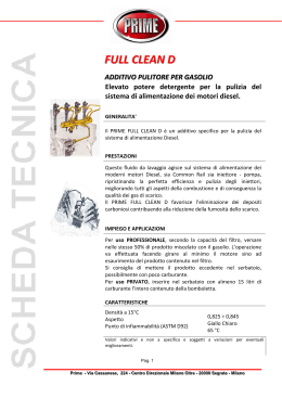
PARTS LIST
PLANEN UND ERSATZTEILLISTE
EXPLOSIETEKENINGEN EN ONDERDELEN
DIAGRAMME ET PIECES DE RECHANGE
SCHEMA E PEZZI DE RECAMBIO
LISTA DE PIEZAS
PRO 35 III
FS704T
DIESEL MODEL
DIESEL MODEL
17400 W. 119th Street
Olathe, Kansas 66061, USA
0A7853
Copyright © Jan. 28, 2002, Diamant Boart, Inc.
Printed in U.S.A.
Customer Service ........ 800-288-5040
Corporate Office .......... 913-928-1000
Cust. Service Fax ........ 800-825-0028
Corporate Office Fax ... 913-438-7951
Int’l. Fax ........................ 913-438-7938
Internet ..... http://www.targetblue.com
1
TABLE OF CONTENTS
For quick supply of spare parts and to avoid any lost time, it is essential to quote the data on the
manufacturer’s plate fixed to the machine and the part description to be replaced with every order.
DESCRIPTION .............................................................................................................................. PAGE NO.
Warnings ...................................................................................................................................................................... 8
CHASSIS GROUP
Diagram 1 - Chassis Assembly, 183803, Front Axle Assembly, 166041 ......................................................................
Diagram 2 - Rear Axle Assembly, PRO 35 Diesel, 183992 .........................................................................................
Diagram 3 - Chassis Group, PRO 35 Diesel, 183802 ................................................................................................
Diagram 4 - Transmission Group, PRO 35 Diesel, 181380 ........................................................................................
Diagram 5 - Accessory Idler Group, PRO 35 Diesel, 183818 ....................................................................................
Diagram 6 - Pointer & Sheave Guard, PRO 35 Diesel, 183804 ..................................................................................
Diagram 7 - Tie Down Kit, 167568, PRO 35 III - Optional, FS704T - Standard ...........................................................
Diagram 8 - Parking Brake Assembly, 183989, PRO 35 III - Optional, FS704T - Standard ........................................
COWL GROUP
Diagram 9 - Water Piping & Switch Group, PRO 35, 181384 ....................................................................................
Diagram 10 - Attachment Group, PRO 35 Diesel, 167458 ...........................................................................................
Diagram 11 - Electric Water Pump Group, PRO 35 Diesel, 183416, Optional .............................................................
Diagram 12 - Depth Indicator Group, 167464, Depth Stop Group, 167456 .................................................................
Diagram 13 - Fuel Line Group, PRO 35 Diesel, 183824, Fuel Tank Group, PRO 35 Diesel, 183805 ...........................
Diagram 14 - Hydraulic Pump Assembly, PRO 35 Diesel, 183411 ..............................................................................
Diagram 15 - Cowl Electrical Group, PRO 35 Diesel, 183852 .....................................................................................
Diagram 16 - Battery Bracket Group, PRO 35, 167450, Battery Group, PRO 35 Diesel, 183819 ................................
Diagram 17 - Speed Control Lever Group, PRO 35 Diesel, 183178, Handle & Switch Group, PRO 35, 183630 ..........
Diagram 18 - Control Panels: Engine & Pump, PRO 35 Diesel, 183821, Instrument Panel Assembly,
PRO 35 Diesel, 183851 .....................................................................................................................
Diagram 19 - Hardware Mounting & Cowl Weldment PRO 35, 183071 ........................................................................
Diagram 20 - Belt Guard Assembly, PRO 35 Diesel, 183811 .......................................................................................
Diagram 21 - Handle Group, PRO 35 Diesel, 164684 .................................................................................................
14
15
16
18
20
22
24
25
26
27
28
30
32
34
36
38
40
42
44
45
46
ENGINE GROUP
Diagram 22 - Air Cleaner Hose Group, PRO 35 Diesel, 183809, Air Cleaner Group, PRO 35 Diesel, 183808 ............
Diagram 23 - Engine Group, Engine Group, PRO 35 Diesel .......................................................................................
Diagram 24 - Engine Throttle Control Hardware, PRO 35 Diesel, 183822 ...................................................................
Diagram 25 - Belts & Pulleys, 18” PRO 35 Diesel, 183813 .........................................................................................
Diagram 26 - Belts & Pulleys Assembly, 26”/30” PRO 35 Diesel, 183812 ...................................................................
Diagram 27 - Bladeshaft Assembly, PRO 35 Diesel, 183636 .......................................................................................
Diagram 28 - Lift Bail Group, PRO 35 Diesel, 183817 ................................................................................................
Diagram 29 - Muffler Heat Shield Kit, 191038, PRO 35 III - Optional, FS704T - Standard ...........................................
48
50
52
53
54
56
58
59
BLADE GUARD GROUP
Diagram 30 - Attach Group, Slip-On, PRO 35, 176719 ...............................................................................................
Diagram 31 - Blade Guard Assembly - 18” Slip-On, 176635 .......................................................................................
Diagram 32 - Blade Guard Assembly - 26” Slip-On, 176645 .......................................................................................
Diagram 33 - Blade Guard Assembly - 30” Slip-On, 166911 .......................................................................................
60
62
64
66
Diagram 34 - Wiring Diagram - PRO 35 III Diesel, 182127 ........................................................................................ 68
Diagram 35 - Ladder Diagram - PRO 35 III Diesel, 182121 ........................................................................................ 70
Decals ................................................................................................................................................................. 72 - 76
Repairs and Spare Parts ............................................................................................................................................. 77
2
INHALTSVERZEICHNIS
Um eine rasche Lieferung von Ersatzteilen zu gewährleisten und Zeitverlust zu vermeiden, ist es unbedingt
erforderlich, bei jeder Bestellung die Daten auf dem Typenschild der Maschine sowie die Teilenummer des zu
ersetzenden Teiles anzugeben.
BESCHREIBUNG ....................................................................................................................... SEITENNR.
Warnungen ................................................................................................................................................................... 9
GEHÄUSEGRUPPE
Diagramm 1 - Gehäuseaggregat, 183803, Vorderachsenaggregat, 166041 ...............................................................
Diagramm 2 - Hinterachsenaggregat, PRO 35 Diesel, 183992 ..................................................................................
Diagramm 3 - Gehäusegruppe, PRO 35 Diesel, 183802 ............................................................................................
Diagramm 4 - Getriebegruppe, PRO 35 Diesel, 181380 .............................................................................................
Diagramm 5 - Hilfsriemenspannrollengruppe, PRO 35 Diesel, 183818 .......................................................................
Diagramm 6 - Einstellerzeiger und Antriebsscheibenschutz, PRO 35 Diesel, 183804 ................................................
Diagramm 7 - Verbindungsteileinbausatz, 167568, PRO 35 III – auf Wunsch erhältlich, FS704T - serienmäßig .......
Diagramm 8 - Standbremsaggregat, 183989, PRO 35 III - auf Wunsch erhältlich, FS704T - serienmäßig ................
VERKLEIDUNGSGRUPPE
Diagramm 9 - Wasserrohrleitungs- und Schaltergruppe, PRO 35, 181384 ................................................................
Diagramm 10 - Anschlussgruppe, PRO 35 Diesel, 167458 .........................................................................................
Diagramm 11 - Elektrische Wasserpumpengruppe, PRO 35 Diesel, 183416, auf Wunsch erhältlich ..........................
Diagramm 12 - Tiefenmessergruppe, 167464, Tiefenanschlaggruppe, 167456 ...........................................................
Diagramm 13 - Kraftstoffleitungsgruppe, PRO 35 Diesel, 183824, Kraftstofftankgruppe, PRO 35 Diesel, 183805 .......
Diagramm 14 - Hydraulischer Pumpenaggregat, PRO 35 Diesel, 183411 ...................................................................
Diagramm 15 - Elektrische Verkleidungsgruppe, PRO 35 Diesel, 183852 ...................................................................
Diagramm 16 - Batteriehalterungsgruppe, PRO 35, 167450, Batteriegruppe, PRO 35 Diesel, 183819 ........................
Diagramm 17 - Geschwindigkeitsregulierungshebelgruppe, PRO 35 Diesel, 183178,
Haltegriff- und Schaltergruppe, PRO 35, 183630 ..............................................................................
Diagramm 18 - Schalttafel: Motor und Pumpe, PRO 35 Diesel, 183821, Instrumententafelaggregat,
PRO 35 Diesel, 183851 .....................................................................................................................
Diagramm 19 - Kleinteilemontage und Schweißkonstruktion der Verkleidung PRO 35, 183071 ...................................
Diagramm 20 - Riemenschutzaggregat, PRO 35 Diesel, 183811 .................................................................................
Diagramm 21 - Haltegriffgruppe, PRO 35 Diesel, 164684 ...........................................................................................
MOTORGRUPPE
Diagramm 22 - Luftfilterschlauchgruppe, PRO 35 Diesel, 183809, Luftfiltergruppe, PRO 35 Diesel, 183808 ..............
Diagramm 23 - Motorgruppe, PRO 35 Diesel ..............................................................................................................
Diagramm 24 - Kleinteile für Motorenleistungsregelung, PRO 35 Diesel, 183822 ........................................................
Diagramm 25 - Riemen und Riemenscheiben, 18” PRO 35 Diesel, 183813 ................................................................
Diagramm 26 - Riemen- und Riemenscheibenaggregat, 26”/30” PRO 35 Diesel, 183812 ...........................................
Diagramm 27 - Scheibenwellenaggregat, PRO 35 Diesel, 183636 ..............................................................................
Diagramm 28 - Hubgriffgruppe, PRO 35 Diesel, 183817 .............................................................................................
Diagramm 29 - Einbausatz für Aufpuffhitzeschild, 191038, PRO 35 III - auf Wunsch erhältlich,
FS704T - serienmäßig ........................................................................................................................
SCHEIBENWELLENGRUPPE
Diagramm 30 - Anschlussgruppe, Slip-on, PRO 35, 176719 .......................................................................................
Diagramm 31 - Scheibenwellenaggregat - 18” Slip-on, 176635 ..................................................................................
Diagramm 32 - Scheibenwellenaggregat - 26” Slip-on, 176645 ..................................................................................
Diagramm 33 - Scheibenwellenaggregat - 30” Slip-on, 166911 ...................................................................................
14
15
16
18
20
22
24
25
26
27
28
30
32
34
36
38
40
42
44
45
46
48
50
52
53
54
56
58
59
60
62
64
66
Diagramm 34 - Verdrahtungsdiagramm - PRO 35 III Diesel, 182127 .......................................................................... 68
Diagramm 35 - Leiterdiagramm - PRO 35 III Diesel, 182121 ...................................................................................... 70
Aufklebeschilder .................................................................................................................................................. 72 - 76
Reparaturen und Ersatzteile ........................................................................................................................................ 77
3
INHOUD
Teneinde reserveonderdelen snel te kunnen leveren en om tijdverlies te voorkomen, is het van cruciaal belang
dat u de gegevens op het productieplaatje van de machine en de gegevens van het te vervangen onderdeel bij
iedere bestelling vermeldt.
BESCHRIJVING ........................................................................................................................ PAGINA NO.
Waarschuwingen ........................................................................................................................................................ 10
CHASSISGROEP
Diagram 1 - Chassis-samenstel, 183803, vooras-samenstel, 166041 .........................................................................
Diagram 2 - Achteras-samenstel, PRO 35 Diesel, 183992 .........................................................................................
Diagram 3 - Chassisgroep, PRO 35 Diesel, 183802 ..................................................................................................
Diagram 4 - Transmissiegroep, PRO 35 Diesel, 181380 ............................................................................................
Diagram 5 - Accessoire rolgroep, PRO 35 Diesel, 183818 ........................................................................................
Diagram 6 - Wijzer & blokschijfbescherming, PRO 35 Diesel, 183804 ......................................................................
Diagram 7 - Aansnoerk, 167568, PRO 35 III - optioneel, FS704T - standaard ...........................................................
Diagram 8 - Parkeerrem-samenstel, 183989, PRO 35 III - optioneel, FS704T - standaard ........................................
KAPGROEP
Diagram 9 - Waterleiding & Schakelgroep, PRO 35, 181384 .....................................................................................
Diagram 10 - Hulpstukkengroep, PRO 35 Diesel, 167458 ...........................................................................................
Diagram 11 - Elektrische waterpompgroep, PRO 35 Diesel, 183416, Optioneel ..........................................................
Diagram 12 - Diepte-indicatorgroep, 167464, dieptestopgroep, 167456 .....................................................................
Diagram 13 - Brandstoflijngroep, PRO 35 Diesel, 183824, brandstoftankgroep, PRO 35 Diesel, 183805 ....................
Diagram 14 - Hydraulische pompsamenstel, PRO 35 Diesel, 183411 .........................................................................
Diagram 15 - Kap elektrische groep, PRO 35 Diesel, 183852 .....................................................................................
Diagram 16 - Batterijbeugelgroep, PRO 35, 167450, Batterijgroep, PRO 35 Diesel, 183819 .......................................
Diagram 17 - Snelheidscontrolehendel-groep, PRO 35 Diesel, 183178,
Hendel & Schakelaargroep, PRO 35, 183630 .......................................................................................
Diagram 18 - Bedieningspanelen: Motor & pomp, PRO 35 Diesel, 183821, samenstel instrumentenpaneel,
PRO 35 Diesel, 183851 ........................................................................................................................
Diagram 19 - Hardwaremontage & lasconstructie kap PRO 35, 183071 ......................................................................
Diagram 20 - Riembescherming, PRO 35 Diesel, 183811 ...........................................................................................
Diagram 21 - Hendelgroep, PRO 35 Diesel, 164684 ...................................................................................................
14
15
16
18
20
22
24
25
26
27
28
30
32
34
36
38
40
42
44
45
46
MOTORGROEP
Diagram 22 - Luchtreinigerslangen-groep, PRO 35 Diesel, 183809, luchtreinigergroep, PRO 35 Diesel, 183808 .......
Diagram 23 - Motorgroep, PRO 35 Diesel ...................................................................................................................
Diagram 24 - Smoorklepregeling motor, hardware, PRO 35 Diesel, 183822 ...............................................................
Diagram 25 - Riemen & poelies, 18” PRO 35 Diesel, 183813 .....................................................................................
Diagram 26 - Riemen & poelies, samenstel, 26”/30” PRO 35 Diesel, 183812 .............................................................
Diagram 27 - Zaagspilmontage, PRO 35 Diesel, 183636 .............................................................................................
Diagram 28 - Liftbeugelgroep, PRO 35 Diesel, 183817 ...............................................................................................
Diagram 29 - Hitteschild geluiddemper, kit, 191038, PRO 35 III - optioneel, FS704T - standaard ...............................
48
50
52
53
54
56
58
59
ZAAGMESBESCHERMKAPPEN
Diagram 30 - Bevestigingsgroep, Slip-On, PRO 35, 176719 .......................................................................................
Diagram 31 - Zaagmesbeschermkap, samenstel - 18” Slip-On, 176635 ......................................................................
Diagram 32 - Zaagmesbeschermkap, samenstel - 26” Slip-On, 176645 ......................................................................
Diagram 33 - Zaagmesbeschermkap, samenstel - 30” Slip-On, 166911 ......................................................................
60
62
64
66
Diagram 34 - Bedradingsschema - PRO 35 III Diesel, 182127 ................................................................................... 68
Diagram 35 - Ladderdiagram - PRO 35 III Diesel, 182121 .......................................................................................... 70
Plakplaatjes .......................................................................................................................................................... 72 - 76
Reparaties en reserveonderdelen ............................................................................................................................... 77
4
TABLE DES MATIÈRES
Pour une distribution de pièces détachées rapide et pour éviter toute perte de temps, il est essentiel de
mentionner avec chaque commande les données de la plaque constructeur apposée sur la machine ainsi que
la description de la pièce à remplacer.
DESCRIPTION ................................................................................................................................ PAGE Nº
Avertissements ............................................................................................................................................................. 11
GROUPE CHÂSSIS
Schéma 1 - Châssis, 183803, Essieu avant, 166041 .................................................................................................
Schéma 2 - Essieu arrière, modèle Diesel PRO 35, 183992 ......................................................................................
Schéma 3 - Groupe châssis, modèle Diesel PRO 35, 183802 ...................................................................................
Schéma 4 - Groupe Transmission, modèle Diesel PRO 35, 181380 ..........................................................................
Schéma 5 - Groupe tendeur d’accessoire, modèle Diesel PRO 35, 183818 ..............................................................
Schéma 6 - Protection d’aiguille indicatrice et poulie, modèle Diesel PRO 35, 183804 ..............................................
Schéma 7 - Kit d’amarrage, 167568, PRO 35 III - Option, FS704T - Standard ..........................................................
Schéma 8 - Frein,183989, PRO 35 III - Option, FS704T - Standard ..........................................................................
GROUPE CAPOT DE PROTECTION
Schéma 9 - Groupe tuyauterie d’eau et interrupteur, PRO 35, 181384 ......................................................................
Schéma 10 - Groupe accessoires, modèle Diesel PRO 35, 167458 ...........................................................................
Schéma 11 - Groupe pompe à eau électrique, modèle Diesel PRO 35, 183416, Option ..............................................
Schéma 12 - Groupe indicateur de profondeur, 167464, Groupe butée de profondeur, 167456 .................................
Schéma 13 - Groupe conduite de carburant, modèle Diesel PRO 35, 183824, Groupe réservoir de carburant,
modèle Diesel PRO 35, 183805 ...........................................................................................................
Schéma 14 - Pompe hydraulique, modèle Diesel PRO 35, 183411 .............................................................................
Schéma 15 - Groupe électrique de capot, modèle Diesel PRO 35, 183852 ................................................................
Schéma 16 - Groupe support de batterie. PRO 35, 167450, Groupe batterie, modèle Diesel PRO 35, 183819 ...........
Schéma 17 - Groupe levier de commande de vitesse, modèle Diesel PRO 35, 183178,
Groupe poignée et interrupteur, PRO 35, 183630 .................................................................................
Schéma 18 - Panneaux de commande : Moteur et pompe, modèle Diesel PRO 35, 183821,
Panneau d’instruments, modèle Diesel PRO 35, 183851 .....................................................................
Schéma 19 - Surface soudée de montage de boulonnerie et de capot PRO 35, 183071 ............................................
Schéma 20 - Protection de courroie, modèle Diesel PRO 35, 183811 ........................................................................
Schéma 21 - Groupe poignée, modèle Diesel PRO 35, 164684 ..................................................................................
14
15
16
18
20
22
24
25
26
27
28
30
32
34
36
38
40
42
44
45
46
GROUPE MOTEUR
Schéma 22 - Groupe flexible de filtre à air, modèle Diesel PRO 35, 183809, Groupe filtre à air,
modèle Diesel PRO 35, 183808 ..........................................................................................................
Schéma 23 - Groupe moteur, modèle Diesel PRO 35 .................................................................................................
Schéma 24 - Boulonnerie de commande d’étrangleur moteur, modèle Diesel PRO 35, 183822 ..................................
Schéma 25 - Courroies et poulies, modèle Diesel PRO 35 18 po, 183813 ..................................................................
Schéma 26 - Courroies et poulies, modèle Diesel PRO 35 26 /30 po, 183812 ............................................................
Schéma 27 - Arbre de disque, modèle Diesel PRO 35, 183636 ..................................................................................
Schéma 28 - Groupe anse de levage, modèle Diesel PRO 35, 183817 .......................................................................
Schéma 29 - Kit de boucllier thermique de silencieux, 191038, PRO 35 III - Option, FS704T - Standard ...................
48
50
52
53
54
56
58
59
GROUPE PROTECTION DE DISQUE
Schéma 30 - Groupe fixations, emboîtées, PRO 35, 176719 ......................................................................................
Schéma 31 - Protection de disque - emboîtée 18 po, 176635 ....................................................................................
Schéma 32 - Protection de disque - emboîtée 26 po, 176645 ....................................................................................
Schéma 33 - Protection de disque - emboîtée 30 po, 166911 .....................................................................................
60
62
64
66
Schéma 34 - Schéma de câblage - modèle Diesel PRO 35 III, 182127 ...................................................................... 68
Schéma 35 - Schéma d’échelle - modèle Diesel PRO 35 III, 182121 .......................................................................... 70
Autocollants ......................................................................................................................................................... 72 - 76
Réparations et pièces détachées ................................................................................................................................ 77
5
INDICE
Per una rapida fornitura dei ricambi e per eliminare tempi passivi, è essenziale indicare su ogni ordine i dati
di targa del fabbricante affissi sulla macchina e la descrizione della parte di ricambio da sostituire.
DESCRIZIONE ............................................................................................................................... Pagina nº
Avvertenze .................................................................................................................................................................. 12
GRUPPO CHASSIS
Schema 1 - gruppo chassis, 183803, gruppo assale anteriore, 166041 .....................................................................
Schema 2 - gruppo assale posteriore, Diesel PRO 35, 183992 .................................................................................
Schema 3 - gruppo chassis, Diesel PRO 35, 183802 ................................................................................................
Schema 4 - gruppo trasmissione, Diesel PRO 35, 181380 ........................................................................................
Schema 5 - gruppo tenditore accessorio, Diesel PRO 35, 183818 ............................................................................
Schema 6 - protezione puntatore e puleggia scanalata, Diesel PRO 35, 183804 .......................................................
Schema 7 - kit di fissaggio, 167568, PRO 35 III - opzionale, FS704T - standard .......................................................
Schema 8 - gruppo freno a mano, 183989, PRO 35 III - opzionale, FS704T - standard ............................................
GRUPPO CAPPOTTATURA
Schema 9 - gruppo tubi acqua ed interruttori, PRO 35, 181384 .................................................................................
Schema 10 - gruppo accessori, Diesel PRO 35, 167458 ............................................................................................
Schema 11 - gruppo elettrico pompa dell’acqua, Diesel PRO 35, 183416, Opzionale .................................................
Schema 12 - gruppo indicatore di profondità, 167464, gruppo arresto di profondità, 167456 .....................................
Schema 13 - gruppo tubatura carburante, Diesel PRO 35, 183824, gruppo serbatoio carburante,
Diesel PRO 35, 183805 ........................................................................................................................
Schema 14 - gruppo pompa idraulica, Diesel PRO 35, 183411 ..................................................................................
Schema 15 - gruppo elementi elettrici della cappottatura, Diesel PRO 35, 183852 ......................................................
Schema 16 - gruppo staffa della batteria, PRO 35, 167450, gruppo della batteria, Diesel PRO 35, 183819 ................
Schema 17 - gruppo leva di controllo velocità, Diesel PRO 35, 183178, gruppo impugnature e interruttori,
PRO 35, 183630 ...................................................................................................................................
Schema 18 - quadri di comando: motore e pompa, Diesel PRO 35, 183821, gruppo quadro strumenti,
Diesel PRO 35, 183851 .......................................................................................................................
Schema 19 - montaggio bulloneria e saldatura cappottatura PRO 35, 183071 ............................................................
Schema 20 - gruppo protezione cinghia, Diesel PRO 35, 183811 ...............................................................................
Schema 21 - gruppo impugnature, Diesel PRO 35, 164684 ........................................................................................
14
15
16
18
20
22
24
25
26
27
28
30
32
34
36
38
40
42
44
45
46
GRUPPO MOTORE
Schema 22 - gruppo tubo flessibile filtro dell’aria, Diesel PRO 35, 183809, gruppo filtro dell’aria,
Diesel PRO 35, 183808 .......................................................................................................................
Schema 23 - gruppo motore, Diesel PRO 35 ..............................................................................................................
Schema 24 - bulloneria di controllo valvola a farfalla motore, Diesel PRO 35, 183822 .................................................
Schema 25 - cinghie e pulegge, Diesel PRO 35 a 18 pollici, 183813 ..........................................................................
Schema 26 - gruppo cinghie e pulegge, Diesel PRO 35 a 26/30 pollici, 183812 .........................................................
Schema 27 - gruppo albero portadisco, Diesel PRO 35, 183636 ................................................................................
Schema 28 - gruppo telaietto cernierato di alzata, Diesel PRO 35, 183817 ................................................................
Schema 29 - kit schermatura calore marmitta, 191038, PRO 35 III - opzionale, FS704T - standard ...........................
48
50
52
53
54
56
58
59
GRUPPO CARTER DEL DISCO
Schema 30 - gruppo di installazione, da infilare, PRO 35, 176719 ..............................................................................
Schema 31 - gruppo carter del disco - 18 pollici da infilare, 176635 ..........................................................................
Schema 32 - gruppo carter del disco - 26 pollici da infilare, 176645 ..........................................................................
Schema 33 - gruppo carter del disco - 30 pollici da infilare, 166911 ...........................................................................
60
62
64
66
Schema 34 - Schema impianto - Diesel PRO 35 III, 182127 ....................................................................................... 68
Schema 35 - Schema scala - Diesel PRO 35 III, 182121 ........................................................................................... 70
Etichette ............................................................................................................................................................... 72 - 76
Riparazioni e parti di ricambio .................................................................................................................................... 77
6
TABLA DE MATERIAS
Para obtener un suministro rápido de piezas de recambio (refacciones) y evitar pérdidas de tiempo, es esencial
que se mencionen en cada pedido los datos de la placa del fabricante adosada a la máquina y la descripción
de la pieza que se vaya a reemplazar.
DESCRIPCIÓN ............................................................................................................................. PÁGINA N°
Advertencias .......................................................................................................................................................................... 13
GRUPO DE CHASIS
Diagrama 1 - Ensamblaje de chasis, 183803, Conjunto de eje frontal, 166041 .................................................................... 14
Diagrama 2 - Conjunto de eje trasero, PRO 35 Diesel, 183992 ........................................................................................... 15
Diagrama 3 - Grupo de chasis, PRO 35 Diesel, 183802 ...................................................................................................... 16
Diagrama 4 - Grupo de transmisión, PRO 35 Diesel, 181380 .............................................................................................. 18
Diagrama 5 - Grupo de accesorios de piñón, PRO 35 Diesel, 183818 ................................................................................ 20
Diagrama 6 - Salvaguarda de indicador y polea, PRO 35 Diesel, 183804 ........................................................................... 22
Diagrama 7 - Juego de anclaje por debajo, 167568, PRO 35 III - Opcional, FS704T - Estándar .......................................... 24
Diagrama 8 - Ensamblaje de freno de estacionamiento, 183989, PRO 35 III - Opcional, FS704T - Estándar ....................... 25
GRUPO DE CUBIERTA DE MOTOR
Diagrama 9 - Grupo de tuberías de agua e interruptores, PRO 35, 181384 .......................................................................... 26
Diagrama 10 - Grupo de acoplamiento, PRO 35 Diesel, 167458 .......................................................................................... 27
Diagrama 11 - Grupo de bomba de agua eléctrica, PRO 35 Diesel, 183416, opcional ......................................................... 28
Diagrama 12 - Grupo de indicador de profundidad, 167464, Grupo de tope de profundidad, 167456 .................................. 30
Diagrama 13 - Grupo de tubería de combustible, PRO 35 Diesel, 183824, Depósito de combustible,
PRO 35 Diesel, 183805 ................................................................................................................................... 32
Diagrama 14 - Ensamblaje de bomba hidráulica, PRO 35 Diesel, 183411 ........................................................................... 34
Diagrama 15 - Grupo eléctrico de cubierta de motor, PRO 35 Diesel, 183852 ..................................................................... 36
Diagrama 16 - Grupo de ménsula de batería, PRO 35, 167450, Grupo de batería, PRO 35 Diesel, 183819 ........................ 38
Diagrama 17 - Grupo de palanca de control de velocidad, PRO 35 Diesel, 183178,
Grupo de mango e interruptor, PRO 35, 183630 .............................................................................................. 40
Diagrama 18 - Paneles de control: Máquina y bomba, PRO 35 Diesel, 183821,
Conjunto de panel de instrumentos, PRO 35 Diesel, 183851 .......................................................................... 42
Diagrama 19 - Tornillería de montaje y soldadura de cubierta de motor, PRO 35, 183071 .................................................... 44
Diagrama 20 - Ensamblaje de salvaguarda de banda, PRO 35 Diesel, 183811 ................................................................... 45
Diagrama 21 - Grupo de mango, PRO 35 Diesel, 164684 .................................................................................................... 46
GRUPO DE MÁQUINA
Diagrama 22 - Grupo de manguera Air Cleaner, PRO 35 Diesel, 183809, Grupo Air Cleaner,
PRO 35 Diesel, 183808 .................................................................................................................................. 48
Diagrama 23 - Grupo de máquina, PRO 35 Diesel ................................................................................................................ 50
Diagrama 24 - Dispositivos de control de acelerador de máquina, PRO 35 Diesel, 183822 ................................................. 52
Diagrama 25 - Bandas y poleas, 18” PRO 35 Diesel, 183813 .............................................................................................. 53
Diagrama 26 - Ensamblaje de bandas y poleas, 26”/30” PRO 35 Diesel, 183812 ................................................................ 54
Diagrama 27 - Ensamblaje de eje de hoja, PRO 35 Diesel, 183636 ..................................................................................... 56
Diagrama 28 - Grupo de estribo elevador, PRO 35 Diesel, 183817 ...................................................................................... 58
Diagrama 29 - Juego de protector térmico del silenciador del tubo de escape, 191038,
PRO 35 III - Opcional, FS704T - Estándar ...................................................................................................... 59
GRUPO DE SALVAGUARDA DE HOJA
Diagrama 30 - Grupo de acoplamiento, deslizable, PRO 35, 176719 ................................................................................... 60
Diagrama 31 - Ensamblaje de salvaguarda de hoja - 18” Deslizable, 176635 ....................................................................... 62
Diagrama 32 - Ensamblaje de salvaguarda de hoja - 26” Deslizable, 176645 ....................................................................... 64
Diagrama 33 - Ensamblaje de salvaguarda de hoja - 30” Deslizable, 166911 ....................................................................... 66
Diagrama 34 - Diagrama de cableado - PRO 35 III Diesel, 182127 ...................................................................................... 68
Diagrama 35 - Diagrama de escalas - PRO 35 III Diesel, 182121 ......................................................................................... 70
Calcomanías ................................................................................................................................................................... 72 - 76
Reparaciones y piezas de recambio (refacciones) ................................................................................................................ 77
7
SAFETY FIRST!!
WARNINGS
WARNING: FAILURE TO COMPLY WITH THESE WARNINGS
AND INSTRUCTIONS COULD RESULT IN DEATH OR SERIOUS INJURY.
Each machine is supplied with an operating instruction manual. Operators and
maintenance people of this equipment must read and be familiar with the
safety warnings in the operation manual. Failure to obey the warnings may
result in serious injury or death. Follow instructions strictly to ensure long
service in normal operation. If you do not have an operator’s manual (PRO 35
III: P/N 0A7846 / FS704T: P/N 0A7852), call TOLL FREE 1-800-288-5040.
Read the entire operator’s manual before operating this machine. Understand all the warnings, instructions and controls. If you do not have an
operator’s manual (PRO 35 III: P/N 0A7846 / FS704T: P/N 0A7852), call
TOLL FREE 1-800-288-5040.
Always park the machine on a level surface with the engine “OFF” and the
ignition switch set in the “OFF” position before performing any maintenance.
Let the machine cool down! Disconnect battery!
The manufacturer accepts no responsibility caused by unsuitable use or
modifications.
For repairs and service parts, contact you authorized Target dealer.
This saw was designed for certain applications only DO NOT modify this saw
or use for any application other than for which it was designed. If you have
any questions relative to its application, DO NOT use the saw until you have
contacted Diamant Boart, Inc. and we have advised you.
8
ZUERST SICHERHEIT!!
WARNUNGEN
WARNUNG: DAS NICHTBEACHTEN DIESER WARNUNGEN UND
GEBRAUCHSANLEITUNGEN KANN TOD ODER
ERNSTHAFTE KÖRPERVERLETZUNGEN ZUR FOLGE HABEN.
Jede Maschine wird mit einer Bedienungsanleitung geliefert. Das
Bedienungs- und Wartungspersonal, das an dieser Maschine arbeitet, muß
die Sicherheitswarnungen in der Bedienungsanleitung gelesen und
verstanden haben. Ein Nichtbefolgen der Warnungen kann zu schweren
Verletzungen oder Tod führen. Ein genaues Befolgen der Anleitungen wird im
normalen Einsatz eine langjährige Verwendung gewährleisten. Sollten Sie
keine Bedienungsanleitung (PRO 35 III: Bestellnummer 0A7846 / FS704T:
Bestellnummer 0A7852) haben, rufen Sie den nächsten DB/T Händler an.
Vor dem ersten Gebrauch die ganze Bedienungsanleitung durchlesen. Alle
Warnungen, Anleitungen und Bedienungskontrollen müssen gut verstanden
werden. Sollten Sie keine Bedienungsanleitung (PRO 35 III: Bestellnummer
0A7846 / FS704T: Bestellnummer 0A7852) haben, rufen Sie den nächsten
DB/T Händler an.
Vor Wartung, die Maschine auf ebener Erde mit dem Motor “ABGESTELLT”
und dem Zündschlüssel auf “AUS” abstellen. Erst die Maschine abkühlen
lassen! Den Stromkreis der Batterie unterbrechen!
Der Hersteller übernimmt keine Haftung bei unpassendem Gebrauch oder
Umbauten.
Den befugten DB/T Händler erreichen, falls Reparaturen und Ersatzteile
erforderlich sind.
Diese Maschine ist nur für bestimmte Anwendungen zugelassen. AUF
KEINEN FALL diese Maschine umändern oder zu Zwecken benutzen, die
nicht zugelassen sind. Falls Sie Fragen über eine Anwendung haben, diese
Maschine erst dann benutzen, wenn Sie an Diamant Boart/Target
geschrieben haben und wenn wir Ihre Anfrage beantwortet haben.
9
VEILIGHEID EERST !!
WAARSCHUWINGEN
WAARSCHUWING: HET NIET NALEVEN VAN DEZE WAARSCHUWINGEN EN
GEBRUIKSVOORSCHRIFTEN KAN DE DOOD OF ERNSTIGE LETSELS TOT
GEVOLG HEBBEN.
Elke machine wordt met een bedieningshandleiding geleverd. De bedieners
van deze machine en de vaklui die het onderhoud ervan uitvoeren moeten de
veiligheidswaarschuwingen in de handleiding eerst lezen en er zich vertrouwd
mee maken. Het niet naleven van de waarschuwingen kan ernstige letsels of
de dood tot gevolg hebben. Volg de voorschriften nauwkeurig zodat de machine in normale bedrijfsomstandigheden lang zou meegaan. Indien u geen
handleiding (PRO 35 III: P/N 0A7846 / FS704T: P/N 0A7852) hebt, bel dan
de DB/T verdeler op die het dichtste bij u gelegen is.
Lees eerst de gehele handleiding vooraleer deze machine te bedienen.
Begrijp al de waarschuwingen, voorschriften en het bedieningspaneel. Indien
u geen handleiding (PRO 35 III: P/N 0A7846 / FS704T: P/N 0A7852) hebt,
bel dan de DB/T verdeler op die het dichtste bij u gelegen is.
De zaagmachine altijd op een horizontaal vlak parkeren met de motor “UIT”
en de contactschakelaar in de “UIT” stand, vooraleer enig onderhoud uit te
voeren. Laat de machine afkoelen! Ontkoppel de batterij!
De fabrikant aanvaardt geen enkele verantwoordelijkheid ten gevolge van
onjuist gebruik of modificaties.
Voor herstellingen en onderhoudsonderdelen, gelieve contact op te nemen
met uw erkende DB/T verdeler.
Deze zaagmachine werd voor welbepaalde toepassingen ontworpen. Deze
zaagmachine NIET ombouwen of voor andere toepassingen gebruiken dan
degene waarvoor zij ontworpen was. Indien u enige vragen hebt betreffende
de toepassingen, de zaagmachine NIET gebruiken totdat u contact
opgenomen hebt met Diamant Boart/Target en van ons advies ontvangen
hebt.
10
SECURITE D’ABORD !!
AVERTISSEMENTS
AVERTISSEMENT : L’INOBSERVATION DE CES AVERTISSEMENTS ET INSTRUCTIONS PEUT ENTRAINER DES BLESSURES GRAVES OU MORTELLES.
Chaque machine est livrée avec un manuel d’utilisation. Les opérateurs et le
personnel d’entretien de ce matériel doivent lire et bien connaître les
consignes de sécurité figurant dans le manuel d’utilisation. L’inobservation
des avertissements peut entraîner des blessures graves ou mortelles.
Respectez scrupuleusement les instructions pour vous assurer d’une longue
durée de vie en utilisation normale. Si vous n’avez pas de manuel d’utilisation
(PRO 35 III: N/P 0A7846 / FS704T: N/P 0A7852), contactez le
concessionnaire DB/T le plus proche.
Lisez le manuel d’utilisation dans sa totalité avant d’utiliser la machine.
Assurez-vous de bien comprendre tous les avertissements, toutes les instructions ainsi que le fonctionnement des commandes. Si vous n’avez pas
de manuel d’utilisation (PRO 35 III: N/P 0A7846 / FS704T: N/P 0A7852),
contactez le concessionnaire DB/T le plus proche.
Avant d’effectuer toute opération d’entretien, garez toujours la machine sur
une surface horizontale ; ARRETEZ le moteur et mettez la clé de contact sur
la position d’ARRET (OFF). Laissez la machine refroidir ! Débranchez la
batterie !
Le fabricant ne peut être tenu pour responsable des dommages causés par
une utilisation incorrecte ou par des modifications.
Pour les réparations et les pièces de rechange, contactez votre
concessionnaire agréé DB/T.
Cette scie n’a été conçue que pour certaines applications. NE la modifiez
PAS et NE l’utilisez PAS pour des applications autres que celles pour
lesquelles elle a été conçue. Si vous avez des questions concernant son
application, N’utilisez PAS la scie avant d’avoir contacté Diamant Boart/Target et d’avoir reçu les informations nécessaires.
11
LA SICUREZZA È IMPORTANTE!!
AVVERTENZE
AVVERTENZA:IL MANCATO RISPETTO DELLE SEGUENTI AVVERTENZE E
ISTRUZIONI DI FUNZIONAMENTO PUÒ CAUSARE INCIDENTI MORTALI O
GRAVI LESIONI PERSONALI
A ciascuna macchina viene fornito di corredo un manuale d’istruzioni operative. Gli operatori e gli addetti alla manutenzione devono leggere attentamente
ed acquisire familiarità con le avvertenze di sicurezza contenute nel manuale
operativo. Il mancato rispetto delle avvertenze potrebbe causare gravi lesioni
personali e persino incidenti mortali. Per garantire che la macchina duri a
lungo in normali condizioni di utilizzo, attenersi rigorosamente alle istruzioni.
Se non si dispone di un manuale dell’operatore (PRO 35 III: N. di cat.
0A7846 / FS704T: N. di cat. 0A7852), rivolgersi al rivenditore DB/T locale.
Prima di avviare la macchina, leggere attentamente l’intero manuale
dell’operatore, e familiarizzarsi con le avvertenze, le istruzioni ed il
funzionamento dei comandi. Se non si dispone di un manuale dell’operatore
(PRO 35 III: N. di cat. 0A7846 / FS704T: N. di cat. 0A7852), rivolgersi al
rivenditore DB/T locale.
Prima di effettuare qualsiasi intervento di manutenzione, lasciare sempre la
macchina su una superficie piana con il motore spento e con l’interruttore di
accensione sulla posizione “OFF”. Lasciare che la macchina si raffreddi!
Scollegare la batteria!
Il fabbricante non si assume alcuna responsabilità per usi impropri o
modifiche non corrette.
Per eventuali interventi di riparazione e pezzi di ricambio, rivolgersi al
rivenditore DB/T locale.
Questa sega deve essere utilizzata soltanto per determinate applicazioni.
NON modificare la sega, né usarla per scopi diversi da quelli per cui è stata
progettata. In caso di dubbio in merito alle applicazioni di questa sega, NON
utilizzarla prima di essersi rivolti alla Diamant Boart/Target ed aver ricevuto
istruzioni specifiche.
12
¡SEGURIDAD ANTE TODO!
ADVERTENCAS
ADVERTENCIA: EL NO RESPETAR ESTAS ADVERTENCIAS E
INSTRUCCIONES DE OPERACION PUEDE PROVOCAR GRAVES LESIONES O
LA MUERTE.
Cada máquina se suministra con un manual de instrucciones de operación.
Los operadores y los mecánicos de este equipo deben leer y familiarizarse
con las advertencias de seguridad dadas en este manual. El no respetar las
advertencias puede provocar graves lesiones o la muerte. Siga las
instrucciones al pie de la letra para asegurar una larga vida de servicio durante operación normal. Si no tiene un manual del operador (PRO 35 III: N/P
0A7846 / FS704T: N/P 0A7852), llame a su concesionario Target más
cercano. Si se necesitan ejemplares adicionales, lammar SIN CARGO al 1800-288-5040.
Lea todo este manual y familiarícese con el funcionamiento de la máquina
antes de ponerla en marcha. Entienda todas las advertencias, instrucciones y
controles. Si no tiene un manual del operador (PRO 35 III: N/P 0A7846 /
FS704T: N/P 0A7852), llame a su concesionario Target más cercano. Si se
necesitan ejemplares adicionales, lammar SIN CARGO al 1-800-288-5040.
Siempre estacione la máquina en una superficie plana con el motor
APAGADO y el interruptor de encendido puesto en la posición APAGADO
(OFF) antes de hacer trabajos de mantenimiento en la máquina. ¡Deje que la
máquina se enfríe! ¡Desconecte la batería!
El fabricante no se hace responsable del uso o modificaciones indebidas!
Para reparaciones y piezas de repuesto, póngase en contacto con el
concesionario DB/T autorizado.
Esta sierra fue diseñada para ciertas aplicaciones solamente. NO la
modifique ni utilice para ninguna otra aplicación salvo aquéllas para las cuales
fue diseñada. En caso de dudas respecto a su aplicación, NO use la sierra
sin antes haber consultado por escrito a Diamant Boart, Inc. y haber recibido
nuestras indicaciones.
13
Diagram 1 - Chassis Assembly, 183803, Front Axle Assembly, 166041
Diagramm 1 - Gehäuseaggregat, 183803, Vorderachsenaggregat, 166041
Diagram 1 - Chassis-samenstel, 183803, vooras-samenstel, 166041
Schéma 1 - Châssis, 183803, Essieu avant, 166041
Schema 1 - gruppo chassis, 183803, gruppo assale anteriore, 166041
Diagrama 1 - Ensamblaje de chasis, 183803, Conjunto de eje frontal, 166041
DIAG.
LOC.
-2
3
14
PART
DESCRIPTION
NO.
183803 Chassis Assy, Pro35 Diesel (Complete)
183697
Frame Weldment, PRO 35
045241
Bearing, Pillow Block 1.0 Dia Bore
QTY.
REQ.
1
1
2
4
5
6
7
8
9
10
166041
163969
046402
166039
048078
043260
020551
Front Axle Assy, Pro35 (Incl. Items 5 - 10)
Front Axle Weldment, Pro35
Washer, Flat 1.031 ID x 2.00 OD x .048 Thk
Wheel, 6 Inch Dia x 2 Wide
Set Collar Assembly, 1 ID (Incl. Items 9 & 10)
Set Collar, 1 ID
Screw, Set Soc Cup Pt .312-18UNC x .25
1
1
4
2
2
1
1
11
12
13
14
020786
020365
173010
172306
Lockwasher, Split .375 Dia
Capscrew, Hex Hd .375-16UNC x 2.25
Nut, Low Hex M12 x 1.75 (7mm Tall)
Capscrew, Hex Hd M12 x 1.75 x 40mm
4
4
1
1
Diagram 2 - Rear Axle Assembly, PRO 35 Diesel, 183992
Diagramm 2 - Hinterachsenaggregat, PRO 35 Diesel, 183992
Diagram 2 - Achteras-samenstel, PRO 35 Diesel, 183992
Schéma 2 - Essieu arrière, modèle Diesel PRO 35, 183992
Schema 2 - gruppo assale posteriore, Diesel PRO 35, 183992
Diagrama 2 - Conjunto de eje trasero, PRO 35 Diesel, 183992
DIAG.
LOC.
1
2
3
4
5
6
7
8
9
10
11
12
13
PART
DESCRIPTION
NO.
183992 Rear Axle Assy, Pro35 Diesel (Incl. Items 2 - 10)
045241
Bearing, Pillow Block 1.0 Dia Bore
183987
Axle, Rear Weldment
183320
Drive Sprocket, 29 Tooth #40
139740
Capscrew, Hex Hd M6 x 1.0 x 25mm
139745
Locknut, Fiber M6 x 1.0
020071
Key, Square .250 x 2.25 Lg
166017
Wheel Assembly, (w/set screws) (Incl. Items 9 & 10)
045090
Wheel, 8 Inch Dia x 2 Wide
020531
Screw, Set Sq Hd .312-18UNC x 1.00
020786 Lockwasher, Split .375 Dia
020437 Capscrew, Hex Hd .375-16UNC x 2.50
020365 Capscrew, Hex Hd .375-16UNC x 2.25
QTY.
REQ.
1
2
1
1
6
6
2
2
1
4
4
2
2
15
Diagram 3 - Chassis Group, PRO 35 Diesel, 183802
Diagramm 3 - Gehäusegruppe, PRO 35 Diesel, 183802
Diagram 3 - Chassisgroep, PRO 35 Diesel, 183802
Schéma 3 - Groupe châssis, modèle Diesel PRO 35, 183802
Schema 3 - gruppo chassis, Diesel PRO 35, 183802
Diagrama 3 - Grupo de chasis, PRO 35 Diesel, 183802
16
Diagram 3 - Chassis Group, PRO 35 Diesel, 183802
Diagramm 3 - Gehäusegruppe, PRO 35 Diesel, 183802
Diagram 3 - Chassisgroep, PRO 35 Diesel, 183802
Schéma 3 - Groupe châssis, modèle Diesel PRO 35, 183802
Schema 3 - gruppo chassis, Diesel PRO 35, 183802
Diagrama 3 - Grupo de chasis, PRO 35 Diesel, 183802
DIAG.
LOC.
-2
3
4
5
6
7
8
9
10
11
12
13
14
15
16
17
18
19
20
21
22
23
24
25
26
27
28
29
30
31
PART
DESCRIPTION
NO.
183802 Chassis Group, Pro35 Diesel (Complete)
176604
Hydraulic Cylinder, Pro35 (Incl. Item 3)
160565
Seal Kit, Hydraulic Cylinder Pro35
020766
Washer, Flat .500 SAE
176699
Pin, Clevis .50 Dia x 2.25 Lg
020614
Pin, Cotter .125 x 1.00
176700
Pin, Clevis .50 Dia x 3.00 Lg
15700938
Fitting, Connector #4 Tube x 1/4 NPT
172017
Nut, Hex Hd M6 x 1.00
167449
Eyebolt, M6 x 50mm
167433
Bracket, Guard Mounting (metric)
173014
Washer, Flat M10
173006
Lockwasher, External Tooth, M10
139744
Capscrew, Hex Hd M10 x 1.50 x 20mm
164839
Belt Protector
139753
Capscrew, Hex Hd M8 x 1.25 x 30mm
139738
Locknut, Fiber M8 x 1.25
163132
Guide Pin
167720
Guide Swivel, M12 x 1.75
167439
Capscrew, Hex Hd M12 x 1.75 x 100mm
173010
Nut, Low Hex M12 x 1.75 (7mm Tall)
173042
Washer, Flat M12
020788
Lockwasher, Split .500 Dia
172306
Capscrew, Hex Hd M12 x 1.75 x 40mm
165744
Fitting, 45° Elbow #4 Swivel Nut
166643
Hose Assy, Depth Stop Cylinder
176725
Sprocket Assembly, 24 Teeth (Incl. Items 28 & 29)
176605
Sprocket, 24 Teeth
020550
Screw, Set Soc Cup Pt .312-18UNC x .375
020082
Key, Square .250 x 1.00 Lg
176703
Chain, #40 Roller
QTY.
REQ.
1
1
1
5
1
2
1
1
1
1
1
1
1
1
1
2
2
1
1
1
2
1
1
1
1
1
1
1
2
1
1
17
Diagram 4 - Transmission Group, PRO 35 Diesel, 181380
Diagramm 4 - Getriebegruppe, PRO 35 Diesel, 181380
Diagram 4 - Transmissiegroep, PRO 35 Diesel, 181380
Schéma 4 - Groupe Transmission, modèle Diesel PRO 35, 181380
Schema 4 - gruppo trasmissione, Diesel PRO 35, 181380
Diagrama 4 - Grupo de transmisión, PRO 35 Diesel, 181380
18
Diagram 4 - Transmission Group, PRO 35 Diesel, 181380
Diagramm 4 - Getriebegruppe, PRO 35 Diesel, 181380
Diagram 4 - Transmissiegroep, PRO 35 Diesel, 181380
Schéma 4 - Groupe Transmission, modèle Diesel PRO 35, 181380
Schema 4 - gruppo trasmissione, Diesel PRO 35, 181380
Diagrama 4 - Grupo de transmisión, PRO 35 Diesel, 181380
QTY.
REQ.
1
1
DIAG.
LOC.
-2
PART
NO.
181380
176516
Transmission Group, Pro35 Std - Diesel (Complete)
Gearbox Mtg Bracket Weldment
3
4
5
166553
046131
048326
Single Speed Gearbox Assy (Incl. Items 4 & 5)
Transmission, Hydrostatic, Eaton (Incl. Item 5)
Oil Reservoir w/Cap and O-Ring
1
1
1
6
7
8
9
10
11
12
13
14
15
16
17
18
19
20
15700950
176668
020743
139748
176531
173059
139753
139738
176533
173014
020199
176523
139750
164968
020085
Plug, Hex Hd #6 SAE
Capscrew, Hex Hd M10 x 1.50 x 120mm
Washer, Flat .375 Dia
Locknut, Fiber M10 x 1.50
Cable Bracket
Washer, Flat M8
Capscrew, Hex Hd M8 x 1.25 x 30mm
Locknut, Fiber M8 x 1.25
Speed Control Arm
Washer, Flat M10
Locknut, Fiber .375-16UNC
Tensioning Bracket
Nut, Hex Hd M10 x 1.50
Capscrew, Hex Hd M10 x 1.50 x 50mm
Key, Woodruff #404 (Flat Bottom)
2
3
3
3
1
2
2
2
1
1
1
1
1
1
1
21
22
23
176718
176535
020540
Transmission Pulley Assembly (Incl. Items 22 & 23)
Transmission Pulley
Screw, Set Soc Cup Pt .250-20UNC x .25
1
1
2
24
25
26
27
28
29
30
31
32
33
34
35
36
37
38
39
40
41
42
43
44
45
46
163040
172316
163105
172315
020776
021423
020381
176525
163689
167502
181362
020766
139022
020168
166601
020739
020612
181359
166690
181361
041427
020786
020171
Fan Attachment Plate
Locknut, Fiber M5 x 0.8
Plastic Fan Blade
Capscrew, Hex Hd M5 x 0.8 x 16mm
Lockwasher, Split .250 Dia (Hi-Collar)
Capscrew, Hex Hd .250-20UNC x .50
Capscrew, Hex Hd .250-20UNC x .875
Shift Pivot Bracket
Lockwasher, Split M6
Capscrew, Soc Hd M6 x 1.0 x 20mm
Link Shifter Assembly, Standard Pro65
Washer, Flat .500 SAE
Shoulder Bolt, .375-16UNC x .500 Shank x 1.0
Nut, Jam Hex Hd .375-16UNC
Pin, Clevis .188 Dia x 1.0
Washer, Flat #10 SAE
Pin, Cotter .094 x .75
Shifter Rod, Pro35 Std
Ball Joint, .375-24UNF RH
Grommet, 7/16ID x 11/16 Dia Hole
Knob, Black
Lockwasher, Split .375 Dia
Nut, Jam Hex Hd .375-24UNF RH
2
3
1
3
2
1
1
1
2
2
1
2
1
1
1
1
1
1
1
1
1
1
1
DESCRIPTION
19
Diagram 5 - Accessory Idler Group, PRO 35 Diesel, 183818
Diagramm 5 - Hilfsriemenspannrollengruppe, PRO 35 Diesel, 183818
Diagram 5 - Accessoire rolgroep, PRO 35 Diesel, 183818
Schéma 5 - Groupe tendeur d’accessoire, modèle Diesel PRO 35, 183818
Schema 5 - gruppo tenditore accessorio, Diesel PRO 35, 183818
Diagrama 5 - Grupo de accesorios de piñón, PRO 35 Diesel, 183818
20
Diagram 5 - Accessory Idler Group, PRO 35 Diesel, 183818
Diagramm 5 - Hilfsriemenspannrollengruppe, PRO 35 Diesel, 183818
Diagram 5 - Accessoire rolgroep, PRO 35 Diesel, 183818
Schéma 5 - Groupe tendeur d’accessoire, modèle Diesel PRO 35, 183818
Schema 5 - gruppo tenditore accessorio, Diesel PRO 35, 183818
Diagrama 5 - Grupo de accesorios de piñón, PRO 35 Diesel, 183818
DIAG.
LOC.
1
2
3
4
5
6
7
8
9
10
11
12
13
14
PART
DESCRIPTION
NO.
173042 Washer, Flat M12
020788 Lockwasher, Split .500 Dia
139741 Capscrew, Hex Hd M12 x 1.75 x 30mm
183818 Accessory Idler Group, Pro35 Diesel (Incl. Items 5 - 14)
173014
Washer, Flat M10
139750
Nut, Hex Hd M10 x 1.50
167764
Pulley Assembly, M10 Bore
183765
Idler Arm, Deutz 2 Cyl.
046101
Washer, Fiber 1.0 OD x 13/32 ID x 3/32
177064
Capscrew, Hex Hd M10 x 1.50 x 45mm
139748
Locknut, Fiber M10 x 1.50
167748
Capscrew, Hex Hd M10 x 1.50 x 65mm
163259
Spring Clip
139102
Spring, Extension .75 Dia x 4
QTY.
REQ.
1
1
1
1
3
1
1
1
2
1
2
1
1
1
21
Diagram 6 - Pointer & Sheave Guard, PRO 35 Diesel, 183804
Diagramm 6 - Einstellerzeiger und Antriebsscheibenschutz, PRO 35 Diesel, 183804
Diagram 6 - Wijzer & blokschijfbescherming, PRO 35 Diesel, 183804
Schéma 6 - Protection d’aiguille indicatrice et poulie, modèle Diesel PRO 35, 183804
Schema 6 - protezione puntatore e puleggia scanalata, Diesel PRO 35, 183804
Diagrama 6 - Salvaguarda de indicador y polea, PRO 35 Diesel, 183804
22
Diagram 6 - Pointer & Sheave Guard, PRO 35 Diesel, 183804
Diagramm 6 - Einstellerzeiger und Antriebsscheibenschutz, PRO 35 Diesel, 183804
Diagram 6 - Wijzer & blokschijfbescherming, PRO 35 Diesel, 183804
Schéma 6 - Protection d’aiguille indicatrice et poulie, modèle Diesel PRO 35, 183804
Schema 6 - protezione puntatore e puleggia scanalata, Diesel PRO 35, 183804
Diagrama 6 - Salvaguarda de indicador y polea, PRO 35 Diesel, 183804
DIAG.
LOC.
-2
3
4
5
6
7
8
9
10
11
12
13
14
15
16
17
PART
DESCRIPTION
NO.
183804 Pointer Group, Pro35, Diesel (Complete)
167453
Front Pointer Assembly (Incl. Items 3 - 8)
167423
Front Pointer Weldment, Pro35
160196
Front Pointer Rod
163582
Wheel, Front Pointer 5 Inch Dia
060735
Collar, Shaft .5 ID
173010
Nut, Low Hex M12 x 1.75 (7mm Tall)
139751
Capscrew, Hex Hd M12 x 1.75 x 25mm
167431
139742
047091
162004
164968
183933
139763
043201
043203
Capscrew, Hex Hd M12 x 1.75 x 65mm
Locknut, Fiber M12 x 1.75
Rear Pointer Weldment
Lockwasher, Split M10
Capscrew, Hex Hd M10 x 1.50 x 50mm
Flange Cover Pro 35/65
Capscrew, Hex Hd M10 x 1.50 x 100mm
Sash Cord, 1/4 Dia x 10FT
Clamp, Circle
QTY.
REQ.
1
1
1
1
1
2
2
2
2
2
1
3
1
1
2
1
3
23
Diagram 7 - Tie Down Kit, 167568, PRO 35 III - Optional, FS704T – Standard
Diagramm 7 - Verbindungsteileinbausatz, 167568, PRO 35 III – auf Wunsch erhältlich, FS704T - serienmäßig
Diagram 7 - Aansnoerk, 167568, PRO 35 III - optioneel, FS704T - standaard
Schéma 7 - Kit d’amarrage, 167568, PRO 35 III - Option, FS704T - Standard
Schema 7 - kit di fissaggio, 167568, PRO 35 III - opzionale, FS704T - standard
Diagrama 7 - Juego de anclaje por debajo, 167568, PRO 35 III - Opcional, FS704T - Estándar
24
DIAG.
LOC.
-2
3
4
5
6
PART
DESCRIPTION
NO.
167568 Tie Down Kit (Complete)
0A7667
Instruction Sheet, Tie Down Kit
163977
Tie down Chain Loop
173006
Lockwasher, External Tooth, M10
047792
Capscrew, Hex Hd M10 x 1.50 x 30mm
139748
Locknut, Fiber M10 x 1.50
QTY.
REQ.
1
1
3
6
6
4
Diagram 8 - Parking Brake Assembly, 183989, PRO 35 III - Optional, FS704T – Standard
Diagramm 8 - Standbremsaggregat, 183989, PRO 35 III - auf Wunsch erhältlich, FS704T - serienmäßig
Diagram 8 - Parkeerrem-samenstel, 183989, PRO 35 III - optioneel, FS704T - standaard
Schéma 8 - Frein,183989, PRO 35 III - Option, FS704T - Standard
Schema 8 - gruppo freno a mano, 183989, PRO 35 III - opzionale, FS704T - standard
Diagrama 8 - Ensamblaje de freno de estacionamiento, 183989, PRO 35 III - Opcional, FS704T - Estándar
DIAG.
LOC.
-2
3
4
5
6
7
8
9
10
11
12
PART
DESCRIPTION
NO.
183989 Brake Assembly Group, Pro35 (Complete)
183985
Brake Assembly Pro 35
183967
Brake Disc Pro 35
139740
Capscrew, Hex Hd M6 x 1.0 x 25mm
139745
Locknut, Fiber M6 x 1.0
178957
Bushing, 7/16ID x 11/16 Dia Hole
183975
Control Rod Pro 35
020612
Pin, Cotter .094 x .75
041427
Knob, Black
173059
Washer, Flat M8
020785
Lockwasher, Split .312 Dia
197227
Capscrew, Hex Hd M8 x 1.25 x 20mm
QTY.
REQ.
1
1
2
6
6
1
1
2
1
2
2
2
25
Diagram 9 - Water Piping & Switch Group, PRO 35, 181384
Diagramm 9 - Wasserrohrleitungs- und Schaltergruppe, PRO 35, 181384
Diagram 9 - Waterleiding & Schakelgroep, PRO 35, 181384
Schéma 9 - Groupe tuyauterie d’eau et interrupteur, PRO 35, 181384
Schema 9 - gruppo tubi acqua ed interruttori, PRO 35, 181384
Diagrama 9 - Grupo de tuberías de agua e interruptores, PRO 35, 181384
DIAG.
LOC.
-2
3
4
5
6
7
8
9
26
PART
DESCRIPTION
NO.
181384 Water Piping & Switch Group, Pro35 Std (Complete)
020280
Nipple, Pipe 1/2 NPT x 6
020810
Elbow, Street, 90° x 1/2 NPT
045642
Hose Swivel Assembly
020730
Tee, Female, 1/2 NPT, Galvanized
176185
Pipe Nipple, 1/2 NPT x 17.63
178724
Pressure Switch, N.O.
040261
Ball Valve, 1/2 NPT
139749
Capscrew, Hex Hd M10 x 1.50 x 25mm
QTY.
REQ.
1
1
2
1
1
1
1
1
2
Diagram 10 - Attachment Group, PRO 35 Diesel, 167458
Diagramm 10 - Anschlussgruppe, PRO 35 Diesel, 167458
Diagram 10 - Hulpstukkengroep, PRO 35 Diesel, 167458
Schéma 10 - Groupe accessoires, modèle Diesel PRO 35, 167458
Schema 10 - gruppo accessori, Diesel PRO 35, 167458
Diagrama 10 - Grupo de acoplamiento, PRO 35 Diesel, 167458
DIAG.
LOC.
-2
3
4
5
6
PART
DESCRIPTION
NO.
167458 Attachment Group, Pro35 (Complete)
166059
Transmission Guard Assy
167925
Capscrew, Flange Hd M8 x 1.25 x 30mm (F-Thread)
139738
Locknut, Fiber M8 x 1.25
163656
Water Hose Assembly, Pro35
160465
Clamp, Vinyl Coated 3/16 Hole x 5/16 ID
QTY.
REQ.
1
1
4
4
1
1
27
Diagram 11 - Electric Water Pump Group, PRO 35 Diesel, 183416, Optional
Diagramm 11 - Elektrische Wasserpumpengruppe, PRO 35 Diesel, 183416, auf Wunsch erhältlich
Diagram 11 - Elektrische waterpompgroep, PRO 35 Diesel, 183416, Optioneel
Schéma 11 - Groupe pompe à eau électrique, modèle Diesel PRO 35, 183416, Option
Schema 11 - gruppo elettrico pompa dell’acqua, Diesel PRO 35, 183416, Opzionale
Diagrama 11 - Grupo de bomba de agua eléctrica, PRO 35 Diesel, 183416, opcional
DIAG.
LOC.
-2
3
4
5
6
7
8
9
10
11
12
13
14
15
16
17
28
PART
DESCRIPTION
NO.
183416 Electric Water Pump Group, Pro35 (Complete)
183414
Water Pump Assembly, Pro35 (Incl. Items 3 - 10)
183419
Water Pump Modified, Pro35
040273
Elbow, Street, 90° x 3/4 NPT
163770
Hose Assy, Water Pump Inlet
163769
Hose Assy, Water Pump Outlet
163594
Water Pump Bracket Weldment
191067
Elbow, Street, 45° x 3/4 NPT
020296
Close Nipple, 3/4 NPT
045643
Hose Adapter, Swivel (w/filter washer)
139746
139761
139745
166214
173014
162004
139744
Washer, Flat M6
Capscrew, Hex Hd M6 x 1.0 x 20mm
Locknut, Fiber M6 x 1.0
Cable Tie
Washer, Flat M10
Lockwasher, Split M10
Capscrew, Hex Hd M10 x 1.50 x 20mm
QTY.
REQ.
1
1
1
2
1
1
1
1
2
1
8
4
4
1
2
2
2
NOTE:
ZU BEACHTEN:
N.B.:
REMARQUE:
NOTA:
29
Diagram 12 - Depth Indicator Group, 167464, Depth Stop Group, 167456
Diagramm 12 - Tiefenmessergruppe, 167464, Tiefenanschlaggruppe, 167456
Diagram 12 - Diepte-indicatorgroep, 167464, dieptestopgroep, 167456
Schéma 12 - Groupe indicateur de profondeur, 167464, Groupe butée de profondeur, 167456
Schema 12 - gruppo indicatore di profondità, 167464, gruppo arresto di profondità, 167456
Diagrama 12 - Grupo de indicador de profundidad, 167464, Grupo de tope de profundidad, 167456
30
Diagram 12 - Depth Indicator Group, 167464, Depth Stop Group, 167456
Diagramm 12 - Tiefenmessergruppe, 167464, Tiefenanschlaggruppe, 167456
Diagram 12 - Diepte-indicatorgroep, 167464, dieptestopgroep, 167456
Schéma 12 - Groupe indicateur de profondeur, 167464, Groupe butée de profondeur, 167456
Schema 12 - gruppo indicatore di profondità, 167464, gruppo arresto di profondità, 167456
Diagrama 12 - Grupo de indicador de profundidad, 167464, Grupo de tope de profundidad, 167456
DIAG.
LOC.
1
2
3
4
5
6
7
8
9
10
11
12
13
14
15
16
17
18
19
20
21
22
23
PART
DESCRIPTION
NO.
167464 Depth Indicator Group, Pro35 (Incl. Items 2 - 11)
043711
Mounting Bracket
043696
Bearing, Flange
030822
Grooved Bearing w/stud
032366
Nut, Keps .313UNC
163261
Knob, Decorative
020763
Washer, Flat .312 SAE
043694
Pulley, Depth Indicator
020197
Locknut, Fiber .3125-18UNC
167722
Screw, Mach Pan Hd M5 x 0.80 x 12mm
172316
Locknut, Fiber M5 x 0.8
167456 Depth Stop Group, Pro35 (Incl. Items 13 - 23)
163238
Depth Stop Assembly
160164
Pin, Clevis .500 Dia
020612
Pin, Cotter .094 x .75
046425
Washer, Bow .813 OD x .516 ID x .025 Thk
046424
Washer, Fiber Special
020745
Washer, Flat .500 Dia
047591
Handle, Depth Stop
020641
Pin, Roll .188 x 1.25
163168
Spring
163228
Cable w/ball, Depth Stop
167477
Clamp, Cable 6.5mm
QTY.
REQ.
1
1
1
2
2
1
2
1
1
2
2
1
1
1
1
1
1
1
1
1
1
1
1
31
Diagram 13 - Fuel Line Group, PRO 35 Diesel, 183824, Fuel Tank Group, PRO 35 Diesel, 183805
Diagramm 13 - Kraftstoffleitungsgruppe, PRO 35 Diesel, 183824, Kraftstofftankgruppe, PRO 35 Diesel, 183805
Diagram 13 - Brandstoflijngroep, PRO 35 Diesel, 183824, brandstoftankgroep, PRO 35 Diesel, 183805
Schéma 13 - Groupe conduite de carburant, modèle Diesel PRO 35, 183824, Groupe réservoir de carburant, modèle Diesel PRO 35, 183805
Schema 13 - gruppo tubatura carburante, Diesel PRO 35, 183824, gruppo serbatoio carburante, Diesel PRO 35, 183805
Diagrama 13 - Grupo de tubería de combustible, PRO 35 Diesel, 183824, Depósito de combustible, PRO 35 Diesel, 183805
32
Diagram 13 - Fuel Line Group, PRO 35 Diesel, 183824, Fuel Tank Group, PRO 35 Diesel, 183805
Diagramm 13 - Kraftstoffleitungsgruppe, PRO 35 Diesel, 183824, Kraftstofftankgruppe, PRO 35 Diesel, 183805
Diagram 13 - Brandstoflijngroep, PRO 35 Diesel, 183824, brandstoftankgroep, PRO 35 Diesel, 183805
Schéma 13 - Groupe conduite de carburant, modèle Diesel PRO 35, 183824, Groupe réservoir de carburant, modèle Diesel PRO 35, 183805
Schema 13 - gruppo tubatura carburante, Diesel PRO 35, 183824, gruppo serbatoio carburante, Diesel PRO 35, 183805
Diagrama 13 - Grupo de tubería de combustible, PRO 35 Diesel, 183824, Depósito de combustible, PRO 35 Diesel, 183805
DIAG.
LOC.
1
2
3
4
5
6
7
8
9
10
11
PART
DESCRIPTION
NO.
183805 Fuel Tank Group, Pro35 Diesel (Incl. Items 2 - 11)
183919
Fuel Tank, Black Plastic - Gas/Diesel Pro35
160194
Gas Cap, w/Gauge
183859
Elbow, Barb, .31 Hose x .25 NPT
045390
Grommet, Fuel Tank
164246
Fuel Tank Mounting Bar, Pro35
173059
Washer, Flat M8
173019
Lockwasher, External Tooth, M8
197227
Capscrew, Hex Hd M8 x 1.25 x 20mm
167555
U-Nut, M8 x 1.25
139753
Capscrew, Hex Hd M8 x 1.25 x 30mm
QTY.
REQ.
1
1
1
2
1
2
8
8
4
4
4
12
13
14
15
16
17
18
183824 Fuel Line Group, Pro35 Diesel (Incl. Items 13 - 18)
183855
Filter, Diesel Fuel (In-Line)
020049
Hose Clamp, Worm Drive
160723
Hose, 5/16 ID Fuel Line
183854
Capscrew, Hex Hd M8 x 1.25 x 55mm
139738
Locknut, Fiber M8 x 1.25
183826
Filter, Diesel Fuel (Spin-On)
1
1
6
1
2
2
1
33
Diagram 14 - Hydraulic Pump Assembly, PRO 35 Diesel, 183411
Diagramm 14 - Hydraulischer Pumpenaggregat, PRO 35 Diesel, 183411
Diagram 14 - Hydraulische pompsamenstel, PRO 35 Diesel, 183411
Schéma 14 - Pompe hydraulique, modèle Diesel PRO 35, 183411
Schema 14 - gruppo pompa idraulica, Diesel PRO 35, 183411
Diagrama 14 - Ensamblaje de bomba hidráulica, PRO 35 Diesel, 183411
34
Diagram 14 - Hydraulic Pump Assembly, PRO 35 Diesel, 183411
Diagramm 14 - Hydraulischer Pumpenaggregat, PRO 35 Diesel, 183411
Diagram 14 - Hydraulische pompsamenstel, PRO 35 Diesel, 183411
Schéma 14 - Pompe hydraulique, modèle Diesel PRO 35, 183411
Schema 14 - gruppo pompa idraulica, Diesel PRO 35, 183411
Diagrama 14 - Ensamblaje de bomba hidráulica, PRO 35 Diesel, 183411
DIAG.
LOC.
1
2
3
4
5
6
7
8
9
10
11
12
13
14
15
PART
DESCRIPTION
NO.
183411 Hydraulic Pump Assy, Pro35 (Incl. Items 2 - 12)
166633
Pump, Hydraulic Lift
090749
Hydraulic Oil, Dexron 3
020786
Lockwasher, Split .375 Dia
020322
Capscrew, Hex Hd .375-16UNC x .75
166627
Fitting, 90° Elbow, 3/8 SAE x 1/4 NPT
166623
Valve, Flow Control
15700941
Fitting, 90° Elbow, 4 JIC x 1/4 NPT
197101
Wire Tie, .094 x 8.0 Lg
176714
Battery Cable, Negative Black 18 Inches
176838
Cable, Battery Positive, 12 Inches
177066
Rubber Boot, Battery Terminal
020743
020786
020323
Washer, Flat .375 Dia
Lockwasher, Split .375 Dia
Capscrew, Hex Hd .375-16UNC x 1.00
QTY.
REQ.
1
1
1.5 Qt.
1
1
1
1
1
1
1
1
1
2
2
2
35
Diagram 15 - Cowl Electrical Group, PRO 35 Diesel, 183852
Diagramm 15 - Elektrische Verkleidungsgruppe, PRO 35 Diesel, 183852
Diagram 15 - Kap elektrische groep, PRO 35 Diesel, 183852
Schéma 15 - Groupe électrique de capot, modèle Diesel PRO 35, 183852
Schema 15 - gruppo elementi elettrici della cappottatura, Diesel PRO 35, 183852
Diagrama 15 - Grupo eléctrico de cubierta de motor, PRO 35 Diesel, 183852
36
Diagram 15 - Cowl Electrical Group, PRO 35 Diesel, 183852
Diagramm 15 - Elektrische Verkleidungsgruppe, PRO 35 Diesel, 183852
Diagram 15 - Kap elektrische groep, PRO 35 Diesel, 183852
Schéma 15 - Groupe électrique de capot, modèle Diesel PRO 35, 183852
Schema 15 - gruppo elementi elettrici della cappottatura, Diesel PRO 35, 183852
Diagrama 15 - Grupo eléctrico de cubierta de motor, PRO 35 Diesel, 183852
DIAG.
LOC.
-2
3
4
5
6
7
8
9
10
11
12
13
14
PART
DESCRIPTION
NO.
183852 Cowl Electrical Group, Pro35 Diesel (Complete)
182126
Cowl Wiring Harness, Pro35 Diesel
166622
Fuse Block
020410
Screw, Mach Rd Hd #10-24UNC x 1.00
020194
Locknut, Fiber #10-24UNC
166855
Fuse, 10 Amp
166857
Fuse, 5 Amp
166708
Relay, NO/NC
166951
Screw, Hex Wash Hd Slf Tap #10-24UNC x .50 Type F
163672
Grommet, 3/4 ID x 1 7/16 Hole Size
166673
Clamp, Vinyl Coated 1/4 Hole x 5/8 ID
166674
Clamp, Vinyl Coated 3/8 Hole x 3/8 ID
197101
Wire Tie, .094 x 8.0 Lg
178645
Circuit Breaker, 30 Amp
QTY.
REQ.
1
1
1
2
2
3
3
3
3
1
1
1
3
1
37
Diagram 16 - Battery Bracket Group, PRO 35, 167450, Battery Group, PRO 35 Diesel, 183819
Diagramm 16 - Batteriehalterungsgruppe, PRO 35, 167450, Batteriegruppe, PRO 35 Diesel, 183819
Diagram 16 - Batterijbeugelgroep, PRO 35, 167450, Batterijgroep, PRO 35 Diesel, 183819
Schéma 16 - Groupe support de batterie. PRO 35, 167450, Groupe batterie, modèle Diesel PRO 35, 183819
Schema 16 - gruppo staffa della batteria, PRO 35, 167450, gruppo della batteria, Diesel PRO 35, 183819
Diagrama 16 - Grupo de ménsula de batería, PRO 35, 167450, Grupo de batería, PRO 35 Diesel, 183819
38
Diagram 16 - Battery Bracket Group, PRO 35, 167450, Battery Group, PRO 35 Diesel, 183819
Diagramm 16 - Batteriehalterungsgruppe, PRO 35, 167450, Batteriegruppe, PRO 35 Diesel, 183819
Diagram 16 - Batterijbeugelgroep, PRO 35, 167450, Batterijgroep, PRO 35 Diesel, 183819
Schéma 16 - Groupe support de batterie. PRO 35, 167450, Groupe batterie, modèle Diesel PRO 35, 183819
Schema 16 - gruppo staffa della batteria, PRO 35, 167450, gruppo della batteria, Diesel PRO 35, 183819
Diagrama 16 - Grupo de ménsula de batería, PRO 35, 167450, Grupo de batería, PRO 35 Diesel, 183819
DIAG.
LOC.
1
2
3
4
5
6
7
8
9
10
11
12
13
14
15
16
17
PART
NO.
167450
164748
173014
139744
139748
DESCRIPTION
Battery Bracket Group (Incl. Items 2 - 5)
Bracket, Battery
Washer, Flat M10
Capscrew, Hex Hd M10 x 1.50 x 20mm
Locknut, Fiber M10 x 1.50
183819 Battery Group, Wet (Metric), Pro35 Diesel (Incl. Items 7 - 17)
167429
Bar, Battery Holddown
167427
Bolt, Battery Holddown
139738
Locknut, Fiber M8 x 1.25
167351
Tape, Protective
15701358
Spilt Loom, 1/2 Inch
139761
Capscrew, Hex Hd M6 x 1.0 x 20mm
139746
Washer, Flat M6
139745
Locknut, Fiber M6 x 1.0
163121
Battery, 12V Wet
048541
Battery Cable, Positive 48 Inch
163179
Battery Cable, Negative Black (40 Inch)
QTY.
REQ.
1
1
2
2
2
1
1
1
1
1
42 In.
1
1
1
1
1
1
39
Diagram 17 - Speed Control Lever Group, PRO 35 Diesel, 183178, Handle & Switch Group, PRO 35, 183630
Diagramm 17 - Geschwindigkeitsregulierungshebelgruppe, PRO 35 Diesel, 183178, Haltegriff- und Schaltergruppe, PRO 35, 183630
Diagram 17 - Snelheidscontrolehendel-groep, PRO 35 Diesel, 183178, Hendel & Schakelaargroep, PRO 35, 183630
Schéma 17 - Groupe levier de commande de vitesse, modèle Diesel PRO 35, 183178, Groupe poignée et interrupteur, PRO 35, 183630
Schema 17 - gruppo leva di controllo velocità, Diesel PRO 35, 183178, gruppo impugnature e interruttori, PRO 35, 183630
Diagrama 17 - Grupo de palanca de control de velocidad, PRO 35 Diesel, 183178, Grupo de mango e interruptor, PRO 35, 183630
40
Diagram 17 - Speed Control Lever Group, PRO 35 Diesel, 183178, Handle & Switch Group, PRO 35, 183630
Diagramm 17 - Geschwindigkeitsregulierungshebelgruppe, PRO 35 Diesel, 183178, Haltegriff- und Schaltergruppe, PRO 35, 183630
Diagram 17 - Snelheidscontrolehendel-groep, PRO 35 Diesel, 183178, Hendel & Schakelaargroep, PRO 35, 183630
Schéma 17 - Groupe levier de commande de vitesse, modèle Diesel PRO 35, 183178, Groupe poignée et interrupteur, PRO 35, 183630
Schema 17 - gruppo leva di controllo velocità, Diesel PRO 35, 183178, gruppo impugnature e interruttori, PRO 35, 183630
Diagrama 17 - Grupo de palanca de control de velocidad, PRO 35 Diesel, 183178, Grupo de mango e interruptor, PRO 35, 183630
DIAG.
LOC.
--
PART
DESCRIPTION
NO.
183807 Cowl Group, Pro35 Diesel (Complete)
QTY.
REQ.
1
2
3
4
5
6
7
8
9
10
11
12
13
14
15
16
17
18
19
20
21
22
23
24
183178
183401
176994
163186
181039
176996
020745
183124
139742
176998
183001
183154
020199
166466
166891
183137
163688
139745
176398
166465
163689
163688
166891
Speed Control Lever Group (Incl. Items 3 - 24)
Speed Control Lever Assembly (Incl. Items 4 - 21)
Speed Control/Shift Frame
Bushing, Brass
Washer, Friction .656 ID
Arm, Shifter Pivot
Washer, Flat .500 Dia
Spring Washer, Bellville Disc
Locknut, Fiber M12 x 1.75
Shift Pivot Point
Iglide Bushing
Capscrew, Hex Hd .375-16UNC Special
Locknut, Fiber .375-16UNC
Rod End, #10-32UNF
Locknut, Fiber #10-32UNF
Bracket, Neutral Safety Switch
Capscrew, Hex Hd M6 x 1.0 x 16mm
Locknut, Fiber M6 x 1.0
Switch Neutral Safety
Cable, Push-Pull
Lockwasher, Split M6
Capscrew, Hex Hd M6 x 1.0 x 16mm
Locknut, Fiber #10-32UNF
1
1
1
1
1
1
1
4
1
1
2
1
1
2
1
1
2
2
1
1
4
4
2
25
26
27
28
29
30
31
32
33
183630
182100
182115
182102
182095
182096
182099
167483
139745
Handle & Switch Group, Pro35/65 Std (Incl. Items 26 - 33)
Handle & Switch Assembly (Incl. Items 27 - 31)
Toggle Switch Assembly (Incl. Items 28 - 31)
Switch, Toggle
Bracket, Mounting
Plate, Cover
Terminal, Solder
Capscrew, Hex Hd M6 x 1.0 x 35mm
Locknut, Fiber M6 x 1.0
1
1
1
1
1
1
3
2
2
41
Diagram 18 - Control Panels: Engine & Pump, PRO 35 Diesel, 183821, Instrument Panel Assembly, PRO 35 Diesel, 183851
Diagramm 18 - Schalttafel: Motor und Pumpe, PRO 35 Diesel, 183821, Instrumententafelaggregat, PRO 35 Diesel, 183851
Diagram 18 - Bedieningspanelen: Motor & pomp, PRO 35 Diesel, 183821, samenstel instrumentenpaneel, PRO 35 Diesel, 183851
Schéma 18 - Panneaux de commande : Moteur et pompe, modèle Diesel PRO 35, 183821, Panneau d’instruments, modèle Diesel PRO 35, 183851
Schema 18 - quadri di comando: motore e pompa, Diesel PRO 35, 183821, gruppo quadro strumenti, Diesel PRO 35, 183851
Diagrama 18 - Paneles de control: Máquina y bomba, PRO 35 Diesel, 183821, Conjunto de panel de instrumentos, PRO 35 Diesel, 183851
42
Diagram 18 - Control Panels: Engine & Pump, PRO 35 Diesel, 183821, Instrument Panel Assembly, PRO 35 Diesel, 183851
Diagramm 18 - Schalttafel: Motor und Pumpe, PRO 35 Diesel, 183821, Instrumententafelaggregat, PRO 35 Diesel, 183851
Diagram 18 - Bedieningspanelen: Motor & pomp, PRO 35 Diesel, 183821, samenstel instrumentenpaneel, PRO 35 Diesel, 183851
Schéma 18 - Panneaux de commande : Moteur et pompe, modèle Diesel PRO 35, 183821, Panneau d’instruments, modèle Diesel PRO 35, 183851
Schema 18 - quadri di comando: motore e pompa, Diesel PRO 35, 183821, gruppo quadro strumenti, Diesel PRO 35, 183851
Diagrama 18 - Paneles de control: Máquina y bomba, PRO 35 Diesel, 183821, Conjunto de panel de instrumentos, PRO 35 Diesel, 183851
DIAG.
LOC.
1
2
3
4
5
6
7
8
PART
DESCRIPTION
NO.
183821 Control Panels: Engine & Pump, Pro35 Diesel (Incl. Items 2 - 8)
183820
Panel Assembly, Engine Control - Diesel (Incl. Items 3 - 5)
166013
Panel, Dash Cover
183769
Decal, Throttle - Diesel
160172
Cable, Throttle
020587
Screw, Hex Wash Hd Slf Tap #10-24UNC x .375 Type D
176566
Pump Cover Plate
176383
Switch, Mushroom Stop
QTY.
REQ.
1
1
1
1
1
8
1
1
9
10
11
12
13
14
15
16
17
18
183851 Instrument Panel Assy, Pro35 Diesel (Incl. Items 10 - 18)
183692
Instrument Panel, Diesel
191006
Decal, Instrument Panel - Pro35 Diesel
183896
Gauge, DC Voltmeter
182137
Calibrated Gauge, Tach/Hourmeter - Deutz 2 cyl
183853
Gauge, Oil Pressure
166707
Switch, Ignition Key (Incl. Item 16)
166854
Key, Ignition (Set of 2)
166711
Switch, Rocker SPST
183897
Connector, Gauge
1
1
1
1
1
1
1
1
3
3
19
020587 Screw, Hex Wash Hd Slf Tap #10-24UNC x .375 Type D
6
43
Diagram 19 - Hardware Mounting & Cowl Weldment PRO 35, 183071
Diagramm 19 - Kleinteilemontage und Schweißkonstruktion der Verkleidung PRO 35, 183071
Diagram 19 - Hardwaremontage & lasconstructie kap PRO 35, 183071
Schéma 19 - Surface soudée de montage de boulonnerie et de capot PRO 35, 183071
Schema 19 - montaggio bulloneria e saldatura cappottatura PRO 35, 183071
Diagrama 19 - Tornillería de montaje y soldadura de cubierta de motor, PRO 35, 183071
DIAG.
LOC.
1
2
3
44
PART
DESCRIPTION
NO.
183071 Cowl Weldment, PRO 35
020788 Lockwasher, Split .500 Dia
139751 Capscrew, Hex Hd M12 x 1.75 x 25mm
QTY.
REQ.
1
6
6
Diagram 20 - Belt Guard Assembly, PRO 35 Diesel, 183811
Diagramm 20 - Riemenschutzaggregat, PRO 35 Diesel, 183811
Diagram 20 - Riembescherming, PRO 35 Diesel, 183811
Schéma 20 - Protection de courroie, modèle Diesel PRO 35, 183811
Schema 20 - gruppo protezione cinghia, Diesel PRO 35, 183811
Diagrama 20 - Ensamblaje de salvaguarda de banda, PRO 35 Diesel, 183811
DIAG.
LOC.
1
2
3
4
5
6
7
8
PART
NO.
183811
183659
173014
162004
139744
139746
163689
139761
Belt Guard Assembly, Pro35 Diesel (Incl. Items 2 - 8)
Belt Guard Weldment
Washer, Flat M10
Lockwasher, Split M10
Capscrew, Hex Hd M10 x 1.50 x 20mm
Washer, Flat M6
Lockwasher, Split M6
Capscrew, Hex Hd M6 x 1.0 x 20mm
9
10
164649
043650
Bladeshaft Wrench Group (Incl. Item 10)
Wrench, Bladeshaft - Pro35
DESCRIPTION
QTY.
REQ.
1
1
2
2
2
2
2
2
1
1
45
Diagram 21 - Handle Group, PRO 35 Diesel, 164684
Diagramm 21 - Haltegriffgruppe, PRO 35 Diesel, 164684
Diagram 21 - Hendelgroep, PRO 35 Diesel, 164684
Schéma 21 - Groupe poignée, modèle Diesel PRO 35, 164684
Schema 21 - gruppo impugnature, Diesel PRO 35, 164684
Diagrama 21 - Grupo de mango, PRO 35 Diesel, 164684
DIAG.
LOC.
-2
3
4
5
46
PART
DESCRIPTION
NO.
164684 Handle Group, Pro35 Diesel (Complete)
164647
Handle Assembly (Incl. Items 3 & 4)
117194
Handle Bar
139568
Grip, Handle
166038
Knob, 1.25 x 3/8-16UNC-2A
QTY.
REQ.
1
2
1
1
2
NOTE:
ZU BEACHTEN:
N.B.:
REMARQUE:
NOTA:
47
Diagram 22 - Air Cleaner Hose Group, PRO 35 Diesel, 183809, Air Cleaner Group, PRO 35 Diesel, 183808
Diagramm 22 - Luftfilterschlauchgruppe, PRO 35 Diesel, 183809, Luftfiltergruppe, PRO 35 Diesel, 183808
Diagram 22 - Luchtreinigerslangen-groep, PRO 35 Diesel, 183809, luchtreinigergroep, PRO 35 Diesel, 183808
Schéma 22 - Groupe flexible de filtre à air, modèle Diesel PRO 35, 183809, Groupe filtre à air, modèle Diesel PRO 35, 183808
Schema 22 - gruppo tubo flessibile filtro dell’aria, Diesel PRO 35, 183809, gruppo filtro dell’aria, Diesel PRO 35, 183808
Diagrama 22 - Grupo de manguera Air Cleaner, PRO 35 Diesel, 183809, Grupo Air Cleaner, PRO 35 Diesel, 183808
48
Diagram 22 - Air Cleaner Hose Group, PRO 35 Diesel, 183809, Air Cleaner Group, PRO 35 Diesel, 183808
Diagramm 22 - Luftfilterschlauchgruppe, PRO 35 Diesel, 183809, Luftfiltergruppe, PRO 35 Diesel, 183808
Diagram 22 - Luchtreinigerslangen-groep, PRO 35 Diesel, 183809, luchtreinigergroep, PRO 35 Diesel, 183808
Schéma 22 - Groupe flexible de filtre à air, modèle Diesel PRO 35, 183809, Groupe filtre à air, modèle Diesel PRO 35, 183808
Schema 22 - gruppo tubo flessibile filtro dell’aria, Diesel PRO 35, 183809, gruppo filtro dell’aria, Diesel PRO 35, 183808
Diagrama 22 - Grupo de manguera Air Cleaner, PRO 35 Diesel, 183809, Grupo Air Cleaner, PRO 35 Diesel, 183808
DIAG.
LOC.
1
2
3
4
5
6
7
-8
9
10
11
12
13
14
15
16
17
18
19
20
21
22
23
PART
DESCRIPTION
NO.
183809 Air Cleaner Hose Group, Pro35 Diesel (Incl. Items 2 - 4)
183689
Hose, Air Intake
020050
Hose Clamp, Worm Drive SAE 3
15701380
Hose Clamp, Worm Drive SAE 56
183808
181320
181322
181323
181340
181320
181321
197227
139738
166880
163664
183487
020050
183685
139746
163689
167483
173059
020785
172028
Air Cleaner Group, Pro35 Diesel (Incl. Items 6 - 23)
Air Cleaner Assembly (Incl. Items 7 - 9)
Primary Element
Safety Element (Not Shown)
Valve, Air Cleaner
Elbow, Air Cleaner Outlet
Band Assembly, Air Cleaner Mount
Capscrew, Hex Hd M8 x 1.25 x 20mm
Locknut, Fiber M8 x 1.25
Adaptor, Restriction Indicator
Air Restriction Indicator
Precleaner, Impeller Type (Incl. Item 16)
Hose Clamp, Worm Drive SAE 3
Air Cleaner Mount
Washer, Flat M6
Lockwasher, Split M6
Capscrew, Hex Hd M6 x 1.0 x 35mm
Washer, Flat M8
Lockwasher, Split .312 Dia
Capscrew, Hex Hd M8 x 1.25 x 16mm
QTY.
REQ.
1
1
1
1
1
1
1
1
1
1
1
2
2
1
1
1
1
1
1
1
1
1
1
1
49
Diagram 23 - Engine Group, Engine Group, PRO 35 Diesel
Diagramm 23 - Motorgruppe, PRO 35 Diesel
Diagram 23 - Motorgroep, PRO 35 Diesel
Schéma 23 - Groupe moteur, modèle Diesel PRO 35
Schema 23 - gruppo motore, Diesel PRO 35
Diagrama 23 - Grupo de máquina, PRO 35 Diesel
50
Diagram 23 - Engine Group, Engine Group, PRO 35 Diesel
Diagramm 23 - Motorgruppe, PRO 35 Diesel
Diagram 23 - Motorgroep, PRO 35 Diesel
Schéma 23 - Groupe moteur, modèle Diesel PRO 35
Schema 23 - gruppo motore, Diesel PRO 35
Diagrama 23 - Grupo de máquina, PRO 35 Diesel
DIAG.
LOC.
2
3
4
5
6
7
8
8
9
10
11
12
13
14
15
16
17
18
19
20
21
22
23
24
25
26
27
28
29
30
31
32
33
34
35
36
37
38
39
40
41
PART
DESCRIPTION
NO.
183857 Engine Group, Diesel (less air cleaner & misc. parts) (Complete)
183856
Engine Modified Deutz F2L
183677
Front Engine Mount
183679
Rear Engine Mount
183648
Bracket, LH Engine Foot
183650
Right Engine Foot Bracket
Flywheel-Narrow Ring Gear Assy
183787
(For Saws With Serial Number Prior to 612396)
Flywheel-Wide Ring Gear Assy
191130
(For Saws With Serial Number 612396 or After)
183745
Heat Shield
183747
Bracket, Heat Shield
183777
Bracket, Hose Support
183779
Elbow, Exhaust Outlet
183767
Fitting, Elbow, Metric-JIC,
183695
Belt Tensioner Assy
183850
Washer, Flat .562 Dia
166358
Lockwasher, Split M14
183789
Capscrew, Hex Hd M14 x 2.0 x 30mm
173042
Washer, Flat M12
020788
Lockwasher, Split .500 Dia
139741
Capscrew, Hex Hd M12 x 1.75 x 30mm
183781
Washer, Flat 1.75 OD x .594 ID
177066
Rubber Boot, Battery Terminal
139746
Washer, Flat M6
163689
Lockwasher, Split M6
020785
Lockwasher, Split .312 Dia
163688
Capscrew, Hex Hd M6 x 1.0 x 16mm
172028
Capscrew, Hex Hd M8 x 1.25 x 16mm
173059
Washer, Flat M8
167478
Capscrew, Hex Hd M8 x 1.25 x 25mm
139738
Locknut, Fiber M8 x 1.25
167439
Capscrew, Hex Hd M12 x 1.75 x 100mm
173009
Nut, Hex Hd M12 x 1.75
173014
Washer, Flat M10
162004
Lockwasher, Split M10
047792
Capscrew, Hex Hd M10 x 1.50 x 30mm
183814
Capscrew, Soc Hd M10 x 1.00 x 25mm (12.9)
173005
Capscrew, Hex Hd M10 x 1.50 x 16mm
183764
Hose, Oil Drain
166955
Clamp, Vinyl Coated 3/8 Hole x 1.00 ID
139740
Capscrew, Hex Hd M6 x 1.0 x 25mm
166907
Valve, Oil Drain
QTY.
REQ.
1
1
1
1
1
1
1
1
1
1
1
1
1
1
7
9
9
5
5
5
2
1
2
2
1
1
1
1
1
1
1
1
1
2
1
8
1
1
1
1
1
51
Diagram 24 - Engine Throttle Control Hardware, PRO 35 Diesel, 183822
Diagramm 24 - Kleinteile für Motorenleistungsregelung, PRO 35 Diesel, 183822
Diagram 24 - Smoorklepregeling motor, hardware, PRO 35 Diesel, 183822
Schéma 24 - Boulonnerie de commande d’étrangleur moteur, modèle Diesel PRO 35, 183822
Schema 24 - bulloneria di controllo valvola a farfalla motore, Diesel PRO 35, 183822
Diagrama 24 - Dispositivos de control de acelerador de máquina, PRO 35 Diesel, 183822
DIAG.
LOC.
-2
52
PART
DESCRIPTION
NO.
183822 Engine Throttle Control Hardware, Pro35 Diesel (Complete)
183701
Bracket, Throttle Lever
QTY.
REQ.
1
1
3
4
5
046179
046193
020547
Pivot Pin Assembly (Incl. Items 4 & 5)
Pivot Pin For Speed Control
Screw, Set Soc Cup Pt #10-24UNC x .25
1
1
1
6
7
8
9
10
11
12
163689
163688
046418
167761
172316
160465
172315
Lockwasher, Split M6
Capscrew, Hex Hd M6 x 1.0 x 16mm
Bracket, Throttle
Capscrew, Hex Hd M5 x 0.8 x 20mm
Locknut, Fiber M5 x 0.8
Clamp, Vinyl Coated 3/16 Hole x 5/16 ID
Capscrew, Hex Hd M5 x 0.8 x 16mm
2
2
1
2
3
1
1
-
183175
183825
183827
183828
Deutz Engine Alternator V-Belt (Not Shown)
Oil Filter, Deutz (Not Shown)
Valve/Cover Gasket, Deutz (Not Shown)
Oil Cap, Deutz (Not Shown)
1
1
1
1
Diagram 25 - Belts & Pulleys, 18” PRO 35 Diesel, 183813
Diagramm 25 - Riemen und Riemenscheiben, 18” PRO 35 Diesel, 183813
Diagram 25 - Riemen & poelies, 18” PRO 35 Diesel, 183813
Schéma 25 - Courroies et poulies, modèle Diesel PRO 35 18 po, 183813
Schema 25 - cinghie e pulegge, Diesel PRO 35 a 18 pollici, 183813
Diagrama 25 - Bandas y poleas, 18” PRO 35 Diesel, 183813
DIAG.
LOC.
-2
3
4
5
6
7
PART
DESCRIPTION
NO.
183813 Belts & Pulleys, 18 Inch, Pro35 Diesel (Complete)
183643
Pulley, Flange 4.12 x 7 Gr
183815
Lockwasher, Split M24
183639
Capscrew, Hex Hd M24 x 2.0 x 80mm
183703
Pin, Dowel .375 x .75
163858
V-Belt, 3VX450 (Drive Accessory)
160726
V-Belt, 3VX450 (3 bands set of 2)
QTY.
REQ.
1
1
1
1
4
1
1
53
Diagram 26 - Belts & Pulleys Assembly, 26”/30” PRO 35 Diesel, 183812
Diagramm 26 - Riemen- und Riemenscheibenaggregat, 26”/30” PRO 35 Diesel, 183812
Diagram 26 - Riemen & poelies, samenstel, 26”/30” PRO 35 Diesel, 183812
Schéma 26 - Courroies et poulies, modèle Diesel PRO 35 26 /30 po, 183812
Schema 26 - gruppo cinghie e pulegge, Diesel PRO 35 a 26/30 pollici, 183812
Diagrama 26 - Ensamblaje de bandas y poleas, 26”/30” PRO 35 Diesel, 183812
54
DIAG.
LOC.
-2
3
4
5
PART
DESCRIPTION
NO.
183812 Belts & Pulleys, 26/30 Inch - Pro35 Diesel (Complete)
183642
Pulley, Flange 2.8 x 7 Gr
183814
Capscrew, Soc Hd M10 x 1.00 x 25mm (12.9)
166022
V-Belt, 3VX430 (Accessory Drive)
183816
V-Belt, 3VX435 (3 bands set of 2)
QTY.
REQ.
1
1
8
1
1
NOTE:
ZU BEACHTEN:
N.B.:
REMARQUE:
NOTA:
55
Diagram 27 - Bladeshaft Assembly, PRO 35 Diesel, 183636
Diagramm 27 - Scheibenwellenaggregat, PRO 35 Diesel, 183636
Diagram 27 - Zaagspilmontage, PRO 35 Diesel, 183636
Schéma 27 - Arbre de disque, modèle Diesel PRO 35, 183636
Schema 27 - gruppo albero portadisco, Diesel PRO 35, 183636
Diagrama 27 - Ensamblaje de eje de hoja, PRO 35 Diesel, 183636
56
Diagram 27 - Bladeshaft Assembly, PRO 35 Diesel, 183636
Diagramm 27 - Scheibenwellenaggregat, PRO 35 Diesel, 183636
Diagram 27 - Zaagspilmontage, PRO 35 Diesel, 183636
Schéma 27 - Arbre de disque, modèle Diesel PRO 35, 183636
Schema 27 - gruppo albero portadisco, Diesel PRO 35, 183636
Diagrama 27 - Ensamblaje de eje de hoja, PRO 35 Diesel, 183636
DIAG.
LOC.
-2
3
4
5
6
7
8
9
10
11
12
13
14
15
16
17
18
19
20
PART
DESCRIPTION
NO.
183636 Bladeshaft Assembly, Pro35 Diesel 30Hp (Complete)
183144
Bearing, Ball, Pillow Block 1.438 ID
020788
Lockwasher, Split .500 Dia
021403
Capscrew, Hex Hd .500-13UNC x 2.5
183637
Grease Zerk Ext. Tube
110102
Grease Fitting, 1/4-28UNF
164296
Fitting, Grease 1/4-28UNF x 90°
164233
Bladeshaft, Pro 35
043054
Key, Square (Round Ends) .25 x .844
183785
Key, Sq. (Rnd Ends)
167187
Blade Collar, Inner 5 Inch
167367
Blade Flange Assy, Outer 5 Inch (Incl. Items 13 & 14)
167188
Blade Flange, Outer 5 Inch
020304
Pin, Dowel .375 x 1.50
020017
Nut, Hex Hd 1-14UNF LH
048732
Thread Protector Sleeve
020018
Nut, Hex Hd 1-14UNF RH
183635
Pulley Assy, 6GR3V4.75 (w/ss) (Incl. Items 19 & 20)
183652
Pulley, 3V 6 Gr x 4.75 O.D.
020541
Screw, Set Soc Cup Pt .250-20UNC x .375
QTY.
REQ.
1
2
4
4
2
1
1
1
2
1
1
1
1
1
1
1
1
1
1
4
57
Diagram 28 - Lift Bail Group, PRO 35 Diesel, 183817
Diagramm 28 - Hubgriffgruppe, PRO 35 Diesel, 183817
Diagram 28 - Liftbeugelgroep, PRO 35 Diesel, 183817
Schéma 28 - Groupe anse de levage, modèle Diesel PRO 35, 183817
Schema 28 - gruppo telaietto cernierato di alzata, Diesel PRO 35, 183817
Diagrama 28 - Grupo de estribo elevador, PRO 35 Diesel, 183817
DIAG.
LOC.
-2
3
4
5
6
7
8
9
58
PART
DESCRIPTION
NO.
183817 Lift Bail Group, Pro35 Diesel (Complete)
183665
Lift Bail Weldment
183668
Lift Bail Brace
020745
Washer, Flat .500 Dia
172495
Lockwasher, Split M12
139751
Capscrew, Hex Hd M12 x 1.75 x 25mm
139742
Locknut, Fiber M12 x 1.75
173042
Washer, Flat M12
172306
Capscrew, Hex Hd M12 x 1.75 x 40mm
QTY.
REQ.
1
1
2
6
3
1
5
2
7
Diagram 29 - Muffler Heat Shield Kit, 191038, PRO 35 III - Optional, FS704T – Standard
Diagramm 29 - Einbausatz für Aufpuffhitzeschild, 191038, PRO 35 III - auf Wunsch erhältlich, FS704T - serienmäßig
Diagram 29 - Hitteschild geluiddemper, kit, 191038, PRO 35 III - optioneel, FS704T - standaard
Schéma 29 - Kit de boucllier thermique de silencieux, 191038, PRO 35 III - Option, FS704T - Standard
Schema 29 - kit schermatura calore marmitta, 191038, PRO 35 III - opzionale, FS704T - standard
Diagrama 29 - Juego de protector térmico del silenciador del tubo de escape, 191038, PRO 35 III - Opcional, FS704T - Estándar
DIAG.
LOC.
-2
3
4
5
PART
DESCRIPTION
NO.
191038 Muffler Heat Shield Kit, FS704T (Complete)
191050
Muffler Guard, 2 Cyl Deutz
163688
Capscrew, Hex Hd M6 x 1.0 x 16mm
139746
Washer, Flat M6
139745
Locknut, Fiber M6 x 1.0
QTY.
REQ.
1
1
2
2
2
59
Diagram 30 - Attach Group, Slip-On, PRO 35, 176719
Diagramm 30 - Anschlussgruppe, Slip-on, PRO 35, 176719
Diagram 30 - Bevestigingsgroep, Slip-On, PRO 35, 176719
Schéma 30 - Groupe fixations, emboîtées, PRO 35, 176719
Schema 30 - gruppo di installazione, da infilare, PRO 35, 176719
Diagrama 30 - Grupo de acoplamiento, deslizable, PRO 35, 176719
DIAG.
LOC.
-2
3
4
5
6
7
8
60
PART
DESCRIPTION
NO.
176719 Attach Group, Slip-On - Pro35 (Complete)
176280
Spade, RH Slip On Guard
167491
Capscrew, Flat Hd Soc M10 x 1.25 x 25 mm
139748
Locknut, Fiber M10 x 1.50
176282
Spade, LH Slip On Guard
166957
Capscrew, Hex Hd M16 x 2.0 x 110mm
020790
Lockwasher, Split .625 Dia
020767
Washer, Flat .625 SAE
QTY.
REQ.
1
1
6
6
1
1
1
1
NOTE:
ZU BEACHTEN:
N.B.:
REMARQUE:
NOTA:
61
Diagram 31 - Blade Guard Assembly - 18” Slip-On, 176635
Diagramm 31 - Scheibenwellenaggregat - 18” Slip-on, 176635
Diagram 31 - Zaagmesbeschermkap, samenstel - 18” Slip-On, 176635
Schéma 31 - Protection de disque - emboîtée 18 po, 176635
Schema 31 - gruppo carter del disco - 18 pollici da infilare, 176635
Diagrama 31 - Ensamblaje de salvaguarda de hoja - 18” Deslizable, 176635
62
Diagram 31 - Blade Guard Assembly - 18” Slip-On, 176635
Diagramm 31 - Scheibenwellenaggregat - 18” Slip-on, 176635
Diagram 31 - Zaagmesbeschermkap, samenstel - 18” Slip-On, 176635
Schéma 31 - Protection de disque - emboîtée 18 po, 176635
Schema 31 - gruppo carter del disco - 18 pollici da infilare, 176635
Diagrama 31 - Ensamblaje de salvaguarda de hoja - 18” Deslizable, 176635
DIAG.
LOC.
-2
3
4
5
6
7
8
9
10
11
12
13
14
15
16
17
18
19
20
21
22
23
24
25
26
27
28
29
30
31
32
PART
DESCRIPTION
NO.
176635 Blade Guard Assembly, 18" (450mm) (Slip On) (Complete)
166970
Rear Blade Guard Weldment, - 18 Inch
166750
Manifold, Assembly
166986
Tube, Water, 18 Inch Blade
040275
Adapter, 3/8 NPT x Male Garden Hose
020864
Plug, Soc Hd 1/8 NPT Brass
163395
Clamp, Water Tube
163689
Lockwasher, Split M6
139759
Capscrew, Hex Hd M6 x 1.0 x 45mm
167818
Capscrew, Slot Flat Hd M6 x 1.0 x 16mm
139745
Locknut, Fiber M6 x 1.0
163275
Splash Guard
139746
Washer, Flat M6
139761
Capscrew, Hex Hd M6 x 1.0 x 20mm
166790
Hinge, Machined (18 Inch)
177275
Blade Guard, Front - 18 Inch, w/ Decals (Incl. Items 17 - 19)
166976
Front Blade Guard Weldment, 18 Inch
046128
Decal, Warning (Bld Grd Size)
167289
Decal, Blade Direction (Small)
173059
Washer, Flat M8
173019
Lockwasher, External Tooth, M8
197227
Capscrew, Hex Hd M8 x 1.25 x 20mm
166818
Cover, Blade Shaft
139751
Capscrew, Hex Hd M12 x 1.75 x 25mm
139742
Locknut, Fiber M12 x 1.75
197170
Wing Bolt, M6 x 1.0 x 16 mm
166816
Latch, Blade Guard, Slip-on
167503
Bolt, Latch Pivot M8 x 1.25
172011
Nut, Hex Hd M5 x 0.80
167761
Capscrew, Hex Hd M5 x 0.8 x 20mm
163188
Spring, .36 Inch OD x .050 Dia Wire
166813
Spring, .518 Inch Dia
QTY.
REQ.
1
1
1
2
1
2
2
2
2
4
10
1
2
4
1
1
1
1
1
6
6
6
1
2
2
1
2
2
4
2
2
1
63
Diagram 32 - Blade Guard Assembly - 26” Slip-On, 176645
Diagramm 32 - Scheibenwellenaggregat - 26” Slip-on, 176645
Diagram 32 - Zaagmesbeschermkap, samenstel - 26” Slip-On, 176645
Schéma 32 - Protection de disque - emboîtée 26 po, 176645
Schema 32 - gruppo carter del disco - 26 pollici da infilare, 176645
Diagrama 32 - Ensamblaje de salvaguarda de hoja - 26” Deslizable, 176645
64
Diagram 32 - Blade Guard Assembly - 26” Slip-On, 176645
Diagramm 32 - Scheibenwellenaggregat - 26” Slip-on, 176645
Diagram 32 - Zaagmesbeschermkap, samenstel - 26” Slip-On, 176645
Schéma 32 - Protection de disque - emboîtée 26 po, 176645
Schema 32 - gruppo carter del disco - 26 pollici da infilare, 176645
Diagrama 32 - Ensamblaje de salvaguarda de hoja - 26” Deslizable, 176645
DIAG.
LOC.
-2
3
4
5
6
7
8
9
10
11
12
13
14
15
16
17
18
19
20
21
22
23
24
25
26
27
28
29
30
31
PART
DESCRIPTION
NO.
176645 Blade Guard Assembly, 26" (600mm) (Slip-On) (Complete)
166959
Blade Guard Weldment, Rear 26 Inch
166750
Manifold, Assembly
040275
Adapter, 3/8 NPT x Male Garden Hose
166985
Tube, Water, 26 Inch Blade
163395
Clamp, Water Tube
166816
Latch, Blade Guard, Slip-on
167503
Bolt, Latch Pivot M8 x 1.25
163275
Splash Guard
139746
Washer, Flat M6
163689
Lockwasher, Split M6
139759
Capscrew, Hex Hd M6 x 1.0 x 45mm
167818
Capscrew, Slot Flat Hd M6 x 1.0 x 16mm
139745
Locknut, Fiber M6 x 1.0
172011
Nut, Hex Hd M5 x 0.80
167761
Capscrew, Hex Hd M5 x 0.8 x 20mm
163188
Spring, .36 Inch OD x .050 Dia Wire
139761
Capscrew, Hex Hd M6 x 1.0 x 20mm
166790
Hinge, Machined (26 Inch)
177276
Blade Guard, Front - 26 Inch W/ Decals (Incl. Items 21 - 23)
166965
Front Blade Guard Weldment - 26 Inch S.O.
046128
Decal, Warning (Bld Grd Size)
167289
Decal, Blade Direction (Small)
173059
Washer, Flat M8
173019
Lockwasher, External Tooth, M8
197227
Capscrew, Hex Hd M8 x 1.25 x 20mm
166813
Spring, .518 Inch Dia
166818
Cover, Blade Shaft
139751
Capscrew, Hex Hd M12 x 1.75 x 25mm
139742
Locknut, Fiber M12 x 1.75
197170
Wing Bolt, M6 x 1.0 x 16 mm
QTY.
REQ.
1
1
1
1
2
2
2
2
1
2
2
2
4
10
4
2
2
4
1
1
1
1
1
6
6
6
1
1
2
2
1
65
Diagram 33 - Blade Guard Assembly - 30” Slip-On, 166911
Diagramm 33 - Scheibenwellenaggregat - 30” Slip-on, 166911
Diagram 33 - Zaagmesbeschermkap, samenstel - 30” Slip-On, 166911
Schéma 33 - Protection de disque - emboîtée 30 po, 166911
Schema 33 - gruppo carter del disco - 30 pollici da infilare, 166911
Diagrama 33 - Ensamblaje de salvaguarda de hoja - 30” Deslizable, 166911
66
Diagram 33 - Blade Guard Assembly - 30” Slip-On, 166911
Diagramm 33 - Scheibenwellenaggregat - 30” Slip-on, 166911
Diagram 33 - Zaagmesbeschermkap, samenstel - 30” Slip-On, 166911
Schéma 33 - Protection de disque - emboîtée 30 po, 166911
Schema 33 - gruppo carter del disco - 30 pollici da infilare, 166911
Diagrama 33 - Ensamblaje de salvaguarda de hoja - 30” Deslizable, 166911
DIAG.
LOC.
-2
3
4
5
6
7
8
9
10
11
12
13
14
15
16
17
18
19
20
21
22
23
24
25
26
27
28
29
30
31
32
PART
DESCRIPTION
NO.
166911 Blade Guard Assembly, 30" (750mm) (Slip-On) (Complete)
166800
Rear Blade Guard Weldment, 30 Inch (Slip-On)
166790
Hinge, Machined 30 Inch (Slip-On)
173059
Washer, Flat M8
173019
Lockwasher, External Tooth, M8
197227
Capscrew, Hex Hd M8 x 1.25 x 20mm
177272
Front Blade Guard, w/Decals (Incl. Items 8 - 10)
166795
Front Blade Guard Weldment, 30 Inch (Slip-On)
167289
Decal, Blade Direction (Small)
046128
Decal, Warning (Bld Grd Size)
139745
Locknut, Fiber M6 x 1.0
139761
Capscrew, Hex Hd M6 x 1.0 x 20mm
166813
Spring, .518 Inch Dia
139742
Locknut, Fiber M12 x 1.75
139751
Capscrew, Hex Hd M12 x 1.75 x 25mm
166818
Cover, Blade Shaft
197170
Wing Bolt, M6 x 1.0 x 16 mm
163275
Splash Guard
139746
Washer, Flat M6
167818
Capscrew, Slot Flat Hd M6 x 1.0 x 16mm
163395
Clamp, Water Tube
166750
Manifold, Assembly
166815
Water Tube Assy, 30 Inch (Slip-On)
163689
Lockwasher, Split M6
139759
Capscrew, Hex Hd M6 x 1.0 x 45mm
040275
Adapter, 3/8 NPT x Male Garden Hose
020864
Plug, Soc Hd 1/8 NPT Brass
172011
Nut, Hex Hd M5 x 0.80
167761
Capscrew, Hex Hd M5 x 0.8 x 20mm
167503
Bolt, Latch Pivot M8 x 1.25
166816
Latch, Blade Guard, Slip-on
163188
Spring, .36 Inch OD x .050 Dia Wire
QTY.
REQ.
1
1
1
6
6
6
1
1
1
1
10
4
1
2
2
1
1
1
2
4
2
1
2
2
2
1
2
4
2
2
2
2
67
Diagram 34 - Wiring Diagram - PRO 35 III Diesel, 182127
Diagramm 34 - Verdrahtungsdiagramm - PRO 35 III Diesel, 182127
Diagram 34 - Bedradingsschema - PRO 35 III Diesel, 182127
Schéma 34 - Schéma de câblage - modèle Diesel PRO 35 III, 182127
Schema 34 - Schema impianto - Diesel PRO 35 III, 182127
Diagrama 34 - Diagrama de cableado - PRO 35 III Diesel, 182127
68
Diagram 34 - Wiring Diagram - PRO 35 III Diesel, 182127
Diagramm 34 - Verdrahtungsdiagramm - PRO 35 III Diesel, 182127
Diagram 34 - Bedradingsschema - PRO 35 III Diesel, 182127
Schéma 34 - Schéma de câblage - modèle Diesel PRO 35 III, 182127
Schema 34 - Schema impianto - Diesel PRO 35 III, 182127
Diagrama 34 - Diagrama de cableado - PRO 35 III Diesel, 182127
DIAG.
LOC.
1
2
3
4
5
6
7
8
9
10
11
12
13
14
15
16
17
18
19
20
21
22
23
24
25
26
27
28
29
PART
NO.
-182126
163179
163180
139261
176714
-176398
166711
-166622
166708
166121
178724
183896
183853
182137
166707
182100
163121
166350
178645
176383
166594
164977
191026
----
DESCRIPTION
WIRING HARNESS, ENGINE (DEUTZ 4271805)
WIRE HARNESS, PRO III DIESEL
CABLE, BATTERY, NEGATIVE
CABLE, BATTERY, POSITIVE
CABLE, BATTERY, POSITIVE, HYD.
CABLE, BATTERY, NEGATIVE, HYD.
STARTER (DEUTZ 1180995)
SWITCH, NEUTRAL SAFETY
SWITCH, ROCKER
ALTERNATOR, (DEUTZ 1180648)
BLOCK, FUSE
RELAY, N.O. N.C.
SOLENOID RELAY
SWITCH, WATER PRESSURE
GAUGE, BATTERY VOLTS
GAUGE, OIL PRESSURE
GAUGE, TACH/HOUR METER
SWITCH, IGNITION
HANDLE, TRANSMISSION/LIFT CONTROL
BATTERY, 12 VOLT
PUMP, HYDRAULIC, LIFT ASSY
CIRCUIT BREAKER, 30 AMP
E. STOP SWITCH
COIL - 12V DC
WATER PUMP
SENDER/SWITCH, OIL PRESSURE (DEUTZ 1175981)
SENDER/SWITCH, OIL TEMPERATURE (DEUTZ 1179305)
SOLENOID, FUEL (DEUTZ 4270581)
B+ WIRE (DEUTZ 4179133)
QTY.
REQ.
1
1
1
1
1
1
1
1
2
1
1
3
1
1
1
1
1
1
1
1
1
1
1
1
1
1
1
1
1
69
Diagram 35 - Ladder Diagram - PRO 35 III Diesel, 182121
Diagramm 35 - Leiterdiagramm - PRO 35 III Diesel, 182121
Diagram 35 - Ladderdiagram - PRO 35 III Diesel, 182121
Schéma 35 - Schéma d’échelle - modèle Diesel PRO 35 III, 182121
Schema 35 - Schema scala - Diesel PRO 35 III, 182121
Diagrama 35 - Diagrama de escalas - PRO 35 III Diesel, 182121
70
Diagram 35 - Ladder Diagram - PRO 35 III Diesel, 182121, Component Designators
Diagramm 35 - Leiterdiagramm - PRO 35 III Diesel, 182121
Diagram 35 - Ladderdiagram - PRO 35 III Diesel, 182121
Schéma 35 - Schéma d’échelle - modèle Diesel PRO 35 III, 182121
Schema 35 - Schema scala - Diesel PRO 35 III, 182121
Diagrama 35 - Diagrama de escalas - PRO 35 III Diesel, 182121
DESIGNATOR
ALT
CB
CR1
CR2
CR3
F1
F2
F3
F4
F5
F6
GA1
GA2
GA3
M1
M2
M3
P1
SV1
SW1
SW2
SW3
SW4
SW5
DEVICE
ALTERNATOR
CIRCUIT BREAKER
CONTROL RELAY
CONTROL RELAY
CONTROL RELAY
FUSE, 5A
FUSE, 5A
FUSE, 10A
FUSE, 5A
FUSE, 10A
FUSE, 10A
GAUGE
GAUGE
GAUGE
MOTOR
MOTOR
MOTOR
PLUG CONNECTOR
SOLENOID VALVE
SWITCH (KEY)
SWITCH (PUSH-PULL)
SWITCH (ROCKER)
SWITCH (ROCKER)
SWITCH (ROCKER)
FUNCTION
BATTERY CHARGING
MAIN POWER
POWER TO FUSE BLOCK
ENGINE STARTER
ENGINE TEMP SHUTDOWN
ALTERNATOR EXCITATION
ENGINE GAUGES
FUEL SOLENOID CIRCUIT
RAISE-LOWER CIRCUIT
WATER PUMP (OPTIONAL)
LIGHT KIT (OPTIONAL)
ENGINE TACHOMETER & HOURMETER
ENGINE OIL PRESSURE
BATTERY VOLTMETER
ENGINE STARTER
HYDRAULIC PUMP
WATER PUMP (OPTIONAL)
COWL TO ENGINE HARNESS
RAISE-LOWER SAW
ENGINE, OFF-RUN-START
EMERGENCY STOP
WATER SWITCH OFF
LIFT SWITCH, RAISE-OFF-LOWER
WATER PUMP, ON-OFF (OPTIONAL)
71
Decals
Aufklebeschilder
Plakplaatjes
Autocollants
Etichette
Calcomanías
OPERATING INSTRUCTIONS, TOP OF COWL
P/N 183768 - PRO 35 III
O
10
in
24
28
32
8
4
0
20
6
l
12
8
7
l
11
9
cm
16
12
5
4
0
0
3
2
1
0
O
72
INSTRUMENT PANEL
DEPTH INDICATOR
P/N 191006
P/N 191009
Decals
Aufklebeschilder
Plakplaatjes
Autocollants
Etichette
Calcomanías
OPERATING INSTRUCTIONS, TOP OF COWL
P/N 191023 - FS704T
GREASE BEARINGS, TOP OF FRAME BETWEEN BLADESHAFT BEARINGS
P/N 040570 - FS704T
P/N 040563 - PRO 35 III
73
Decals
Aufklebeschilder
Plakplaatjes
Autocollants
Etichette
Calcomanías
BLADE GUARD CAUTION,
TOP OF BLADE GUARD
BLADE ROTATION DIRECTION,
TOP OF BLADE GUARD
P/N 167289
P/N 046128 - PRO 35 III
P/N 167298 - FS704T
CAUTION, KEEP GUARDS IN PLACE,
REAR OF COWL ABOVE OPENING TO TRANSMISSION
TOP OF FRAME, LEFT SIDE OF ENGINE BY LIFT BAIL MOUNT
P/N 176223 (Quantity 2)
AXLE ADJUSTMENT, LEFT REAR, FRAME BASE
P/N 163246 - PRO 35 III
P/N 164887 - FS704T
74
Decals
Aufklebeschilder
Plakplaatjes
Autocollants
Etichette
Calcomanías
DEPTH STOP, TOP OF COWL
P/N 163233 - PRO 35 III
P/N 164900 - FS704T
THROTTLE
THROTTLE, DIESEL,
RIGHT OF DEPTH INDICATOR
P/N 183769
75
Decals
Aufklebeschilder
Plakplaatjes
Autocollants
Etichette
Calcomanías
REAR OF COWL, LEFT AND RIGHT SIDES (QTY 2)
P/N 191012 - PRO 35 III
LEFT AND RIGHT SIDES OF COWL (QTY 2)
P/N 191001 - PRO 35 III
LEFT AND RIGHT SIDES OF COWL (QTY 2)
P/N 191030 - FS704T
76
REPAIRS
REPARATUREN
We carry out all repairs in the shortest possible time and at the
most economical prices. (See front page for our address and
phone numbers)
Wir machen alle Reparaturen, so schnell wie möglich und so billig wie
möglich. (Siehe unsere Adressen und Telefonnummern auf dem
Titelblatt) Fragen Sie Ihren zugelassenen DB/T Händler um
Einzelheiten über Wartung und Reparaturen.
HERSTELLINGEN
Wij voeren alle herstellingen zo snel mogelijk uit en tegen de
beste prijs. (Zie voorpagina voor ons adres en onze
telefoonnummers). Contacteer uw erkende DB/T verdeler voor
onderhoud en herstellingswerk.
RIPARAZIONI
Tutte le riparazioni vengono eseguite nei termini più brevi e ai
migliori prezzi. (IL nostro indirizzo e numero di telefono sono
indicati in prima pagina). Per assistenza e riparazioni, rivolgersi
al rivenditore autorizzato DB/T più vicino.
RÉPARATIONS
Nous exécutons toutes les réparations dans les meilleurs délais
possibles et aux prix les plus bas. (Voir la première page pour
adresses et numéros de téléphone). Contactez votre
fournisseur DB/T agréé pour entretien et réparations.
REPARACIONES
Hacemos todas las reparaciones en los plazos más breves
posibles, y a los precios más económicos. (Vea la portada
para nuestra dirección y número de teléfono).
SPARE PARTS
ERSATZTEILE
For quick supply of spare parts and to avoid any lost time, it is
essential to quote the data on the manufacturer’s plate fixed to
the machine and the part number (s) to be replaced with every
order.
Um Ersatzteile schnell zu bekommen, und um dabei
wenig Zeit zu verlieren, ist es wichtig, daß die Daten auf
dem Firmenschild an der Maschine und die
Bestellnummer(n) und die Beschreibung des Ersatzteiles
bei jeder Bestellung beigelegt wird.
ONDERDELEN
PIÈCES DE RECHANGE
Voor een snelle levering van onderdelen en om tijdverlies te
vermijden, is het erg belangrijk dat de gegevens van het plaatje
dat door de fabrikant op de machine werd bevestigd, bij elke
bestelling worden opgegeven, alsook de nummers en de
beschrijving van de onderdelen.
Pour recevoir les pièces rapidement et éviter toute perte de
temps, il est essentiel de reprendre les données qui figurent sur
la plaquette signalétique fixée sur la machine et la référence de
la pièce lors de chaque commande.
PIEZAS DE RECAMBIO
RICAMBI
Per una consegna rapida dei ricambi e onde evitare ogni
perdita di tempo, è necessario notare su ogni ordine le
indicazioni che figurano sulla targhetta segnaletica apposta
sulla macchina e il/i numero/i di riferimento del pezzo da
Para un suministro rápido de piezas de recambio y evitar
cualquier pérdida de tiempo, en cada pedido es esencial
mencionar los datos de la placa de fabricación fijada a la
máquina; y el número de pieza que se va a reemplazar.
sostituire.
77
The instructions for use and spare parts found in this document
are for information only and are not binding. As part of our
product quality improvement policy, we reserve the right to make
any and all technical modifications without prior notice.
Die Gebrauchsanleitungen und Ersatzteile in diesem Dokument
sind nur zur Information und sind nicht verbindlich. Wir nehmen
das Recht in Anspruch, im Rahmen unserer Bestrebungen, die Herstellungsqualität
zu verbessern, jede und alle technischen Verbesserungen ohne vorherige
Bekanntmachung vorzunehmen.
De gebruiksaanwijzing en onderdelenlijst van deze handleiding
worden enkel ter informatie gegeven en hebben geen bindende kracht.
Teneinde onze kwaliteit voortdurend te verbeteren behouden
wij het rechtom enige of alle technische veranderingen aan te brengen
zonder voorafgaande kennisgeving.
Les instructions d’utilisation et celles qui concernent les pièces de rechange sont
données à titre indicatif uniquement et ne nous engagent aucunement.
Dans le cadre de notre politique d’amélioration de la qualité de nos produits,
nous nous réservons le droit d’opérer toutes les modifications
techniques nécessaires sans préavis.
Le istruzioni per l’uso e relative ai ricambi qui contenute sono fornite
soltanto a titolo informativo. Come parte della nostra linea di
condotta per il miglioramento della qualità dei prodotti, ci riserviamo il
diritto di effettuare eventuali modifiche tecniche senza preavviso.
Las instrucciones de uso y las piezas de recambio presentadas
en este documento son solamente para información y no constituyen
obligación ninguna. Como parte de nuestra política de mejoramiento
de la calidad de nuestros productos, nos reservamos el derecho de hacer
cualquiera y todas las modificaciones técnicas sin previo aviso.
The manufacturer accepts no responsibility caused
by unsuitable use or modifications
Der Hersteller übernimmt keine Verantwortung für
unsachgemäße Verwendung oder Veränderungen.
De fabrikant aanvaardt geen enkele
verantwoordelijkheid ten gevolge van ongeschikt
gebruik of aangebrachte veranderingen.
Le fabricant n’accepte aucune responsabilité causée
par une mauvaise utilisation ou des modifications
Il fabbricante non si assume responsabilità per
danni causati da uso improprio o da modifiche.
¡El fabricante no acepta ninguna responsabilidad por
accidentes debidos al uso indebido o
modificaciones hechas a la máquina!
78
UNITED KINGDOM
Diamant Boart (UK) LTD
Unit 4
City Park Industrial Estate
Gelderd Road
Leeds
LS12 6DR
Freephone: 0800 3585544
Phone: (44-113) 201 5550
Fax:
(44-113) 201 5551
e-mail:
[email protected]
HEADQUARTERS
Diamant Boart
Avenue du Pont de Luttre, 74
1190 Bruxelles
Belgium
Phone: (32-2) 348 32 11
Fax:
(32-2) 348 32 18
www.diamant-boart.com
BELGIUM
Diamant Boart BENELUX
Avenue du Pont de Luttre, 74
1190 Bruxelles
Phone: (32-2) 348 34 48
Fax:
(32-2) 348 36 89
FRANCE
Diamant Boart SMG
26, Route Nationale – B.P.2
41261 – La Chaussée Saint Victor
Cedex
Phone: (33) 02 54 56 44 00
Fax:
(33) 02 54 56 44 44
GERMANY
Diamant Boart DEUTCHLAND GmbH
Karl-Benz-Straße 10
40764 – Langenfeld
Phone: (49-2173) 96 48 0
Fax:
(49-2173) 96 48 110
GREECE
Diamant Boart HELLAS S.A.
P.O. BOX 96
GR – 32011 INOFYTA BEOTIA
Phone: (30-262) 31081
Fax:
(30-262) 31623-32630
Fabricant:
(Manufacturer,
Hersteller)
DBI-Target
17400 W. 119th Street
Olathe, KS 66061
USA
Type:
Numero de Serie
(Serial Number,
Serienummer)
__________
__________
ITALY
Diamant Boart ITALIANA S.p.A.
Casella Postale 6 – Desenzano
Via Remato, 18
25017 – Maguzzano di Lonato (BS)
Phone: (39-030) 99 17 215/243
Fax:
(39-030) 99 17 241
e-mail:
[email protected]
CE
Annee de construction:__________
(Year of Construction,
Herstellungsjahr)
PORTUGAL
Diamant Boart PORTUGUESA, S.A.
R. Sabino Luis Pedroso
Trajouce
2785-673 Sao Domingos De Rana
Phone: (351) 21 444 84 20
Fax:
(351) 231 444 23 45
e-mail:
[email protected]
SPAIN
Diamant Boart IBERICA S.A.
Carretera de Rivas, Km 4,600
Pgno. Industrial de Vicalvaro
Apartado de Correos 49007
28052 – Madrid
Phone: (34-91) 371 66 00
Fax:
(34-91) 371 66 41
e-mail:
[email protected]
79
Target Corporate Office
Customer Service ……….……………. 800-288-5040
Corp. Office...………………………..... 913-928-1000
Cust. Service FAX …………………… 800-825-0028
Corp. Office FAX ..………………….... 913-438-7951
Cust. Service, Int’l. …………………… 913-928-1300
Int’l. E-mail ......…………….…. [email protected]
Target Latin America, Mexico, Caribbean,
Central and South America
17400 West 119th Street
Olathe, Kansas 66061
Phone ……………………………….…. 913-928-1255
FAX ………………………………….…. 913-438-7938
E-mail ……………………………. [email protected]
Target Canada
17400 West 119th Street
Olathe, Kansas 66061
Customer Service …………….…….... 800-288-5040
E-mail …………………………… [email protected]
Target Hong Kong, China
Diamant Boart Pte Ltd.
Unit E, 13/F., Infotech Centre,
21 Hung To Road, Kwun Tong,
Hong Kong
Phone ……………………..…………. 852-2516-6602
FAX ………………………..…………. 852-2516-6605
E-mail …………………….... targethk.netvigator.com
Target Japan, Korea, Taiwan
1803-36 Oyama-Machi
Machida-Shi, Tokyo 194-0212
Japan
Phone ………………………………… 8142-797-0212
FAX …………………………………… 8142-798-7515
E-mail ………………… [email protected]
80
Target Australia, New Zealand/Dembicon Pty. Ltd
29 Kinkaid Avenue
North Plympton, Adelaide SA 5037
Australia
Phone ………………….…………..…... 61-83751000
FAX …………………….………….…… 61-83710990
E-mail ……………….. [email protected]
Internet ……………….……. www.dembicon.com.au
Target Brazil
Pix Do Brasil
Rua José de Oliveira Coutinho
São Paulo, Brazil CEP 01144-020
Phone ………………………………. 55 11 3611-8383
FAX ………………………….……... 55 11 3619-3022
E-mail …………………………. [email protected]
Target Singapore, Thailand, Vietnam,
Malaysia, Indonesia
Phone ………………………………….. 65-9628-6175
FAX ……………………………………… 65-234-2896
e-mail …………………………. [email protected]
European Headquarters
DB Construction Business Group
Avenue Du Pont De Luttre, 74
1190 Brussels, Belgium
Phone ……………………………….. (32-2) 348-3669
FAX ………………………………….. (32-2) 348-3136
Internet …………………….. www.diamant-boart.com
Target Internet …………….. www.targetblue.com
Scarica