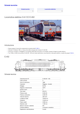
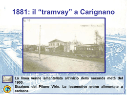
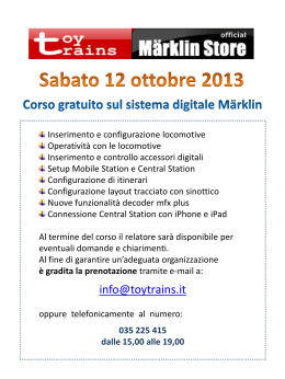
Elektronischer Fahrregler
51070
Inhaltsverzeichnis: Seite
Sicherheitshinweise4
Wichtige Hinweise
4
Technische Daten
4
Anschluss 4
Bedienung5
Bilder 16
Table of Contents: Page
Safety Notes
6
Important Notes
6
Technical Data
6
Connections6
Operations7
Figures16
2
Sommaire : Page
Remarques importantes sur la sécurité
8
Informations importante
8
Caractéristiques techniques 8
Raccordement8
Entretien et maintien
9
Images16
Índice: Página
Advertencias de seguridad 12
Notas importantes
12
Datos técnicos
12
Conexión 12
Manejo13
Imágenes 16
Inhoudsopgave:Pagina
Veiligheidsvoorschriften10
Belangrijke aanwijzingen
10
Technische gegevens
10
Aansluitingen10
Bediening11
Afbeeldingen16
Elenco del contenuto: Pagina
Avvertenze di sicurezza
14
Avvertenze importanti
14
Dati tecnici
14
Collegamento 14
Azionamento15
Figure 16
3
Sicherheitshinweise
Lesen Sie unbedingt die folgenden Sicherheitshinweise vor
dem ersten Einsatz eines Fahrreglers:
• Das Fahrpult ist ausschließlich zum Gebrauch in trockenen Räumen bestimmt.
• Das Fahrpult ist kein Spielzeug. Es dient zum Betrieb der
Modellbahnanlage.
Wichtige Hinweise
• Die Bedienungsanleitung ist Bestandteil des Produktes
und muss deshalb aufbewahrt sowie bei Weitergabe des
Produktes mitgegeben werden.
• Falscher Anschluss des Fahrpults führt zur Beschädigung
des Geräts.
• Entsorgung: www.maerklin.com/en/imprint.html
Vorsicht! Verwenden Sie zum Anschluß des Fahrreglers
Kabel mit einem Querschnitt von mindestens 0,5 mm2
(z. B. LGB 50160).
Technische Daten
Eingangsspannung:
14 – 20 V Wechselspannung oder
max. 16 – 24 V Gleichspannung
Ausgangsspannung: 0 – 22 V Gleichspannung
Ausgangsstrom: max. 5 A Gleichstrom
4
Anschluss (Bild 1, 2 & 3)
• Anschlüsse 1 und 2 hinten am Fahrregler mit den Gleisen
verbinden (Bild 2 & 3).
• Anschlüsse 3 und 4 mit einem LGB-Trafo verbinden.
• Sie können den Elektronischen Fahrregler 51070 mit
jedem LGB-Trafo/Schaltnetzteil betreiben. Optimal geeignet ist der Trafo/Schaltnetzteil 51095. Der zur Verfügung
stehende Fahrstrom hängt vom Trafo/Schaltnetzteil
ab, bis zu einem Maximum von 5 Ampere. Sie können
auch einen Trafo/Schaltnetzteil mit mehr als 5 Ampere
verwenden, doch ist hier der maximale Fahrstrom auf 5
Ampere begrenzt. Das verwendete Gleisanschlusskabel
darf maximal 2 Meter lang sein.
Funkfernsteuerung
Am Fahrregler 51070 kann der RC-Empfänger 55055 angeschlossen werden (Bild 2 & 3). So kann die Fahrgeschwindigkeit und die Fahrtrichtung mit dem Lok-Handy 55016 (mit
RC-Sender 55050) drahtlos gesteuert werden.
(Sie können auch das Universal-Handy 55015 einsetzen.)
Der Funkhandregler ist nur aktiv, so lange der Regler am
Fahrpult 51070 auf 0 steht (Mittelstellung).
BEDIENUNG
Die grüne Betriebsanzeige (Bild 1) zeigt an, dass der Fahrregler betriebsbereit ist.
• Regelknopf nach rechts oder links drehen, um die Lok
vorwärts fahren zu lassen.
• Regelknopf in die andere Richtung drehen, um die Lok
rückwärts fahren zu lassen.
Stop/Halt-Taste
Drücken Sie auf die Stop/Halt-Taste, um alle fahrenden Lokomotiven schnell anzuhalten. Das Gleis ist dann spannungsfrei.
Nach einem erneuten Druck auf die Stop/Halt-Taste fahren
alle Lokomotiven wie zuvor weiter.
Booster-Taste
Durch einen Druck auf die Booster-Taste wird die volle
vorhandene Leistung an das Gleis gesendet. So können Sie
z.B. einer Lokomotive mit einem schweren Zug am Berg
„helfen“, ohne den Regler verstellen zu müssen.
Fahrspannungsnachführung (bei Laständerung)
Der Fahrregler 51070 ist mit einer fest eingestellten
Fahrspannungsnachführung ausgestattet. Bei steigendem
Fahrstrom sinkt die Motorspannung der Fahrzeuge durch
Verluste auf dem Weg vom Fahrregler zur Lokomotive. Dies
wird durch eine proportional zum Fahrstrom des Fahrreglers
steigende Ausgangsspannung automatisch kompensiert.
Hinweis: Die Fahrspannungsnachführung funktioniert nur
bei nicht voll aufgedrehtem Fahrregler und einer TrafoAusgangsspannung von 18 V Wechselspannung oder 24 V
Gleichspannung, da eine Spannungsreserve erforderlich ist.
Betriebsanzeige (Bild 1)
grün Bereitschaft des Fahrpults
rot Übertemperatur
rot blinkend Kurzschluss, Überlast oder Abschaltung mit
der Stop/Halt-Taste.
Überlast-Sicherung
Der Fahrregler ist mit einer Kurzschluss-Sicherung ausgestattet. Bei Überlast am Gleis oder Kurzschluss schaltet sich
das Fahrpult ab.
Wenn Ihr LGB-Trafo/Schaltnetzteil weniger als 5 A abgibt,
wird bei einem Kurzschluss die Überlast-Sicherung des
Trafos/Schaltnetzteils ausgelöst.
1. Kurzschluss: Beheben Sie die Ursache des Kurzschlusses. Drücken Sie die Stop-Taste, um den Fahrregler
wieder einzuschalten.
2. Überlastung: Nehmen Sie eine oder mehrere Loks vom
Gleis. Drücken Sie die Stop-Taste, um den Fahrregler
wieder einzuschalten.
5
Safety Notes
Make sure you read the following safety notes before using
this controller for the first time:
• This locomotive controller is designed for use only in dry
areas.
• This locomotive controller is not a toy. It is used to operate a model railroad layout.
Important Notes
• These instructions are an integral part of the product
and must therefore be kept with the product even if you
transfer the product to someone else.
• Incorrect hookup of this locomotive controller will damage it.
• Disposing: www.maerklin.com/en/imprint.html
Caution! Use wire with a cross section of at least 0.5 square
millimeters or 20 gauge wire to hook this locomotive controller to a layout (example: LGB 50160).
Technical Data
Input voltage:
14 – 20 volts AC or
max. 16 – 24 volts DC
Output voltage: 0 – 22 volts DC
Output current: max. 5 amps DC
6
Connections (Fig.1, 2 & 3)
• Connect terminals 1 and 2 on the back of the locomotive
controller to the track (Fig. 2 & 3).
• Connect terminals 3 and 4 to an LGB transformer.
• You can operate the 51070 electronic locomotive
controller with any LGB transformer / switched mode
power pack. The 51095 transformer / switched mode
power pack is designed to be used with this controller.
The available track current depends on the transformer /
switched mode power pack, up to a maximum of 5 amps.
You can use a transformer / switched mode power pack
with more than 5 amps, but the maximum track current
with this controller is limited to 5 amps. The wire used to
connect the controller to the track can be a maximum of 2
meters / 78 inches long.
Radio Remote Control
The 55055 radio control receiver can be connected to the
51070 locomotive controller (Fig. 2 & 3). A locomotive‘s
speed and direction can be controlled without wires with
the 55016 walk-around controller (with the 55050 radio
control sender). (You can also use the 55015 universal walkaround controller).
The radio hand controller is only active as long as the
control knob on the 51070 locomotive controller is set at 0
(center position).
OPERATION
The green pilot light (Fig. 1) indicates that the locomotive
controller is ready to be used.
• Turn the control knob to the right or left in order to make
the locomotive go forward.
• Turn the control knob in the other direction to make the
locomotive go in reverse.
Stop/Halt Button
Press on the Stop/Halt button in order to stop all running
locomotive quickly. The track at this point has no voltage
present in it. All of the locomotive will run as they were
previously doing after you press a second time on the Stop/
Halt button.
Booster Button
Pressing on the Booster button will send the full available
power to the track. This allows you to “help“ a locomotive
with a heavy train on a mountain without have to adjust the
control knob.
Track Voltage Compensation (with a change in load)
The 51070 locomotive controller is equipped with a permanently set track voltage compensation feature. When the
track current increases, the motor voltage in the locomotives decreases due to voltage drop on the way from the
locomotive controller to the locomotive. This is automatically
compensated by an increase in the output voltage proportional to the track current from the locomotive controller.
Note: The track voltage compensation feature only works
when the control knob is not turned up full and with a transformer output voltage of 18 volts AC or 24 volts DC, since a
voltage reserve is necessary.
Pilot Light (Fig. 1)
green locomotive controller is ready to use
red operating temperature is too high
blinking red short circuit, overload, or power shutoff with
the Stop/Halt button.
Overload Protection
This locomotive controller is equipped with short circuit
protection. In the event of an overload on the track or a
short circuit, the locomotive controller shuts off.
If your LGB transformer / switched mode power pack
provides less than 5 amps, the overload protection in the
transformer / switched mode power pack will be activated
in the event of a short circuit.
1. Short circuit: Correct the cause of the short circuit. Press
the Stop button in order to turn the locomotive controller
back on.
2. Overload: Take one or several locomotives off of the
track. Press the Stop button in order to turn the locomotive controller back on.
7
Remarques importantes sur la sécurité
Avant la première utilisation du régulateur de marche, lire
impérativement les indications de sécurité suivantes:
• Le régulateur de marche est conçu pour être utilisé
exclusivement dans des endroits secs.
• Le pupitre de commande n’est pas un jouet. Il sert à
l’exploitation du réseau miniature.
Information Importantes
• La notice d’utilisation fait partie intégrante du produit et
doit donc être conservée, voire, le cas échéant, transmise avec le produit.
• Un raccordement incorrect du pupitre de commande
risque d’endommager l’appareil.
• Elimination : www.maerklin.com/en/imprint.html
Attention! Pour le raccordement du régulateur de marche,
utiliser uniquement des fils d’une section minimale de 0,5
mm2 (par ex. LGB 50160).
Caractéristiques techniques
Tension d’entrée:
14 – 20 V tension alternative ou
max. 16 – 24 V tension continue
Tension de sortie : 0 – 22 V tension continue
Courant de sortie : max. 5 A courant continu
8
Raccordement (Img. 1, 2 & 3)
• Raccorder à la voie les connexions 1 et 2 situées derrière
le régulateur (Img. 2 & 3).
• Raccorder les connexions 3 et 4 à un transformateur LGB.
• Le régulateur de marche électronique réf. 51070 peut
être exploité avec n’importe quel transformateur/convertisseur LGB. Dans l’idéal, utiliser le transformateur
réf.51095. Le courant traction disponible dépend du
transformateur/convertisseur et peut atteindre un maximum de 5 ampères. Vous pouvez également utiliser un
transformateur/convertisseur de plus de 5 ampères, mais
le courant traction maximal est limité à 5 ampères. La
longueur maximale du câble de raccordement à la voie
doit être de 2 mètres.
Radiotélécommande
Le récepteur RC 55055 peut être branché sur le régulateur
de marche réf. 51070 (Img. 2 & 3). Le loco-handy 55016 (avec
émetteur RC 55050) permet alors de commander vitesse et
sens de marche sans fil. (Vous pouvez également utiliser le
Universal-Handy 55015).
Le régulateur sans fil est activé uniquement quand le régulateur du pupitre 51070 est réglé sur 0 (position centrale).
UTILISATION
Le voyant vert (Img. 1) indique que le régulateur de marche
est prêt à fonctionner.
• Tourner le bouton de réglage vers la droite ou vers la
gauche pour une marche avant de la locomotive.
• Tourner le bouton dans l’autre sens pour une marche
arrière de la locomotive.
Touche Stop
Appuyer sur la touche Stop pour arrêter rapidement toutes
les locomotives en marche. La voie est alors hors tension.
Pour faire repartir les locomotives, appuyer à nouveau sur
la touche Stop.
Touche Booster
La touche Booster permet d’envoyer toute la puissance
disponible dans la voie. Ainsi, vous pouvez par exemple
“aider“ une locomotive remorquant un train lourd à franchir
une rampe sans avoir à toucher au régulateur.
Appariement en tension
(en cas de modification de la charge)
Le régulateur de marche 51070 est équipé d’un système
d’appariement en tension. Si le courant traction augmente,
la tension moteur des véhicules chute en raison des pertes
entre le régulateur et la locomotive. Ceci est automatiquement compensé par une augmentation de la tension de
sortie proportionnelle au courant traction du régulateur.
Indication: L’appariement en tension fonctionne uniquement
si le régulateur n’est pas poussé à fond et si la tension de
sortie du transformateur est de 18 V (tension alternative)
ou de 24 V (tension continue), une tension de réserve étant
nécessaire.
Voyant d’état (Img 1)
Vert Pupitre prêt à fonctionner
Rouge Surtempérature
Rouge clignotant
Court-circuit, surcharge ou mise
hors circuit avec la touche Stop.
Protection contre les surcharges
Le régulateur de marche est équipé d’une protection contre
les courts-circuits. En cas de surcharge ou de court-circuit
sur la voie, le pupitre de commande s’éteint automatiquement.
Si votre transformateur/convertisseur LGB fournit moins de
5 A, la protection contre les surcharges du transformateur/
convertisseur se déclenche en cas de court-circuit.
1. Court-circuit : Eliminez la cause du court-circuit. Appuyez
sur la touche Stop pour remettre le régulateur sous
tension.
2. Surcharge : Retirez une ou plusieurs locomotive(s) de la
voie. Appuyez sur la touche Stop pour remettre le régulateur sous tension.
9
Veiligheidsvoorschriften
Lees, voordat u het apparaat gaat gebruiken, de volgende
veiligheidsvoorschriften aandachtig door:
• De rijregelaar is uitsluitend bestemd voor het gebruik in
droge ruimtes.
• De rijregelaar is geen speelgoed. Het dient voor het
besturen van een modelbaan.
Belangrijke aanwijzingen
• De gebruiksaanwijzing en de verpakking zijn bestandsdelen van het product en dienen daarom bewaard te
worden en met het afgeven van het product meegegeven
te worden.
• Het foutief aansluiten van de rijregelaar leidt tot beschadiging van het apparaat.
• Afdanken: www.maerklin.com/en/imprint.html
Voorzichtig! Gebruik voor het aansluiten van de rijregelaar
een draad met een doorsnede van minimaal 0,5 mm² ( bijv.
LGB 50160).
Technische gegevens
Ingangsspanning:
14-20 V wisselspanning of max.
16 – 24 V gelijkspanning.
Uitgangsspanning: 0 – 22 V gelijkspanning
Uitgangsstroom: max. 5 A gelijkstroom
10
Aansluitingen (afb. 1, 2 & 3)
• Aansluitingen 1 en 2 achter aan de rijregelaar met de
rails verbinden ( afb. 2 & 3).
• Aansluitingen 3 en 4 met een LGB-trafo verbinden.
• U kunt de elektronische rijregelaar 51070 met elke LGBtrafo/netadapter gebruiken. Optimaal geschikt hiervoor
is de netadapter 51095. De beschikbare rijstroom is
afhankelijk van de trafo/netadapter, tot een maximum van
5 Ampère. U kunt ook een trafo/netadapter gebruiken
die meer dan 5 Ampère kan leveren, maar ook dan is de
maximale rijstroom begrensd op 5 Ampère. De gebruikte
aansluitkabel naar de rails mag maximaal 2 meter lang
zijn.
Radiografische afstandbesturing
Op de rijregelaar 51070 kan de RC-ontvanger 55055 aangesloten worden (afb. 2 & 3). Zo kan de rijsnelheid en de
rijrichting met de Loc-handy 55016 ( met RC-zender 55050)
draadloos bestuurd worden.
( u kunt ook de universele-handy 55015 gebruiken).
De radiografische regelaar is alleen actief zolang de regelknop op de rijregelaar op “0” staat ( middenstand).
Bediening
De groene bedrijfsled ( afb. 1) geeft weer dat de rijregelaar
klaar is voor het bedrijf.
• Regelknop naar rechts of links draaien om de loc vooruit
te laten rijden.
• Regelknop in de tegengestelde richting draaien op de loc
achteruit te laten rijden.
Stop/halt-toets
Druk op de stop/halt-toets om alle rijdende locomotieven
snel te laten stoppen. Er staat dan geen stroom meer op de
rails. Nadat opnieuw op de stop/halt-toets wordt gedrukt
rijden alle locomotieven weer als voorheen.
Booster-toets
Door op de booster-toets te drukken wordt het hele beschikbare vermogen naar de rails gestuurd. Zo kunt u bijv. een
locomotief met een zware trein de berg op “helpen”, zonder
de rijregelaar te moeten verstellen.
Rijspanning naregeling ( bij veranderende belasting)
De rijregelaar 51070 is voorzien van een vast ingestelde
rijspanning naregeling. Bij een stijgende rijstroom zakt de
motorspanning van de voertuigen door verliezen onderweg
tussen de rijregelaar en de locomotief. Dit wordt gecompenseerd door automatisch de rijspanning proportioneel t.o.v.
de rijstroom te verhogen.
Opmerking: De rijspanning naregeling werkt alleen bij een
niet voluit gedraaide regelaar en een trafo uitgangsspanning van 18V wissel- of 24V gelijkspanning aangezien een
spanningsreserve noodzakelijk is.
Bedrijfsled (afb. 1)
Groen
rijregelaar klaar voor gebruik
Rood
temperatuur te hoog
Rood knipperend
kortsluiting, overbelast of uitgeschakeld met de stop/halt-toets.
Overbelastingsbeveiliging
De rijregelaar is voorzien van een overbelastingsbeveiliging.
Bij een overbelasting op de rails of een kortsluiting schakelt
de rijregelaar zich uit. Als uw LGB-trafo/netadapter minder
dan 5 A levert, wordt bij een kortsluiting de overlastbeveiliging van de trafo/netadapter aangesproken.
1. kortsluiting: de oorzaak van de kortsluiting opheffen.
Druk op de stop/halt-toets om de rijregelaar weer in te
schakelen.
2. Overbelasting: neem één of meerdere locs van de rails.
Druk op de stop/halt-toets om de rijregelaar weer in te
schakelen.
11
Advertencias de seguridad
Antes del primer uso de un regulador de marcha es imprescindible leer las siguientes advertencias de seguridad.
• El pupitre de conducción se ha concebido para su uso
exclusivamente en recintos secos.
• El pupitre de conducción no es un juguete. Sirve para la
explotación de la maqueta de trenes.
Notas importantes
• Las instrucciones de empleo forman parte integrante
del producto y, por este motivo, deben conservarse y
entregarse al nuevo comprador en el caso de venta del
producto.
• Una conexión incorrecta del pupitre de conducción
provoca daños al aparato.
• Eliminación: www.maerklin.com/en/imprint.html
¡Precaución! Para conectar el regulador de marcha utilice
cables con una sección de como mínimo 0,5 mm2
(p. ej., LGB 50160).
Datos técnicos
Tensión de entrada:
14 – 20 V c.a. o
máx. 16 – 24 V c.c.
Tensión de salida: 0 – 22 V c.c.
Intensidad de salida: máx. 5 A c.c.
12
Conexión (imágenes 1, 2 y 3)
• Conectar los bornes 1 y 2 situados en la parte posterior
del regulador de marcha (imágenes 2 y 3).
• Conectar los bornes 3 y 4 a un transformador LGB.
• Puede utilizar el regulador de marcha electrónico 51070
con cualquier transformador/fuente de alimentación conmutada 51070. El aparato óptimo es el transformador/la
fuente de alimentación conmutada 51095. La corriente de
tracción disponible depende del transformador/la fuente
de alimentación hasta un máximo de 5 amperios. Puede
utilizar también un transformador/fuente de alimentación
de más de 5 amperios; sin embargo, en éstos la corriente
de tracción máxima está limitada a 5 amperios. El cable
de conexión de vías empleado puede tener una longitud
máxima de 2 metros.
Radiotelemando
Se puede conectar al regulador de marcha 51070 el receptor de control remoto 55055 (imágenes 2 y 3). De este modo,
es posible el control remoto inalámbrico de la velocidad y
el sentido de circulación con el móvil de loco 55016 (con
emisor de control remoto 55050).
(Puede utilizar también el móvil universal 55015.)
El radiotelemando está activo únicamente mientras el regulador del pupitre de conducción 51070 esté en la posición 0
(posición central).
MANEJO
El indicador operacional verde (imagen 1) muestra que el
regulador de marcha está operativo.
• Girar el pomo regulador hacia la derecha o hacia la
izquierda para que la locomotora circule hacia delante.
• Girar el pomo regulador en el otro sentido para que la
locomotora circule hacia atrás.
Botón Stop/Parada
Pulse el botón Stop/Parada para detener rápidamente todas
las locomotoras en circulación. Al hacerlo, la vía queda sin
tensión. Después de pulsar de nuevo el botón Stop/Parada,
todas las locomotoras continúan circulando como antes.
Tecla Booster
Pulsando la tecla Booster se envía a la vía toda la potencia
disponible. De este modo puede „ayudar“ a ascender por el
trayecto en rampa, p. ej., con un tren pesado sin tener que
variar el ajuste del regulador.
Control de compensación de la tensión de tracción
(en el caso de variación de la carga)
El regulador de marcha 51070 está equipado con un control
de compensación de la tensión de tracción ajustada fija. Si
aumenta la corriente de tracción, disminuye la tensión del
motor de los vehículos como consecuencia de las pérdidas
en el recorrido desde el regulador de marcha hacia la
locomotora. Esto se compensa automáticamente mediante
una tensión de salida que aumenta proporcionalmente a la
corriente de tracción del regulador de marcha.
Nota: El control de compensación de la tensión de tracción
funciona sólo si el regulador de marcha no está totalmente
abierto y la tensión de salida del transformador es 18 V c.a.
o 24 V c.c., ya que se requiere una reserva de tensión.
Indicador funcional (imagen 1)
verde Pupitre de conducción operativo
rojo Sobretemperatura
rojo intermitente Cortocircuito, sobrecarga o desconexión con la tecla Stop/Parada.
Protección eléctrica contra sobrecarga
El regulador de marcha está equipado con una protección
eléctrica contra cortocircuito. En el caso de sobrecarga en
la vía o de cortocircuito, se apaga el pupitre de conducción.
Si el transformador/la fuente de alimentación conmutada
LGB entrega menos de 5 A, en caso de cortocircuito se
activa la protección eléctrica contra sobrecarga del transformador/la fuente de alimentación conmutada LGB.
1. Cortocircuito: Subsane la causa del cortocircuito. Pulse
la tecla Stop para encender de nuevo el regulador de
marcha.
2. Sobrecarga: Retire una o varias locomotoras de la vía.
Pulse la tecla Stop para encender de nuevo el regulador
de marcha.
13
Avvertenze di sicurezza
Vogliate leggere assolutamente le seguenti avvertenze di sicurezza prima del primo impiego di un regolatore di marcia:
• Tale quadro di comando della marcia è progettato esclusivamente per l‘utilizzo in ambienti asciutti.
• Tale quadro di comando della marcia non è affatto un
giocattolo. Esso serve al funzionamento dell‘impianto di
ferrovia in miniatura.
Avvertenze importanti
• Le istruzioni di impiego sono parte costitutiva del prodotto
e devono pertanto venire preservate nonché consegnate
in dotazione in caso di cessione del prodotto.
• Un errato collegamento del quadro di comando della
marcia conduce al danneggiamento di tale apparato.
• Smaltimento: www.maerklin.com/en/imprint.html
Attenzione! Per il collegamento del regolatore di marcia
vogliate utilizzare dei cavetti con una sezione trasversale
come minimo di 0,5 mm2 (ad es. LGB 50160).
Dati tecnici
Tensione di ingresso:
14 – 20 V a tensione alternata oppure
al max. 16 – 24 V a tensione continua
Tensione di uscita: 0 – 22 V a tensione continua
Corrente di uscita: max. 5 A in corrente continua
14
Collegamenti (figure 1, 2 & 3)
• Collegare le connessioni 1 e 2 dietro al regolatore di
marcia con il binario (figure 2 & 3).
• Collegare le connessioni 3 e 4 con un trasformatore LGB.
• Voi potete mettere in funzione il regolatore di marcia
elettronico 51070 con ciascun trasformatore/alimentatore
“switching” da rete LGB. Adatto in modo ottimale è il
trasformatore/alimentatore “switching” da rete 51095. La
corrente di trazione che si trova a disposizione dipende
dal trasformatore/alimentatore “switching” da rete, sino
ad un massimo di 5 ampere. Voi potete anche utilizzare un
trasformatore/alimentatore “switching” da rete con più di
5 ampere, tuttavia qui la corrente di trazione massima è
limitata a 5 ampere. Il cavetto di collegamento al binario
utilizzato deve essere lungo al massimo 2 metri.
Comando a distanza via radio
Al regolatore di marcia 51070 può venire collegato il ricevitore RC 55055 (figure 2 & 3). Così la velocità di marcia e la
direzione di marcia possono venire comandate senza fili con
il comando manuale da locomotive 55016 (con trasmettitore
RC 55050).
(Voi potete impiegare anche il comando manuale universale
55015.)
Tale regolatore manuale via radio è attivo solamente fino
a quando il regolatore sul quadro di comando della marcia
51070 si trova sullo 0 (posizione intermedia).
AZIONAMENTO
L’indicatore di funzionamento verde (figura 1) indica che il
regolatore di marcia è pronto all’esercizio.
• Ruotare la manopola di regolazione verso destra oppure
verso sinistra, per fare marciare la locomotiva in avanti.
• Ruotare la manopola di regolazione nell’altra direzione,
per fare marciare la locomotiva all’indietro.
Tasto Stop/Fermata
Premete sul tasto Stop/Fermata, per far arrestare rapidamente tutte le locomotive in marcia. Il binario è allora esente
da tensione. Dopo una rinnovata pressione sul tasto Stop/
Fermata, tutte le locomotive marciano nuovamente come
prima.
Tasto Booster
Mediante una pressione sul tasto Booster viene inviata
sul binario la totale potenza disponibile. Così Voi potete ad
esempio „aiutare“ una data locomotiva con un treno pesante in montagna, senza dovere ritoccare il regolatore.
Inseguimento della tensione di trazione
(in caso di variazione di carico)
Il regolatore di marcia 51070 è equipaggiato con un
inseguimento della tensione di trazione impostato in modo
fisso. In caso di corrente di trazione crescente, la tensione
del motore dei rotabili si abbassa a causa delle perdite sul
percorso dal regolatore di marcia alla locomotiva. Questo
viene automaticamente compensato tramite una tensione
di uscita crescente in modo proporzionale alla corrente di
trazione del regolatore di marcia.
Avvertenza: L’inseguimento della tensione di trazione funziona soltanto con regolatore di marcia non completamente
ruotato ed una tensione di uscita del trasformatore di 18 V
con tensione alternata oppure 24 V con tensione continua,
poiché è necessaria una riserva di tensione.
Indicazioni del funzionamento (figura 1)
verde stato di quadro di comando della marcia
pronto
rosso sovra-temperatura
rosso lampeggiante corto circuito, sovraccarico oppure
disattivazione con il tasto Stop/Fermata.
Protezione dal sovraccarico
Tale regolatore di marcia è equipaggiato con una protezione
dal corto circuito. In caso di sovraccarico sul binario oppure
corto circuito, il quadro di comando della marcia si disattiva.
Qualora il Vostro trasformatore/alimentatore “switching” da
rete LGB eroghi meno di 5 A, in presenza di un corto circuito
viene fatta scattare la protezione da sovraccarico del
trasformatore/alimentatore “switching” da rete.
1. Corto circuito: rimuovete l’origine del corto circuito. Premete il tasto Stop, per attivare nuovamente il regolatore
di marcia.
2. Sovraccarico: vogliate togliere una oppure alcune
locomotive dal binario. Premete il tasto Stop, per attivare
nuovamente il regolatore di marcia.
15
4
3
Img. 1
2
1
5
Bild 1 Fig. 1 16
Bedienelemente
1 Stop/Halt-Taste
2 Anzeige Fahrtrichtung 1
3 Betriebsanzeige
4 Anzeige Fahrtichtung 2
5 Booster-Taste
Operation Elements
1 Stop/Halt button
2 Indicator for direction of travel 1
3 Pilot light
4 Indicator for direction of travel 2
5 Booster button
Eléments de commande
1 Touche Stop
2 Affichage sens de marche 1
3 Voyant d’état
4 Affichage sens de marche 2
5 Touche Booster
Afb. 1 Bedieningselementen
1Stop/halt-toets
2 Weergave rijrichting 1
3Bedrijfsled
4 Weergave rijrichting 2
5Booster-toets
Figura 1 Elementos de mando
1 Tecla Stop/Parada
2 Indicador de sentido de marcha 1
3 Indicador funcional
4 Indicador de sentido de marcha 2
5 Tecla Booster
Figura 1 Elementi di azionamento
1 Tasto Stop/Fermata
2 Indicazione senso di marcia 1
3 Indicazione di funzionamento
4 Indicazione senso di marcia 2
5 Tasto Booster
Img. 2
1
1
Bild 2 Fig. 2 2
2
3
5
3
Die Anschlüsse
1 Gleisanschluss, rot
2 Gleisanschluss, blau
3 Spannungsquelle / Trafo
4 Spannungsquelle / Trafo
5 RC-Empfänger
Connections
1 Track connection, red
2 Track connection, blue
3 Voltage source / Transformer
4 Voltage source / Transformer
5 Wireless Receiver
4
4
Les connexions
1 Connexion à la voie, rouge
2 Connexion à la voie, bleu
3 Source de tension / transformateur
4 Source de tension / transformateur
5 Récepteur sans fil
Afb. 2 De aansluitingen
1 Railaansluiting, rood
2 Railaansluiting, blauw
3 Spanningsbron / trafo
4 Spanningsbron / trafo
5RC-ontvanger
Figura 2 Los bornes
1 Conexión de vía, rojo
2 Conexión de vía, azul
3 Fuente de tensión/transformador
4 Fuente de tensión/transformador
5 Receptor Control Remoto
Figura 2 Le connessioni
1 Connessione al binario, rosso
2 Connessione al binario, blu
3 Fonte di tensione / Trasformatore
4 Fonte di tensione / Trasformatore
5 Ricevitore RC
17
18
55055
55050
Märklin
60200
55050
Bild 3 Anschlussbild
Fig. 3 Wiring diagram
Img. 3 Schéma des connexions
Afb. 3 Aansluitschema
Figura 3 Esquema de conexión
Figura 3 Schema di connessione
51070
51095
19
This device complies with Part 15 of the FCC Rules.
Operation is subject to the following two conditions:
(1) This device may not cause harmful interference, and
(2) this device must accept any interference received, including
interference that may cause undesired operation.
Gebr. Märklin & Cie. GmbH
Stuttgarter Straße 55 - 57
73033 Göppingen
Germany
www.lgb.de
www.maerklin.com/en/imprint.html
130128/0414/Sm4Ef
Änderungen vorbehalten
© Gebr. Märklin & Cie. GmbH
Scarica