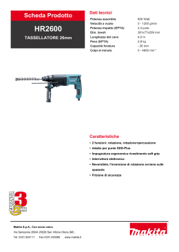
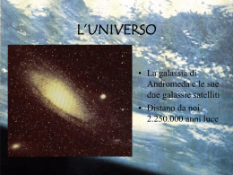
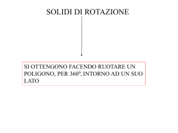
Cilindri rotanti serie ERC
.i
t
• Disponibili con albero maschio e con albero cavo
• Semplice regolazione della posizione iniziale
• Angolo di lavoro regolabile
• ø25 ~ ø100mm
• Corse 90°, 180°, 270°, 360°, su richiesta
ww
d
k
c
w.
INFORMAZIONI TECNICHE - TECHNICAL INFORMATION
Fluido - Fluid:
aria filtrata 40 µm lubrificata o non lubrificata (se lubrificata usare olio per circuiti pneumatici).
filtered air 40 µm lubricated or not lubricated ( when lubricated use oil for pneumatic circuits).
Temperatura fluido ed ambiente - Fluid and room temperature:
-10/+80 °C (consultare la tabella varianti dei cilindri e temperature di utilizzo dei finecorsa).
(see the table of cylinder variants and the temperatures for the utilization of limit switches).
Pressione di esercizio - Working pressure: 2 ÷ 10 bar
Tab. 1
Angolo di ammortizzo - Cushioning angle
Alesaggio - Bore (mm)
25
32
40
50
63
80
100
Angolo - Angle (°)
45
45
45
35
35
35
35
Rotazione dell’asse espressa in gradi nel quale agisce effettivamente l’ammortizzo.
Shaft rotation expressed in degrees during which the pneumatic cushioning really works.
Tab. 2
Massima energia cinetica ammortizzabile - Max cushioning kinetic energy
Alesaggio - Bore (mm)
25
32
40
50
63
80
100
Energia - Energy ( J )
1,2
1,9
2,2
4
6
11
16
Si tenga presente che la regolazione dell’ angolo di rotazione riduce l’effetto ammortizzante.
Please remark that the regulation of the angle of rotation reduces the cushioning effect.
Tab. 3
Angolo di regolazione - Angle of regulation
Alesaggio - Bore (mm)
Angolo - Angle (°)
25
32
40
50
63
80
100
+10 / -5
+10 / -7
+10 / -5
+10 / -7
+10 / -5
+10 / -7
+10 / -5
Si tenga presente che la regolazione dell’ angolo di rotazione riduce l’ effetto ammortizzante.
Effettuare la regolazione dell’ angolo di rotazione con il cilindro non in pressione.
Please remark that the regulation of the angle of rotation reduces the cushioning effect.
The regulation of the angle of rotation must be made without pressure in the cylinder.
Tab. 4
Momento torcente teorico - Theoretical torquing moment
Alesaggio - Bore (mm)
Momento - Momento (N•m/bar)
25
32
40
50
63
80
100
0,6
1,2
2,3
4,2
7,5
17,5
34,5
Coppia all’asse di rotazione alla pressione di 1 bar. Es.: Per ottenere il valore del momento torcente alla
pressione di 5 bar del cilindro prescelto, moltiplicare il valore in tabella per 5.
Torque on the axis of rotation at the pressure of 1 bar. Ex.: In order to obtain the value of the torquing moment at
the pressure of 5 bar of the chosen cylinder, multiply the value by 5.
Consumo d’aria - Air consumption
La determinazione del consumo di aria libera del cilindro rotante espresso
in Nl / min risulta di notevole importanza per la scelta del compressore e può
essere fatto utilizzando la seguente formula:
It is very important to determine the free air consumption, expressed in NI / min,
inside the rotating cylinder for the choice of compressor and this can be
evaluated by using the following formula:
Q = Kr•n•(p+1)
Q
Kr
n
p
=
=
=
=
Consumo di aria (Nl/min) - Air consumption
Volume per ciclo (dm3) - Volume for cycle
N° di cicli al minuto (x/min) - N° of cycles for minute
pressione relativa di lavoro (bar) - Working pressure
CILINDRI ROTANTI ED ACCESSORI
ROTATING CYLINDERS AND ACCESSORIES
Tab. 5
Ø
(mm)
Kr (dm )
180°
270°
3
90°
360°
25
0,0383 0,0766
0,1149
0,1532
32
0,0756 0,1512
0,2267
0,3023
40
0,1432 0,2864
0,4295
0,5727
50
0,2591 0,5182
0,7773
1,0364
63
0,4674 0,9348
1,4022
1,8696
80
1,1053 2,2106
3,3158
4,4211
100
1,9625 3,9250
5,8875
7,8500
DIMENSIONI DI INGOMBRO - OVERALL DIMENSIONS
ØFA
FB
I
G
CH
Y
L
HH
N
J
M
FC
F
F
A
C
E
F
*
D
ØK
1
X1
ØK
T
V
versione albero maschio
male shaft version
S
Q
1
X1
R
P
X2
X2
U
B
versione pignone femmina
female pinion version
W
ØZ
per la versione provvista di regolazione della rotazione
*) Solo
Only for the version provided with the regulation of the rotation
90°
A
180° 270° 360°
90°
B*
180° 270° 360°
C
D
E
F
G
H
I
J
L
25
163
202
241 280
183
222
261
300
43
G1/8
34
5,2
35
50
32,9
17,1
11,2
32
208
255
302 350
238
285
332
379
54
G1/8
44
5,2
47
64
41,5
22,5
16
40
238
295
352 408
269
326
383
439
60
G1/4
46
6,5
53
70
47
23
17
50
261
327
393 459
297
363
429
495
75
G1/4
58
6,5
65
84
54,5
29,5
20,5
63
295
370
445 520
332
407
482
558
85
G3/8
69
8,5
75
100
65
35
22,5
80
360
470
580 690
413
523
633
743
110
G3/8
90
10,5
95
130
86
44
28
100
395
520
646 771
450
575
700
826
120
G1/2
96
10,5 115
148 100,5
47,5
38
M
N
P
Q
R
S
T
U
V
W
X1
X2
Y
Z h6
K
FA H7
FB
FC
CH
25
21,7
59
64
25
38
4
18
25,5
3
M4
-
-
18,5
10
12
8
3
9
4
32
27
73
81
33
47
5
20
32,5
5
M5
14
4,5
22,8
14
15
8
3
9,4
4
40
29,5
83
90
33
56
5
20
38
5
M5
15,5
5,5
26,8
15
17
10
3
11,4
4
50
38,5
102
109
40
68
5
30
46,5
6
M6
10,5
8,5
30,1
18
25
14
5
16,3
6
Alesaggio - Bore
Alesaggio - Bore
(mm)
(mm)
63
43
116
123
44
78
4
35
56,5
6
M6
13
8,5
34,1
20
30
20
6
22,8
6
80
53,5
149
147
48
98
5
40
72
8
M8
13
8,5
48
25
40
20
6
22,8
6
100
59,5 171,5 181
60
120
5
50
89
10
M10
15
10
53,5
35
55
25
8
28,3
6
Tolleranze nominali sulla rotazione - Nominal tollerances on the rotation : +1 / -0°
Gioco pignone - cremagliera - Pinion - rack clearance : < 0,5°
CILINDRI ROTANTI ED ACCESSORI
ROTATING CYLINDERS AND ACCESSORIES
CODICI DI ORDINAZIONE - CYLINDERS ORDER CODES
Codici delle varianti eventualmente richieste
Codes of variants possibly requested
Codice
Code
maschio
male shaft
M albero
femmina
female pinion
F pignone
Cilindro
rotante
Rotating
cylinder
alesaggio
bore (mm):
25; 32; 40; 50;
63; 80; 100.
Varianti - Variants
Magnetico
Magnetic
Regolazione della rotazione
Regulation of rotation
Tenute in elastometro fluorurato
M
R
angolo (gradi)
angle (degrees):
90°; 180°;
270°; 360°.
(versione non magnetica, max 150°)
V
Seals in fluorine rubber
(non magnetic version, max 150°)
Versione idraulica
(max 10 bar, non ammortizzata)
O
ERC M 0 4 0 0 9 0 V
Hydraulic version
(max 10 bar, not cushioned)
Non ammortizzato
Not cushioned
Rotaz. albero in senso antiorario
Counterclockwise shaft rotation
N
A
Angolo di rotazione a richiesta
...
(Indicare l’angolo di rotazione richiesto)
Upon request rotation angle
(The rotation angle must be indicated )
Come ordinare - Cylinders ordination code
Cilindro rotante con albero maschio, alesaggio 40 mm, rotazione di 90°,magnetico con regolazione della rotazione.
Rotating cylinder with male shaft with bore of 40 mm rotating 90° and device for the regulation of rotation.
ERM040.090.MR
Codice di ordinazione del kit di guarnizioni - Seals kit ordination code
Codice kit guarnizioni = SG + CR + alesaggio (+ eventuali varianti: V o O ).
Seals kit code = SG + CR + bore (+ possible versions: V or O ).
SG.CR.040
Materiali e dotazioni standard - Materials and standard outfit
Testate: ..................
Corpo: ...................
Pignone: ...............
Cremagliera: ........
Guarnizioni: .........
Camicia: ...............
Tiranti: ..................
alluminio pressofuso anodizzato
fusione di alluminio verniciato
acciaio bonificato
acciaio bonificato
gomma nitrilica
alluminio anodizzato
acciaio inox
Covers: ....................
Frame: .....................
Pinion: .....................
Rack: .......................
Seals: ......................
Tube: .......................
Tie rods: ..................
anodized die-cast aluminium
die-cast aluminium
Tempered steel
Tempered steel
nitrilic rubber
anodized aluminium
stainless steel
Direzione di rotazione - Rotating direction
Il cilindro viene fornito con la linguetta del pignone in posizione centrale
(vedi fig. 1) e la rotazione avviene in senso orario.
A richiesta può essere fornito con senso di rotazione antiorario.
360° 0°
270°
the cylinder can be supplied with the pinion tongue in central position (see fig. 1),
and the rotation is clockwise.
Upon request it can be supplied with a different rotating direction.
90°
180°
fig. 1
CILINDRI ROTANTI ED ACCESSORI
ROTATING CYLINDERS AND ACCESSORIES
REGOLAZIONE DELLA ROTAZIONE - REGULATION OF THE ROTATION
Il dispositivo di regolazione della rotazione è dotato di una guarnizione (1) che scorre su
superficie levigata, assicurando la tenuta anche dopo numerosi interventi di regolazione.
The device for the regulation is supplied with a seal (1) sliding on a smooth surface,
which assures pneumatic sealing even after several regulations.
1
1
fig. 3
fig. 2
SCELTA DEL CILINDRO ROTANTE - CHOICE OF THE ROTATING CYLINDER
Nella scelta del cilindro rotante si consiglia di considerare le seguenti indicazioni:
1) Dimensionare il cilindro con la coppia teorica (alla pressione di lavoro prescelta) pari ad 1,5 ÷ 2 volte il valore della coppia di carico.
2) Verificare la capacità di ammortizzo confrontando i valori presenti in tabella 2 con l’energia generata dal carico in oggetto.
L’energia del carico dipende dalla velocità di rotazione, dalla massa e dalla sua distribuzione rispetto all’asse di rotazione,
secondo la formula: Ec = 1/2 I 2.
3) I carichi radiali ed assiali non devono superare i valori indicati (tab. 5 e 6).
il nostro ufficio tecnico é a Vostra disposizione per eventuali chiarimenti in merito.
When choosing a rotating cylinder it is recommended to consider the following instructions:
1) Calibrate the cylinder with the theoretical torque (with the chosen working pressure) equivalent to 1,5 ÷ 2 times the value
of the loading torque.
2) Check the cushioning capability by comparing the values shown on table 2 to the energy produced by the load in
reference. The energy of the load depends on the rotation speed, on the mass, and on its distribution with regard to
the axis of rotation, according to the formula: Ec = 1/2 I 2.
3) Radial and axial loads must not exceed the values indicated (tables 5 and 6).
Our technical department is at your disposal for any further explanations.
Tab. 5
Carico assiale max (Fa: fig. 4, con Fr=0 ) - Maximum axial load ( Fa:fig. 4 with Fr=0)
Alesaggio - Bore (mm)
25
32
40
50
63
80
100
Carico - Load (N)
50
80
90
100
120
150
200
Carico massimo assiale consentito sull’albero rotante. Maximum axial load permitted on the axis of the rotating shaft.
Carico radiale massimo consentito in relazione
alla sporgenza sull’asse dell’albero rotante.
Maximum radial load permitted in relation to
projection on the axis of the rotating shaft.
S
Fa
assiale
axial
fig. 4
Fr
radiale
radial
Carico Radiale Fr - Radial load Fr ( N )
Carico radiale max (Fr: fig. 4, con Fa=0 ) - Maximum radial load ( Fr:fig. 4 with Fa=0)
Tab. 6
600
550
500
100
450
400
80
350
300
63
250
50
40
32
200
150
100
25
50
20
40
60
80
100 120 140 160 180 200
Sporgenza del carico S - Projection of load S ( mm )
CILINDRI ROTANTI ED ACCESSORI
ROTATING CYLINDERS AND ACCESSORIES
SENSORI MAGNETICI - MAGNETIC SWITCHES
Il sensore magnetico è un dispositivo elettronico che rileva la presenza di un campo magnetico. Collegato al cilindro
magnetico, viene prevalentemente utilizzato come interruttore di prossimità per aprire o chiudere un circuito elettrico.
La gamma di sensori proposti per gli attuatori ERC si articola su tre circuiti elettrici e due tipi di
connessione del cavo al corpo del sensore.
La versione con uscita diretta del cavo è la più semplice ed economica, mentre la versione con connettore a scatto
permette di realizzare eventuali manutenzioni del sensore stesso evitando onerose operazioni di cablaggio; in entrambi i
casi il grado di protezione è molto elevato IP 67. Il sensore nella versione ampolla Reed può essere scelto con circuito a
due fili oppure a tre fili permettendo quest’ultimo di effettuare collegamenti in serie dei sensori stessi nei casi in cui siano
necessari più consensi; questo vantaggio è dovuto al fatto che il led è alimentato separatamente pertanto non vi sono
cadute di tensione.
La versione elettronica (sensore magneto-resistivo) essendo priva di contatti elettrici ha i seguenti vantaggi rispetto
all’ampolla Reed: una durata superiore dell’ordine di 109 cicli contro i 107 ; tempi di chiusura ed apertura del circuito
notevolmente più bassi (praticamente inapprezzabili); isteresi inferiore. Questi vantaggi consentono di realizzare cicli più
rapidi dato che le velocità del cilindro possono essere più elevate ed inoltre possono essere utilizzati dei cavi più lunghi
rispetto al Reed perché meno influenzati dall’effetto capacitivo degli stessi. Il fissaggio dei sensori magnetici al cilindro
avviene per mezzo di staffe in alluminio opportunamente sagomate e dotate di un pratico sistema di bloccaggio che le
rende insensibili alle vibrazioni e rapide da installare e posizionare.
The magnetic switch is an electronic device which reveals the presence of a magnetic field. It is connected to the
magnetic cylinder and it is mostly used as a proximity switch to open or to close an electric circuit.
The range of sensors for ERC actuators is made up of three electric circuits and two kinds
of cable connections to the switch body.
The version with direct outlet of the cable is the most simple and the cheapest one, while the snap connector version
enables to carry out possible switch maintenance by avoiding expensive wiring operations; in both cases, the degree of
protection is very high IP 67. The Reed switch is available with two lead circuits or with three leads. In the second one it
is possible to carry out connections in series of the switches if more cascade connections are requested; here the led is
separately powered, therefore there are no voltage drops.
The electronic version ( magnetic-resistive switch), as it has no electrical contacts, has the following advantages in
comparison to Reed switch: a longer life of 109 cycles compared to 107; remarkably lower open and closed circuit times
(nearly negligible); lower hysteresis. These advantages allow to carry out quicker cycles, by considering that the cylinder
speeds can be higher and longer cables can be used in comparison to Reed, as they are less influenced by their
capacitive effect.
The cylinder switches are fastened with aluminium brackets properly shaped and provided with a practical clamping
system which make them insensitive to vibration and they can be quickly set up and doweled.
Fissaggi per sensori magnetici - Brackets for magnetic switches
FISSAGGI IN ALLUMINIO PER CILINDRI ROTANTI
ALUMINIUM BRACKETS FOR ROTATING CYLINDERS
Ø25 - 32 - 40 - 50 - 63 mm
ST 36
Ø80 ÷ 100 mm
ST 82
15
,5
M5
M5
14
9
20
14
10
12
14
22
5
24
32
,5
12
5
ESEMPIO DI FISSAGGIO DEL SENSORE AL TIRANTE
FIXING EXAMPLE FOR MAGNETIC SWITCH TO TIE-ROD
CILINDRI ROTANTI ED ACCESSORI
ROTATING CYLINDERS AND ACCESSORIES
Codici di ordinazione - Magnetic switches order codes
Grado di protezione - protection degree:
Temperatura di impiego - working temperature:
Materiale custodia - housing material:
Cavo flessibile - flexible cable:
SMG.2C
con connettore
with connector
34
11
,5
3-230 Volt
3-230 Volt
0,5 Amp.
10 VA
0,5 msec
0,1 msec
107 impulsi
0,1 Ω
SMG.2D
9,5
Dati - Data
Tensione AC - Voltage AC
Tensione DC - Voltage DC
Corrente a 25°C - Current at 25°C
Pot. con carico induttivo - Power (inductive)
Tempo inserzione - On time
Tempo disinserzione - Off time
Vita elettrica - Electric life
Resistenza di contatto - Contact resistance
14,5
Circuito con ampolla Reed normalmente aperta, protetta da varistore
contro le sovratensioni generate all’apertura del circuito, e sistema di
visualizzazione. Portata fino a 0,5 Amp. Circuito consigliato per la
maggior parte delle applicazioni.
Circuit with Reed switch normally open protected by a varistor against overvoltage
caused when switching off, with indicator. Current up to 0,5 Amp. Recommended
circuit for most applications.
IP 67 EN 60529
-10 ÷ +80 °C
PA (+G)
PVC Ø 3,5 mm, L = 2500 mm
cablaggio diretto
direct wiring
34
11
,5
Circuito con ampolla Reed normalmente aperta e sistema di visualizzazione
autoalimentato mediante un terzo filo (nero). Indicato per il collegamento di
più sensori in serie in quanto elimina la caduta di tensione. Portata fino a 1Amp.
Circuit with Reed switch normally open and indicator supplied by a third lead
(black). Suitable for supplying several switches in series as it eliminates the
voltage drop. Current up to 1 Amp.
Dati - Data
Tensione AC - Voltage AC
24 Volt
Tensione DC - Voltage DC
24 Volt
Corrente a 25°C - Current at 25°C
1 Amp.
Pot. con carico induttivo - Power (inductive) 10 VA
Tempo inserzione - On time
0,8 msec
Tempo disinserzione - Off time
0,1 msec
Vita elettrica - Electric life
107 impulsi
Resistenza di contatto - Contact resistance
0,1 Ω
SMG.3C
9,5
con connettore
with connector
34
11
,5
Circuito con effetto Hall normalmente aperto con uscita PNP. Protetto contro
l’inversione di polarità e contro onde di sovratensione. Doppio sistema di
visualizzazione: LED giallo: presenza tensione - LED verde: carico inserito
Circuit with Hall-effect switch normally open with outlet PNP. Protection against
overvoltages and reverse of polarity.
Double indicator: Yellow LED: voltage in - Green LED: Load in
Dati - Data
Tensione AC - Voltage AC
6-30 Volt
Corrente a 25°C - Current at 25°C
0,25 Amp.
Potenza massima - Power (inductive)
6 VA
Tempo inserzione - On time
0,8 µsec
Tempo disinserzione - Off time
0,3 µsec
Vita elettrica - Electric life
109 impulsi
Caduta di tensione diretta - On voltage drop
0,7 Volt
SMG.EC
9,5
con connettore
with connector
34
11
,5
SMG.2C
SMG.3C
SMG.EC
SMG.2D
B
A
Dimensioni di ingombro - Magnetic switches overall dimensions
C
Ø
A
B
C
25
32
40
50
63
80
100
22
20
23
20
22
20
20
12
10
12
10
11
11
9
6
9
9
8
9
10
7
C
CILINDRI ROTANTI ED ACCESSORI
ROTATING CYLINDERS AND ACCESSORIES
9
cat: ERC-01-03-1-1
Rivenditore di zona :
epsitec Automazione
Pneumatica
epsitec s.r.l. automazione pneumatica
c.a.p.50041 Calenzano - FIRENZE
Via del Pratignone, 62/a
Telefono +39 055 8825359 +39 055 8827546
Fax +39 055 8827376
e-mail: [email protected] - Home page: www.ckd.it
Corporation
Scaricare