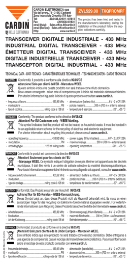
CARDIN ELETTRONICA spa
Via Raffaello, 36- 31020 San Vendemiano (TV) Italy
Tel:
+39/0438.404011-401818
Fax:
+39/0438.401831
email (Italy):
Sales.offi[email protected]
email (Europe):
Sales.offi[email protected]
Http:
www.cardin.it
CODICE
SERIE
MODELLO
DATA
ZVL282.04
S438
FM
21-09-2001
La serie S438 è conforme ai requisiti essenziali fissati dalla direttiva 99/
05/CE e ad esso sono state applicate le norme tecniche di riferimento.
Frequenza: 433,92 MHz per tutti i paesi
RADIOCOMANDO DIGITALE A CODICE PROGRAMMABILE S438
Descrizione
Il sistema di radiocomando S438 è composto da uno o più trasmettitori e da
uno o più ricevitori che saranno combinati in relazione alle esigenze specifiche
d'impianto. La codifica con dip-switch a 14 vie, che consente un numero di
combinazioni codici utente pari a 16384, ed il particolare protocollo di trasmissione non statico ma ciclico, rendono il sistema semplice nell'installazione e
sicuro nell'applicazione. Grazie al tipo di modulazione FM/FSK il sistema offre
maggiori prestazioni, in presenza di disturbi e rumore, rispetto ad un sistema
tradizionale con modulazione AM/ASK.
Possibilità d'impiego
Il radiocomando S438 permette l'attuazione a distanza di apparecchiature
elettriche ed elettroniche, trovando il suo migliore impiego nel comando di:
porte e portoni motorizzati, sistemi d'allarme ed in tutti gli impianti dove sia
richiesta l'attuazione a distanza (senza fili), nel rispetto delle norme di sicurezza
che regolano l'installazione.
Versioni trasmettitori
TRQ438200
Trasmettitori tascabili
TRQ438400
Trasmettitori tascabili
2 tasti
4 tasti
Versioni ricevitori
RMS438200
Rx mini con contenitore per uso interno
RSS438200
Rx a scheda ad innesto
2 relè
2 relè
Ricevitori a scheda (fig. 5)
Attenzione! La scheda va adeguatamente isolata dalle parti delle apparecchiature in cui viene incorporata e che si trovano a tensione di rete.
• il ricevitore (CS1031) viene inserito direttamente nell'apparecchiatura predisposta a riceverlo con collegamento elettrico:
12V ac-dc con jumper "J1" in posizione "B"
24V ac-dc con jumper "J1" in posizione "A"
Il ricevitore a scheda ha due relé le cui uscite sono contrassegnate rispettivamente con CH1 (solo contatto N.A.) e CH2 (contatto N.A.-N.C.). I relé CH1 e
CH2 possono essere attivati selezionando, con dei jumper situati sul circuito,
le funzioni A, B, C, D corrispondenti alle funzioni CHA, CHB, CHC, CHD del
trasmettitori (vedi fig. 3,4).
MOD: 02-04-2004
Ricevitori mini IP20 (fig.6)
• Il ricevitore (CS1031) è dotato di contenitore da interno e di morsettiera a 8
vie con collegamento elettrico:
12V ac-dc tra i morsetti 7-8.
24V ac-dc tra i morsetti 6-8.
Il ricevitore mini ha due relé le cui uscite sono contrassegnate rispettivamente
con CH1 (solo contatto N.A.) e CH2 (contatto N.A.-N.C.). I relé CH1 e CH2
possono essere attivati selezionando, con dei jumper situati sul circuito, le
funzioni A, B, C, D corrispondenti alle funzioni CHA, CHB, CHC, CHD del
trasmettitori (fig. 3,4).
Installazione ricevitore-antenna
Portata minima e massima dei radiocomandi.
Per portata si intende la distanza utile di funzionamento fra trasmettitore e
ricevitore con antenna installata, e misurata in spazio libero. La portata è quindi
strettamente legata alle caratteristiche tecniche del sistema (potenza e sensibilità)
e varia in base alle caratteristiche del luogo di postazione.
Per ottenere il funzionamento ottimale del radiocomando è bene scegliere
con attenzione i punti d'installazione del ricevitore e dell'antenna. Non è
consigliabile l'installazione di due ricevitori che non rispettino una distanza
minima di 1,5 m tra loro ed è buona norma posizionare il ricevitore a debita
distanza da reti di sistemi computerizzati, da impianti d'allarme e da altre fonti
di possibile disturbo.
(Sistemazioni anomale potrebbero comprometterne in parte il funzionamento)
Antenna
L'installazione dell'antenna è fondamentale; collegata al ricevitore rappresenta
il punto di ricezione del radiocomando. Nella sua installazione si rispettino le
seguenti indicazioni.
I ricevitori sono dotati di antenna propria, consistente in uno spezzone di filo
rigido, lungo 170mm.
In alternativa è possibile collegare l'antenna accordata ANS400 al ricevitore
mediante cavetto coassiale RG58 (impedenza 50Ω) di lunghezza max. 15m.
L'antenna va posizionata all'esterno nel punto più elevato e visibile, lontano
da strutture metalliche.
Impostazione del codice e selezione funzioni
Il codice deve essere impostato agendo sul dip-switch a 14 vie e deve essere
lo stesso sia sul trasmettitore che sul ricevitore. È consigliabile evitare l'impostazione banali cioè tutti gli switch in OFF o in ON.
La programmazione può essere effettuata più volte anche successivamente
all'installazione, con la conseguente possibilità di garantire la segretezza del
codice utente.
Trasmettitore
Nei trasmettitori ogni tasto corrisponde ad una diversa funzione, con la sola
eccezione del trasmettitore a due pulsanti ove al tasto di sinistra è associata
la funzione CHA mentre al tasto di destra è possibile associare una diversa
funzione agendo sul DIP a due vie (vedi fig. 3,4).
CARATTERISTICHE TECNICHE
Ricevitore
-
-
frequenza di ricezione ................................................................ 433,92 MHz
frequenza dell'oscillatore locale ...................................................... 418 MHz
tolleranza dell'oscillatore locale ....................................................... ±75 kHz
emissione dell'oscillatore locale.................................................... <-57 dBm
frequenza intermedia IF 1.................................................................. 16 MHz
frequenza intermedia IF 2....................................................................70 kHz
modulazione con ΔF
larghezza di banda (sezione RF) .........................................................25 kHz
larghezza di banda (bassa frequenza) ................................................10 kHz
impedenza di ingresso antenna .............................................................. 50Ω
sensibilità (per segnale a buon fine) .....................................................1.5 µV
alimentazione ricevitore mini ...................................................12/24V ac-dc
alimentazione ricevitore a scheda (selezione tramite J1) .......12/24V ac-dc
assorbimento a riposo......................................................................... 28 mA
assorbimento con relé attivato............................................................ 55 mA
massima potenza commutabile dal relé con carico resistivo:
carico in dc .............................................................................................24W
carico in ac ............................................................................................60VA
tensione massima ......................................................................... 30V ac-dc
ritardo all'attivazione del relè .............................................................. 150 ms
ritardo alla diseccitazione del relè ...................................................... 150 ms
temperatura di esercizio ............................................................-10°…+55°C
Trasmettitore
-
frequenza di trasmissione .......................................................... 433,92 MHz
tolleranza sulla frequenza di trasmissione ....................................... ±30 kHz
larghezza di banda .......................................................................... > 25 kHz
potenza apparente irradiata ............................... -10…-7 dBm (100-200µW)
potenza apparente dei prodotti armonici .........................<-54 dBm (<4nW)
modulazione ......................................................................................FM/FSK
modulazione con ΔF .......................................................................... ≤20 kHz
alimentazione (batteria alcalina GP23A) .......................................12V ±10%
assorbimento ....................................................................................... 25 mA
temperatura di esercizio ............................................................-10°…+55°C
umidità relativa..................................................................................... < 95%
antenna .............................................................................................Integrata
CARDIN ELETTRONICA spa
Via Raffaello, 36- 31020 San Vendemiano (TV) Italy
Tel:
+39/0438.404011-401818
Fax:
+39/0438.401831
email (Italy):
Sales.offi[email protected]
email (Europe):
Sales.offi[email protected]
Http:
www.cardin.it
SERIAL NUMBER
SERIES
MODEL
DATE
ZVL282.04
S438
FM
21-09-2001
The S438 series conforms to the essential requirements of the directive
99/05/CE and the technical reference standards have been applied.
Frequency validity: 433,92 MHz for all
Countries
DIGITAL RADIO CONTROLS WITH PROGRAMMABLE CODES S438 AT 433 MHz 'FM'
Description
The S438 radio control system consists of one or more transmitters and one or
more receivers which can be combined to meet the specific needs of the system.
The code setting method, using a 14-way dip-switch, allows up to 16348 user code
combinations and the type of transmission protocol (not static but cyclic) makes
the system easy to install and secure.
Thanks to the FM/FSK modulation the system gives greater performance when
faced with disturbance and noise with respect to a traditional system using AM/ASK
modulation.
Use
The S438 radio control allows the remote activation of electrical and electronic appliances with its best use in the following areas: automatic opening systems, alarm
systems, and in all systems which require remote control activation (without wires),
in compliance with the safety standards governing the installation of appliances.
Transmitter versions
TRQ438200
Miniaturised transmitters
TRQ438400
Miniaturised transmitters
Receiver versions
RMS438200
Mini box receiver for indoor use
RSS438200
Slot-in receiver card
2 Buttons
4 Buttons
2 Relays
2 Relays
Slot-in receiver cards (fig. 5)
Warning! The receiver cards must be sufficiently insulated from the parts of the
host device which are powered by the mains.
• The receiver card (printed circuit CS1031) is inserted directly into an appliance
which is designed to receive and has the following electrical connections:
12V ac-dc with jumper "J1" in position "B"
24V ac-dc with jumper "J1" in position "A"
The receiver cards are fitted with two relays, the outputs of which are marked CH1
(normally open contact) and CH2 (normally open/normally closed contact).
The relays CH1 and CH2 can be activated by selecting the functions A-B-C-D and
made to correspond with the transmitter channels CHA-CHB-CHC-CHD by setting
the jumpers situated on the circuit board (fig.3,4).
Mini receivers IP20 (fig .6)
• The mini receiver (printed circuit CS1031) is housed in an indoor container, it is fitted
with an 8-way terminal board and has the following electrical connections:
12V ac-dc between binding posts 7-8.
24V ac-dc between binding posts 6-8.
The mini receivers are fitted with two relays, the outputs of which are marked CH1
(normally open contact) and CH2 (normally open/normally closed contact).
The relays CH1 and CH2 can be activated by selecting the functions A-B-C-D and
made to correspond with the transmitter channels CHA-CHB-CHC-CHD by setting
the jumpers situated on the circuit board (fig.3,4).
Receiver antenna installation
Minimum and maximum range of the radio controls. "Range" is intended to mean the
working distance, measured in free space, between the receiver and the transmitter
with the antenna installed.
The range is therefore closely linked to the technical characteristics of the system
(power and sensibility) and varies according to the characteristics of the site in
which the system is located. It therefore follows that to obtain the best results from
the radio control the installation sites for the receiver and the antenna should be
carefully chosen.
You are not advised to install 2 receivers at a distance of less than 1,5 m from each
other and it is also good practise to position the receiver away from computer
systems, alarm systems and other possible sources of disturbance.
(A bad choice of positioning could compromise the correct performance of
the receiver).
Antenna
The installation of the antenna is fundamental, connected to the receiver it represents
the reception point for the radio control. When installing the antenna the following
points should be observed.
The receiver is supplied with its own antenna which consists of a piece of rigid
wire 170 mm in length.
In alternative it is possible to connect an ANS400 tuned antenna using a coaxial
cable RG58 (impedance 50Ω) with a maximum length of 15m.
The antenna should be positioned out of doors in the highest possible point, visible
and away from metal structures.
Setting the user code and selecting functions
The code is set by means of the 14-way dip-switch and must be the same in both
the transmitter and the receiver. You are advised to avoid setting obvious combinations such as all the dips in "OFF" or all the dips in "ON".
Programming can be carried out after installation whenever required thus allowing
you to constantly maintain a secret user code.
Transmitters
In the transmitters each button corresponds to a different function with the sole
exception of the two button transmitter where the left hand button is associated
with the function CHA and the right hand button can be associated with a different
function by setting the 2-way dip (see fig. 3,4).
TECHNICAL SPECIFICATIONS
Receiver
- reception frequency...........................................................................433,92 MHz
- local oscillation frequency .....................................................................418 MHz
- local oscillation tolerance ........................................................................ ±75 kHz
- local oscillation emission ...................................................................... <-57 dBm
- intermediate frequency IF 1......................................................................16 MHz
- intermediate frequency IF 2....................................................................... 70 kHz
- modulated with ΔF
bandwidth (radio frequency section) ......................................................... 25 kHz
bandwidth (low frequency) ........................................................................ 10 kHz
- antenna impedance in input ...........................................................................50Ω
- sensitivity (finely tuned signal) .................................................................... 1.5 µV
- mini receiver power supply ............................................................12/24V ac-dc
- slot-in card power supply (selected via jumper J1) .......................12/24V ac-dc
- maximum power consumption at rest ....................................................... 28 mA
- maximum power consumption with activated relay .................................. 55 mA
- maximum commutable power at the relay
with resistive load:
load dc .......................................................................................................... 24W
load ac ......................................................................................................... 60VA
maximum voltage ................................................................................30V ac-dc
- relay activation time...................................................................................150 ms
- relay dropout delay ....................................................................................150 ms
- operating temperature range ...........................................................-10°…+55°C
Transmitters
- carrier frequency................................................................................433,92 MHz
- carrier frequency tolerance ..................................................................... ±30 kHz
- band width ............................................................................................... >25 kHz
- apparent radiated power ............................................ -10…-7dBm (100-200µW)
- apparent power harmonic products ........................................<-54 dBm (<4nW)
- modulation ............................................................................................... FM/FSK
- modulated with ΔF.................................................................................... ≤20 kHz
- power supply (alkaline battery GP23A) .............................................. 12V ± 10%
- maximum power consumption .................................................................. 25 mA
- operating temperature range ............................................................ -10…+55°C
- relative humidity..........................................................................................< 95%
- antenna ................................................................................................. Integrated
CARDIN ELETTRONICA spa
Via Raffaello, 36- 31020 San Vendemiano (TV) Italy
Tel:
+39/0438.404011-401818
Fax:
+39/0438.401831
email (Italy):
Sales.offi[email protected]
email (Europe):
Sales.offi[email protected]
Http:
www.cardin.it
FASCICULE
SERIE
MODEL
DATA
ZVL282.04
S438
FM
21-09-2001
La série S438 répond aux conditions essentielles requises par la directive
99/05/CE et a été réalisée selon les normes techniques de référence.
Fréquenza: 433,92 MHz per les pays
TÉLÉCOMMANDE DIGITALE ÀVEC CODE PROGRAMMABLE S438 À 433 MHz 'FM'
Description
Le système de télécommande radio S438 est constitué d'un ou de plusieurs
émetteurs et d'un ou de plusieurs récepteurs, qui seront combinés en fonction des
exigences spécifiques de l'installation. Le codage par dip-switch à 14 voies permettant un nombre de combinaisons de l'ordre de 16384 et le protocole particulier de
la transmission, non statique mais cyclique, rendent ce système simple à installer
et sûr lors de l'application. Grâce au type de modulation FM/FSK, le système offre
des performances plus hautes que celles d'un système traditionnel à modulation
AM/ASK en cas de parasites et de bruits.
Possibilités d'emploi
La télécommande radio S438 permet de commander à distance des appareils
électriques et électroniques et offre un grand éventail d'utilisation dans la commande
de fermetures automatisées, systèmes d'alarme et dans toutes les installations qui
nécessitent une commande à distance (sans fil) dans le respect des normes de
sécurité qui réglementent l'installation.
Versions émetteurs
TRQ438200
Émetteurs de poche
TRQ438400
Émetteurs de poche
Versions récepteurs
RMS438200 Mini récepteur sous boîtier pour l'intérieur
RSS438200
Récepteur à carte
2 touches
4 touches
2 relais
2 relais
Récepteur à carte (fig.5)
Attention! La carte doit être adéquatement isolée des parties de l’appareil qui la
reçoit, en raison du fait que celles-ci sont sous tension.
• Le récepteur (CS1031) est embroché directement sur l'appareil prédisposé à le
recevoir, avec connexion électrique:
12V ac-dc avec cavalier "J1" en position "B"
24V ac-dc avec cavalier "J1" en position "A"
Le récepteur à carte a deux relais, les sorties étant marquées respectivement de
CH1 (seulement contact N.O.) et de CH2 (contact N.O. - N.F.). Les relais CH1 et
CH2 peuvent être activés en sélectionnant, à travers les cavaliers qui se trouvent
sur le circuit, les fonctions A, B, C, D correspondant aux fonctions CHA, CHB, CHC,
CHD des émetteurs (fig.3,4).
Mini récepteurs IP20 (fig.6)
• Le récepteur (CS1031) est doté de boîtier pour l'intérieur et de bornier à 8 voies
avec connexion électrique:
12V ac-dc entre les bornes 7-8.
24V ac-dc entre les bornes 6-8.
Le mini récepteur a deux relais, les sorties étant marquées respectivement de CH1
(seulement contact N.O.) et de CH2 (contact N.O. - N.F.). Les relais CH1 et CH2
peuvent être activés en sélectionnant, à travers les cavaliers qui se trouvent sur le
circuit, les fonctions A, B, C, D correspondant aux fonctions CHA, CHB, CHC, CHD
des émetteurs (fig. 3,4).
Installation récepteur-antenne
Portée minimum et maximum des télécommandes radio:
Par portée, nous entendons la distance nécessaire au fonctionnement, entre émetteur
et récepteur avec antenne installée et mesurée en espace libre. La portée est donc
strictement liée aux caractéristiques techniques du système (puissance et sensibilité)
et varie en fonction des caractéristiques du lieu d'emplacement.
Pour obtenir un fonctionnement optimal de la télécommande radio, il est important
de choisir soigneusement les endroits pour l'installation du récepteur et de l'antenne.
En cas d'installation de deux récepteurs, respecter impérativement une distance
minimale de 1,5 m entre les deux. Il est conseillé de positionner le récepteur à une
juste distance des réseaux avec système à ordinateurs, d'installations d'alarme ou
autres qui pourraient provoquer des perturbations.
(Des positionnements inadéquats pourraient compromettre en partie le fonctionnement).
Antenne
L'installation de l'antenne est fondamentale; une fois branchée au récepteur, elle
représente le point de réception de la télécommande radio.
Pour son installation, observer les indications suivantes.
Le récepteur est équipé d'une propre antenne qui consiste en un morceau de fil
rigide d'une longueur de 170mm.
En alternative, il est possible de brancher l'antenne accordée ANS400 au moyen
d'un câble coaxial RG58 (impédance 50Ω) d'une longueur maxi. de 15m.
L'antenne doit être positionnée à l'extérieur, sur le point le plus élevé et visible, loin
de toute structure métallique.
Programmation du code et sélection des fonctions
Le code doit être programmé par l'intermédiaire du dip-switch à 14 voies. Il est
indispensable que le code de l'émetteur corresponde à celui du récepteur.
Il est conseillé de ne pas faire de programmations banales, c'est-à-dire tous les
interrupteurs sur OFF ou sur ON. Pour garantir le secret du code usager, la programmation peut être faite plusieurs fois même après l'installation.
Emetteur
Dans les émetteurs, chaque touche correspond à une fonction différente, à l’exception de l’émetteur à deux touches où la touche de gauche est associée à la fonction
CHA, tandis que la touche de droite peut être affectée à une fonction différente en
intervenant sur le DIP à deux voies (voir fig. 3,4).
CARACTÉRISTIQUES TECHNIQUES
Récepteur
- fréquence de réception ....................................................................... 433,92 MHz
- fréquence de l'oscillateur local ................................................................ 418 MHz
- tolérance de l'oscillateur local .................................................................. ±75 kHz
- émission de l'oscillateur local ................................................................ <-57 dBm
- fréquence intermédiaire IF 1 ...................................................................... 16 MHz
- fréquence intermédiaire IF 2 ........................................................................70 kHz
- modulation avec ΔF
largeur de la bande (section RF) ..................................................................25 kHz
largeur de la bande (basse fréquence) ........................................................10 kHz
- impédance d'entrée antenne ........................................................................... 50Ω
- sensibilité (signal de bonne réussite) ............................................................1.5 µV
- alimentation mini récepteur .............................................................12/24V ac-dc
- alimentation récepteur a carte (sélection à travers J1) ...................12/24V ac-dc
- absorption au repos ..................................................................................... 28 mA
- absorption avec relais activé ....................................................................... 55 mA
- puissance maximum commutable relais
avec charge résistive:
charge en dc ....................................................................................................24W
charge en ac ...................................................................................................60VA
tension maximum .................................................................................. 30V ac-dc
- retard à l'excitation ......................................................................................150 ms
- retard à la désexcitation ..............................................................................150 ms
- température de fonctionnement ........................................................-10°…+55°C
Émetteurs
- fréquence porteuse ............................................................................. 433,92 MHz
- tolérance de la fréquence porteuse .......................................................... ±30 kHz
- largeur de bande ....................................................................................... >25 kHz
- puissance apparente irradiée ...................................... -10…-7dBm (100-200µW)
- puissance apparente des produits harmoniques......................<-54 dBm (<4nW)
- modulation..................................................................................................FM/FSK
- modulation avec ΔF ...................................................................................≤20 kHz
- alimentation (batterie alcaline GP23A)..................................................12V ± 10%
- absorption .................................................................................................... 25 mA
- température de fonctionnement ........................................................-10°…+55°C
- humidité relative ........................................................................................... < 95%
- antenne .........................................................................................................intégré
CARDIN ELETTRONICA spa
Via Raffaello, 36- 31020 San Vendemiano (TV) Italy
Tel:
+39/0438.404011-401818
Fax:
+39/0438.401831
email (Italy):
Sales.offi[email protected]
email (Europe):
Sales.offi[email protected]
Http:
www.cardin.it
ART.-NR.
SERIE
MODELL
DATUM
ZVL282.04
S438
FM
21-09-2001
Die Serie S438 entspricht den von der Bestimmung 99/05/CE festgelegten grundsätzlichen
Anforderungen und bei ihr wurden die technischen Bezugsnormen angewandt.
Frequenzbereich: 433.92 für alle Länder der
DIGITALE FUNKSTEUERUNG MIT PROGRAMMIEREN CODENUMMERN 433 MHz 'FM'
Beschreibung
Das Funksteuerungssystem S438 besteht aus einem oder mehreren Sendern und aus
einem oder mehreren Empfängern, die gemäß den spezifischen Anforderungen der
Anlage kombiniert werden. Die Kodifizierung mit dem 14-Wege-Dip-Switch, welcher
16384 Anwendercodekombinationsmöglichkeiten bietet, und das besondere, nicht
statische sondern zyklische Übertragungsprotokoll gestalten die Installation des
Systems einfach und machen dessen Anwendung sicher. Dank des Modulationstyps
FM/FSK bietet das System bei Störungen und Rauschen im Vergleich zu einem
herkömmlichen System mit der Modulation AM/ASK eine bessere Leistung.
Anwendungsmöglichkeiten
Die Funksteuerung S438 ermöglicht die Fernbedienung elektrischer und elektronischer
Geräte und findet beste Anwendung bei der Steuerung automatischer Öffnungssysteme, Alarmsystemen und bei allen Anlagen, bei denen die Inbetriebsetzung durch
Fernbedienung (ohne Drähte) verlangt wird. Sie ist durch einen hochzuverlässigen
Geheimcode unter Beachtung der für die Installation geltenden Sicherheitsnormen
geschützt.
Sender-Versionen
TRQ438200 Handsender
TRQ438400 Handsender
2 Tasten
4 Tasten
Empfänger-Versionen
RMS438200 Miniempfänger
RSS438200 Steckempfänger
2 Relais
2 Relais
Steckempfänger (Abb. 5)
Achtung! Die Karte muss in angemessener Weise gegenüber den Teilen der
Apparatur, in die sie eingebaut wird und die sich unter Netzspannung befinden,
isoliert werden.
• Der Steckempfänger (CS1031) wird direkt in die Apparatur eingesetzt, die zu
dessen Aufnahme komplett mit dem elektrischen Anschluss vorbereitet ist:
12V ac-dc mit Jumper "J1" in Position "B".
24V ac-dc mit Jumper "J1" in Position "A".
Die Empfängerkarte verfügt über zwei Relais, deren Ausgänge entsprechend mit
CH1 (nur Einschaltglied-Kontakte) und CH2 (Einschaltglied-/Ausschaltglied-Kontakte)
gekennzeichnet sind. Die Relais CH1 und CH2 können durch Wahl der Funktionen
A, B, C, D, welche den Funktionen CHA, CHB, CHC, CHD der Sender entsprechen,
mittels der auf dem Schaltkreis befindlichen Jumper aktiviert werden (Abb. 3,4).
Miniempfänger IP20 (Abb. 6)
• Der Empfänger (CS1031) ist mit einem Gehäuse zur Innenanwendung und mit
einer 8-Wege-Klemmleiste mit elektrischem Anschluss ausgestattet:
12V ac-dc zwischen den Klemmen 7-8
24V ac-dc zwischen den Klemmen 6-8.
Der Miniempfänger verfügt über zwei Relais, deren Ausgänge entsprechend mit CH1
(nur Einschaltglied-Kontakte) und CH2 (Einschaltglied-/Ausschaltglied-Kontakte)
gekennzeichnet sind. Die Relais CH1 und CH2 können durch Wahl der Funktionen
A, B, C, D, welche den Funktionen CHA, CHB, CHC, CHD der Sender entsprechen,
mittels der auf dem Schaltkreis befindlichen Jumper aktiviert werden (Abb. 3,4).
Installation Empfänger - Antenne
Mindest- und Höchstreichweite der Funksteuerungen:
Unter Reichweite versteht sich der nutzbare Betriebsabstand zwischen Sender und
Empfänger, deren Antenne im freien Raum installiert und gemessen wurde. Daher
steht die Reichweite in unmittelbarem Zusammenhang mit den technischen Eigenschaften des Systems (Leistung und Ansprechempfindlichkeit) und verändert sich
entsprechend dem Aufstellungsort. Um einen optimalen Betrieb der Funksteuerung
zu gewährleisten, sind die Installationsorte für den Empfänger und die Antenne
sorgfältig auszuwählen. Die Installation von zwei Empfängern, zwischen denen kein
Mindestabstand von 1,5 m eingehalten wird, ist nicht möglich.
Es ist ratsam, den Empfänger in gebührendem Abstand zu Computersystemen,
Alarmanlagen und anderen möglichen Störungsquellen aufzustellen.
(Eine unsachgemäße Aufstellung könnte den Betrieb teilweise gefährden).
Antenne
Die Installation der Antenne ist von äußerster Wichtigkeit; nachdem sie mit dem
Empfänger verbunden ist, stellt sie den Empfangspunkt für die Funksteuerung dar.
Bei ihrer Installation ist folgendes zu beachten.
Die Empfängerkarte ist mit einer eigenen Antenne ANS400 ausgestattet, die aus
einem Stück Draht besteht, der 170mm lang ist. Alternativ kann eine passende
Antenne verwendet werden, die mittels einem Koaxialkabel RG58 (Impedanz 50Ω)
mit einer maximalen Länge von 15m an den Empfänger angeschlossen wird. Die
Antenne wird im Freien am höchsten und sichtbarsten Punkt von Metallstrukturen
entfernt, positioniert.
Einstellung des Codes und Funktionenwahl
Der Code muss mittels des 14-Wege-Dip-Switch eingestellt werden und sollte
sowohl auf dem Sender wie auch auf dem Empfänger identisch sein.
Es ist ratsam banale Einstellungen, wie z.B. alle Switch in OFF-oder ON-Stellung, zu
vermeiden. Die Programmierung kann zur Gewährleistung der Geheimhaltung des
Anwendercodes mehrmals auch nach erfolgter Installation ausgeführt werden.
Handsender
Bei den Sendern entspricht jede Taste einer anderen Funktion, einzigste Ausnahme
der Sender mit zwei Tasten, bei dem der linken Taste die CHA-Funktion zugeordnet
wurde, während der rechten Taste eine andere Funktion mittels des 2-Wege-DIP
zugeordnet werden kann (siehe Abb. 3,4).
TECHNISCHE DATEN
EMPFÄNGER
- Empfangsfrequenz .............................................................................433,92 MHz
- Örtlichen Frequenz .................................................................................418 MHz
- Abweichung von der örtlichen Frequenz ............................................... ±75 MHz
- Emission der örtlichen Frequenz ..........................................................<-57 dBm
- Zwischenfrequenz IF 1..............................................................................16 MHz
- Zwischenfrequenz IF 2...............................................................................70 kHz
- Modulation mit ΔF
- Bandbreite (Bereich RF) .............................................................................25 kHz
- Bandbreite (Niederfrequenz) ......................................................................10 kHz
- Eingangsimpedanz Antenne .......................................................................... 50Ω
- Ansprechempfindlichkeit (eines erfolgreichen Signals) ..............................1.5 µV
- Stromversorgung Miniempfänger ................................................... 12/24V ac-dc
- Stromversorgung Empfängerkarte (mittels J1 wählbar) ................. 12/24V ac-dc
- Ruhebedarf .................................................................................................28 mA
- Bedarf bei aktiviertem Relais ......................................................................55 mA
- vom Relais umschaltbare Höchstleistung mit Belastungswiderstand:
Belastung bei Gleichstrom ............................................................................24W
Belastung bei Wechselstrom .......................................................................60VA
Höchstspannung ................................................................................ 30V ac-dc
- Verzug der Erregung ................................................................................. 150 ms
- Verzug der Aberregung ............................................................................. 150 ms
- Betriebstemperatur ......................................................................... - 10°…+55°C
SENDER
- Trägerfrequenz ....................................................................................433,92 MHz
- Abweichung von der Trägerfrequenz.......................................................± 75 kHz
- Bandbreite ...............................................................................................> 25 kHz
- Scheinstrahlungsleistung ............................................ -10…-7dBm (100-200µW)
- Scheinleistung der harmonischen Produkte............................. <-54 dBm (<4nW)
- Modulation................................................................................................FM/FSK
- Modulation mit ΔF ...................................................................................≤20 kHz
- Versorgung (alkalische Batterie GP23A) .............................................. 12V ± 10%
- Bedarf ..........................................................................................................25 mA
- Betriebstemperatur.......................................................................... - 10°…+55°C
- Relative Feuchtigkeit .................................................................................. < 95%
- Antenne ..................................................................................................... ergänzt
CARDIN ELETTRONICA spa
Via Raffaello, 36- 31020 San Vendemiano (TV) Italy
Tel:
+39/0438.404011-401818
Fax:
+39/0438.401831
email (Italy):
Sales.offi[email protected]
email (Europe):
Sales.offi[email protected]
Http:
www.cardin.it
CODIGO
SERIE
MODELO
FECHA
ZVL282.04
S438
FM
21-09-2001
La serie S438 es conforme con los requisitos esenciales dispuestos por la
directiva 99/05/CE y con ésta se relacionan las normas técnicas de referencia.
Frecuencia: 433,92 MHz para los países de l
RADIOMANDO DIGITAL POR CODIGOS PROGRAMMABLE 433 MHz 'FM'
Descripción
El sistema de radiomando S438 consta de uno o más transmisores y de uno o
más receptores que se combinarán en función de las exigencias específicas de
la instalación. La codificación con dip-switch de 14 vías, que consiente 16384
combinaciones del código del usuario, y en especial el protocolo de transmisión
no estático sino cíclico, vuelven el sistema fácil de instalar y seguro durante su
funcionamiento. Gracias al tipo de modulación FM/FSK el sistema ofrece más
prestaciones, ante los parásitos y el ruido, con respecto a un sistema convencional
con modulación AM/ASK.
Antena
La instalación de la antena es fundamental; conectada al receptor representa el
punto de recepción del radiomando.
Durante su instalación hay que cumplir las instrucciones siguientes.
El receptor con tarjeta está dotado de antena propia, que consta de un trozo de hilo
rígido, de 170 mm de largo. En alternativa es posible utilizar una antena acordada
a conectar al receptor mediante un cable coaxial RG58 (imp. 50Ω) de 15m de largo
como máximo. La antena se debe colocar al exterior en el sitio más elevado y visible,
lejos de estructuras metálicas.
Posibilidad de empleo
El radiomando S438 permite la activación a distancia de equipos eléctricos y electrónicos, y su mejor utilización consiste en el mando de aperturas automatizadas,
sistemas de alarma y en todas las instalaciones donde se requiere la activación a
distancia (inalámbrica) protegida por un código secreto de gran fiabilidad cumpliendo
con las normas de seguridad que rigen para la instalación.
Programación del código y selección de las funciones
El código se tiene que programar actuando sobre el dip-switch de 14 vías y debe
ser el mismo tanto para el transmisor como para el receptor.
Se aconseja evitar la programación más corriente, o sea todos los switch en OFF
o en ON.
La programación se puede realizar más veces aun después de la instalación, para
poder garantizar el código secreto del usuario.
Modelos de transmisores
TRQ438200 Transmisores de bolsillo
TRQ438400 Transmisores de bolsillo
Modelos de receptores
RMS438200 Minirreceptor con contenedor para uso interior
RSS438200 Receptor con tarjeta
2 teclas
4 teclas
2 relé
2 relé
Transmisor
En los transmisores cada tecla corresponde a una función diferente, exceptuando
únicamente el transmisor con dos botones donde la tecla de la izquierda está acoplada con la función CHA mientras que la de la derecha se puede acoplar con una
función diferente actuando sobre el DIP de dos vías (ver fig. 3,4).
CARACTERISTICAS TECNICAS
Receptor con tarjeta (fig. 5)
¡Cuidado! La tarjeta se tiene que aislar oportunamente de las piezas del aparato al
que se la incorpora y que se encuentran sometidas a la tensión de red.
• El receptor (CS1031) se conecta directamente con el equipo predispuesto a tal
fin mediante conexión eléctrica:
12V ac-dc con el jumper "J1" en la posición "B";
24V ac-dc con el jumper "J1" en la posición "A".
El receptor con tarjeta tiene dos relés cuyas salidas están marcadas respectivamente
con CH1 (sólo contacto N.A.) y CH2 (contacto N.A. - N.C.).
Los relés CH1 y CH2 se pueden activar seleccionando, por medio de unos jumpers
situados en el circuito, las funciones A, B, C, D correspondientes a las funciones
CHA, CHB, CHC, CHD de los transmisores (fig. 3,4).
Mini-receptor IP20 (fig. 6)
• El receptor (CS1031) está dotado de contenedor para el interior y de bornera de
8 vías con conexión eléctrica:
12V ac-dc entre los bornes 7-8.
24V ac-dc entre los bornes 6-8.
El mini-receptor tiene dos relés cuyas salidas están marcadas respectivamente con
CH1 (sólo contacto N.A.) y CH2 (contacto N.A. - N.C.).
Los relés CH1 y CH2 se pueden activar seleccionando, por medio de unos jumpers
situados en el circuito, las funciones A, B, C, D correspondientes a las funciones
CHA, CHB, CHC, CHD de los transmisores (fig. 3,4).
Instalación receptor-antena
Alcance mínimo y máximo de los radiomandos:
Por alcance se entiende la distancia útil de funcionamiento entre el transmisor y el
receptor con la antena instalada y medida al aire libre.
Por tanto el alcance depende de las características técnicas del sistema (potencia y
sensibilidad) y varía en función de las características del lugar de emplazamiento.
Para obtener el mejor funcionamiento del radiomando es necesario elegir con sumo
esmero los sitios de instalación del receptor y de la antena.
No es posible efectuar la instalación de dos receptores que no tengan la distancia
mínima de 1,5 m entre sí. Es buena regla colocar el receptor a cierta distancia de
las redes de sistemas computarizados, instalaciones de alarma y otras fuentes de
perturbaciones posibles.
(Su colocación incorrecta podría perjudicar parcialmente al funcionamiento).
RECEPTOR
- frecuencia de recepción ....................................................................... 433,92 MHz
- frecuencia del oscilador local .................................................................... 418 MHz
- tolerancia de la frecuencia del oscilador local ........................................... ±75 kHz
- emisión del oscilador local ...................................................................... <-57 dBm
- frecuencia intermedia IF 1 ........................................................................... 16 MHz
- frecuencia intermedia IF 2 .............................................................................70 kHz
- modulación con ΔF
- ancho de banda (sección RF) .......................................................................25 kHz
- ancho de banda (baja frecuencia) .................................................................10 kHz
- impedancia de entrada antena ......................................................................... 50Ω
- sensibilidad (para señal a buen fin) ................................................................1,5 µV
- alimentación receptor mini .................................................................12/24V ac-dc
- alimentación receptor con tarjeta (selección mediante J1) ..............12/24V ac-dc
- absorción descanso ...................................................................................... 28 mA
- Absorción relé excitado ................................................................................. 55 mA
- potencia máxima conmutable del relé con carga resistiva:
carga en dc .......................................................................................................24W
carga en ac ......................................................................................................60VA
tensión máxima ...................................................................................... 30V ac-dc
- retraso a la excitación...................................................................................150 ms
- retraso a la desexcitación.............................................................................150 ms
- temperatura de funcionamiento ..........................................................-10°…+55°C
TRANSMISOR
- frecuencia portadora ............................................................................ 433,92 MHz
- tolerancia de la frecuencia portadora ........................................................ ±30 kHz
- amplitud de la banda ................................................................................. > 25 kHz
- potencia aparente irradiada .......................................... -10…-7dBm (100-200µW)
- potencia aparente de los productos armónicos .........................<-54 dBm (<4nW)
- modulación ..................................................................................................FM/FSK
- modulación con ΔF...................................................................................... ≤20 kHz
- alimentación (batería alcalina GP23A) ...................................................12V ± 10%
- absorción ....................................................................................................... 25 mA
- temperatura de funcionamiento .......................................................... - 10…+55°C
- humedad relativa ........................................................................................... < 95%
- antena ........................................................................................................integrado
DIMENSIONI D'INGOMBRO - OVERALL DIMENSIONS
DIMENSIONS D'ENCOMBREMENT - AUSSENABMESSUNGEN
DIMENSIONES DEL ESPACIO OCUPADO
IMPOSTAZIONE DEL CODICE UTENTE
NEI TRASMETTITORI A DUE CANALI
1
4
SETTING THE USER CODE IN 2 CHANNEL
rights reserved. Unauthorised copying or use of the information contained in this document is punishable by law
PROGRAMMAZIONE DU CODE USAGER
SUR LES ÉMETTEURS 2 CANAUX
39
80
PROGRAMMIERUNG DES ANWENDERCODES
BEI DEN FUNKSTEURUNG MIT ZWEI KANÄLEN
12
PROGRAMACION DEL CODIGO DEL USUARIO
EN LOS RADIOCOMANDOS DE LOS TECLAS
CAMBIO BATTERIA - CHANGING THE BATTERY
REMPLACEMENT DE LA PILE - BATTERIEWECHSEL
SUSTITUCIÓN DE LA PILA
CH-A-B-C-D
SELEZIONABILE
2
1
CH-A
FISSO
1
2
CH-A
2
CH-B
2
CH-C
2
CH-D
KA
L
IN
E
eserved. Unauthorised
copying :orDM0153
use of the information
in this
document isd'ingombro
punishable
All contained
rights reserved.
Unauthorised
copying or by
uselaw
of the information contained in this document is punishable by law
Description
: Dimensioni
Drawing number
Draft : P.J.Heath
S435
AL
Product Code : S435
1
Date : 02-07-2001
1 2
CARDIN ELETTRONICA S.p.A - 31020 San Vendemiano (TV) Italy - via Raffaello, 36 Tel: 0438/401818 Fax: 0438/401831
1
AL
KA
LIN
2
1
3
4
5
6
7
1 2 3 4 5 6 7 8
1 1 1 1 1
9 0 1 2 3 4
2
8
E
ON
ON
_ BATTERIA 12V
1
+
All rights reserved. Unauthorised copying or use of the information contained in this document is punishable by law
SELEZIONE DEI CANALI - CHANNEL SELECTION
DISPOSITION DES CANAUX - ANORDNUNG DER KANÄNE
DISPOSICION DE LOS CANALES
CH
CH
A
CH
B
A
CH
B
CH
ing number : DM0217
Description : Cambia batteria
uct Code : S438
S438
: P.J.Heath
3
All rights reserved. Unauthorised copying or use of the information contained in this document is punishable by law
CH
D
C
Description : Selezioni canali
Drawing number : DM0216
Date : 03-01-97
TX-S438
IN ELETTRONICA S.p.A - 31020 San Vendemiano (TV) Italy - via Raffaello, 36 Tel: 0438/401818 Fax: 0438/401831
Product Code : S438
RICEVITORE A SCHEDA AD INNESTO DIRETTO
SLOT-IN RECEIVER CARD
RÉCEPTEUR À CARTE EMBROCHABLE
STECKEMPFÄNGER
RECEPTOR CON TARJETA DE INSERCION DIRECTA
5
e : S435
Description : Disposizioni canali (TX 4ch)
ProductJ2
Code : S435
S435 CHANNEL SELECTION
S435
Draft : P.J.Heath
Date : 16-04-97
1 2 3 4 5 6 7 8
1 1 1 1 1
9 0 1 2 3 4
CHANNEL SELECTION
CH-2
CH-2
Date : 16-04-97
CS1031
DC0264
1 2 3 4 5 6 7 8
ON
1 1 1 1 1
Description : Disposizioni
(TX
9 0 Drawing
4 2ch)
2 3number
1 canali
: DM0260
ON
CH-A CH-B CH-C CH-D
6
MINI RECEIVER
MINI RÉCEPTEUR
MINIEMPFÄNGER
MINIRECEPTOR
CARDIN ELETTRONICA S.p.A - 31020 San Vendemiano (TV) Italy - via Raffaello, 36 Tel: 0438/401818 Fax: 0438/401831
CS1031
mber : DM0261
eath
MINI
Date : 03-02-97
Draft : P.J.Heath RICEVITORE
DC0265
ON
ON
J2
CH-A CH-B CH-C CH-D
TRONICA S.p.A - 31020 San Vendemiano (TV) Italy - via Raffaello,
Tel: 0438/401818
Fax:
0438/401831
CARDIN36
ELETTRONICA
S.p.A
- 31020
San Vendemiano (TV) Italy - via Raffaello, 36 Tel: 0438/401818 Fax: 0438/401831
CH-1
.A
s
Po
RF MODULE 433 MHz in FM
Relay
s.
Po
J1 12/24V
11 12
Relay
B
Drawing number : DC0264
7
6
5 4
3 2
NA
10 9 8
CH1
Relay
1
2
3
4
Description : Ricevitore a scheda
5
6
7
8
9 10
Antenna filo rigido 17cm
17 cm rigid wire antenna
Antenne fil rigide 17 cm
Starres Antennen Kabel 17 cm
Antena cable rígido 17 cm.
24V 12V 0
0V
CH2
1
Not
connected
12-24V
12V
RF MODULE 433 MHz in FM
Relay
24V
J1
CH-1
CH2
OUT
CH1
OUT
Alimentazione
Power supply
Antenna filo rigido 17cm
17 cm rigid wire antenna
Antenne fil rigide 17 cm
Starres Antennen Kabel 17 cm
Antena cable rígido 17 cm.
Scaricare