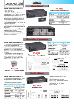
The Popular "Handy Mains" Inverter Series
The "Handy Mains" series of inverters produce AC mains power from a broad range of battery inputs and
some models have now been in production for over 10 years. We have a wealth of experience with inverters
and our designs reflect this, during their life time they have constantly evolved to meet the challenge of
powering most types of equipment, modern and old. With sales to five major distributors the "Handy
Mains" has become one of the foremost inverters in the field.
With power ranges up to 2700W there is sure to be a "Handy Mains" to suit your requirements.
Go to http://www.custompsudesign.com for more information.
___________________________________________________________________________________________________________________________________________
SMET Limited.
Registered in England & Wales, Number 6760677.
Registered .Office: Bell House, Ashford Hill Road, Ashford Hill, Berks. RG19 8BB.
VAT No. (GB) 944 0645 24
______________________________________________________________________________________________________________________________________________________________
CUSTOM POWER DESIGN
ELECTRONICS CONSULTANTS PROVIDING CUSTOM DESIGN, DEVELOPMENT, TEST & SUPPORT
______________________________________________________________________________________________________________________________________________________
Tel: + 44 (0)118 930 2299
A DIVISION OF SMET LTD
Fax: +44 (0)118 930 2206
______________________________________________________________________________________________________________________________________________________________
www.custompsudesign.com
Unit 19, The Markham Centre, Station Road, Theale, Berks. RG7 4PE.
[email protected]
400 WATT ‘HANDY MAINS’, 115VAC 400Hz OUTPUT.
WARNING: NOT SUITABLE FOR USE IN AIRCRAFT.
NOW WITH FRONT PANEL ON/OFF SWITCH (STILL HAS REMOTE ON/OFF FUNCTION).
SOCKET
OUTPUT
12V INPUT
SM3440
24V INPUT
36V INPUT
SM3441
SM3442
IEC (400W)
115V 400Hz 400W
ACCESSORIES:
SM 2793 Heavy Duty Wiring Kit, 2 metres long, for easy battery connection.
HIGH VOLTAGES EXIST IN THIS EQUIPMENT. TREAT AS HOUSE MAINS.
GENERAL: Small wall mounting inverters, generating mains level voltage, capable of powering most equipment from
12, 24 or 36 volt battery systems (model specific). Units with other input and output voltages are available. Note that
only heavy duty (high discharge rate) batteries are suitable (so called ‘leisure batteries’ are unlikely to be able to supply
sufficient current without excessive voltage drop). The output is a stepped AC quasi sine wave of nominally 115V RMS
400Hz..
The specification allows for up to 400W at 400Hz of continuous power to be taken, with 450W at 400Hz for up to 5
minutes. New ‘POWER PUSH’ © surge handling usually allows operation of equipment drawing a starting surge of
over 3 kilowatts. Because the output waveform contains high order harmonics, any Live to Neutral capacitance, such as
is found in equipment mains filters, causes a reduction in conversion efficiency. Use of the Handy Mains is therefore
limited to equipment having less than 0.47uF direct Line to Neutral capacitance. Power factor correction capacitors
must be removed from fluorescent lights. A filter is available for capacitive loads.
The battery input is via flat 5 mm screw terminals mounted under the raised body of the unit. The outlet socket earth pin
connects to case and a case grounding terminal is provided. The output is ohmically isolated via a safety barrier from
the input.
On 12 volt systems, the input current drawn is about 1 amp per 10W of final load, 24V systems take 0.5A per 10W and
36V systems take 0.33A per 10W.
A front panel on/off switch is fitted. The unit may however be turned off and on remotely by a low current control input
to the 2.8mm spade terminal. Connecting battery positive to this input turns on the output voltage. This connection
overrides the front panel switch setting when connected to battery positive, turning the unit on (set front panel switch to
OFF position for full remote control). A small switch may be used as the source for the control voltage. Note that the
unit does not draw battery current when turned off.
An audible warning indicates when the battery is becoming discharged. The tone becomes louder as the battery is
progressively discharged, prompting the user to recharge the battery. The unit latches off if the input voltage falls too
low (latch-off may be disabled by changing an internal jumper, call technical enquiries on +44 (0)118 930 2299).
INSTALLATION:
Connection: Refer to Diagram. 400W 400Hz HANDY MAINS units have 5mm threaded terminals for battery
connection on the raised underside of the unit under a protective cover. Appropriate mating ring terminals are packed
with the unit. The on/off input is via a small spade for which a mating half is also supplied. Wire of at least 12mm2
cross section (metal conductor diameter about 5mm) must be used for the battery. See above for recommended Heavy
Duty Wiring Kit, part No. SM2793. The inverter should be mounted close to the battery. Be sure to refit the insulated
protective cover for the terminals.
Document 3440E996, Issue 2.
___________________________________________________________________________________________________________________________________________
SMET Limited.
Registered in England & Wales, Number 6760677.
Registered .Office: Bell House, Ashford Hill Road, Ashford Hill, Berks. RG19 8BB.
VAT No. (GB) 944 0645 24
Pos
+
+ I/P
Switch
Output
on/off
Battery
Connection.
Neg
_
- I/P
Socket
Ground.
Isolated battery systems must be limited to less than ± 47V above ground under fault conditions.
The inverter is adequately protected by internal fuses, but for protection of input cabling, a 100A fuse to DIN 43560/1
may be fitted in the battery positive lead. Fuse the switch wire at 1A. These fuses are only necessary if there is danger
of insulation damage to the wiring after it leaves the battery.
Fixing: Mount the inverter near the battery. There are four 3.5mm fixing holes, positioned 70mm by 233mm.
FUSE REPLACEMENT: Disconnect the unit completely from the battery then wait ten minutes. Remove the cover
and replace the fuses. 12V models use 3 x 30A. 24V models use 3 x 15A. Fit the cover and connect the battery.
SPECIFICATION:
Input Voltage, continuous:
Input Voltage, 10 seconds:
Input Current per 10W loading (nominal):
Input Current, No Load (typical):
Battery Low Warning:
Battery Low Latch Off:
AC Output Voltage:
Frequency:
Output Power, Continuous:
Output Power, Short term:
Output Power, Surge:
12V INPUT.
11V - 15V
10V - 18V
1A
0.5A
10.5V
9.6V
24V INPUT.
22V - 32V
20V - 38V
0.5A
0.35A
20.7V
19V
36V INPUT.
32V - 42V
30V - 48V
0.33A
0.25A
32V
29V
115V RMS typical, 205V to 125V depending on load/input
Maximum Load Capacitance 0.47uF .
Nominal – 4%, + 6%
400W at 400Hz. (resistive load).
450W at 400Hz (resistance load), for five minutes.
1000 Watts (resistance load), for 500 mS.
Isolation, input to ground:
Ambient Temperature range:
Size and Weight:
Manufacturer:
500Kohm minimum at ± 50V maximum.
-40C to +35C operating, -40C to +70C storage.
260mm by 103mm by 64mm. Weight: 1.55Kg.
SMET Ltd., Reading, Berks., RG7 4PE, UK.
SUPPORT: Because of the specialist nature of these units, all questions should be directed to SMET Ltd. on +44
(0)118 930 2299. We welcome queries to ensure your safety.
SAFETY WARNING.
Ensure that the battery voltage is correct for the model. Do not reverse the polarity of the input voltage. Use at least
12mm2 wire to connect the converter to the battery. Thin wire will cause fire hazard. Fuse Battery at source. Fuse
switch wire at 1A. Only operate the unit from a battery. Do not connect the unit to any other power source. Do not use
with capacitive loads greater than 0.47uF. Power factor correction capacitors must be removed from fluorescent light
fittings. For inside use only. Do not expose to moisture. Do not cover. The unit will run hot when under elevated
load. Disconnect the battery before changing the fuse. Do not operate the unit with the cover off. When using tools
outside, ground fault interrupter (RCD) protection must be used. Turn off when not in use to avoid battery drain. This
equipment is supplied on the basis of the user determining the suitability of use. Not to be used for life support. Do not
use in a moving vehicle without the vehicle manufacturer’s consent. Do not use for marine or aviation applications
without our written agreement. We reserve the right to change the specification without notice.
Information: +44 (0)118 930 2299
Web: http://www.custompsudesign.com.
International Section Follows.
___________________________________________________________________________________________________________________________________________
SMET Limited.
Registered in England & Wales, Number 6760677.
Registered .Office: Bell House, Ashford Hill Road, Ashford Hill, Berks. RG19 8BB.
VAT No. (GB) 944 0645 24
OTHER CONVERTERS IN RANGE
The range of converter products manufactured in the UK, by SMET Ltd., allow a broad range of battery
voltages to be converted to commonly required output voltages. These converters are suitable for powering
most domestic and professional electrical appliances that have a DC input. Wherever you are you can run
your laptop, power your CD/cassette player, charge your camcorder or simply charge batteries from your
main battery.
One of the most important things, when selecting the right converter, is to know the highest power rating of
the range of equipment you wish to run, and whether use is solely to power a device or to charge the battery
within a device. Converters have different short term and continuous power capabilities, which must be
matched with the equipment they are to run. Note that nearly all low voltage DC devices will have a power
plate stating the required input voltage and current and voltage polarity required. If you have any questions
with respect to choosing the right converter for your application call our Help Line on (0118) 930 2299 and
we will be happy to help you.
Smaller converters are fitted with an input plug to suit cigar lighter sockets, others intended for permanent
installation have short heavy wires for connection to the battery, with a third thin wire to connect to a low
current switch (termed ‘3 wire i/p’) for on/off control. Large converters have heavy duty studs. The outlets
come in a wide range to suit most appliances, be sure to tell us which connector and polarity you require
when ordering.
CAUTION: These adapters are supplied on the basis of the user determining the suitability of use.
NOT FOR LIFE DEPENDENT USE
Go to http://www.custompsudesign.com for more information.
___________________________________________________________________________________________________________________________________________
SMET Limited.
Registered in England & Wales, Number 6760677.
Registered .Office: Bell House, Ashford Hill Road, Ashford Hill, Berks. RG19 8BB.
VAT No. (GB) 944 0645 24
ITALIANO.
AVVERTIMENTO: Non Adatto Ad Uso In Velivolo.
ZOCCOLO
IEC
USCITA
12V BATTERIA
115V 400Hz 400W
24V BATTERIA
36V BATTERIA
SM3441
SM3442
SM3440
Generalità: " Handy Mains " convertono la potenza della batteria in 115V CA. La valutazione di alimentazione
continua è 400W, con il funzionamento intermittente a 450W ed impulsi corti fino a 1000 watt.
Il perno della terra dello zoccolo della presa collega al caso che ha una vite per earthing. La corrente dell'input è di 1A
per 10 watt prodotti per i modelli da 12 volt e 0,5A su 24V sistemi. Un ricevitore acustico indica quando la batteria sta
essendo scaricata significativamente. L'unità si aggancerà fuori se la tensione della batteria cade troppo basso.
RIMONTAGGIO DEL FUSIBILE: Stacchi l'unità completamente dalla batteria ed attenda dieci minuti. Rimuova la
copertura e sostituisca i fusibili. Uso 3 x 30A dei modelli 12V. Uso 3 x 15 dei modelli 24V. Misura la copertura e
colleghi la batteria.
COLLEGAMENTO DELLA BATTERIA: L'input della batteria è fatto attraverso i terminali della vite montati sotto
l'unità. Il collegamento dell'interruttore è fatto attraverso un piccolo terminale. Usi il legare con la sezione trasversale
12mm2 per la batteria. Il corredo resistente dei collegamenti, SM2793 di modello, è suggerito. Misura la copertura
sopra i terminali.
+
+
Interruttore
Inserita
Battery
COLLEGAMENTO.
_
Telaio
-
Fixing: Supporto vicino alla batteria. Ci sono quattro fori di fixing di 3.5mm, su una griglia 70mm da 233mm.
SPECIFICA:
Tensione in Ingresso, continua:
Tensione in Ingresso, 10 secondi:
Corrente dell'input per carico 10W (tipico):
Corrente dell'input, nessun carico (tipico):
Avvertimento Basso Della Batteria:
Serratura Bassa Della Batteria:
INPUT 12V.
11V - 15V
10V - 18V
1A
0,5A
10,5V
9,6V
Tensione Dell'Uscita Di CA:
115V tipico, 105V a 125V secondo alimentazione del carico e
tensione in ingresso. Capacità massimo del carico 0.47uF.
400W (carico di resistenza).
450W (carico di resistenza), per cinque minuti.
1000W (carico di resistenza), per 500 mS.
Alimentazione Dell'Uscita, Continua:
Alimentazione Dell'uscita, Termine Corto:
Alimentazione Dell'Uscita, Impulso:
Isolamento, Input - Telaio:
Formato e Peso:
Gamma di Temperature Ambientale:
Fatto Nel Regno Unito.
INPUT 24V.
22V - 32V
20V - 38V
0,5A
0,35A
20,7V
19V
INPUT 36V.
32V - 42V
30V - 48V
0.33A
0.25A
32V
29V
500Kohm minimo al massimo del ± 50V.
260mm da 103mm da 64mm. Peso: 1,55Kg.
-40C - +35C funzionamento, -40C - +70C immagazzinaggio.
AVVERTIMENTO DI SICUREZZA.
Accertisi che la tensione della batteria sia corretta per il modello. Non inverta la polarità della tensione in ingresso. Usi
almeno il legare 12mm2 per collegare il convertitore alla batteria. Il legare sottile causerà il rischio d'incendio. Legare
giallo del fusibile a 1A. Funzioni soltanto l'unità a partire da una batteria. Non colleghi l'unità a qualunque altra fonte di
energia. Capacità massimo del carico 0,47uF. I condensatori di correzione di fattore di alimentazione devono essere
rimossi dai montaggi chiari fluorescenti.. Non copra. Per uso della parte interna soltanto. Non esponga ad umidità.
L'unità farà funzionare caldo quando sotto il carico elevato. Stacchi la batteria prima di cambiare il fusibile. Non
funzioni l'unità con la copertura fuori. Nel per mezzo degli attrezzi all'esterno, la protezione al suolo dell'interruttore del
difetto (RCD) deve essere usata. Spenga quando non in uso evitare lo scolo della batteria. Questa apparecchiatura è
fornita in base all'utente che determina l'idoneità di uso. Non usi per il supporto di vita. Non usi in un veicolo
commovente senza il consenso del fornitore del veicolo. Non usi per il fante di marina o le applicazioni di aeronautica
senza nostro accordo scritto. Riserviamo il diritto di cambiare la specifica senza avviso.
Le informazioni: +44 (0)118 930 2299
Web: http://www.custompsudesign.com.
___________________________________________________________________________________________________________________________________________
SMET Limited.
Registered in England & Wales, Number 6760677.
Registered .Office: Bell House, Ashford Hill Road, Ashford Hill, Berks. RG19 8BB.
VAT No. (GB) 944 0645 24
FRANÇAIS.
AVERTISSEMENT: Non Approprié Pour L'usage Dans L'avion.
DOUILLE
IEC
RENDEMENT
12V BATTERIE
115V 400Hz 400W
24V BATTERIE
SM3440
36V BATTERIE
SM3441
SM3442
GÉNÉRAL: Les ondulateurs, ‘Handy Mains‘ convertissent la puissance de batterie en 115V C.A. Puissance continue
est 400W, avec l'opération intermittente à 450W, et vague (puissante) à 1000 watts.
La terre de douille de sortie se relie au cas qui a une vis pour le raccordement de châssis. Sur des modèles de 12V, le
courant d'entrée est de 1A par 10 watts produits et 0.5A sur 24V systèmes. Un sondeur indique quand la batterie devient
sensiblement déchargée. L'unité se verrouillera au loin si la tension de batterie tombe trop bas.
REMPLACEMENT DE FUSIBLE: Démontez l'unité complètement de la batterie et attendez dix minutes. Enlevez la
couverture et remplacez le fusible. 12V modèles emploi 3 x 30A. 24V modèles emploi 3 x 15A. Adaptez la
couverture et reliez la batterie avant d'alimenter.
RACCORDEMENT DE BATTERIE: L'entrée de batterie est par des bornes de vis montées sous l'unité. L'entrée de
commutateur est par une petite borne (non utilisée si le commutateur d'unité est utilisé). Employez le fil avec la coupe
12mm2 pour la batterie. Le kit de câblage, SM2793, est recommandé. Adaptez la couverture au-dessus des bornes.
+
+
Commutateur
March
Batterie
RACCORDEMENT.
_
Châssis
-
Fixing: Montez l' ondulateur près de la batterie. Il y a quatre trous de fixing de 3.5mm, placés 70mm de 233mm.
SPÉCIFICATIONS:
Tension d'entrée, continue:
Tension d'entrée, 10 secondes:
Courant d'entrée par chargement 10W (nominal) :
Courant d'entrée, aucune charge:
Bas Avertissement de Batterie:
Bas Verrou de Batterie Au loin:
Tension de Rendement C.A.:
ENTRÉE 12V.
11V - 15V
10V - 18V
1,0 A
0.5A
10,5V
9,6V
ENTRÉE 24V.
22V - 32V
20V - 33V
0,5A
0,35A
20,7V
19V
ENTRÉE 36V.
32V - 42V
30V - 48V
0.33A
0.25A
32V
29V
115V, typique, 105V à 125V selon la puissance de charge
et tension d'entrée. Capacité0.47uF de charge maximum.
400W (charge de résistance).
450W (charge de résistance), pendant 5 minutes.
1000W (charge de résistance), pour 500 mS.
Puissance de Rendement, Continue:
Puissance de Rendement, court terme:
Puissance de Rendement, Vague (puissante):
Isolement, Entrée - Châssis:
Taille et poids:
Température Ambiante:
Fabriqué au R-U
Minimum de 500Kohm au maximum du ± 50V.
260mm de 103mm de 64mm. Poids: 1,55Kg.
-40C - +35C opération, -40C - +70C stockage.
AVERTISSEMENT DE SÛRETÉ.
Assurez-vous que la tension de batterie est correcte pour le modèle. Ne renversez pas la polarité de la tension d'entrée.
Employez au moins un fil 12mm2 pour relier à la batterie. Un fil mince causera le risque d'incendie. Actionnez
seulement l'unité à partir d'une batterie. Ne reliez l'unité à aucune autre source d'énergie. Capacité 0,47uF de charge
maximum. Des condensateurs de compensation de phase doivent être enlevés des garnitures légères fluorescentes. Fil
de commutateur de fusible à 1A. Utilisez à l'intérieur seulement. N'exposez pas à l'humidité. L'unité courra chaud
quand sous la charge élevée. Ne couvrez pas. Débranchez la batterie avant de changer le fusible. N'actionnez pas
l'unité avec la couverture au loin. Eteignez quand pas en service pour éviter de vider la batterie. À l'aide des outils
dehors, la protection au sol d'interrupteur de défaut (prise antiélectrocution RCD) doit être employée. Cet équipement
est fourni sur la base de l'utilisateur déterminant la convenance de l'utilisation. Ne pas être employé pour l'appui de la
vie. N'employez pas dans un véhicule mobile sans consentement du fabricant de véhicule. N'employez pas pour le
soldat de marine ou les applications d'aviation sans notre accord écrit. Nous nous réservons le droit de changer les
spécifications sans communication préalable.
L'information: +44 (0)118 930 2299
Web: http://www.custompsudesign.com.
___________________________________________________________________________________________________________________________________________
SMET Limited.
Registered in England & Wales, Number 6760677.
Registered .Office: Bell House, Ashford Hill Road, Ashford Hill, Berks. RG19 8BB.
VAT No. (GB) 944 0645 24
DEUTSCH.
WARNING: Nicht Verwendbar Für Gebrauch Im Flugzeug.
ANSCHLUSS
IEC (400W)
AUSGANG
12V BATTERIE
115V 400Hz 400W
SM3440
24V BATTERIE
SM3441
36V BATTERIE
SM3442
allgemein: Wechselrichter " Handy Mains " wandeln batterieleistung in 115V wechselstrom effektivwert um. Die
ununterbrochenen anschlußwerte sind 400W, mit aussetzbetrieb bei 450W und kurze Schwankungen bis 1000W.
Der anschlußeinfaßungs-massenstift schließt an fall an, der eineSchraube für erdung hat. Der eingangsstrom für modelle
12V beträgt 1A pro 10 Watt ausgegeben und 0.5A auf 24V systemen. Ein klopfer zeigt an, wann die Batterie erheblich
entladen wird. Die maßeinheit verriegelt weg, wenn die batteriespannung zu niedrig fällt.
SICHERUNGSCWIEDER EINBAU: Trennen sie die maßeinheit vollständig von der batterie und warten sie 10
minuten. Entfernen sie die abdeckung und ersetzen sie die sicherungen. Modelle 12V verwenden 3 x 30A. Modelle
24V verwenden 3 x 15A. Passen sie die abdeckung und schließen sie die batterie an.
BATTERIE ANSCHLUSS: Der batterieeingang ist durch schraubenanschlüß angebracht unter die schachte. Der
schaltereingang ist durch einen kleinen anschluß. Benutzen sie leitung mit querschnitt 12mm2 für den batterieanschluß.
Benutzen sie verdrahtungsins SM2793. Passen sie die abdeckung über den anschlüssn.
+
+
Schalter
Funktioniere
Batterie
ANSCHLUSS.
_
_
Chassis
Befestigung: Bringen sie nahe der batterie an. Es gibt vier 3.5mm-bohrungen, auf rasterfeld 70mm durch 233mm.
SPEZIFIKATION:
Eingangsspannung, ununterbrochen:
Eingangsspannung, 10 Sekunden:
EingangsStrom pro das laden 10W (typisch):
EingangsStrom, keine belastung (typisch):
Niedrige warnung der batterie:
Niedrige verriegelung der batterie weg:
EINGANG 12V.
11V - 15V
10V - 18V
1A
0,5A
10,5V
9,6V
EINGANG 24V.
22V - 32V
20V - 38V
0,5A
0,35A
20,7V
19V
EINGANG 36V.
32V - 42V
30V - 48V
0.33A
0.25A
32V
29V
Wechselstromausgangs spannung:
Effektivwert 115V typisch, 105V zu 125V abhängig von lastsenergie
und eingangsspannung. Maximallastkapazitanz 0.47uF.
Ausgangsenergie, ununterbrochen:
400W (widerstandslast).
Ausgangsenergie, kurze bezeichnung:
450W (widerstandslast), für fünf minuten.
Ausgangsenergie, schwankung:
1000W (widerstandslast), für 500 mS.
Lokalisierung, eingang - chassis:
Größe und gewicht:
Umgebende temperaturspanne:
500Kohm minimum an ± 50V maximum.
260mm durch 103mm durch 64mm. Gewicht: 1,55Kg.
-40C to +35C funktionieren, -40C to +70C ablage.
SICHERHEITS-WARNING.
Stellen sie sicher, daß die batteriespannung für das modell korrekt ist. Heben sie nicht die polarität der eingangsspannung auf. Benutzen sie mindestens leitung 12mm2, um den konverter an die batterie anzuschließen. Dünne leitung
verursacht brandgefährdung. Sicherungsschalter an 1A. Lassen sie nur die maßeinheit von einer batterie laufen.
Schließen sie die maßeinheit nicht an irgendeine andere energiequelle an. Maximallastkapazitanz 0,47uF. Für nur
inneregebrauch. Stellen sie nicht feuchtigkeit heraus. Bedecken sie nicht. Die maßeinheit läßt heißes wenn unter
erhöhter last laufen. Trennen sie die batterie, bevor sie die sicherung ändern. Lassen sie nicht die maßeinheit mit der
abdeckung weg laufen. Wenn man draußen werkzeuge verwendet, muß grundschutz des störungsunterbrechers (RCD)
verwendet werden. Drehen sie sich weg wenn nicht in gebrauch, batterieabfluß zu vermeiden. Diese ausrüstung wird
auf der grundlage von den benutzer geliefert, der die eignung des gebrauches feststellt. Nicht für lebenunterstützung
verwendet werden. Verwenden Sie nicht in einem beweglichen Wagen ohne die Vereinbarung des Wagenherstellers.
Verwenden Sie nicht für Marine oder Luftfahrtanwendungen ohne unsere schriftliche Vereinbarung. Wir behalten uns
das recht vor, die spezifikation ohne nachricht zu ändern.
Informationen: +44 (0)118 930 2299
Web: http://www.custompsudesign.com.
___________________________________________________________________________________________________________________________________________
SMET Limited.
Registered in England & Wales, Number 6760677.
Registered .Office: Bell House, Ashford Hill Road, Ashford Hill, Berks. RG19 8BB.
VAT No. (GB) 944 0645 24
ESPAÑOL.
ADVERTENCIA: No Conveniente Para El Uso En El Avión.
ZÓCALO
SALIDA
IEC
12V BATTERÍA
115V 400Hz 400W
SM3440
24V BATTERÍA
36V BATTERÍA
SM3441
SM3442
GENERAL: los convertidores de las " Handy Mains " convierten energía de batería en 115V CA. El grado de energía
continuo es 400W, con la operación intermitente en 450W, y oleadas cortas hasta 1000W.
El perno de la tierra del zócalo del enchufe conecta con el caso que tiene un tornillo para el conectar a tierra. En
modelos de 12V, la corriente de la entrada es 1A por 10 vatios hechos salir y 0,5A en 24V sistemas. Un sounder indica
cuando la batería se está descargando perceptiblemente. La unidad trabará apagado si baja el voltaje de la batería
demasiado bajo.
REEMPLAZO DEL FUSIBLE: Desconecte la unidad totalmente de la batería y espere diez minutos. Quite la
cubierta y substituya los fusibles. Los modelos 12V utilizan 3 x 30A. Los modelos 24V utilizan 3 x 15A. Quepa la
cubierta y conecte la batería.
CONEXIÓN DE LA BATERÍA: La conexión de la batería está al lado de los terminales montados bajo unidad. La
entrada del interruptor está al lado de un terminal pequeño. Utilice el alambre con la sección transversal 12mm2 para la
batería. Utilice el kit del cableado SM2793. Quepa la cubierta sobre los terminales.
+
+
Conmutador
Con./desc.
Battery
CONEXIÓN
_
Chassis
_
Fijación: Montaje cerca de la batería. Hay cuatro agujeros de 3.5m m, en una rejilla 70mm por 233mm.
ESPECIFICACIÓN:
ENTRADO.
Voltaje de entrada, continuo:
Voltaje de entrada, 10 segundos:
Corriente de la entrada por la carga 10W (típica):
Corriente de la entrada, ninguna carga (típica):
Advertencia Baja De la Batería:
Cierre Bajo De la Batería Apagado:
Voltaje De la Salida De la CA:
Energía De la Salida, Continua:
Energía de la salida, corto plazo:
Energía De la Salida, Oleada:
12V ENTRADO.
11V - 15V
10V - 18V
1A
0,5ª
10,5V
9,6V
24V ENTRADO.
22V - 32V
20V - 38V
0,5A
0,35A
20,7V
19V
36V
32V - 42V
30V - 48V
0.33A
0.25A
32V
29V
115V típico, 105V a 125V dependiendo de energía de la carga y
voltaje de entrada. Capacitancia 0.47uF máxima de la carga.
400W (carga de la resistencia).
450W (carga de la resistencia), por cinco minutos.
1000W (carga de la resistencia), por 500 mS.
Aislamiento, entrada - chassis:
Tamaño y peso:
Gama De Temperaturas Ambiente:
Hecho en el Reino Unido.
500Kohm mínimo en ± 50V máximo.
260mm por 103mm por 64mm. Peso: 1,55Kg.
-40C to +35C funcionamiento, -40C to +70C almacenaje.
ADVERTENCIA DE SEGURIDAD.
Asegúrese de que el voltaje de la batería esté correcto para el modelo. No invierta la polaridad del voltaje de entrada.
Utilice por lo menos el alambre 12mm2 para conectar el convertidor con la batería. El alambre fino causará riesgo de
incendios. Interruptor del fusible en 1A. Funcione solamente la unidad desde una batería. No conecte la unidad con
ninguna otra fuente de energía. Capacitancia 0,47uF máxima de la carga. Los condensadores de la corrección de factor
de energía se deben quitar de las guarniciones ligeras fluorescentes. Para el uso del interior solamente. No exponga a la
humedad. No cubra. La unidad funcionará caliente cuando bajo carga elevada. Desconecte la batería antes de cambiar
el fusible. No funcione la unidad con la cubierta apagado. Al usar las herramientas afuera, la protección de tierra del
interruptor de la avería (RCD) debe ser utilizada. Dé vuelta apagado cuando no en uso de evitar el dren de la batería.
Este equipo se provee en base del usuario que determina la conveniencia del uso. No ser utilizado para la ayuda de la
vida. No utilice en un vehículo móvil sin el consentimiento del fabricante del vehículo. No utilice para el infante de
marina o los usos de la aviación sin nuestro acuerdo escrito. Reservamos la derecha de cambiar la especificación sin el
aviso.
Información: +44 (0)118 930 2299
Web: http://www.custompsudesign.com.
___________________________________________________________________________________________________________________________________________
SMET Limited.
Registered in England & Wales, Number 6760677.
Registered .Office: Bell House, Ashford Hill Road, Ashford Hill, Berks. RG19 8BB.
VAT No. (GB) 944 0645 24
Scaricare