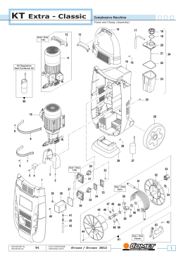
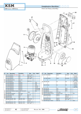
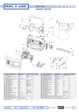
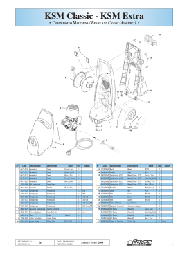
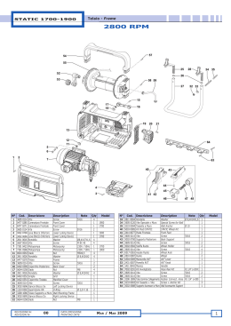
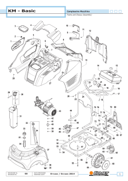
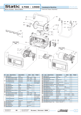
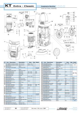
Trapper II
Complessivo Macchina
Frame and Chassy (Assembly)
120 - 130 Gold
9
3
2
1
7
6
5
4

10
60
8
74
62 61
63
64
11
13
73
70 71
65
12
14
72
66
55
69
56
67
15
57
68
16
17
54
22
21
18
20
23
19
49
53
52
24
48
51 50
47
46
25
26
27
28
30
29
31
33
N°
Cod.
Descrizione
1 3208 0895 Tubo
2 1002 0120 Filtro
3 3208 0892 Tubo
4 2803 0408 Raccordo p.g.
REVISIONE Nr.
REVISION Nr.
34
Description
40
41
43
32
Hose
Filter
Hose
Coupling
00
38
39
36
37
42
44
45
35
Note
Q.ty
1
1
Ø6x12 L=90 1
G1/4" PGØ7
1
Ø6x12 L=350
DATA EMISSIONE
PRINTING DATE
Model
N°
Cod.
Descrizione
5 2422 0010 Pompa Gasolio
6 3200 0017 Tappo
7 2803 0486 Raccordo
8 3208 1115 Tubo Gasolio
Aprile / April 2013
Description
Diesel Pump
Plug
Coupling
Diesel Hose
Note
G1/8x8
G1/8"
Ø4
Q.ty
1
1
1
1
Model
1
Trapper II
Complessivo Macchina
Frame and Chassy (Assembly)
120 - 130 Gold
N°
Cod.
8
9
10
11
12
13
14
15
16
17
18
19
20
21
22
23
24
25
26
3208 0998
0402 0396
3625 0028
3625 0037
0218 0012
2807 0011
3607 0106
0402 0397
3044 0021
3208 1098
2822 0018
3206 0320
2811 0002
3607 0195
7301 0607
7301 0606
3002 0699
0466 0050
3632 0089
0404 0037
Descrizione
Description
Copper Diesel Hose
Cover
Screw
Screw
Air Nozzle
Washer
Screw
Exaust Cover
Coil
Suction Hose
Refractary pad
Frame
Washer
Screw
Motorpump
Motorpump
Support
Shraud Cover
Fan
Shraud Cover
0466 0049
0604 0011
3002 0396
1227 0015
0011 0006
Tubo Gasolio Rame
Coperchio
Vite
Vite
Boccaglio
Rondella
Vite
Coperchio Camino
Serpentina
Tubo Aspirazione
Refrattario
Telaio
Rondella
Vite
Motopompa
Motopompa
Supporto
Convogliatore Inferiore
Ventola
Convogliatore
Superiore
Farfalla Aria
Dado
Antivibrante
Ghiera Fiss. Serpentina
Adattatore
27
28
29
30
31
32
33
34
35
36
37
1209 0113
1215 0361
1209 0113
0424 0377
1227 0015
3208 1125
Rondella in Rame
Valvola di Sicurezza
Rondella in Rame
Raccordo Termostato
Ghiera Fiss. Serpentina
Tubo
Copper Washer
Safety Valve
Copper Washer
Thermostata Coupling
Coil-Lock Nut
Hose
Fly Valve
Nut
Silent Block
Coil-Lock Nut
Adapter
39 2000 0041 Nipplo
40 2803 0256 Raccordo
Nipple
Coupling
41 2810 0021 Ruota
Wheel
2

Note
Q.ty
Model
1
1
3,5x25
3
3,5x13
3
1
Ø6,4x11x2
2
M6x10
2
1
1
L=800
1
2
1
Ø10,5x20x2
2
M10x20
2
1 120
1 130
4
1
1
1
Ø4
M6x7,8
M6x33
G3/8"x5
M/F G1/43/8+OGV
G1/4"
G1/4"
G1/4"F
G3/8"x5
R1 G1/4"
L=210 F/F
G3/8"+OGV
G3/8"OGV
M22x1,5
G3/8"F
Ø200x52
1
1
1
1
1
1
1
1
1
1
1
N°
Cod.
Descrizione
Description
42
43
44
45
46
0009 0179
3230 0028
2416 0070
1229 0022
0402 0193
0402 0138
Anello
Termostato
Protezione
Guaina
Copriruota
Copriruota
Ring
Thermostat
Protection
Sheat
Wheel Cover
Wheel Cover
48
47
49
50
51
52
53
54
2811 0097
3607 0097
2803 0408
3623 0031
3201 0029
3606 0199
3226 0082
0477 0281
0477 0291
Rondella
Vite
Raccordo p.g.
Vite
Tappo Livello Olio
Vite
Trasformatore A.T.
Carenatura
Carenatura
Washer
Screw
Straight Hose Tail
Screw
Oil Level Plug
Screw
H.T. Transformer
Cover
Cover
55
56
57
60
61
62
63
64
65
66
67
68
69
70
71
72
73
74
3623 0039
3200 0038
3029 0025
0335 0031
2803 0322
3625 0013
2807 0013
0602 0047
3200 0074
3019 0035
3608 0004
3400 0550
0602 0072
2819 0020
3625 0046
0805 0023
1202 0052
0535 0073
Vite
Tappo Diesel
Serbatoio
Kit Bruciatore
Raccordo
Vite
Rondella Speciale
Disco Porta Elettrodi
Tappo
Seeger Esterno
Vite
Ugello Gasolio
Disco Turbolenza Aria
Rosetta Elastica
Vite
Kit Elettrodo Bifilare
Gancio
Kit Cavi A.T.
Screw
Diesel Plug
Tank Assembly
Burner Kit
Coupling
Screw
Special Washer
Electrode Holder Disc
Plug
Outer Seeger
Screw
Diesel Nozzle
Air Turbolence Ring
Spring Washer
Screw
Bifilar Electrode Kit
Hook
H.T. Cable Kit
Note
Q.ty
2
1
1
Ø6 L=1000
1
Grigio / Grey 2
Azzurro /
2
Cyan
Ø6,5x18x1,5 4
M6x16
4
G1/4" Pg Ø7 1
M5x16
1
G3/4"
1
M5x40
2
230V-50/60HZ 1
Grigio / Grey 1
Azzurro /
1
Cyan
M5x20
1
Nero / Black 1
1
1
Ø4 GC1/8”
1
4,2x9,5
3
4,3x8x1,5
3
1
1
Ø22
1
M3x6
3
0,6 - 45°H
1
1
D.15x5,2x0,4 1
M5x12
1
1
2
L=53
1
Model
Ø20
1
2
REVISIONE Nr.
REVISION Nr.
00
DATA EMISSIONE
PRINTING DATE
Aprile / April 2013
Trapper II
Pompa
Pump
120 - 130 Gold
41
29
33

42
26
3
28
32
2
1
4
81
6
81
100
103
101
5
7
8
26
10
42
9
102
12
11
Solo
Only
130 Gold
104
15
16
32
35
28
33
Solo
Only
120
29
36
37
38
40
44
42
41
27
81
78
52
53
77
76
74
75
50
49
DATA EMISSIONE
PRINTING DATE
55
56
57
73
58
59
60
61
Aprile / April 2013
72
62
63
48
00
82
79
45
51
22
26
80
54
47
21
19
17
25
43
46
24
20
18
23
30
39
REVISIONE Nr.
REVISION Nr.
14
13
31
34
26
64
65
66
67
71
68
70
69
3
Trapper II
Pompa
Pump
120 - 130 Gold
N°
Cod.
Descrizione
Description
1
2
3
4
5
6
7
8
9
10
11
12
13
14
15
16
17
18
19
20
21
22
23
24
25
26
27
28
29
30
31
32
33
34
35
36
37
38
39
40
41
3609 0034
3632 0089
0019 0119
3041 0198
0438 0090
1241 0420
0001 0674
1201 0151
1009 0201
0019 0118
3609 0114
0604 0095
1802 0224
0434 0047
3609 0193
0438 0091
0001 0505
0436 0032
1210 0600
0009 0317
1802 0213
2409 0196
2432 0029
2432 0026
0019 0111
0009 0270
1241 0033
1220 0057
1220 0056
1210 0465
3202 0279
1220 0054
1220 0055
2421 0038
1209 0113
1211 0044
2803 0325
1002 0132
2803 0487
1209 0111
2000 0056
Vite
Ventola Motore
Anello
Kit Statore
Cuscinetto a Sfere
Guarnizione OR
Albero Rotore
Guarnizione
Flangia Motore
Anello Tenuta
Vite
Dado
Fisssagio Condensatore
Condensatore
Vite
Cuscinetto a Sfere
Albero Eccentrico
Cuscinetto
Guarnizione OR
Anello porta Molla
Molla
Pistone
Carter Pompa
Kit Carter Pompa
Anello Tenuta Olio
Anello Portaguarniz.
Guarnizione Tenuta
Gruppo Valv. Mand.
Gruppo Valv. Mand.
Guarnizione OR
Tappo Valvola
Gruppo Valv. Mand.
Gruppo Valv. Mand.
Pressostato
Rondella
Raccordo Curvo
Raccordo Aspirazione
Filtro Aspirazione
Raccordo Ingresso
Guarnizione
Nipplo
Screw
Motor Fan
Ring
Stator Kit
Ball Bearing
O-Ring
Rotor Shaft
Gasket
Motor Flange
Seal
Screw
Nut
Condenser Holder
condenser
Screw
Ball Bearing
Eccentric Shaft
Bearing
O-Ring
Piston Ring
Spring
Piston
Pump Crankcase
Pump Crankcase Kit
Oil Seal
Packing Retainer
Packing
Del. Valve Ass.y kit
Del. Valve Ass.y kit
O-Ring
Valve Cap
Del. Valve Ass.y kit
Del. Valve Ass.y kit
Pressure Switch
Washer
Elbow Coupling
Suction Coupling
Suction Filter
Inlet Coupling
Seal
Nipple
42 3218 0407
3218 0389
43 3609 0065
3609 0191
44 2434 0048
45 0456 0322
46 0402 0276
47 3609 0198
48 3005 0097
49 0009 0229
50 2416 0112
51 1825 0016
52 1210 0550
53 0402 0290
54 3021 0032
55 3009 0141
56 3003 0035
57 1210 0152
58 3009 0148
Testata Pompa
Testata Pompa
Vite
Vite
Pressacavo
Cavo Total Stop
Coperchio TS
Vite
Spina
Anello
Protezione
Interruttore Total-Stop
Guarnizione OR
Scatola TS
Spina Elastica
Sede Easy-Start
Sfera Easy-Start
Guarnizione OR
Sede
Pump Manifold
Pump Manifold
Screw
Screw
Cable Holder
Total Stop Cable
TS Cover
Screw
Pin
Ring
Protection
Total-Stop Switch
O-Ring
TS El. Box
Elastic Pin
Easy-Start Seat
Easy-Start Ball
O-Ring
Seat
4

Note
Q.ty
Model
1
1
1
1
Ø20x47x14
1
Ø1,78x11,11 1
1
1
1
Ø17x30x7
1
M6x30
3
M8
1
1
35µf
1
M6x10
1
Ø17x47x14
1
7°
1
Ø40x60x14
1
Ø3x74
1
3
3
Ø14
3
1
1
Ø14x22,2x5/7 3
3
Ø14x22x6
3
2
1 120
Ø1,78x8,73
3
3
2 130
1
G1/4"
1
G1/4"
1
1
1
1
1
Ø14,5x24,5x3,5 1
M-M
1
130
G3/8-G1/2"
1 120
1 130
M8x65
3 120
M8x60
3 130
1
1
1
M5x20
2
3,5x19,8
1
1
1
16 A
1
Ø1,5x57
1
1
Ø6x22
3
1
1
Ø1,78x9,25
1
1
M6x18
REVISIONE Nr.
REVISION Nr.
N°
Cod.
59
60
61
62
63
64
65
66
67
68
69
0009 0112
1210 0041
0015 0194
1210 0055
0009 0110
1210 0049
1210 0390
3605 0115
1802 0249
1600 0090
3202 0241
70
71
72
73
74
75
76
77
78
79
80
81
82
0604 0087
3622 0047
0432 0044
3021 0035
1215 0339
3202 0280
1802 0177
3600 0087
1210 0220
5027 0025
1210 0465
1220 0054
3601 0114
Descrizione
Description
Anello
Guarnizione OR
Kit Easy Start
Guarnizione OR
Anello
Guarnizione OR
Guarnizione OR
Vite Speciale
Molla Valvola Regolaz.
Kit Leva Total-Stop
Vite Speciale Total-Stop
Ring
O-Ring
Easy Start Kit
O-Ring
Ring
O-Ring
O-Ring
Special Screw
Unloader Valve Spring
Total-Stop Lever Kit
Total-Stop Special
Screw
Dado
Nut
Vite Total-Stop
Total-Stop Adjust. Nut
Cappuccio Total-Stop Total-Stop Cap
Spina Elastica
Elastic Pin
Kit Valvola Regolaz.
Unloader Valve Kit
Tappo
Plug
Molla
Spring
Valvola Non Ritorno
Check Valve
Guarnizione OR
O-Ring
Kit Valvola Non Ritorno Check valve kit
Guarnizione OR
O-Ring
Gruppo Valv. Aspir.
Suct. Valve Ass.y kit
Vite
Screw
Note
Q.ty
1
1
1
Ø1,78x6,07
1
Ø9x6x1,3
1
Ø1,78x12,42 1
Ø2x17
1
1
1
1
Model
Ø12x9x1,3
Ø1,78x8,73
M5
M4x20
Ø2x8
Ø2x4
Ø1,78x8,73
M6x30
1
1
1
1
1
1
1
1
1
1
3
3
3
Kit Ricambi
Spare Parts Kit
100 5026 0257 Kit Valvola Aspir./
Mandata
101 5026 0263 Kit Valvola Aspir./
Mandata
102 5026 0265 Kit Guarnizioni Acqua
103 3300 0085 Kit Testata Completo
104 3300 0093 Kit Testata Completo
00
Suction/Delivery Kit
1 130
Suction/Delivery Kit
1 120
Water Seal Kit
Complete Manifold Kit
Complete Manifold Kit
1
1 120
1 130
DATA EMISSIONE
PRINTING DATE
Aprile / April 2013
Trapper II
Quadro Elettrico
Electric Panel
120 - 130 Gold
1

2
7
8
6
5
3
4
12
11
13
16
SCHEMA ELETTRICO
WIRING DIAGRAM
M
3~
2
1
4
3
6
5
14
R
S
T
Blu (Bleu)
P
13
K
Rosso
PT
(Red)
(Brown)
R
P
t
RIF.
DENOMINAZIONE
(Red)
K1
A2
PV
I
(Brown)
4
5
1
2
10
DESCRIPTION
M
Motore pompa
Pump motor
K
K1
I
R
PT
PV
Termica motore
Teleruttore
Bobina teleruttore
Interruttore 0-1
Rele' stop totale
Pressostato testata
Pressostato valvola
Motor thermic device
Remote control switch
Remote control switch coil
Switch 0-1
Automatic delayed stop relay
Head pressure switch
Valve pressure switch
t
Blu (Bleu)
Marrone
Rosso
A1
14
15
Marrone
ATTENZIONE:
P=
Pressione ( Pressure.)
WARNING:
Le riparazioni devono
essere eseguite SOLO da
personale qualificato !!
Repairs by qualified
personnel only !!
9
COLLEGAMENTO
CONNECTION DIAGRAM
Motore
Motor
U
V
W
Teleruttore
Remote control switch
2
4
A1
5 13
6 14
Rele' stop
totale
3
Motore
Motor
1
Termica motore
Overload motor
A2
Automatic delayed stop relay
U
V
Pressostato valvola
Valve pressure switch
W
1
4
2
5
Pressostato
testata
Head pressure
switch
Interruttore 0-1
Switch 0-1
T S R
N°
Cod.
1
2
3
4
5
6
7
8
9
10
1817 0057
0402 0383
0204 0041
3623 0007
1410 0112
3001 0544
3607 0150
3625 0090
2434 0015
2434 0063
Descrizione
Description
Manopola Termostato
Coperchio
Boccola
Vite
Interruttore
Scatola Elettrica
Vite
Vite
Passacavo
Pressacavo
Thermostat Knob
Cover
Bushing
Screw
Switch
Electrical Box
Screw
Screw
Holder
Cable Holder
REVISIONE Nr.
REVISION Nr.
00
Note
M4x10
M5x25
M5x16
DATA EMISSIONE
PRINTING DATE
Q.ty
1
1
1
2
1
1
1
2
7
1
Model
N°
Cod.
Descrizione
Description
11 2819 0024 Rondella
Washer
12 0604 0061 Dado
Nut
13 0456 0318 Cavo Elettrico + Spina Electrical Cable whit
Plug
14 0456 0361 Cavo Trasformatore
H.T. Transformer Cable
A.T.
15 1610 1201 Schema Elettrico
Electrical Diagram
16 3043 0037 Ritardatore Bruciatore Burner Delayer
Aprile / April 2013
Note
Q.ty
2
M5x5
3
230V L=5500 1
1mm²
L=800
1
Model
1
1
5
Trapper II
Dotazione Standard
Standard Equipment
120 - 130 Gold
1

2
3
6
5
4
N°
Cod.
Descrizione
Description
1 3400 0546 Ugello Acqua
Water Nozzle
2
3301 1143 Lancia
Bent Lance
3
2410 0146 Pistola
Spray Gun
4 3301 0795 Lancia Aspir. Deterg.
6
Lance Foam Kit
Note
(Blister
COMET)
(Blister
COMET)
(Blister
COMET)
(Blister
COMET)
Q.ty
1
Model
1
N°
Cod.
Descrizione
5 0455 0013 Spillo Pulizia Ugello
6 3208 1015 Tubo A.P.
Description
Nozzle Cleaning Pin
H.P. Hose
1
Note
R1 1/4" 8m (Blister
COMET)
Q.ty
1
1
Model
1
REVISIONE Nr.
REVISION Nr.
00
DATA EMISSIONE
PRINTING DATE
Aprile / April 2013
Scaricare