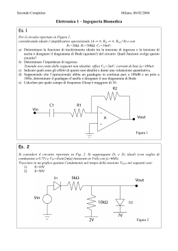
Esercizio no 2 • Si realizzino i seguenti montaggi basati sull’amplificatore operazione 741 e se ne descriva il funzionamento: – amplificatore – amplificatore invertente – integratore o derivatore • Si caratterizzino in modo quantitativo gli ampificatori al variare della frequenza del segnale in ingresso • Si verifichi la banda passante di uno dei due amplificatori al variare del guadagno UCSD: Physics 121; 2012 Inverting amplifier example R2 R1 Vin + Vout • Applying the rules: terminal at “virtual ground” – so current through R1 is If = Vin/R1 • Current does not flow into op-amp (one of our rules) – so the current through R1 must go through R2 – voltage drop across R2 is then IfR2 = Vin(R2/R1) • So Vout = 0 Vin(R2/R1) = Vin(R2/R1) • Thus we amplify Vin by factor R2/R1 – negative sign earns title “inverting” amplifier • Current is drawn into op-amp output terminal Winter 2012 2 UCSD: Physics 121; 2012 Non-inverting Amplifier R2 R1 Vin + Vout • Now neg. terminal held at Vin – so current through R1 is If = Vin/R1 (to left, into ground) • This current cannot come from op-amp input – – – – – so comes through R2 (delivered from op-amp output) voltage drop across R2 is IfR2 = Vin(R2/R1) so that output is higher than neg. input terminal by Vin(R2/R1) Vout = Vin + Vin(R2/R1) = Vin(1 + R2/R1) thus gain is (1 + R2/R1), and is positive • Current is sourced from op-amp output in this example Winter 2012 3 v v+ i v- R + v R a vi v+ v- Rf Ra )vi Rf Voltage follower Ref:080114HKN R2 + v- vo vo Rf Ra + vo vi R1 o f Noninverting amplifier vo (1 v+ vi Noninverting input with voltage divider Rf R2 vo (1 )( )vi Ra R1 R2 vi v+ R1 R2 v- + vo Rf Less than unity gain R2 vo vi R1 R2 Operational Amplifier 4 UCSD: Physics 121; 2012 Summing Amplifier Rf R1 V1 R2 V2 + Vout • Much like the inverting amplifier, but with two input voltages – inverting input still held at virtual ground – I1 and I2 are added together to run through Rf – so we get the (inverted) sum: Vout = Rf(V1/R1 + V2/R2) • if R2 = R1, we get a sum proportional to (V1 + V2) • Can have any number of summing inputs – we’ll make our D/A converter this way Winter 2012 5 UCSD: Physics 121; 2012 Differencing Amplifier R2 R1 V + V+ Vout R1 R2 • The non-inverting input is a simple voltage divider: – Vnode = V+R2/(R1 + R2) • So If = (V Vnode)/R1 – Vout = Vnode IfR2 = V+(1 + R2/R1)(R2/(R1 + R2)) V(R2/R1) – so Vout = (R2/R1)(V V) Winter 2012 6 Differentiator (high-pass) C Vin R Vout 7 UCSD: Physics 121; 2012 Differentiator (high-pass) R C Vin + Vout • For a capacitor • So we have a differentiator, or high-pass filter Winter 2012 8 UCSD: Physics 121; 2012 Low-pass filter (integrator) C R Vin + Vout • If = Vin/R, so C·dVcap/dt = Vin/R – and since left side of capacitor is at virtual ground: – and therefore we have an integrator (low pass) Winter 2012 9
Scaricare