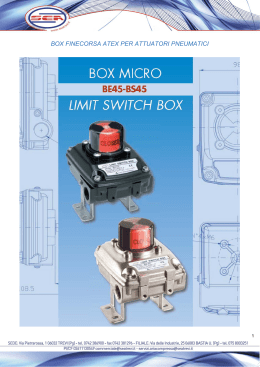
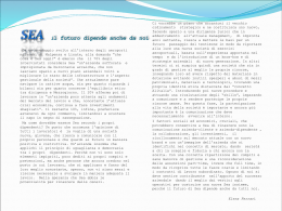
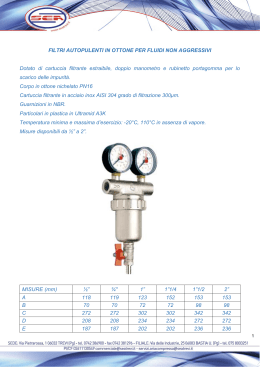
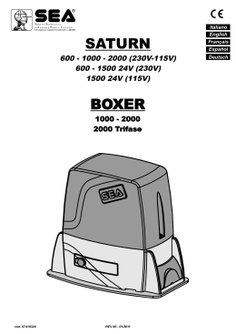
®
Sistemi Elettronici
Italiano
English
di Apertura Porte e Cancelli
International registered trademark n. 804888
SATURN
BOXER
600 - 1000 - 2000 (230V-115V)
600 24V - 1400 24V (230V)
1400 24V (115V)
500 FAST 24V (230V)
1000 - 2000
2000 Threephase
MOTORIDUTTORI PER CANCELLI SCORREVOLI
MOTOR REDUCERS FOR SLIDING GATES
cod. 67410324
REV 06 - 12/2014
®
SATURN - BOXER
Sistemi Elettronici
di Apertura Porte e Cancelli
International registered trademark n. 804888
MOUNTING AND CONNECTING INSTRUCTIONS
The SATURN and the BOXER are motor reducers designed for
the automation of sliding gates with grease lubrication or in oil
bath, depending on the versions.
The irreversibility of the motor reducers allows a perfect and safe
gate closing, and makes the installation of an elecric lock
unneccessary. In case of electric power cut, the lock device
placed on the front part of the motor reducer allows the manual
opening and closing. The operators are equipped with an
electronic clutch device and adjustable mechanical clutch (if
present), which provides an adjustment of the thrust on the
gate, furthermore the electronic inversion system (optional)
through encoder makes out of the Saturn and Boxer motor
reducers a safe and reliable operators allowing in a simple way
to respect the laws in force in the country where the product will
be installed.
MAIN PARTS DENOMINATION
1
2
3
4
5
6
Adjustable foundation plate
Anchor bolts
Pinion protection
Adjusting screws cover
Pinion
Reducer release lever
7 Screw for mechanical clutch adjustment
(Where present)
8 Electronic unit
9 Magnetic encoder (Where present)
ENGLISH
SATURN 600-1000-2000 (115V)
TECHNICAL DATA
Power supply
Power
Absorbed current
Motor capacitor
Working frequency
Working Temperature
Thermoprotection
Weight
Anticrushing clutch
Protection degree
Pinion Z16 (Z20) speed
Maximum torque
Gate maximum weight
Gate maximum length
Mechanical clutch
Limit switch
2000
1000
115 V (±5%) 50/60 Hz
400W
500W
3,2 A
5,0 A
50 µf
70µf
20%
25%
40%
-20°C +55°C
150°C
12 kg
13 kg
14,5 kg
Electronic
Electr./Mech.
IP55
0,15 (0,18)m/s
50 Nm
55Nm
70Nm
600 kg
1000kg
2000kg
6m
10 m
No
Yes
Inductive or mechanical
600
9
SATURN 500 FAST 24V - 600 24V (230V) - 1400 24V (230V)-(115V)
7
8
6
5
4
Gate maximum
length
Limit switch
3
1
2
TECHNICAL DATA 500 FAST (24V) 600 24V (230V) 1400 24V (230V) 1400 24V (115V)
115V~ 50/60 Hz
230V~ 50/60 Hz
Power supply
24V
Motor
100W
65W
100W
Absorbed power
60%
Working frequency
-20°C +55°C
Working Temperature
14,3 kg
Weight
Anticrushing
Eletctronic
clutch
Ip55
Protection degree
0,42 m/s Max
Pinion Z16 (Z20)
0,18 (0,24) m/s Regolabile
(Z20)
speed
0 - 45 Nm
0 - 50 Nm
0 - 60 Nm
Maximum torque
500 kg
600 kg
1400 kg
Gate max. weight
Example: Saturn.
2000
1000
230 V~ 50/60 Hz
330W
550W
750W
1,6 A
2,6 A
3,0 A
10 mF
12,5 mF
12,5 mF
35%
35%
30%
-20°C +55°C
150°C
12 kg
13 kg
14,5 kg
Electronic
Electronic/Mechanical
Ip55
0,15 (0,18) m/s
30 Nm
55 Nm
70 Nm
600 kg
1000 kg
2000 kg
6m
10 m
No
Yes
Yes
Inductive or mechanical
600
Only the OIL version has a clutch
cod. 67410324
Inductive/mechanical
BOXER 1000-2000-2000 Threephase
SATURN 600-1000-2000 (230V)
TECHNICAL DATA
Power supply
Power
Absorbed current
Motor capacitor
Working frequency
Working Temperature
Thermoprotection
Weight
Anticrushing clutch
Protection degree
Pinion Z16 (Z20) speed
Maximum torque
Gate maximum weight
Gate maximum length
Mechanical clutch
Limit switch
10 m
TECHNICAL DATA
Power supply
Power
Absorbed current
Motor capacitor
Working frequency
Working Temperature
Thermoprotection
Weight
Anticrushing clutch
Protection degree
Pinion Z16 (Z20) speed
Maximum torque
Gate maximum weight
Gate maximum length
Mechanical clutch
Limit switch
2000
2000 THREEPHASE
1000
230V (±5%) 50/60Hz 230V/380V(±5%) 50/60Hz
550W
750W
400W
2,6 A
3,0 A
1,0 A
10 µf
12,5 µf
55%
-20°C +55°C
150°C
14 kg
15 kg
Electronic/Mechanical
Mechanical
IP55
0,15 (0,18) m/s
55 Nm
70 Nm
1000 kg
2000 kg
10 m
Yes
Inductive or mechanical
Note: The frequency of use is valid only for the first hour at 20°C
room temperature.
REV 06 - 12/2014
9
®
Sistemi Elettronici
di Apertura Porte e Cancelli
International registered trademark n. 804888
ENGLISH
SATURN - BOXER MOTOR REDUCERS USING GRAPHIC
2. FOUNDATION PLATE ANCHORAGE
To install the foundation plate it is necessary to:
BOXER 2000 - 2000 Threephase
BOXER 1000
S. 1400 24V (230V) (115V)
SATURN 2000 (115V)
SATURN 2000 (115V)
S.600 24V(230V)
SATURN 2000 (230V)
SATURN 2000 (230V)
SATURN 1000 (115V)
SATURN 1000 (230V)
600 kg
S. 600 (115V)
1000 kg
S. 600 (230V)
1400 kg
Gate maximum weight
2000 kg
2.1. Prepare a concret basement with the dimensions shown in
Fig. 1 where the foundation plate and the anchor bolts will be
concreted.
NOTE: It is recommended, gate structure permitting, to lift the
foundation plate about 50mm from the ground, in order to avoid
eventual water stagnation.
Plinto
BOXER 1000
150
35%
BOXER 2000 - 2000 Threephase
30%
SATURN 1400 24V (230V) (115V)
SATURN 600 24V (230V)
SATURN 1000 (115V)
SATURN 1000 (230V)
S. 600 (115V)
SATURN 600 (230V)
25%
65
20%
Use frequency
Motor reducers
40%
25
0
42 0
55%
60%
DIMENSIONS (mm)
Fig. 1
2.2. Before cementing the plate insert a flexible plastic duct of at
least 30mm in diameter into the special hole of the plate.
DIMENSIONS (mm)
2.3. Before concreting in the plate, make sure that it is perfelcty
leveled and that the distance of 58-67 mm as shown in Fig. 2 is
respected.
320
MINIMUN DIMENSION Q
Z16
Z20
21
5
108 mm
116 mm
43-58
345
1. GATE ARRANGEMENT
Before starting with the installation check if all the gate parts
(fixed and mobile) have a strong and as less as possible
deformable structure, also make sure that :
a) The leaf is rigid and compact;
b) The inferior slideway is perfectly straight, horizontal and
without any obstacles which could obstruct the gate sliding;
c) The inferior sliding wheels are equipped with greasable or
water tightened bearings;
d) The superior slideway has been produced and placed so that
the gate is in a perfect vertical position;
e) Mechanical stops of the leaf are always installed in order to
avoid possible derailment of it.
10
cod. 67410324
58-67
Fig. 2
3. CABLES PASSAGE ARRANGEMENT
Saturn and Boxer are provided with two different holes for
electric cables passage.
It’s very important to make the low - tension 230V~ cables pass
through one hole and and the very low safety tension cables
24V through the other one (Fig. 3)
REV 06 - 12/2014
®
Sistemi Elettronici
di Apertura Porte e Cancelli
International registered trademark n. 804888
ENGLISH
5. GEAR RACK MOUNTING
Fig. 3
5.1. Release the motor and open the leaf completely;
Hole 1
5.2. Fix on each gear rack element the support pawls with the
appropriate lock screws, make sure to put them in the upper part
of the hole (Fig. 6) ;
Hole 2
4. FITTING OF THE MOTOR REDUCER
Fig. 6
4.1. Insert the 4 grains into the special holes, so that it is possible to
adjust the motor reducer height on the plate (Fig. 4).
At the end of installation check if the 4 crub screws are well
gripped on the foundation plate.
4.2. Fix the motor reducer to the foundation plate with the 2 included
nuts, adjusting the side position (Fig. 5) so to respect the shown quota
in (Fig. 2).
4.3. Remove the closing loading oil cap (red) and substitute it with
that supplied apart provided with the airhole (black).
5.3. Lean the gear rack element on the toothed pinion of the
motor in parallel to the ground slideway of the gate, as shown in
Fig. 7 and electrically weld the central pawl B to the gate
structure (Fig. 8).
Manually move the gate until pawl C is placed corresponding to
the pinion and fix it through electric welding. Repeat the same
procedure for pawl A after having placed it corresponding to the
pinion;
A
B
C
Fig. 7
Fig. 4
Fig. 8
5.4. Make sure that all the gear rack elements are perfectly
aligned and placed correctly (teeth in phase). It’s suggested to
place two aligned elements in front of a third one as shown in
Fig.9;
5.5. Repeat the above described operation for all the remaining
gear rack elements which have to be installed;
5.6. To avoid that the door weights down on the pinion (Fig.10)
lift up the whole rack about 1,5 mm.
Warning: Keep a gap of about 0,5 mm between pinion tooth
and gear rack tooth;
Fig. 5
cod. 67410324
5.7. Make sure that the gear rack works at the center of the
pinion along all rack elements, if necessary, adjust the length of
the spacers.
REV 06 - 12/2014
11
®
Sistemi Elettronici
di Apertura Porte e Cancelli
International registered trademark n. 804888
ENGLISH
Inductive limit switch
Fig. 9
1,5 mm
Fig. 13
Position in which must be the
spring (mechanical limit switch) or
the pointer (inductive limit switch)
Fig. 10
6. LIMIT SWITCH ADJUSTMENT
Fig. 14
50 mm
X
6.1. In order to install and adjust the limit switch in opening, follow
the below mentioned instructions (Fig. 11):
- Take the gate to complete opening,
- Place the small plate on the gear rack so that the limit switch is
(small lever in case of mechanical limit switch (Fig. 12); small
pointers placed on the upper part in case of inductive limit switch
(Fig. 13)) in corrispondence of pointX which is placed 50 mm
from the folded side of the small plate (Fig. 14) and fix it with the
delivered screws (Fig. 15 - Fig.16).
6.2. In order to install and adjust the limit switch in closing, follow
the below mentioned instructions (Fig. 11):
- Take the gate to complete closing
- Place the small plate on the gear rack so that the limit switch is
in corrispondence of pointX which is placed 50 mm from the
folded side of the small plate (Fig. 14) and fix it with the delivered
screws (Fig. 15 - Fig.16).
Limit switch in closing
Fig. 11
Limit switch in opening
Fig. 15
Mechanical limit switch
Fig. 16
Fig. 12
12
cod. 67410324
Adjusting the trimmer for braking, placed on the electronic
control unit, it is possible to make the gate stop on the desired
position.
REV 06 - 12/2014
®
Sistemi Elettronici
di Apertura Porte e Cancelli
International registered trademark n. 804888
ENGLISH
7. MAGNETIC LIMIT SWITCH
8. GROUNDING (Fig. 21 - Fig. 22)
Example: Boxer
Fig.17
Fig. 21
Example: Saturn 24V
Steel rack
N
Fig.18
F
Plastic rack
Fig. 22
Fig.19
9. CLUTCH ADJUSTMENT (Where present)
Sliding gate
MAX 10 mm
Magnet
Limit sheet
Rack
Pinion
9.1. Switch off electric power.
9.2. In order to adjust the clutch it is necessary to:
- Act on the scrub screw “A” (Fig. 23) as follows:
- Turning clockwise = less clutch sensibility / more thrust force
-Counter clockwise = more clutch sensibility / less thrust force
+ power
- sensibility
Ex. Boxer
A
- power
+ sensibility
Fig.20
Fig. 23
cod. 67410324
REV 06 - 12/2014
13
®
Sistemi Elettronici
di Apertura Porte e Cancelli
International registered trademark n. 804888
ENGLISH
10. SCREW COVER MOUNTING
12. RISK EXAMINATION
At the end of the mechanical installation and after having
executed all the required adjustments, mount the two screw
covers on the operator as shown in Fig. 24.
The points pointed by arrows in Fig. 26 are potentially
dangerous. The installer must take a thorough risk examination
to prevent crushing, conveying, cutting, grappling, trapping so
as to guarantee a safe installation for people, things and animals
(Re. Laws in force in the country where the installation has been
made.)
Fig. 26
Fig. 24
13. NOTICE
11. ELECTRIC CONNECTIONS OF THE
INSTALLATION (Fig. 25)
Fig. 25
The cable mesures are indicated in mm2
8
6
7
1
3x1
4
5
2
2x1
2x1
,5
8x1
6x1
,5
,5
,5
3 x1
9
1 x1
,5
3
2x1
,5
,5
,5
10
3 x1
1) Saturn - Boxer
2) Photocell Sx
3) Photocell Dx
4) Mechanical safety edge
5) Key push botton
SEA can not be deemed responsible for any damage or accident
caused by product breaking, being damages or accidents due to
a failure to comply with the instructions herein. The guarantee
will be void and the manufacturer responsibility (according to
Machine Law) will be nullified if SEA original spare parts are not
being used.
The electrical installation shall be carried out by a professional
technician who will release documentation as requested by the
laws in force. This is a quotation from the GENERAL
DIRECTIONS that the installer must read carefully before
installing. Packaging materials such as plastic bags, foam
polystyrene, nails etc must be kept out of children’s reach as
dangers may arise.
,5
6) Flasher
7) Receiver
8) Warning notice
9) Junction box
10) Differential 16A - 30mA
14. SAFETY PRECAUTIONS:
All electrical work and the choice of the operating logic should
conform to current regulations. A 16 A 0,030 A differential
switch must be incorporated into the source of the operators
main electrical supply and the entire system properly earth
bonded. Always run mains carrying cables in separate ducts to
low voltage control cables to prevent mains interference.
15. SPARE PARTS:
To obtain spare parts contact:
SEA S.p.A. -Zona Ind.le, 64020 S. ATTO Teramo Italia
Ex. 230V version with integrated electronic control unit
14
cod. 67410324
REV 06 - 12/2014
®
Sistemi Elettronici
di Apertura Porte e Cancelli
International registered trademark n. 804888
ENGLISH
1 6 . S A F E T Y A N D E N V I R O N M E N TA L
COMPATIBILITY:
Don’t waste product packing materials and/or circuits.
When being transported this product must be properly
packaged and handled with care.
SEA reserves the right to do changes or variations that may be
necessary to its products with no obligation to notice.
17. PERIODIC MAINTENANCE
Check the oil level (where present)
(Use the oil level rod)
Annual
Change oil
4 years
Check the release functionality
Check the clutch functionality
(where present)
Annual
18.1. In order to release do as follows:
-Open the lock cover, insert the key and rotate it 90° clockwise
(Fig. 27).
- Pull the release lever until it stops, about 90° approximately
(Fig. 28).
Note: when you pull the release lever, the electronic control
unit receives a stop impulse thanks to a micro-switch
placed inside.
18.2. In order to relock do as follows:
- Push the release lever to complete closing.
- Rotate the key counter-clockwise and extract it.
- Close the protective lock cover.
Once the lock has been restored the electronic control unit
reactivates
Close
Annual
Check the usury status of pinion and
gear rack
Annual
Check the fixing screws
Annual
Check limit switch functionality and status in
opening and closing and the related
small plates
18. RELEASE SYSTEM FOR SATURN AND
BOXER
Annual
Check the distance between pinion and gear
rack (1.5 mm)
Check the connection cables integrity
Page for both instaler and user
Open
Fig. 27
Annual
Annual
All the above described operations must be done exclusively by
an authorized installer.
Fig. 28
cod. 67410324
REV 06 - 12/2014
15
®
Sistemi Elettronici
di Apertura Porte e Cancelli
International registered trademark n. 804888
TERMS OF SALES
EFFICACY OF THE FOLLOWING TERMS OF SALE: the following general terms of sale shall be applied to all orders sent to SEA
S.p.A. All sales made by SEA to all costumers are made under the prescription of this terms of sales which are integral part of sale
contract and cancel and substitute all apposed clauses or specific negotiations present in order document received from the buyer.
GENERAL NOTICE The systems must be assembled exclusively with SEA components, unless specific agreements apply. Noncompliance with the applicable safety standards (European Standards EM12453 – EM 12445) and with good installation practice
releases SEA from any responsibilities. SEA shall not be held responsible for any failure to execute a correct and safe installation under
the above mentioned standards.
1) PROPOSED ORDER The proposed order shall be accepted only prior SEA approval of it. By signing the proposed order, the Buyer
shall be bound to enter a purchase agreement, according to the specifications stated in the proposed order.
On the other hand, failure to notify the Buyer of said approval must not be construed as automatic acceptance on the part of SEA.
2) PERIOD OF THE OFFER The offer proposed by SEA or by its branch sales department shall be valid for 30 solar days, unless
otherwise notified.
3) PRICING The prices in the proposed order are quoted from the Price List which is valid on the date the order was issued. The
discounts granted by the branch sales department of SEA shall apply only prior to acceptance on the part of SEA. The prices are for
merchandise delivered ex-works from the SEA establishment in Teramo, not including VAT and special packaging. SEA reserves the
right to change at any time this price list, providing timely notice to the sales network. The special sales conditions with extra discount
on quantity basis (Qx, Qx1, Qx2, Qx3 formula) is reserved to official distributors under SEA management written agreement.
4) PAYMENTS The accepted forms of payment are each time notified or approved by SEA. The interest rate on delay in payment shall
be 1.5% every month but anyway shall not be higher than the max. interest rate legally permitted.
5) DELIVERY Delivery shall take place, approximately and not peremptorily, within 30 working days from the date of receipt of the
order, unless otherwise notified. Transport of the goods sold shall be at Buyer’s cost and risk. SEA shall not bear the costs of delivery
giving the goods to the carrier, as chosen either by SEA or by the Buyer. Any loss and/or damage of the goods during transport, are at
Buyer’s cost.
6) COMPLAINTS Any complaints and/or claims shall be sent to SEA within 8 solar days from receipt of the goods, proved by adequate
supporting documents as to their truthfulness.
7) SUPPLY The concerning order will be accepted by SEA without any engagement and subordinately to the possibility to get it’s
supplies of raw material which is necessary for the production; Eventual completely or partially unsuccessful executions cannot be
reason for complains or reservations for damage. SEA supply is strictly limited to the goods of its manufacturing, not including
assembly, installation and testing. SEA, therefore, disclaims any responsibility for damage deriving, also to third parties, from noncompliance of safety standards and good practice during installation and use of the purchased products.
8) WARRANTY The standard warranty period is 12 months. This warranty time can be extended by means of expedition of the
warranty coupon as follows:
SILVER: The mechanical components of the operators belonging to this line are guaranteed for 24 months from the date of
manufacturing written on the operator.
GOLD: The mechanical components of the operators belonging to this line are guaranteed for 36 months from the date of
manufacturing written on the operator.
PLATINUM: The mechanical components of the operators belonging to this line are guaranteed for 36 months from the date of
manufacturing written on the operator. The base warranty (36 months) will be extended for further 24 months (up to a total of 60
months) when it is acquired the certificate of warranty which will be filled in and sent to SEA S.p.A. The electronic devices and the
systems of command are guaranteed for 24 months from the date of manufacturing. In case of defective product, SEA undertakes to
replace free of charge or to repair the goods provided that they are returned to SEA repair centre. The definition of warranty status is by
unquestionable assessment of SEA. The replaced parts shall remain propriety of SEA. Binding upon the parties, the material held in
warranty by the Buyer, must be sent back to SEA repair centre with fees prepaid, and shall be dispatched by SEA with carriage forward.
The warranty shall not cover any required labour activities.
The recognized defects, whatever their nature, shall not produce any responsibility and/or damage claim on the part of the Buyer
against SEA. The guarantee is in no case recognized if changes are made to the goods, or in the case of improper use, or in the case of
tampering or improper assembly. Furthermore, the warranty shall not apply if SEA products are partly or completely coupled with nonoriginal mechanical and/or electronic components, and in particular, without a specific relevant authorization, and if the Buyer is not
making regular payments. The warranty shall not cover damage caused by transport, expendable material, faults due to nonconformity with performance specifications of the products shown in the price list. No indemnification is granted during repairing and/or
replacing of the goods in warranty. SEA disclaims any responsibility for damage to objects and persons deriving from non-compliance
with safety standards, installation instructions or use of sold goods.
9) RESERVED DOMAIN A clause of reserved domain applies to the sold goods; SEA shall decide autonomously whether to make use
of it or not, whereby the Buyer purchases propriety of the goods only after full payment of the latter.
10) COMPETENT COURT OF LAW In case of disputes arising from the application of the agreement, the competent court of law is the
tribunal of Teramo. SEA reserves the faculty to make technical changes to improve its own products, which are not in this price list at
any moment and without notice. SEA declines any responsibility due to possible mistakes contained inside the present price list
caused by printing and/or copying. The present price list cancels and substitutes the previous ones. The Buyer, according to the law
No. 196/2003 (privacy code) consents to put his personal data, deriving from the present contract, in SEA archives and electronic files,
and he also gives his consent to their treatment for commercial and administrative purposes. Industrial ownership rights: once the
Buyer has recognized that SEA has the exclusive legal ownership of the registered SEA brand, he will commit himself to use it in a way
which does not reduce the value of these rights, he won’t also remove, replace or modify brands or any other particularity from the
products. Any kind of replication or use of SEA brand is forbidden as well as of any particularity on the products, unless preventive and
expressed authorization by SEA.
In accomplishment with art. 1341 of the Italian Civil Law it will be approved expressively clauses under numbers:
4) PAYMENTS - 8) GUARANTEE - 10) COMPETENT COURT OF LOW
cod. 67410324
REV 06 - 12/2014
17
®
Sistemi Elettronici
di Apertura Porte e Cancelli
International registered trademark n. 804888
Italiano AVVERTENZE GENERALI PER INSTALLATORE E UTENTE
1. Leggere attentamente le Istruzioni di Montaggio e le Avvertenze Generali prima di iniziare l’installazione del prodotto. Conservare la documentazione per
consultazioni future
2. Non disperdere nell’ ambiente i materiali di imballaggio del prodotto e/o circuiti
3. Questo prodotto è stato progettato e costruito esclusivamente per l’utilizzo indicato in questa documentazione. Qualsiasi altro utilizzo non espressamente indicato
potrebbe pregiudicare l’integrità del prodotto e/o rappresentare fonte di pericolo. L’uso improprio è anche causa di cessazione della garanzia. La SEA S.p.A. declina
qualsiasi responsabilità derivata dall’uso improprio o diverso da quello per cui l’automatismo è destinato.
4. I prodotti SEA sono conformi alle Direttive: Macchine (2006/42/CE e successive modifiche), Bassa Tensione (2006/95/CE e successive modifiche), Compatibilità
Elettromagnetica (2004/108/CE e successive modifiche). L’installazione deve essere effettuata nell’osservanza delle norme EN 12453 e EN 12445.
5. Non installare l’apparecchio in atmosfera esplosiva.
6. SEA S.p.A. non è responsabile dell’inosservanza della Buona Tecnica nella costruzione delle chiusure da motorizzare, nonché delle deformazioni che dovessero
verificarsi durante l’ uso.
7. Prima di effettuare qualsiasi intervento sull’impianto, togliere l’alimentazione elettrica e scollegare le batterie. Verificare che l’impianto di terra sia realizzato a
regola d’arte e collegarvi le parti metalliche della chiusura.
8. Per ogni impianto SEA S.p.A. consiglia l’utilizzo di almeno una segnalazione luminosa nonché di un cartello di segnalazione fissato adeguatamente sulla struttura
dell’infisso.
9. SEA S.p.A. declina ogni responsabilità ai fini della sicurezza e del buon funzionamento della automazione, in caso vengano utilizzati componenti di altri produttori.
10. Per la manutenzione utilizzare esclusivamente parti originali SEA.
11. Non eseguire alcuna modifica sui componenti dell’automazione.
12. L’installatore deve fornire tutte le informazioni relative al funzionamento manuale del sistema in caso di emergenza e consegnare all’Utente utilizzatore
dell’impianto il libretto d’avvertenze allegato al prodotto.
13. Non permettere ai bambini o persone di sostare nelle vicinanze del prodotto durante il funzionamento. L’applicazione non può essere utilizzata da bambini, da
persone con ridotte capacità fisiche, mentali, sensoriali o da persone prive di esperienza o del necessario addestramento. Tenere inoltre fuori dalla portata dei
bambini radiocomandi o qualsiasi altro datore di impulso, per evitare che l’automazione possa essere azionata involontariamente.
14. Il transito tra le ante deve avvenire solo a cancello completamente aperto.
15. Tutti gli interventi di manutenzione, riparazione o verifiche periodiche devono essere eseguiti da personale professionalmente qualificato. L’utente deve
astenersi da qualsiasi tentativo di riparazione o d’intervento e deve rivolgersi esclusivamente a personale qualificato SEA. L’utente può eseguire solo la manovra
manuale.
2
16. La lunghezza massima dei cavi di alimentazione fra centrale e motori non deve essere superiore a 10 m. Utilizzare cavi con sezione 2.5 mm . Utilizzare cablaggi
con cavi in doppio isolamento (cavi con guaina) nelle immediate vicinanze dei morsetti specie per il cavo di alimentazione (230V). Inoltre è necessario mantenere
adeguatamente lontani (almeno 2.5 mm in aria) i conduttori in bassa tensione (230V) dai conduttori in bassissima tensione di sicurezza (SELV) oppure utilizzare
un’adeguata guaina che fornisca un isolamento supplementare avente uno spessore di almeno 1 mm.
English GENERAL NOTICE FOR THE INSTALLER AND THE USER
1. Read carefully these Instructions before beginning to install the product. Store these instructions for future reference
2. Don’t waste product packaging materials and /or circuits.
3. This product was designed and built strictly for the use indicated in this documentation. Any other use, not expressly indicated here, could compromise the good
condition/operation of the product and/or be a source of danger. SEA S.p.A. declines all liability caused by improper use or different use in respect to the intended
one.
4. The mechanical parts must be comply with Directives: Machine Regulation 2006/42/CE and following adjustments), Low Tension (2006/95/CE), electromgnetic
Consistency (2004/108/CE) Installation must be done respecting Directives: EN12453 and En12445.
5. Do not install the equipment in an explosive atmosphere.
6. SEA S.p.A. is not responsible for failure to observe Good Techniques in the construction of the locking elements to motorize, or for any deformation that may occur
during use.
7. Before attempting any job on the system, cut out electrical power and disconnect the batteries. Be sure that the earthing system is perfectly constructed, and
connect it metal parts of the lock.
8. Use of the indicator-light is recommended for every system, as well as a warning sign well-fixed to the frame structure.
9. SEA S.p.A. declines all liability as concerns the automated system’s security and efficiency, if components used, are not produced by SEA S.p.A..
10. For maintenance, strictly use original parts by SEA.
11. Do not modify in any way the components of the automated system.
12. The installer shall supply all information concerning system’s manual functioning in case of emergency, and shall hand over to the user the warnings handbook
supplied with the product.
13. Do not allow children or adults to stay near the product while it is operating. The application cannot be used by children, by people with reduced physical, mental
or sensorial capacity, or by people without experience or necessary training. Keep remote controls or other pulse generators away from children, to prevent
involuntary activation of the system.
14. Transit through the leaves is allowed only when the gate is fully open.
15. The User must not attempt to repair or to take direct action on the system and must solely contact qualified SEA personnel or SEA service centers. User can apply
only the manual function of emergency.
16. The power cables maximum length between the central engine and motors should not be greater than 10 m. Use cables with 2,5 mm2 section. Use double
insulation cable (cable sheath) to the immediate vicinity of the terminals, in particular for the 230V cable. Keep an adequate distance (at least 2.5 mm in air), between
the conductors in low voltage (230V) and the conductors in low voltage safety (SELV) or use an appropriate sheath that provides extra insulation having a thickness
of 1 mm.
Français CONSIGNES POUR L’INSTALLATEUR ET L’UTILISATEUR
1. Lire attentivement les instructions avant d’installer le produit.Conserver les instructions en cas de besoin.
2. Ne pas dispenser dans l’ environnement le materiel d’ emballage du produit et/ou des circuits
4. Ce produit a été conçu et construit exclusivement pour l’usage indiqué dans cette fiche. Toute autre utilisation non expressément indiquée pourraient
compromettre l’intégrité du produit et/ou représenter une source de danger. SEA S.p.A. décline toute responsabilités qui dériverait d’usage impropre ou différent de
celui auquel l’automatisme est destiné.Une mauvaise utilisation cause la cessation de la garantie.
5. Les composants doivent répondre aux prescriptions des Normes: Machines (2006/42/CE et successifs changements); Basse Tension (2006/95/CE et successifs
changements); EMC (2004/108/CE et successifs changements). L’installation doit être effectuée conformément aux Normes EN 12453 et EN 12445.
6. Ne pas installer l’appareil dans une atmosphère explosive.
7. SEA S.p.A. n’est pas responsable du non-respect de la Bonne Technique de construction des fermetures à motoriser, ni des déformations qui pourraient intervenir
lors de l’utilisation.
8. Couper l’alimentation électrique et déconnecter la batterie avant toute intervention sur l’installation.Vérifier que la mise à terre est réalisée selon les règles de l’art
et y connecter les pièces métalliques de la fermeture.
9. On recommande que toute installation soit doté au moins d’une signalisation lumineuse, d’un panneau de signalisation fixé, de manière appropriée, sur la
structure de la fermeture.
10. SEA S.p.A. décline toute responsabilité quant à la sécurité et au bon fonctionnement de l’automatisme si les composants utilisés dans l’installation
n’appartiennent pas à la production SEA.
18
cod. 67410324
REV 06 - 12/2014
®
Sistemi Elettronici
di Apertura Porte e Cancelli
International registered trademark n. 804888
11. Utiliser exclusivement, pour l’entretien, des pièces SEA originales.
12. Ne jamais modifier les composants d’automatisme.
13. L’installateur doit fournir toutes les informations relatives au fonctionnement manuel du système en cas d’urgence et remettre à l’Usager qui utilise l’installation
les “Instructions pour l’Usager” fournies avec le produit.
14. Interdire aux enfants ou aux tiers de stationner près du produit durant le fonctionnement. Ne pas permettre aux enfants, aux personnes ayant des capacités
physiques, mentales et sensorielles limitées ou dépourvues de l’expérience ou de la formation nécessaires d’utiliser l’application en question. Eloigner de la portée
des enfants les radiocommandes ou tout autre générateur d’impulsions, pour éviter tout actionnement involontaire de l’automatisme.
15. Le transit entre les vantaux ne doit avoir lieu que lorsque le portail est complètement ouvert.
16. L’utilisateur doit s’abstenir de toute tentative de réparation ou d’intervention et doigt s’adresser uniquement et exclusivement au personnel qualifié SEA ou aux
centres d’assistance SEA. L’utilisateur doigt garder la documentation de la réparation. L’utilisateur peut exécuter seulement la manoeuvre manuel.
17. La longueur maximum des câbles d’alimentation entre la carte et les moteurs ne devrait pas être supérieure à 10 m. Utilisez des câbles avec une section de 2,5
2
mm . Utilisez des câblage avec cable à double isolation (avec gaine) jusqu’à proximité immédiate des terminaux, en particulier pour le câble d’alimentation (230V). Il
est également nécessaire de maintenir une distance suffisante (au moins 2,5 mm dans l’air), entre les conducteurs en basse tension (230V) et les conducteurs de
très basse tension de sécurité (SELV) ou utiliser une gaine ayant une épaisseur d’au moin 1 mm, qui fournisse une isolation supplémentaire.
Español ADVERTENCIAS GENERALES PARA INSTALADORES Y USUARIOS
1 Leer las instrucciones de instalación antes de comenzar la instalación. Mantenga las instrucciones para consultas futura
2. No disperdiciar en el ambiente los materiales de embalaje del producto o del circuito
3. Este producto fue diseñado y construido exclusivamente para el uso especificado en esta documentación. Cualquier otro uso no expresamente indicado puede
afectar la integridad del producto y ser una fuente de peligro. El uso inadecuado es también causa de anulación de la garantía. SEA S.p.A. se exime de toda
responsabilidad causadas por uso inapropiado o diferente de aquel para el que el sistema automatizado fue producido.
4. Los productos cumplen con la Directiva: Maquinas (2006/42/CE y siguientes modificaciones), Baja Tension (2006/95/CE, y siguientes modificaciones),
Compatibilidad Electromagnética (2004/108/CE modificada). La instalación debe ser llevada a cabo de conformidad a las normas EN 12453 y EN 12445.
5. No instalar el dispositivo en una atmósfera explosiva.
6. SEA S.p.A. no es responsable del incumplimiento de la mano de obra en la construcción de la cacela a automatizar y tampoco de las deformaciones que puedan
producirse durante el uso.
7. Antes de realizar cualquier operación apagar la fuente de alimentación y desconectar las baterías. Comprobar que el sistema de puesta a tierra sea diseñado de
una manera profesional y conectar las partes metálicas del cierre.
8. Para cada instalación se recomienda utilizar como mínimo una luz parpadeante y una señal de alarma conectada a la estructura del marco.
9. SEA S.p.A. no acepta responsabilidad por la seguridad y el buen funcionamiento de la automatización en caso de utilización de componentes no producidos por
SEA.
10. Para el mantenimiento utilizar únicamente piezas originales SEA S.p.A..
11. No modificar los componentes del sistema automatizado.
12. El instalador debe proporcionar toda la información relativa al funcionamiento manual del sistema en caso de emergencia y darle al usuario el folleto de adjunto
al producto.
13. No permita que niños o adultos permanecen cerca del producto durante la la operación. La aplicación no puede ser utilizada por niños, personas con movilidad
reducida de tipo fìsico, mental, sensorial o igual por personas sin experiencia o formación necesaria. Tener los radiomandos fuera del alcance de niños asì como
cualquier otro generador de impulsos radio para evitar que el automación pueda ser accionada accidentalmente.
14. El tránsito a través de las hojas sólo se permite cuando la puerta está completamente abierta.
15. Todo el mantenimiento, reparación o controles deberán ser realizados por personal cualificado. Evitar cualquier intente a reparar o ajustar. En caso de necesitad
comunicarse con un personal SEA calificado. Sólo se puede realizar la operación manual.
16. La longitud máxima de los cables de alimentación entre motor y central no debe ser superior a 10 metros. Utilizar cables con 2,5 mm2. Utilizar cables con doble
aislamiento (cables con váina) hasta muy cerca de los bornes, especialmente por el cable de alimentación (230V). Además es necesario mantener adecuadamente
distanciados (por lo menos 2,5 mm en aire) los conductores de baja tensión (230V) y los conductores de baja tensión de seguridad (SELV) o utilizar una váina
adecuada que proporcione aislamiento adicional con un espesor mínimo de 1 mm.
Deutsch ALLGEMEINE HINWEISE FUER DEN INSTALLATEUR UND DEN NUTZER
1.Lesen Sie die Installierungsanweisungen sorgfältig durch bevor Sie mit der Installierung beginnen.Diese Anweisungen an einem leicht zugänglichen Ort
aufbewahren.
2.Verpackungsmaterial des Produkts und/oder der Schaltkreise umweltgerecht entsorgen.
3. Dieses Produkt wurde speziell und ausschließlich für den, in den Unterlagen beschriebenen Zweck, geplant und hergestellt. Jede andere Verwendung, die nicht
ausdrücklich angegeben wurde kann die Integrität des Produkts schädigen und/oder eine Gefahrenquelle darstellen. Die nicht fachgerechte Nutzung des Produkts
bewirkt die Erlöschung der Garantie. SEA S.p.A. lehnt jegliche Haftung, für unsachgemäße oder andere Nutzung, als die wofür das Produkt bestimmt ist, ab.
4. SEA Produkte entsprechen den folgenden Richtlinien: Maschinenrichtlinie (2006/42/EG und nachträglich geänderten Fassungen), Niederspannungs-Richtlinie
(2006/95/EG und nachträglich geänderten Fassungen), EMV (2004/108/EG und nachträglich geänderten Fassungen). Installation gemäß Standard EN12453 und
EN12445 durchführen.
5. Installieren Sie das Gerät nicht in explosionsgefährdeten Umgebungen, das Vorhandensein von brennbaren Gasen oder Dämpfen stellt ein ernstes
Sicherheitsrisiko dar.
6. SEA S.p.A. ist nicht für die Nichtbeachtung der Guten Technik bei der Herstellung von zu motorisierenden Toren und für deren eventuellen Verformungen, die
während des Gebrauchs auftreten könnten, haftbar.
7. Vor allen Eingriffen, das Gerät ausschalten und die Batterien trennen. Sicherstellen, dass die Erdung fachgerecht hergestellt wurde und die Metallteile des Tores
daran anschließen.
8. Für jede Anlage wird empfohlen, mindestens ein Blinklicht zu montieren und ein Warnschild auf der Torstruktur anzubringen.
9. SEA S.p.A. übernimmt keine Haftung für Sicherheit und reibungslosen Betrieb des Antriebs, bei Verwendung von Komponenten, die nicht von der SEA Produktion
stammen.
10. Für die Wartung nur SEA Originalteile verwenden.
11. Keinerlei Änderungen auf Komponenten der Automation vornehmen.
12. Der Installateur muss den Nutzer des Antriebs über den manuellen Betrieb des Systems im Notfall unterrichten und ihm, das, dem Produkt beiliegende,
Handbuch übergeben.
13. Der Aufenthalt von Kindern oder Erwachsenen in der Nähe des Tores während seines Betriebes ist nicht gestattet. Die Anlage darf nicht von Kindern,
Personen mit eingeschränkten körperlichen, geistigen oder sensorischen Fähigkeiten oder von Menschen ohne notewendige Erfahrung oder Anweisungen benutzt
werden. Fernbedienungen oder andere Impulsgeber außerhalb der Reichweite von Kindern halten, um die versehentliche Aktivierung der Anlage zu verhindern.
14. Die Durchfahrt zwischen den Flügeln ist nur bei vollständig geöffnetem Tor zulässig.
15. Sämtliche Wartungs-und Reparaturarbeiten oder periodische Kontrollen, müssen von qualifiziertem Fachpersonal durchgeführt werden. Der Endverbraucher
muss davon absehen eigenständig Reparaturen oder Eingriffe jeder Art an der Anlage durzuführen und muss sich aussschliesslich an qualifiziertes SEA
Fachersonal wenden. Der Endverbraucher darf nur die manuelle Notfunktion durchführen.
16. Die maximale Länge der Stromkabel zwischen Steuerung und Motoren ist 10 Meter. Verwenden Sie Kabel mit 2,5 mm2 Querschnitt und Doppelisolierung
(Kabelmantel) in der unmittelbaren Nähe von Klemmen, insbesondere für das Speisungskabel (230V). Die Speisungskabel (230V) und die SicherheitsNiederspannugnskabel (SELV) müssen in einem Abstand von mindestens 2,5 mm gehalten werden, oder eine geeignete Hülse von 1mm Dicke , für eine
zusätzliche Isolierung verwenden..
cod. 67410324
REV 06 - 12/2014
19
®
Sistemi Elettronici
di Apertura Porte e Cancelli
International registered trademark n. 804888
Dichiarazione di conformità
Declaration of Conformity
La SEA S.p.A. dichiara che, con l’installazione degli adeguati dispositivi di sicurezza e di filtraggio
disturbi, i prodotti:
SEA S.p.A. declares that by installing the appropriate safety equipment and noise filtering the products:
Descrizione / Description
Modello / Model
Marca / Trademark
Motoriduttore Saturn 600/1000/2000 (e tutti i suoi derivati)
Motor reducer Saturn 600/1000/2000 (and all its by-products)
12400210/5 - 12400100/5 - 12400040/5
12400210/5 - 12400100/5 - 12400040/5
SEA
SEA
Motoriduttore Saturn 1400 Oil 24V (e tutti i suoi derivati)
Motor reducer Saturn 1400 Oil 24V (and all its by-products)
12400030/3
12400030/3
SEA
SEA
Boxer 600/1000/2000 (e tutti i suoi derivati)
Boxer 600/1000/2000 (and all its by-products)
12405300 -12405000/5 - 12405200/5
12405300 - 12405000/5 - 12405200/5
SEA
SEA
sono costruiti per essere incorporati in una macchina o per essere assemblati con altri macchinari per
costruire una macchina ai sensi della Direttiva 2006/42/CE:
are built to be integrated into a machine or to be assembled with other machinery to create a machine
under the provisions of Directive 2006/42/CE:
sono conformi ai requisiti essenziali di sicurezza relativi ai prodotti entro il campo di applicabilità delle
Direttive Comunitarie 2006/95/CE e 2004/108/CE.
they are conforming to the essential safety requirements related to the products within the field of
applicability of the Community Directives 2006/95/CE and 2004/108/CE.
COSTRUTTORE o RAPPRESENTANTE AUTORIZZATO:
MANUFACTURER or AUTHORISED REPRESENTATIVE:
SEA S.p.A.
DIREZIONE E STABILIMENTO:
Zona industriale 64020 S.ATTO Teramo - (ITALY)
Tel. 0861 588341 r.a. Fax 0861 588344
Http://www.seateam.com
I test sul prodotto sono stati effettuati in configurazione standard e in riferimento alle norme specifiche per
la sua classe d'utilizzo.
The products have been tested in standard configuration and with reference to the special norms
concerning the classe of use.
Luogo, data di emissione
Plase, date of issue
Teramo, 19/05/2014
20
cod. 67410324
L’ Amministratore
The Administrator
Ennio Di Saverio
REV 06 - 12/2014
Questo articolo è stato prodotto seguendo rigide procedure
di lavorazione ed è stato testato singolarmente al fine di
garantire i più alti livelli qualitativi e la vostra soddisfazione.
Vi ringraziamo per aver scelto SEA.
This item has been produced following strict production
procedures and has been singularly tested for the highest
quality levels and for your complete satisfaction.
Thanks for choosing SEA.
Cet article a été produit suivant des procédures d'usinage
strictes et il a singulièrement été testé afin de garantir
les plus hauts niveaux de qualité pour votre satisfaction.
Nous vous remercions d'avoir choisi SEA.
Este articulo ha sido producido siguiendo rigidos
procedimientos de elaboracion y ha sido probando
singolarmente a fin de garantizar los mas altos inveles de
calidad y vuestra satisfaccion.
Le agradecemos por haber escogito SEA.
C
CERTIFICATO DI ESTENSIONE GARANZIA
CERTIFICATE OF WARRANTY EXTENTION
n.
PRODOTTO/ PRODUCT
- Modello/Model____________________________________________________
- Matricola n. /Serial Number_________________________________________
- Data di acquisto/Date of order________________________________________
- Data di installazione/Date of installation_______________________________
Centrale/Control unit
Fotocellule/Photocells
RX - TX
Altri accessori /Other accessories
SEA
SEA
SEA
SEA
Altri/Others
Altri/Others
Altri/Others
Altri/Others
UTENTE/Customer
Nome e Cognome_____________________________________________________
First Name and Family Name _________________________________________
Indirizzo/Address_____________________________________________________
___________________________________________________________________
INSTALLATORE/Installer
Ragione sociale/Company Name ________________________________________
Nome e Cognome/First and Family Name_________________________________
Indirizzo/Address ____________________________________________________
INSTALLATORE/INSTALLER
Firma per il trattamento dei dati personali 196/2003
Agreement of law No. 196/2003 (Privacy Code)
Firma e Timbro
Sign and Stamp
Copia da restituire
Copy to be returned
___________________________
N.B: L’estensione della garanzia legale di 12 mesi a 24 mesi e 36 mesi è valida solo se il presente modulo viene rispedito per posta o fax a SEA
S.p.A. entro 15gg dalla data di acquisto. Allegare relativa fattura d’acquisto.
Note: The extension of the legal standard warranty of 12 months to 24 months
and to 36 months, is valid only if the present form is returned by mail or fax to
SEA S.p.A within 15days from the date of purchase. Attach customer invoice.
®
Sistemi Elettronici
di Apertura Porte e Cancelli
C
International registered trademark n. 804888
SEA S.p.A. - Zona Industriale San Atto- 64020 Teramo (Italy)
Phone +39 0861 588341- Fax +39 0861588344
www.seateam.com - [email protected]
®
Sistemi Elettronici
di Apertura Porte e Cancelli
International registered trademark n. 804888
SEA S.p.A.
Zona industriale 64020 S.ATTO Teramo - (ITALY)
Tel. +39 (0)861 588341 r.a. Fax +39 (0)861 588344
www.seateam.com
[email protected]
Scaricare