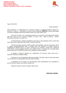
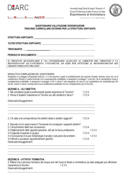
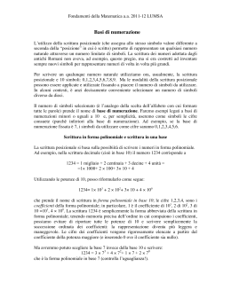
BAG2 AP
IT ISTRUZIONI PER L’INSTALLATORE E PER IL
2
SERVIZIO TECNICO DI ASSISTENZA
FR MANUEL
D’INSTRUCTION
POUR
L’INSTALLATEUR ET LE SERVICE APRÈSVENTE
12
UK INSTRUCTIONS FOR THE INSTALLER AND
22
THE TECHNICAL ASSISTANCE SERVICE
DE ANLEITUNGEN FÜR DEN INSTALLATEUR UND
32
DEN WARTUNGSDIENST
NL HANDLEIDING VOOR DE INSTALLATEUR EN
DE DIENST NA VERKOOP
42
CONFORMITÀ
Il BAG2 AP è conforme a:
●
Direttiva Bassa Tensione 2006/95/CE
●
Direttiva Compatibilità Elettromagnetica 89/336/CE
Gentile Cliente,
La ringraziamo per aver preferito il BAG2 AP un prodotto innovativo, moderno, di qualità, in grado di assicurarLe il
massimo benessere per lungo tempo con elevata affidabilità e sicurezza; in modo particolare se il BAG2 AP e la caldaia
alla quale è collegato saranno affidati ad un Servizio Tecnico di Assistenza Riello, che è specificatamente preparato ed
addestrato per effettuare la manutenzione periodica, così da mantenerli al massimo livello di efficienza, con minori
costi di esercizio e che dispone, in caso di necessità, di ricambi originali.
Questo libretto di istruzione contiene importanti informazioni e suggerimenti che devono essere osservati per una più
semplice installazione ed il miglior uso possibile del BAG2 AP.
Rinnovati ringraziamenti.
Riello S.p.A.
INDICE
GENERALE
Avvertenze generali
Regole fondamentali di sicurezza
Descrizione dell’apparecchio
Struttura
Identificazione
Dati tecnici
Circuito idraulico
Circolatore
Schemi elettrici
pag.
“
“
“
“
“
“
“
“
3
3
4
4
4
4
5
5
6
INSTALLATORE
Ricevimento del prodotto
Dimensioni e peso
Installazione dell’apparecchio
Schema installazione tipica
Collegamenti idraulici
Collegamenti elettrici
pag.
“
“
“
“
“
6
6
7
8
9
10
SERVIZIO TECNICO DI ASSISTENZA
Prima messa in servizio
Pompa di circolazione
Collegamento termostato limite bassa temperatura
Impostazione impianto alta temperatura
pag.
“
“
“
11
11
11
11
In alcune parti del libretto sono utilizzati i simboli:
ATTENZIONE = per azioni che richiedono particolare cautela ed adeguata preparazione
VIETATO = per azioni che NON DEVONO essere assolutamente eseguite
AVVERTENZA PER L’UTENTE: questo dispositivo non necessita di alcuna regolazione o controllo da parte dell’utente.
È pertanto vietato aprire il coperchio frontale del dispositivo.
Controllare periodicamente in caldaia la pressione dell’acqua nell’impianto, in caso di necessità ripristinare la pressione come da libretto istruzioni.
Se si dovessero verificare cali di pressione frequenti, chiedere l’intervento di personale professionalmente qualificato
che verificherà lo stato del vostro impianto.
2
AVVERTENZE GENERALI
Dopo aver tolto l’imballo assicurarsi dell’integrità
e della completezza della fornitura ed in caso di
non rispondenza, rivolgersi all’Agenzia
che
ha venduto l’apparecchio.
L’installazione dell’apparecchio deve essere effettuata da impresa abilitata ai sensi della Legge
5 Marzo 1990 n°46 che a fine lavoro rilasci al
proprietario la dichiarazione di conformità di installazione realizzata a regola d’arte, cioè in ottemperanza alle Norme vigenti ed alle indicazioni fornite dalla
nel presente libretto di istruzione.
Si consiglia all’installatore di istruire l’utente sul
funzionamento dell’apparecchio e sulle norme fondamentali di sicurezza.
L’apparecchio deve essere destinato all’uso previsto dalla
per il quale è stato espressamente realizzato. È esclusa qualsiasi responsabilità contrattuale ed extracontrattuale della
per danni causati a persone, animali o
cose, da errori d’installazione, di regolazione, di
manutenzione e da usi impropri.
oppure perServizio Tecnico di Assistenza
sonale professionalmente qualificato.
Il non utilizzo dell’apparecchio per un lungo periodo comporta l’effettuazione almeno delle seguenti operazioni:
- posizionare l’interruttore principale dell’apparecchio e quello generale dell’impianto su “spento”
- chiudere i rubinetti del combustibile e dell’acqua dell’impianto termico
- svuotare l’impianto termico e quello sanitario se
c’è pericolo di gelo.
La manutenzione deve essere eseguita almeno
una volta all’anno.
Questo libretto è parte integrante dell’apparecchio e di conseguenza deve essere
conservatocon cura e dovranno SEMPRE accompagnare il prodotto anche in caso di sua cessione ad altro proprietario o utente oppure di un trasferimento su un altro impianto. In caso di danneggiamento o smarrimento richiederne un altro
esemplare al Servizio Tecnico di Assistenza
di Zona.
In caso di fuoriuscite d’acqua chiudere l’alimentazione idrica ed avvisare, con sollecitudine, il
REGOLE FONDAMENTALI DI SICUREZZA
Ricordiamo che l’utilizzo di prodotti che impiegano
combustibili, energia elettrica ed acqua comporta
l’osservanza di alcune regole fondamentali di sicurezza quali:
È vietata qualsiasi operazione di pulizia prima di
aver scollegato l’apparecchio dalla rete di alimentazione elettrica posizionando l’interruttore generale dell’impianto su “spento”.
È vietato l’uso dell’apparecchio ai bambini ed alle
persone inabili non assistite.
È vietato modificare i dispositivi di sicurezza o
di regolazione senza l’autorizzazione e le indicazioni del costruttore dell’apparecchio.
È vietato azionare dispositivi o apparecchi elettrici quali interruttori, elettrodomestici ecc. se si
avverte odore di combustibile o di incombusti.
In questo caso:
- aerare il locale aprendo porte e finestre
- chiudere il dispositivo d’intercettazione del combustibile
- fare intervenire con sollecitudine il Servizio Tecnico di Assistenza
oppure personale professionalmente qualificato.
È vietato toccare l’apparecchio se si è a piedi
nudi e con parti del corpo bagnate.
È vietato tirare, staccare, torcere i cavi elettrici
fuoriuscenti dall’apparecchio anche se questa è
scollegata dalla rete di alimentazione elettrica.
È vietato tappare o ridurre dimensionalmente le
aperture di aerazione del locale di installazione,
se sono presenti.
È vietato lasciare contenitori e sostanze infiammabili nel locale dove è installata l’apparecchio.
È vietato disperdere e lasciare alla portata dei
bambini il materiale dell’imballo in quanto può essere potenziale fonte di pericolo.
GENERALE
3
DESCRIZIONE DELL’APPARECCHIO
BAG 2 AP, è un disgiuntore idrico da utilizzare in
abbinamento a qualsiasi caldaia.
Trova applicazione quale separatore idraulico tra generatore e impianto quando quest’ultimo richiede
portate più elevate di quelle fornite dal generatore
stesso.
Può essere installato a incasso, quindi senza nessun
ingombro esterno, oppure a parete (pensile).
STRUTTURA
1
Circolatore impianto alta temperatura
2
Bottiglia di miscela
3
4
Valvola di sfiato aria
Termometro impianto alta temperatura
5
Scatola connessioni elettriche
IDENTIFICAZIONE
Il BAG2 AP è identificabile attraverso:
- Etichetta imballo
DATI TECNICI
Alimentazione elettrica
Potenza massima assorbita dal BAG2 AP
Temperatura di funzionamento
Grado di protezione elettrica pensile
Grado di protezione elettrica incasso
Pressione massima
4
GENERALE
230(±10%)-50
135
0 ÷ +90
IP10D
IPX4D
3
V-Hz
W
°C
bar
CIRCUITO IDRAULICO
E
U
E - Entrata (3/4”)
U - Uscita (3/4”)
MD - Mandata impianto diretto (1”)
RD - Ritorno impianto diretto (1”)
La lunghezza massima dei collegamenti
idraulici tra caldaia e BAG2 AP non deve superare i 15 m.
RD
MD
CIRCOLATORE
Al primo avviamento e almeno ogni anno é utile
controllare la rotazione dell’albero del circolatore
in quanto, soprattutto dopo lunghi periodi di non
funzionamento, depositi e/o residui possono impedirne la libera rotazione.
È vietato far funzionare il circolatore senza acqua.
Nel caso in cui fossero presenti nel circuito dei
dispositivi di intercettazione della portata (valvole di zona termostatiche, elettrotermiche, motorizzate, ecc..) è consigliato prevedere l’inserimento di un by-pass sul collettore.
7,5
7,0
Prevalenza residua (m.C.A.)
Il BAG2 AP è equipaggiato di un circolatore le cui prestazioni, da utilizzare per il dimensionamento degli impianti, sono riportate nel grafico.
6,5
6,0
5,5
5,0
4,5
4,0
3,5
3
3,0
2,5
2,0
2
1,5
1,0
1
0,5
0,0
0
200
400
600
800
1000
1200
1400
1600
1800
2000
2200
2400
Portata impianto (l/h)
1 - prima velocità
2 - seconda velocità
3 - terza velocità
GENERALE
5
SCHEMI ELETTRICI
RICEVIMENTO DEL PRODOTTO
Il BAG2 AP viene fornito in collo unico protetto da un
imballo in cartone all’interno del quale si trova una busta
di plastica che contiene:
- Libretto istruzioni
- Certificato di garanzia
- N. 6 etichette matricola
Trovate inoltre all’interno del collo:
- Busta di plastica con tasselli ad espansione
DIMENSIONI E PESO
DESCRIZIONE
6
L
440
mm
P
160
mm
H
616
mm
Peso netto
14
kg
GENERALE
INSTALLAZIONE DELL’APPARECCHIO
Il BAG2 AP può essere installato “a parete” (pensile)
oppure “ad incasso” e può essere ubicato in prossimità della caldaia o in posizione remota purché la lunghezza dei collegamenti idraulici ed elettrici, tra caldaia e BAG2 AP non superi 15 metri.
BAG2 AP può essere installato in luoghi esposti ad
agenti atmosferici (pioggia, sole, gelo, ecc) solo ed
esclusivamente “a incasso”.
Installazione “a parete” (pensile)
Quando il BAG 2 AP viene installato “a parete” va
supportato con due tasselli ad espansione (forniti a
corredo) adeguati al tipo di parete ed al peso dell’apparecchio.
Si consiglia l’utilizzo di passatubi da posizionare sull’incasso per limitare le infiltrazioni di acqua.
I passatubi non sono forniti con il dispositivo.
Grado di protezione IP10D.
Installazione “a incasso”
Quando il BAG2 AP viene installato ad “incasso” è
necessario:
- predisporre le opere murarie realizzando una nicchia
di contenimento adatta alle dimensioni del BAG2 AP
ed allo spessore della parete (valori indicativi minimi riportati in figura)
- posizionare il BAG2 AP nella propria sede ricordandosi di aprire le due alette di sostegno per un migliore fissaggio
- proteggere i bordi laterali e il coperchio frontale durante i lavori di incasso del dispositivo.
Poiché gli allacciamenti idraulici ed elettrici tra impianto e BAG2 AP devono avvenire all’interno degli ingombri del dispositivo stesso, occorre prima posizionare il
BAG2 AP e poi i tubi di ingresso ed uscita dell’impianto e la canalizzazione dei cavi elettrici.
Grado di protezione IPX4D.
alette
INSTALLATORE
7
SCHEMA INSTALLAZIONE TIPICA
La figura mostra un esempio di installazione del
BAG2 AP.
NOTA: Per l’installazione di eventuali rubinetti (non forniti) occorre predisporre la nicchia di dimensione tale
da poterli installare sotto il BAG2 AP stesso.
8
INSTALLATORE
COLLEGAMENTI IDRAULICI
Prima di effettuare gli allacciamenti tutte le tubature
devono essere accuratamente lavate per rimuovere
eventuali residui che potrebbero compromettere il buon
funzionamento del BAG2 AP.
Gli allacciamenti idraulici verso caldaia e verso impianto devono essere eseguiti in modo razionale riferendosi alla figura.
Gli allacciamenti possono avvenire direttamente utilizzando gli attacchi femmina presenti sui tubi di mandata e ritorno del BAG2 AP o con l’interposizione su
lato impianto di eventuali rubinetti di intercettazione
(non forniti).
Tali rubinetti risultano molto utili all’atto della manutenzione perché permettono di svuotare solo il BAG2 AP
senza dover svuotare anche l’intero impianto.
Verificare che il vaso d’espansione della caldaia
sia di capacità adeguata alle dimensioni dell’impianto.
TA
caldaia
Tamponare i fori di fissaggio dei tubi per prevenire eventuali infiltrazioni d’acqua.
TA
termostato
ambiente
impianto
1234
1234
1234
1234
1234
1234
1234
1234
1234
1234
1234
1234
1234
1234
1234
1234
1234
1234
1234
1234
1234
1234
1234
1234
1234
1234
1234
1234
1234 SE
1234
1234Sonda
1234
esterna
1234
1234
1234
1234
1234
1234
1234
1234
1234
1234
1234
1234
1234
1234
1234
1234
1234
1234
1234
1234
1234
1234
1234
1234
1234
1234
1234
1234
1234
1234
1234
1234
1234
1234
1234
1234
1234
1234
1234
1234
1234
1234
1234
1234
1234
1234
1234
1234
1234
1234
1234
1234
1234
1234
1234
1234
1234
1234
1234
1234
1234
1234
1234
1234
1234
1234
1234
1234
1234
1234
1234
1234
1234
1234
1234
1234
1234
1234
1234
1234
1234
1234
INSTALLATORE
9
COLLEGAMENTI ELETTRICI
Per effettuare il collegamento elettrico del BAG2 AP è
necessario accedere all’interno del BAG2 AP stesso e
alla morsettiera di caldaia.
Per accedere al BAG2 AP:
- togliere il pannello lamierato anteriore del BAG2 AP
(fig. 1)
COLLEGAMENTO DEL BAG2 AP ALL’ALIMENTAZIONE ELETTRICA
Collegare il BAG2 AP all’alimentazione elettrica (fase
neutro-terra) utilizzando il cavo in dotazione.
È tassativamente vietato prelevare l’alimentazione elettrica del BAG2 AP dalla caldaia in quanto
il fusibile di caldaia non è dimensionato per i carichi elettrici del BAG2 AP.
COLLEGAMENTO TERMOSTATI AMBIENTE (TA)
Il TA dell’impianto deve essere collegato direttamente
al BAG2 AP (fig. 2) utilizzando un cavo con sezione
minima di 1 mm2.
Il carico rappresentato dalla pompa graviterà direttamente sul relativo termostato ambiente, quindi il contatto del TA deve essere adeguato all’applicazione e
essere compatibile con la portata elettrica delle pompe (si consiglia non inferiore a 230 Vac 50 Hz 6A).
fig. 1
fig. 2
COLLEGAMENTO BAG2 AP ALLA CALDAIA
Collegare il mammut B-B del BAG 2 AP (fig. 3) al
mammut TA della caldaia utilizzando un cavo min 2x0,5
mm2 (riferirsi allo schema elettrico sul libretto istruzioni per l’installatore della caldaia specifica).
fig. 3
In caso di alimentazione fase-fase verificare con
un tester quale dei due fili ha potenziale maggiore
rispetto alla terra e collegarlo alla L, in egual
maniera collegare il filo rimanente alla N.
Per alimentazioni flottanti, ovvero prive all’origine
di riferimento a terra è necessario l’utilizzo di un
trasformatore di isolamento con secondario ancorato a terra.
È obbligatorio:
- L’impiego di un interruttore magnetotermico
onnipolare, sezionatore di linea, conforme alle
Norme CEI-EN 60335-1 (apertura dei contatti di
almeno 3,5mm, categoria III)
- Utilizzare cavi di sezione ≥ 1,5mm2 e rispettare
il collegamento L (Fase) - N (Neutro)
10
INSTALLATORE
- L’amperaggio dell’interruttore deve essere adeguato alla potenza elettrica della caldaia, riferirsi ai dati tecnici per verificare la potenza elettrica
del modello installato
- Collegare l’apparecchio ad un efficace impianto
di terra
- Salvaguardare l’accessibilità alla presa di corrente dopo l’installazione
È vietato l’uso dei tubi del gas e dell’acqua per la
messa a terra dell’apparecchio.
Il costruttore non è responsabile di eventuali danni
causati dalla mancanza di messa a terra o dall’inosservanza di quanto riportato negli schemi
elettrici.
PRIMA MESSA IN SERVIZIO
Prima di avviare il BAG2 AP verificare la corretta esecuzione dei collegamenti idraulici ed elettrici.
Durante la fase di collaudo è possibile verificare la
temperatura dell’impianto mediante l’utilizzo del termometro indicato nella figura a lato.
POMPA DI CIRCOLAZIONE
Il BAG2 AP è fornito di circolatore con regolatore a tre
velocità.
Scegliere la velocità opportuna in base alle caratteristiche specifiche dell’impianto.
EVENTUALE SBLOCCAGGIO DELLA POMPA
Se dopo un lungo periodo di inattività il circolatore fosse bloccato è necessario svitare i tappi anteriori e
fare girare l’albero motore del circolatore con cacciavite.
Effettuare l’operazione con estrema cautela per non
danneggiare i componenti stessi.
IMPOSTAZIONE IMPIANTO ALTA TEMPERATURA
Impostare il selettore di temperatura riscaldamento
della caldaia al valore desiderato per l’impianto alta
temperatura.
COLLEGAMENTO TERMOSTATO LIMITE BASSA TEMPERATURA
(non fornito in dotazione)
Nel caso di installazioni del BAG2 AP su impianti a
bassa temperatura si consiglia l’utilizzo di un termostato limite di sicurezza da posizionare sulla mandata
dell’impianto a valle del BAG2 AP.
SERVIZIO TECNICO DI ASSISTENZA
11
CONFORMITÉ
Les BAG2 APsont conformes aux normes suivantes:
•
Norme Basse Tension 2006/95/CEE
•
Norme Compatibilité Electromagnétique 89/336/CEE
GENERALE
Avertissements
Normes de sécurité de base
Description de l’appareil
Structure
Données techniques
Circuit hydraulique
Circulateur
Schéma électrique
pag.
“
“
“
“
“
“
“
13
13
14
14
14
15
15
16
INSTALLATEUR
Réception du produit
Dimensions et poids
Montage de l’appareil
Schéma du montage type
Raccordements hydrauliques
Branchements électriques
pag.
“
“
“
“
“
16
16
17
18
19
20
SERVICE APRÈS-VENTE
Première mise en service
Pompe de circulation
Connexion thermostat limite basse température
Réglage installation haute température
pag.
“
“
“
21
21
21
21
Les symboles suivants ont été utilisés:
ATTENTION= opérations qui demandent une prudence particulière et une compétence adéquate.
IL EST INTERDIT= opérations qui NE DOIVENT ABSOLUMENT PAS être effectuées.
AVERTISSEMENT POUR L’UTILISATEUR
Ce dispositif n’a besoin d’être ni réglé ni contrôlé par l’utilisateur.
Il est donc interdit d’ouvrir le couvercle avant du dispositif.
Contrôlez à intervalles réguliers dans la chaudière la pression de l’eau de l’installation; en cas de besoin
rétablissez la pression en suivant les indications du mode d’emploi.
Si la pression chute fréquemment, demandez l’intervention du personnel qualifié qui vérifiera l’état de
votre installation.
12
AVERTISSEMENTS
Après avoir retiré l’emballage, s’assurer que la
fourniture est intègre et complète et en cas
contraire s’adresser à l’Agence qui a vendu
l’appareil.
L’installation de l’appareil doit être effectuée par
un professionnel qualifié qui donne au propriétaire
à la fin du travail la déclaration de conformité
d’installation réalisée dans les règles de l’art, c’est
à dire suivant les normes en vigueur.
Il est conseillé à l’installateur d’informer
l’utilisateur sur le fonctionnement de l’appareil et
sur les normes fondamentales de sûreté.
L’appareil ne doit être destiné qu’à l’usage prévu
et pour son utilisation stricte. Toute responsabilité
contractuelle et extra-contractuelle de la part du
constructeur pour des dommages causés à des
personnes, animaux ou choses, des erreurs
d’installation, de réglage, d’entretien et
d’utilisations impropres est exclue.
La non-utilisation de l’appareil pour une longue
période nécessite l’intervention du Service Après
Vente ou du personnel qualifié qui doit effectuer
au moins les opérations suivantes:
• positionner l’interrupteur principal de l’appareil
et l’interrupteur général de l’installation sur “éteint”
• fermer les robinets du combustible et de l’eau
de l’installation thermique
• vider l’installation thermique et sanitaire en cas
de risque de gel.
L’entretien de l’appareil doit être réalisé au moins
une fois par an.
Ce livret constitue partie intégrante de l’appareil
et par conséquent doit être soigneusement gardé
et il devra toujours accompagner l’appareil en cas
de cession à un autre propriétaire ou usager ou
bien de transfert sur une autre installation. En
cas de détérioration ou de per te il faudra
demander un autre exemplaire.
En cas de fuite d’eau fermer l’alimentation
hydraulique et prévenir, immédiatement, le
Service Après-vente ou bien le personnel qualifié.
NORMES DE SECURITE DE BASE
Il est à rappeler que l’utilisation des produits qui utilisent
des combustibles, énergie électrique et eau entraîne
le respect de quelques normes de base de sécurité,
telles que:
Il est interdit l’utilisation de l’appareil aux enfants.
réseau d’alimentation électrique en positionnant
l’interrupteur général de l’installation sur “arrêt”.
Il est interdit de modifier les dispositifs de sécurité
ou de réglage sans l’autorisation et les indications
du constructeur.
Il est interdit d’actionner des dispositifs ou des
appareils électriques tels qu’interrupteurs,
électroménagers, etc. en cas d’odeur de
combustibles ou de gaz.
Il faut:
• aérer la pièce en ouvrant portes et fenêtres
• fermer le dispositif d’interception du combustible
ou du gaz
• faire intervenir promptement le Service
Aprèsvente ou bien le personnel qualifié.
Il est interdit de tirer, détacher, tordre les câbles
électriques sortant de l’appareil même s’il est
déconnecté du réseau d’alimentation électrique.
Il est interdit de toucher l’appareil les pieds nus
ou avec des parties du corps mouillées.
Il est interdit de disperser, abandonner ou laisser
à la portée des enfants le matériel d’emballage
(carton, agrafes, sachets en plastique, etc.) afin
d’éviter tout danger potentiel.
Il est interdit d’entreprendre toute opération de
nettoyage avant d’avoir débranché l’appareil du
Il est interdit de boucher ou réduire les dimensions
des ouvertures d’aération du lieu d’installation,
si elles sont prévues.
Il est interdit de laisser récipients et substances
inflammables où l’appareil est installé.
GENERALE
13
DESCRIPTION DE L’APPAREIL
BAG² AP est un disjoncteur hydraulique utilisable avec
n’importe quelle chaudière.
Il sert de séparateur hydraulique entre le générateur
et l’installation lorsque cette dernière exige des débits
supérieurs à ceux qui sont fournis par le générateur
même.
Il peut être encastré (aucun encombrement extérieur)
ou mural (suspendu).
STRUCTURE
1
2
3
4
5
Circulateur installation haute température
Bouteille de mélange
Vanne de purge d’air
Thermomètre installation haute température
Boîtier de branchements électriques
DONNÉES TECHNIQUES
Alimentation électrique
Puissance maximum absorbée par le BAG2 AP
Température de fonctionnement
Degré de protec. électr. montage au mur (suspendu)
Degré de protection électr. montage encastré
Pression max
14
GENERALE
230(±10%)-50
135
0 ÷ +90
IP10D
IPX4D
3
V-Hz
W
°C
bar
CIRCUIT HYDRAULIQUE
E
EUMD RD -
U
Entrée (3/4”)
Sortie (3/4”)
Dèpart installation directe (1”)
Dèpart installation directe (1”)
La longueur des raccordements hydrauliques
entre la chaudière et le BAG2 AP ne dépasse
pas 15 mètres.
RD
MD
CIRCULATEUR
Lors de la première mise en marche et une fois
par an au moins, nous vous conseillons de faire
tourner l’arbre des circulateurs, après de longues
périodes d’inactivité.
Il est strictement interdit de faire fonctionner les
circulateurs sans eau.
Si dans le circuit sont présents des dispositifs
de variation du débit (vannes de zone
thermostatiques, électrothermiques, motorisées,
etc..) on conseille de prévoir un by-pass sur le
collecteur.
7,5
Prévalence résiduelle (m.C.A.)
Le BAG2 AP est équipé d’un circulateur dont les
caractéristiques, servant à dimensionner les
installations, sont indiquées sur le graphique.
7,0
6,5
6,0
5,5
5,0
4,5
4,0
3,5
3
3,0
2,5
2,0
2
1,5
1,0
1
0,5
0,0
0
200
400
600
800
1000
1200
1400
1600
1800
2000
2200
2400
Débit (l/h)
1 - première vitesse
2 - deuxième vitesse
3 - troisième vitesse
GENERALE
15
SCHEMA ELECTRIQUE
NE: noir
BL: bleu
MA: marron
GI/VE: jaune/vert
RÉCEPTION DU PRODUIT
Le BAG2 AP est fourni dans un seul colis protégé par
un emballage en carton, à l’intérieur duquel se trouve
aussi un sachet en plastique contenant:
- Mode d’emploi
- Certificat de garantie
- 6 étiquettes du matricule
Vous trouverez aussi dans le carton:
- sachet en plastique contenant les chevilles à
expansion.
DIMENSIONS ET POIDS
DESCRIPTION
16
L
440
mm
P
160
mm
H
616
mm
Poids net
14
kg
GENERALE
MONTAGE DE L’APPAREIL
Le BAG2 AP peut être monté au mur (suspendu) ou
encastré, à proximité de la chaudière ou à distance à
condition que la longueur des branchements électriques
et des raccordements hydrauliques entre la chaudière
et le BAG2 AP ne dépassent pas 15 mètres.
BAG2 AP peut être monté dans un endroit exposé aux
intempéries (pluie, soleil, gel, etc..) seulement
«encastré».
Montage au mur (suspendu)
Si vous montez le BAG2 AP au mur, vous devez le
soutenir à l’aide de deux chevilles (fournies) adaptées
au type de mur et au poids de l’appareil.
Nous vous conseillons d’utiliser des fourreaux, que
vous placerez sur l’encastrement afin de limiter les
infiltrations d’eau.
Les fourreaux ne sont pas fournis.
Degré de protection IP10D.
Montage encastré
Si vous encastrez le BAG2 AP vous devez:
- Préparer la maçonnerie en formant une niche ayant
les dimensions requises par le BAG2 AP et l’épaisseur
du mur (valeurs possibles minimum indiquées sur la
figure).
- Placer le BAG2 AP dans son logement sans oublier
d’ouvrir les deux ailettes de support pour consolider
la fixation.
- Protéger les bords latéraux et le couvercle frontal
pendant les travaux d’encastrement du dispositif.
Les branchements électriques et les raccordements
hydrauliques entre l’installation et le BAG2 AP doivent
être réalisés à l’intérieur du dispositif, vous devez tout
positionner le BAG2 AP en amont des tuyaux d’entrée
et de sortie de l’installation et de la gaine des câbles
électriques.
Degré de protection IPX4D.
ailettes
INSTALLATEUR
17
SCHÉMA DU MONTAGE TYPE
La figure ci-contre illustre un exemple de montage
du BAG2 AP
REMARQUE: Pour monter les robinets éventuels (non
fournis), préparez une niche de dimensions appropriées
à leur installation sous le BAG2 AP.
18
INSTALLATEUR
RACCORDEMENTS HYDRAULIQUES
Avant de réaliser les raccordements hydrauliques,
lavez soigneusement toutes les tuyauteries pour
éliminer les résidus susceptibles de gêner le
fonctionnement du BAG2 AP.
Les raccordements hydriques vers la chaudière et vers
l’installation doivent s’effectuer en suivant les cotes
de la figure.
Les raccordements peuvent s’effectuer directement à
l’aide des raccords femelles placés sur les tuyaux de
refoulement et de retour du BAG2 AP ou en intercalant
éventuellement du côté installation des robinets d’arrêt
(non fournis).
Ces robinets sont très utiles au cours des opérations
d’entretien car ils permettent de ne vider que le BAG2
AP sans vidanger toute l’installation.
TA
chaudière
Vérifiez si le vase d’expansion de la chaudière a
une capacité adaptée aux dimensions de
l’installation.
TA
Thermostat
d’ambiance
Installation
1234
1234
1234
1234
1234
1234
1234
1234
1234
1234
1234
1234
1234
1234
1234
1234
1234
1234
1234
1234
1234
1234
1234
1234
1234
1234
1234
1234 SE
1234
1234Sonde
1234
1234
1234extérieure
1234
1234
1234
1234
1234
1234
1234
1234
1234
1234
1234
1234
1234
1234
1234
1234
1234
1234
1234
1234
1234
1234
1234
1234
1234
1234
1234
1234
1234
1234
1234
1234
1234
1234
1234
1234
1234
1234
1234
1234
1234
1234
1234
1234
1234
1234
1234
1234
1234
1234
1234
1234
1234
1234
1234
1234
1234
1234
1234
1234
1234
1234
1234
1234
1234
1234
1234
1234
1234
1234
1234
1234
1234
1234
1234
1234
1234
1234
1234
1234
1234
INSTALLATEUR
19
BRANCHEMENTS ÉLECTRIQUES
Pour effectuer la connexion électrique du BAG2 AP il
faut accéder à l’intérieur du BAG2 AP et à la boîte à
bornes de la chaudière.
Pour accéder au BAG2 AP:
- enlever le panneau en tôle antérieur du BAG2 AP
BRANCHEMENT DU BAG² AP À L’ALIMENTATION
ÉLECTRIQUE
Brancher le BAG² AP à l’alimentation électrique (phase
neutre-terre) à l’aide du câble fourni.
fig. 1
Il est formellement interdit de prélever
l’alimentation électrique du BAG² AP sur la
chaudière car son fusible ne supporte pas les
charges électriques du BAG² AP
BRANCHEMENT THERMOSTATS D’AMBIANCE (TA)
Le TA de l’installation doive être directement relie au
BAG² AP (fig. 2) à l’aide d’un câble d’une section
minimum de 1 mm². La charge de la pompe pèsera
directement sur le thermostat d’ambiance
correspondant. Le contact du TA doit donc être
approprié à cette application et compatible avec le
débit électrique des pompes (il est conseillé de n’avoir
pas moins de 230 Vac 50 Hz 6A).
BRANCHEMENT À LA CHAUDIÈRE
Brancher les bornes B-B du BAG² AP (fig. 3) sur le
bornier TA de la chaudière à l’aide d’un câble d’un
minimum de 2x0,5 mm² (voir le schéma sur le manuel
d’utilisation pour l’installateur de la chaudière
spécifique).
En cas d’alimentation phase-phase vérifier à l’aide
d’un testeur lequel des deux fils a un potentiel plus
élevé par rapport à la terre et le relier à L., de même
relier le fil qui reste à N.
Pour les alimentations flottantes, c’est-à-dire
dépourvues de mise à la terre, vous devez utiliser
un transformateur d’isolation avec un secondaire
ancré à la terre.
Il est obligatoire:
- l’emploi d’un interrupteur magnétothermique
omnipolaire, sectionneur de ligne, conforme aux
Normes CEI-EN 60335-1 (ouverture des contacts
d’au moins 3,5 mm, catégorie III)
- Utiliser des câbles de section > 1,5 mm_ et de
respecter la connexion L (Phase) - N (Neutre)
20
INSTALLATEUR
fig. 2
fig. 3
- L’’ampérage de l’interrupteur doit être adapté à
la puissance électrique de la chaudière. Consultez
les données techniques pour vérifier la puissance
électrique du modèle installé.
- Réaliser une connexion de terre efficace
- Protéger l’accès à la prise de courant après le
montage
Il est interdit l’emploi de tuyaux du gaz et de l’eau
pour la mise à la terre de l’appareil.
Le constructeur n’est pas responsable de tout
endommagement causé par le manque de la mise
à la terre ou provenant du manque de respect de
les schémas électriques.
PREMIÈRE MISE EN SERVICE
Avant de démarrer le BAG 2 AP vérifiez si les
raccordements hydrauliques et les branchements
électriques sont effectués correctement.
Le thermostat indiqué sur la figure permettent de vérifier
la température pendant la phase d’essai.
POMPE DE CIRCULATION
2
Le BAG AP est équipé d’un circulateur muni de
régulateur à trois vitesses.
Choisissez la vitesse opportune en fonction des
caractéristiques spécifiques des installations.
DÉVERROUILLAGE ÉVENTUEL DE POMPE
Si le circulateur se verrouille après une longue période
d’inactivité, dévissez les bouchons antérieurs et faites
tourner l’arbre moteur de circulateur avec un tournevis.
Procédez très prudemment pour ne pas endommager
les composants.
RÉGLAGE INSTALLATION HAUTE TEMPÉRATURE
Mettre le sélecteur de température de chauffage de la
chaudière sur la valeur désirée pour l’installation haute
température.
CONNEXION THERMOSTAT LIMITE BASSE TEMPERATURE
(pas présent dans l’équipement fourni)
En cas d’installations du BAG2 AP sur des systèmes
à basse température on conseille l’emploi d’un
thermostat limite de sécurité à positionner sur le
refoulement du système en aval du BAG2 AP.
SERVICE APRES-VENTE
21
CONFORMITY
BAG2 AP conforms to:
●
Low Voltage Directive 2006/95/EEC
●
Electromagnetic Compatibility Directive 89/336/EEC
GENERAL
Warnings and safety considerations
Description of the equipment
Structure
Technical data
Hidraulic circuit
Circulator
Wiring Diagrams
Page
“
“
“
“
“
“
23
24
24
24
25
25
26
INSTALLATOR
Product content
Dimensions and weight
Installation of the appliance
Typical installation layout
Hydraulic connections
Electrical connections
Page
“
“
“
“
“
26
26
27
28
29
30
TECHNICAL SERVICE
First starting up
Circulation pump
High limit thermostat low temperature connection
High temperature appliance setting
Page
“
“
“
31
31
31
31
This instruction manual is an integral part of the manual for the boiler to which the BAG2 AP unit is connected.
See the latter manual for GENERAL WARNINGS and BASIC SAFETY RULES and other specific information on the
functioning of the boiler.
The following symbols are used at some points in the manual:
WARNING= for actions that call for particular caution and adequate training.
FORBIDDEN= for actions that MUST NOT be carried out under any circumstances
WARNINGS FOR THE USER
This device does not require any setting or checking by the user. Opening the front cover on the device is
therefore forbidden.
Check the water pressure in the system from time to time. If necessary, alter the pressure as indicated in
the instruction manual.
If the pressure drops frequently, call in professionally trained personnel to check the status of your system.
22
WARNINGS AND SAFETY DEVICES
The boilers made in our factories are all built with
care being taken over each individual component
in order to protect both the user and the installer
from any accidents. We therefore urge trained
personnel to be particularly careful with the electrical connections on completion of each job done
on the product, especially as far as the bare parts
of the conductors are concerned. These must
not stick out of the terminal board in any way, so
as to avoid any possibility of contact with live
parts of the conductor itself.
Both this instruction manual and the user’s manual
are an integral part of the product. Make sure
that they always remain with the machine, even
if it is sold to another owner or user, or if it is
transferred to another plant. If it should get
damaged or lost, ask your local Technical
Assistance Service for another copy.
Installing the boiler and any other assistance and
maintenance work must be carried out by qualified
personnel in compliance with the relevant laws and
current standards.
We recommend that the installer instruct the user
on how the equipment works and on basic safety
standards.
The boiler must only be used for the purposes for
which it was expressly made. The manufacturer
does not accept any contractual or extracontractual responsibility for any damage caused
to people, animals, or property, due to incorrect
installation, setting, or maintenance, or due to
improper use.
On removing thùe packing, check the integrity
and completeness of the contents. Should any
discrepancies be found, contact the dealer that
sold you the equipment.
The drain from the equipment’s safety valve must
be connected to an adequate collection and
removal system. The manufacturer of this
equipment is not responsible for any damage
caused by the safety valve opening.
· Close the taps on the water and the fuel
supplies, for both the heating and the hot water
systems.
· Empty the heating and hot water systems if
there is any risk of freezing.
- Maintenance must be carried out on the boiler
at least once a year, and appointments must
be made timeously with the Technical
Assistance Service.
For your safety, remember that:
The boiler should not be used by children or people
that are unable to use it properly.
It is dangerous to activate devices or electrical
equipment such as switches, domestic
appliances, etc. if you smell any fuel or burning.
Should a gas leak occur, ventilate the room by
opening the doors and windows, shut the main
gas valve, call in professionally qualified personnel
from the Technical Assistance service immediately.
Do not touch the boiler when barefoot or when
parts of your body are wet or damp.
Before cleaning, disconnect the boiler from the
electricity mains by switching the bi-pole switch
for the plant and the main switch on the control
panel to “OFF”.
Any modifications to the safety and regulating
devices without prior authorisation or instructions
from the manufacturer are forbidden.
Do not pull on, disconnect, or twist the electrical
cables that come from the boiler, even when it is
disconnected from the electricity mains.
Do not block up or reduce the size of ventilation
openings in the room in which the unit is installed.
Do not leave containers or inflammable
substances in the room in which the equipment
is installed.
Do not leave any part of the packing within reach
of children.
During installation the user must be informed that:
- Should any water flow out, they are to shut off
the water supply and contact the Technical Assistance Service immediately.
- The working pressure for the plumbing system
must be between 1 and 2 bar, and must not
exceed 3 bar. Where necessary, professionally
qualified personnel from the Technical
Assistance Service must be called in.
- If the boiler is not to be used for a lengthy
period of time, we recommend calling in the
Technical Assistance Service to carry out the
following operations:
· Switch the main switch for the equipment and
the main switch for the entire plant to “off”.
GENERAL
23
DESCRIPTION OF THE EQUIPMENT
The BAG2 AP is a water separator that is to be used
with every boilers, where it separates the water in the
generator and in the plant, when the latter is
characterised by high flow rates that exceed those developed by the generator itself.
The BAG2 AP unit can be built into the wall, thereby
avoiding any protrusion, or it can be wall-mounted.
STRUCTURE
1
High temperature system pump
2
Mixing bottle
3
Air discharge valve
4
High temperature system thermometer
5
Electrical connection board
TECHNICAL DATA
Electrical power supply
Maximum power absorbed by the BAG2 AP
230(±10%)-50
135
V-Hz
W
Working temperature
0 ÷ +90
°C
Electrical protection level wall-mounted installation
Electrical protection level “built-in” installation
IP10D
IPX4D
Maximum pressure
24
GENERAL
3
bar
HYDRAULIC CIRCUIT
E
EUMD RD -
U
Inlet (3/4”)
Outlet (3/4”)
Delivery, direct system (1”)
Return, direct system (1”)
The maximum length of plumbing connections between the boiler and the
BAG2 unit must not exceed 15 m.
RD
MD
CIRCULATOR
2
The BAG AP is fitted with one circulator, the
performance data to be used to size the system, is shown in the graph.
7,5
7,0
6,5
Do not run the circulator without water.
Where present flo regulator devices
(thermostatic electrical or motorized zone
valves) it is better to inster a by pass on
the collector.
6,0
Residual head (m.C.A.)
When starting up for the first time, and at
least once a year, it is advisable to check
the pump shaft rotate.
This is necessary because, especially after lengthy periods of inactivity, deposits
and/or residue may stop it rotating freely.
5,5
5,0
4,5
4,0
3,5
3
3,0
2,5
2,0
2
1,5
1,0
1
0,5
0,0
0
200
400
600
800
1000
1200
1400
1600
1800
2000
2200
2400
Capacity (l/h)
1 - first speed
2 - second speed
3 - third speed
GENERAL
25
WIRING DIAGRAMS
Fusibile: Fuse
NE: black
BL: bleu
MA: brown
GI/VE: yellow/green
PRODUCT CONTENT
The BAG2 AP is supplied within a cardboard carton,
which contains:
- instruction manual
- warranty
- N. 6 serial number plates
In addition:
- plastic bag with fixing devices.
DIMENSIONS AND WEIGHT
DESCRIPTION
26
L
440
mm
P
160
mm
H
616
mm
Net weight
14
kg
GENERAL
INSTALLATION OF THE APPLIANCE
The BAG2 AP can be wall-mounted or “built-in” and can be
located near the boiler or at a distance, provided the length
of the plumbing and electrical connections between the
boiler and the BAG2 AP unit do not exceed 15 metres.
The BAG2 AP can be installed in positions exposed to the
weather (rain, sun, ice, etc.) only if in “built-in” installation.
Wall-mounted installation
When the BAG2 AP is wall-mounted it must be supported
by two expanding wall anchors (supplied) that are suitable
for the type of wall and weight of the equipment.
We recommend using pipe sleeves built into the wall in
order to limit the infiltration of water.
These pipe sleeves are not supplied with the unit.
Electrical protection level IP10D.
“Built-in” installation
When the BAG2 AP unit is built-in:
- Provide the building work, complete with a niche of
suitable size for the BAG2 AP to suit the thickness of the
wall (minimum indicative dimensions shown in the
figure).
- Position the BAG2 AP in position, and remember to open
out the two support lugs to fix it more securely.
- Protect the side edges and front while building in the
device.
Since the plumbing and electrical connections between
the system and the BAG2 AP must be contained within the
overall size of the device itself, first position the BAG2 AP
and then the entry and exit pipes for the system and the
conduiting for the electric cables.
Electrical protection level IPX4D.
rib
INSTALLER
27
TYPICAL INSTALLATION LAYOUT
The figure alongside shows a possible way of
installing the BAG2 AP.
NOTE: To allow for installing taps (not supplied) a niche
must be formed of sufficient size to allow them to be
fitted below the BAG2 AP itself.
28
INSTALLER
HYDRAULIC CONNECTIONS
Before forming the connections all the piping must be thoroughly flushes to remove any residue that could compromise the proper functioning of the BAG2 AP.
The plumbing connections to the boiler and the system
must be carried out rationally, as indicated in the figure.
Direct connections can be formed using the female couplings on the delivery and return pipes for the BAG2 AP, or
taps (not supplied) can be fitted on the lines for shutting off
the lines.
These taps are very useful when maintenance is carried
out, as they allow the BAG2 AP to be drained without having
to drain the entire system.
Check that the expansion vessel on the boiler has
sufficient capacity for the size of the system.
TA
boiler
TA
ambient
thermostat
installation
1234
1234
1234
1234
1234
1234
1234
1234
1234
1234
1234
1234
1234
1234
1234
1234
1234
1234
1234
1234
1234
1234
1234
1234
1234
1234
1234
1234
1234 SE
1234
1234External
1234
sensor
1234
1234
1234
1234
1234
1234
1234
1234
1234
1234
1234
1234
1234
1234
1234
1234
1234
1234
1234
1234
1234
1234
1234
1234
1234
1234
1234
1234
1234
1234
1234
1234
1234
1234
1234
1234
1234
1234
1234
1234
1234
1234
1234
1234
1234
1234
1234
1234
1234
1234
1234
1234
1234
1234
1234
1234
1234
1234
1234
1234
1234
1234
1234
1234
1234
1234
1234
1234
1234
1234
1234
1234
1234
1234
1234
1234
1234
1234
1234
1234
1234
1234
1234
INSTALLER
29
ELECTRIC CONNECTIONS
To form the electrical connections for the BAG2 AP,
access must be obtained to the internal terminal board
and the boiler card.
To gain access to the BAG2 AP:
- remove the front cover panel from the BAG2 AP
CONNECTING THE BAG2 AP TO THE ELECTRICITY
MAINS
BAG2 AP unit to the electricity mains (phase /neutral /
earth) using the cable supplied.
fig. 1
Drawing the power supply for the BAG2 AP from
theboiler is absolutely forbidden as the boiler’s fuse
is not sizedto take the electrical loads associated
with the BAG2 AP.
CONNECTING THE AMBIENT THERMOSTATS (TA)
The TA for the system must be directly connected to
the BAG2 AP (fig. 2) using a cable with minimum section
1 mm2.
The pump power load will be direclty supported by the
related TA, therefor the TA connection must be
adequately designed for this application and compatible
with the electrical features of the pumps (it is
recommanded not lower than 230 Vac 50 Hz 6A).
BAG2 AP CONNECTION TO THE BOILER
Connect the BAG2 AP socket B-B (fig. 3) to boiler TA
socket using a min 2x0,5 mm2 cable (refer to the electric
diagram on the boiler instrucion manual).
When using a phase-phase power supply, use a
tester to determine which of the two wires has the
greater potential compared to the earth and connect it to the L terminal. Connect the remaining wire
to the N terminal.
For floating power supplies, that is, those that have
no earth connection, an insulation transformer must
be used, with a secondary unit connected to the
earth.
The following are obligatory:
- A multi-pole trip-switch must be used to disconnect
the line, that conforms to the CEI-EN 60335-1 standards (contact opening at least 3,5mm, category III).
- Use cables with a 1,5 mm2 section and respect the
L (Phase) – N (Neutral) connection.
30
INSTALLER
fig. 2
fig. 3
- The amperage on the switch must be adequate
for the boiler’s electrical power rating – see the
technical data to check the electrical power rating
for the model installed.
- Connect the equipment to an efficient earthing
system.
- The power socket must be inaccessible after installation.
The use of gas or water pipes to earth this equipment is forbidden.
The manufacturer does not accept any responsibility for any damage caused due to the lack of a
proper earth or failure to comply with the wiring
diagram.
FIRST STARTING UP
Before switching the BAG2 AP on, check that the electrical and plumbing connections have been formed correctly.
During testing, the temperature can be checked due
to the thermometer shown in the figure.
CIRCULATION PUMP
The BAG2 AP is supplied with circulator with a threespeed control.
Choose the best speed to suit the specific characteristics of the systems.
RELEASING THE PUMP IF NECESSARY
If the unit has been inactive for a lengthy period of
time and the circulator are stuck, unscrew the caps on
the front and turn the shaft for the circulator motor
using a screwdriver.
Do this extremely carefully so as not to damage the
components themselves.
HIGH TEMPERATURE APPLIANCE SETTING
Fix the boiler central heating knob to the high temperature appliance desidered value.
HIGH LIMIT THERMOSTAT LOW TEMPERATURE CONNECTION
(not supplied)
In case of low temperature installation is strongly,
consult to install a safety high limit thermostat on the
delivery pipe beyond the BAG2 AP.
Make the high limit thermostat electrical connection
directly to the boiler terminal board.
TECHNICAL SERVICE
31
KONFORMITÄT
BAG2 AP wurde gemäß folgenden Vorschriften entworfen und hergestellt:
●
Niederspannungsrichtlinie 2006/95/EEC
●
Richtlinie bzgl. elektromagnetische Verträglichkeit 89/336/EEC
ALLGEMEINES
Allgemeine Anweisungen
Sicherheitsgrundregeln
Gerätebeschreibung
Struktur
Technische Angaben
Hydraulikkreislauf
Pumpenschieber
Schaltpläne
Seite
“
“
“
“
“
“
“
33
33
34
34
34
35
35
36
INSTALLATEUR
Produktempfang
Ausmaße und Gewicht
Geräteinstallation
Standardinstallationsplan
Hydraulikanschlüsse
Elektroanschlüsse
Seite
“
“
“
“
“
36
36
37
38
39
40
Seite
“
“
“
41
41
41
41
WARTUNGSDIENST
Erstinbetriebnahme
Umlaufpumpen
Anschluss grenzthermostat tief temperatur
Einstellung des hochtemperaturkreises
An manchen Stellen der Gebrauchsanleitung werden folgende Symbole benutzt:
ACHTUNG = für Tätigkeiten, die besondere Vorsicht und entsprechende Qualifikation benötigen
VERBOTEN = für Tätigkeiten, die AUF KEINEM FALL durchgeführt werden dürfen
HINWEIS FÜR DEN BENUTZER
Diese Vorrichtung benötigt keine Einstellung bzw. Kontrolle seitens des Benutzers.
Es ist daher verboten, den Frontdeckel der Vorrichtung zu öffnen.
Periodisch den Wasserdruck in der Anlage am Kessel überprüfen, im Bedarfsfall den Druck gemäß
Gebrauchsanleitung wiederherstellen.
Sollten häufige Druckabfälle vorkommen, den Eingriff seitens qualifiziertem Fachpersonal einholen, welcher
den Zustand des Gerätes überprüfen wird.
32
ALLGEMEINE ANWEISUNGEN
Nach dem Entfer nen der Ver packung sich
vergewissern, daß die Lieferung vollständig und
unversehrt ist. Sollte es dem nicht so sein, sich
an die Agentur die das Gerät verkauft hat wenden.
Die Installation des Gerätes muss durch
qualifiziert technisches Personal erfolgen, in
Übereinstimmung mit den gültigen Vorschriften.
Eine längere Stillstandzeit macht es notwendig,
zumindest folgende Tätigkeiten durchzuführen:
- die Hauptschalter des Gerätes und der Anlage
auf „aus“ stellen
- die Brennstoff- und Wasserhähne der
Wärmeanlage schließen
- die Wärme- und Sanitätsanlagen falls Frostgefahr
droht entleeren.
Es wird dem Installateur empfohlen, den Benutzer
über den Betrieb des Gerätes und den
Sicherheitsgrundnormen zu unterrichten.
Die Wartung muss mindestens einmal im Jahr
durchgeführt werden.
Das Gerät muss zu dem vorgesehenen Gebrauch
bestimmt werden, für den es ausdrücklich erzeugt
wurde. Jede vertragliche und außervertragliche
Haftung seitens für Personen-, Tieren oder
Sachschäden die durch Installations-,
Einstellungs-,
War tungsfehler
bzw.
missbräuchliche Verwendung verursacht wurden.
Diese Gebrauchsanleitung ist integrierender
Bestandteil des Gerätes und muss daher
sorgfältig aufbewahrt werden. Dieselbe muss das
Produkt auch bei Abgabe an einem anderen
Besitzer bzw. Benutzer oder Versetzung auf eine
andere Anlage IMMER begleiten. Bei
Beschädigung oder Verlust ein weiteres Exemplar
beim Zonenwartungsdienst anfragen.
Im Fall von Wasseraustritt die Wasserversorgung
schließen und schnellstmöglich Wartungsdienst
oder qualifiziertes Fachpersonal benachrichtigen.
SICHERHEITSGRUNDREGELN
Es wird daran erinner t, daß die Benutzung von
Produkten, die Brennstoffe, elektrische Energie und
Wasser verbrauchen, die Beachtung einiger
Sicherheitsgrundregeln einschließt, wie:
Es ist verboten, Reinigungstätigkeiten bevor man
das Gerät vom elektrischen Versorgungsnetz
durch Schalten auf „aus“ des Hauptschalters der
Anlage getrennt hat, durchzuführen.
Es ist verboten, das Gerät seitens Kinder und
nicht betreute behinder te Personen ist zu
benutzen.
Es ist verboten, die Sicherheits- bzw.
Regelungsvorrichtungen ohne Genehmigung und
Anweisungen vom Gerätehersteller zu ändern.
Es ist verboten, elektrische Vorrichtungen oder
Geräte wie Schalter, Elektrogeräte, usw. zu
betätigen, falls man Geruch von Brennstoff bzw.
Verbrennungsrückständen riecht.
In diesem Fall:
- den Raum durch öffnen von Fenstern und Türen
lüften
Es ist verboten, die aus dem Gerät austretenden
Elektrokabel zu ziehen, trennen, biegen, auch
wenn das Gerät selbst vom elektrischen
Versorgungsnetz getrennt ist.
Es ist verboten, die Lüftungsöffnungen des
Installationsraumes, falls anwesend, zu
verstopfen oder verkleinern.
- die Brennstoff-Fangschaltung schließen
- schnellstmöglich den Eingriff seitens des
War tungsdienstes
oder
qualifizier ten
Fachpersonals einholen.
Es ist verboten, entflammbare Behälter oder Stoffe im Raum wo das Gerät installiert ist, liegen zu
lassen.
Es ist verboten, das Gerät wenn man barfuss ist
oder mit nassen Körperteilen ist, zu berühren.
Es ist verboten, das Verpackungsmaterial zu
zerstreuen und in Greifweite von Kindern zu
lassen, da es eine potentielle Gefahrquelle
darstellt.
ALLGEMEINES
33
GERÄTEBESCHREIBUNG
BAG 2 AP ist ein inVerbindung mit jedem Boiler zu
benutzender Wasserauslöser. Wird als hydraulischer
Abscheider zwischen Generator und Anlage eingesetzt,
wenn letztere höhere Durchflussmengen als die vom
Generator selbst geliefer ten benötigt. Kann im
Einbaumodus, also ohne äußeren Raumbedarf oder
an der Wand (hängend) installiert werden.
STRUKTUR
1
Zirkulator Hochtemperaturkreis
2
Mischflasche
3
4
Entlüftungsventil
Thermometer Hochtemperaturkreis
5
Elektrische Anschlussdose
TECHNISCHE ANGABEN
Stromversorgung
Maximal vom BAG2 AP aufgenommene Leistung
Betriebstemperatur
34
230(±10%)-50
135
0 ÷ +90
Elektrischer Schutzgrad hängend
IP10D
Elektrischer Schutzgrad Einbaumontage
Druck - max.
IPX4D
3
ALLGEMEINES
V-Hz
W
°C
bar
HYDRAULIKKREISLAUF
E
U
E - Eintritt (3/4”)
U - Austritt (3/4”)
MD - Zufuhr Direktanlage (1”)
RD - Rücklauf Direktanlage (1”)
Die
Maximallänge
der
Hydraulikanschlüssen zwischen
Kessel und BAG2 AP darf nicht über
15 m sein.
RD
MD
PUMPENSCHIEBER
Das BAG 2 AP ist mit Pumpenschiebern
ausgerüstet, wessen Leistungen zur
Bemaßung der Anlagen gedacht und im
Diagramm dargestellt sind.
7,5
7,0
6,5
Es ist verboten, die Pumpenschieber
ohne Wasser in Betrieb zu setzen.
Restförderhöhe (m.C.A.)
6,0
Bei der erstmaligen Inbetriebsetzung
und mindestens jedes Jahr ist es von
Nutzen,
die
Rotation
der
Pumpenschieberwelle zu überprüfen,
da insbesondere nach längerer
Stillstandzeit Ablagerungen bzw.
Rückstände dessen freies Drehen
verhindern können.
5,5
5,0
4,5
4,0
3,5
3
3,0
2,5
2,0
2
1,5
1,0
1
0,5
Sollten in dem Kreis DurchflussSperreinrichtungen (thermostatische,
elektrother mische, motorisier te
Zonenventile usw.) vorhanden sein,
wird
der
Einsatz
einer
Umgehungsleitung am Sammler
empfohlen.
0,0
0
200
400
600
800
1000
1200
1400
1600
1800
2000
2200
2400
Anlagenförderleistung (L/St)
123-
erste Geschwindigkeit
zweite Geschwindigkeit
dritte Geschwindigkeit
ALLGEMEINES
35
SCHALTPLÄNE
NE = SCHWARZ
BL = BLAU
MA = BRAUN
GI/VE = GELB/GRÜN
PRODUKTEMPFANG
Das BAG2 AP wird im Einzelfrachtstück geliefert, durch
eine Kartonverpackung beschützt, worin sich eine
Plastiktüte befindet, welche folgendes enthält:
- Gebrauchsanleitung
- Garantieschein
- Nr. 6 Seriennummeretiketten.
Im Frachtstück finden Sie auch:
- Plastiktüte mit Spreizdübel.
AUSMASSE UND GEWICHT
BESCHREIBUNG
36
L
440
mm
P
160
mm
H
616
mm
Nettogewicht
14
kg
ALLGEMEINES
GERÄTEINSTALLATION
BAG2 AP kann an der Wand (hängend) montiert oder
eingebaut werden, und kann in unmittelbarer Nähe des
Kessels oder davon entfernt liegen, vorausgesetzt die
Länge der Hydraulik- und Elektroanschlüssen zwischen
Kessel und BAG2 AP beträgt nicht mehr als 15 m.
BAG2 AP kann an Orten, die der Witterung (Regen,
Sonne, Frost usw.) ausgesetzt sind, nur in der
„Einbauweise“ installiert werden.
Wandmontage (hängend)
Wenn das BAG2 AP an die Wand montiert wird, muss
es mit zwei dem Wandtyp und dem Gerätegewicht
gemäße Spreizdübel (Teil der Ausstattung) gestützt
werden.
Es wird empfohlen, Leitungsdurchgänge zu benutzen,
welche auf die Ver tiefung zu legen sind, um
Wassereindringen zu vermeiden.
Die Leitungsdurchgänge werden nicht mit der
Vorrichtung geliefert.
Schutzart IP10D.
Einbaumontage
Wenn das BAG2 AP eingebaut wird ist es notwendig:
- das Mauerwerk vorzubereiten, indem man eine
Fassungsnische baut, den Ausmaßen des BAG2 AP
und der Wanddicke entsprechend (Mindestrichtwerte
in Abbildung angegeben)
- das BAG2 AP in seinem Sitz positionieren, dabei die
zwei Griffrippen für eine bessere Befestigung öffnen
- die Seitenkanten und den Frontdeckel während der
Einbauarbeiten der Vorrichtung beschützen.
Da die Hydraulik- und Elektroanschlüsse zwischen
Anlage und BAG2 AP innerhalb des Raumbedarfs der
Vorrichtung selbst durchgeführt werden müssen ist es
notwendig, erst den BAG2 AP und dann die Eintrittsund Austrittsleitungen der Anlage und die
Stromkabelführung zu positionieren.
Schutzart IPX4D.
Griffsrippe
INSTALLATEUR
37
STANDARDINSTALLATIONSPLAN
In der Abbildung wird ein Installationsbeispiel des
BAG2 AP gezeigt.
ANMERKUNG: Für die Installierung eventueller Hähne
(nicht mitgeliefert) ist es notwendig, die Nische so zu
gestalten, daß diese unterhalb des BAG2 AP selbst
montiert werden können.
38
INSTALLATEUR
HIDRAULIKANSCHLÜSSE
Bevor man die Anschlüsse durchführt, müssen alle
Leitungen sorgfaltig gewaschen werden, um eventuelle
Rückstände zu entfernen, welche den einwandfreien
Betrieb des BAG2 AP beeinträchtigen könnten.
Die Hydraulikanschlüsse Richtung Kessel und Anlage
müssen rationell, gemäß Abbildung erfolgen.
Die Anschlüsse können direkt sein, indem man die
hohlen Ansätze auf den Zufuhr- und Rücklaufsleitungen
des BAG 2 AP benutzt, oder mittels Einschieben
eventueller Sperrhähne (nicht mitgeliefert) auf der Seite
der Anlage.
Diese Hähne sind während den Wartungstätigkeiten
sehr nützlich, weil sie es ermöglichen, nur das BAG2
AP zu entleeren, ohne auch die ganze Anlage entleeren
zu müssen.
Überprüfen Sie, daß die Kapazität des
Ausdehnungsgefäßes des Kessels für die Größe
der Anlage geeignet ist.
TA
Kessels
TA
Raumtemperaturgeführter
Regler
Anlage
1234
1234
1234
1234
1234
1234
1234
1234
1234
1234
1234
1234
1234
1234
1234
1234
1234
1234
1234
1234
1234
1234
1234
1234
1234
1234
1234
1234 SE
1234
1234Außen1234
1234
1234 fühler
1234
1234
1234
1234
1234
1234
1234
1234
1234
1234
1234
1234
1234
1234
1234
1234
1234
1234
1234
1234
1234
1234
1234
1234
1234
1234
1234
1234
1234
1234
1234
1234
1234
1234
1234
1234
1234
1234
1234
1234
1234
1234
1234
1234
1234
1234
1234
1234
1234
1234
1234
1234
1234
1234
1234
1234
1234
1234
1234
1234
1234
1234
1234
1234
1234
1234
1234
1234
1234
1234
1234
1234
1234
1234
1234
1234
1234
1234
1234
1234
1234
INSTALLATEUR
39
ELEKTROANSCHLÜSSE
Um den Elektroanschluss des BAG² AP herzustellen,
ist es notwendig, in das BAG² AP und auf das
Klemmenbrett des Kessels zuzugreifen.
Um auf den BAG2 AP zuzugreifen:
- die fordere Blechplatte des BAG2 AP entfernen
ANSCHLUSS VON BAG2 AP AN DIE
STROMVERSORGUNG
BAG2 AP mit dem im Lieferumfang enthaltenen Kabel
an die Stromversorgung (Phase-neutral-Masse)
anschließen.
Es
ist
ausdrücklich
untersagt
die
Stromversorgung des BAG2 AP vom Boiler zu
entnehmen, da die Boilerschmelzsicherung nicht
für die elektrischen Lasten des BAG 2 AP
ausgelegt ist.
ANSCHLUSS DER RAUMTHERMOSTATE (RT)
Die RT des Niedrig- und Hochtemperaturkreises
müssen
mit
einem
Kabel
von
einem
Mindestdurchmesser von 1 mm2 direkt an das BAG2
AP (Abb. 2) angeschlossen werden. Die von der Pumpe
dargestellte Last wirkt sich direkt auf den
entsprechenden Raumthermostat aus, weshalb der
Kontakt des Raumthermostats der Anwendung
entsprechen und mit der elektrischen Leistung der
Pumpen kompatibel sein muss (nicht unterhalb 230
Vac 50 Hz 6A).
fig. 1
fig. 2
ANSCHLUSS AN DEN BOILER
Mammut B-B des BAG2 AP (Abb. 3) mit einem Kabel
von mindestens 2x0,5 mm2 an den Mammut des
Raumthermostats des Boilers anschließen (sich auf
den Schaltplan im Anleitungsheft für den Installateur
des spezifischen Boilers beziehen).
fig. 3
Im Fall einer Phase-Phase-Versorgung mittels eines
Testers überprüfen, welcher der zwei Drähte
höheres Potential in Bezug auf der Erde hat und
ihn an das L schließen; auf gleicher Weise den
übrigen Draht an das N schließen.
Für schwimmende Versorgungen, bzw.
ursprünglich ohne Erdbezug ist es notwendig, einen
Isolierungstransformator
mit
geerdeter
Sekundärwicklung zu verwenden.
Es ist Pflichtig:
- Einen magnetothermischen omnipoligen
Schalter, Leitungsschalter, CEI-EN 60335-1vorschriftengemäß zu verwenden (Kontaktöffnung
mindestens 3,5mm, Kat. III)
- Kabel mit Durchmesser ≥ 1,5mm2 zu verwenden
und die L (Phase) - N (Neutral) Verbindung zu
berücksichtigen
40
INSTALLATEUR
- Die Stromstärke des Schalters muss der
elektrischen Leistung des Kessels entsprechen,
sich dabei auf die technischen Angaben
beziehen, um die elektrische Leistung des
installierten Modells zu überprüfen
- Das Gerät an eine effiziente Erdungsanlage
anschließen
- Den Zugang zur Steckdose nach der Installation
waren
Es ist verboten, die Gas- und Wasserleitungen zur
Erdung des Gerätes zu verwenden.
Der Hersteller trägt keine Verantwor tung für
eventuelle Schaden verursacht durch Nichterdung
bzw. Nichteinhaltung der Schaltplänen.
ERSTINBETRIEBNAHME
Bevor man das BAG 2 AP in Betrieb setzt sich der
korrekten Ausführung der hydraulischen und
elektrischen Anschlüssen vergewissern.
Während der Prüfungsphase ist es möglich, die
Anlagetemperatur dank dem im Bild gezeigten
Thermometer zu überprüfen.
UMLAUFPUMPE
Das BAG2 AP ist mit Pumpeschieber mit Dreilaufregler
ausgestattet.
Die geeignete Geschwindigkeit gemäß der spezifischen
Anlageneigenschaften wählen.
EVENTUELLES ENTBLOCKEN DER PUMPE
Falls nach längerer Stillstandzeit die Pumpe blockiert
sein sollte, ist es notwendig, die forderen Verschlüsse
aufzuschrauben und die Antriebswelle des
Pumpenschiebers mit Hilfe eines Schraubenziehers
zu drehen.
Diesen Eingriff mit höchster Vorsicht durchführen, um
die Bestandteile nicht zu beschädigen.
EINSTELLUNG DES HOCHTEMPERATURKREISES
Heiztemperaturwähler des Boilers auf den
gewünschten Wer t für den Hochtemperaturkreis
einstellen.
ANSCHLUSS GRENZTHERMOSTAT TIEFTEMPERATUR
(nicht mitgeliefert)
Im
Fall
von
BAG 2 AP-Installation
auf
Tieftemperaturanlagen wird empfohlen, ein
Sicherheitsgrenzthermostat zu verwenden, welches auf
die Zufuhrleitung der Anlage stromabwärts des BAG2
AP montiert wird.
WARTUNGSDIENST
41
CONFORMITEIT
BAG2 AP is in overeenstemming met de volgende richtlijnen:
De Laagspanningsrichtlijn 2006/95/EEG
De richtlijn elektromagnetische compatibiliteit 89/336/EEG
ALGEMEEN
Waarschuwingen
Fundamentele veiligheidsregels
Beschrijving van het toestel
Opbouw
Technische gegevens
Hydraulische kring
Circulatiepomp
Elektrisch schema
Afmetingen en gewichten
INSTALLATEUR
Montage van het toestel
Schema van de typische montage
Hydraulische aansluitingen
Elektrische aansluitingen
blz.
“
“
“
“
“
“
“
“
43
43
44
44
44
45
45
46
46
“
“
“
“
47
48
49
50
DIENST NA VERKOOP
Eerste indienststelling
blz.
Circulatiepompen
“
Aansluiting limietthermostaat lage temperatuur
“
REGELING INSTALLATIE OP HOGE TEMPERATUUR “
51
51
51
51
De volgende symbolen worden gebruikt:
OPGELET = handelingen die een bijzondere voorzichtigheid en de nodige bekwaamheid vergen.
VERBODEN = handelingen die NIET MOGEN worden uitgevoerd.
WAARSCHUWING VOOR DE GEBRUIKER
Dit toestel moet niet afgesteld of gecontroleerd worden door de gebruiker.
Het is dus verboden om de plaat vooraan het toestel te openen.
Controleer bij de ketel regelmatig de waterdruk van de installatie; verbeter de druk indien nodig volgens de
aanduidingen in de gebruikershandleiding.
Als de waterdruk regelmatig zakt, doe dan een beroep op gekwalificeerd personeel dat de staat van uw
installatie zal nakijken.
42
WAARSCHUWINGEN
Kijk na het verwijderen van de verpakking na of
het geleverde materiaal onbeschadigd en volledig
is. Neem contact op met het filiaal waar u de
ketel gekocht heeft als dat niet het geval is.
Het toestel moet worden geïnstalleerd door een
bekwame vakman, die aan het einde van de
werkzaamheden aan de eigenaar de verklaring
moet afgeven die bevestigt dat de installatie
uitgevoerd werd in overeenstemming met de
regels van het vak, d.w.z. met de geldende.
Wij raden de installateur aan om de gebruiker
uitleg te verschaffen over de werking van het
toestel
en
over
de
fundamentele
veiligheidsregels.
De ketel moet worden gebruikt voor het voorziene
doel. Elke contractuele en extracontractuele
aansprakelijkheid, voor schade aan personen,
dieren of goederen die het gevolg is van fouten
bij de installatie, de afstelling, het onderhoud of
van foutief gebruik, wordt uitgesloten.
Indien er zich waterlekken voordoen, sluit dan
de hydraulische toevoer af en verwittig
onmiddellijk de Dienst Na Verkoop of
gekwalificeerd personeel.
Als het toestel gedurende een lange tijd niet
gebruikt wordt, dan is een interventie van de
Dienst Na Verkoop of van gekwalificeerd
personeel nodig, die minstens de volgende
handelingen moet uitvoeren:
- de hoofdschakelaar van het toestel en de
hoofdschakelaar van de installatie op “uit”
zetten
- de toevoerkranen van de brandstof en van het
water van de thermische installatie sluiten
- de thermische en sanitaire installatie ledigen
als er gevaar is voor vorst.
De ketel moet minstens één keer per jaar
onderhouden worden.
Dit boekje maakt integraal deel uit van het
toestel, en bijgevolg moet het zorgvuldig
bijgehouden worden; het moet het toestel ALTIJD
vergezellen bij overdracht aan een andere
eigenaar of gebruiker of wanneer er op een
andere installatie overgegaan wordt. Vraag in
geval van beschadiging of verlies een ander
exemplaar.
FUNDAMENTELE VEILIGHEIDSREGELS
Wij herinneren u eraan dat u zich voor het gebruiken
van producten die gebruik maken van brandstoffen,
elektriciteit en water, moet houden aan enkele
fundamentele veiligheidsregels zoals:
Het gebruiken van de ketel is verboden voor
kinderen.
Het is verboden om elektrische inrichtingen of
toestellen
zoals
schakelaars,
huishoudtoestellen, enz. aan te zetten als men
een geur waarneemt van brandstoffen of van
gassen.
In dat geval moet u:
- het lokaal verluchten door deuren en ramen te
openen;
- de afsluitinrichting van de brandstoftoevoer
sluiten;
- de Dienst Na Verkoop of gekwalificeerd
personeel onmiddellijk een interventie laten
doen.
Het is verboden om het toestel blootsvoets of
met vochtige lichaamsdelen aan te raken.
Elke reiniging is verboden zolang het toestel
verbonden is met het elektrische voedingsnet;
om de verbinding te verbreken zet u de
hoofdschakelaar van de installatie op “uit”.
Het is verboden om de veiligheids- of
afstelinrichtingen te wijzigen zonder toelating en
aanwijzingen.
Het is verboden om aan de kabels die uit het
toestel komen te trekken, ze los te maken of
ze te verdraaien, zelfs als het toestel niet
verbonden is met het elektrische voedingsnet.
Het is verboden om de eventuele
verluchtingsopeningen van het lokaal waar het
toestel staat, dicht te stoppen of om hun
afmetingen te verkleinen.
Het is verboden om brandbare stoffen en hun
recipiënten achter te laten in het lokaal waar
het toestel staat.
Om elk potentieel gevaar te vermijden is het
verboden om het verpakkingsmateriaal (karton,
nietjes, plastic zakken, enz.) te verspreiden,
achter te laten of binnen het bereik van kinderen
te laten.
43
BESCHRIJVING VAN HET TOESTEL
BAG2 AP is een hydraulische evenwichtscollector die
met eender welke ketel kan worden gebruikt.
Hij kan worden ingewerkt (geen uitspringende delen)
of aan de muur gemonteerd worden (opgehangen).
Hij zorgt voor de hydraulische scheiding tussen de
generator en de installatie wanneer deze laatste een
debiet vereist dat hoger ligt dan het debiet dat door de
generator zelf geleverd wordt.
OPBOUW
1 Circulatiepomp
temperatuur
2 Mengcollector
installatie
hoge
3 Ontluchtingsklep
4 Thermometer
temperatuur
installatie
5 Elektrische aansluitkast
TECHNISCHE GEGEVENS
Elektrische voeding
Maximaal door BAG2 AP opgenomen vermogen
Werkingstemperatuur
Elektrische beschermingsgraad muurmontage (opgehangen)
Elektrische beschermingsgraad ingebouwd
Maximale druk
44
230(±10%)-50
135
0 ÷ +90
IP10D
IPX4D
3
V-Hz
W
°C
bar
hoge
HYDRAULISCHE KRING
E
U
E - Ingang (3/4”)
U - Uitgang (3/4”)
MD – Vertrek directe installatie (3/4”)
Mmix – Vertrek gemengde installatie (1”)
Rmix – Terugloop gemengde installatie (1”)
RD – Terugloop directe installatie (3/4”)
De lengte van de hydraulische
verbindingen tussen de ketel en de
BAG2 AP is niet groter dan 15 meter.
MD
RD
CIRCULATIEPOMP
BAG2 AP is uitgerust met een circulatiepomp waarvan
de kenmerken voor het dimensioneren van de
installaties op de grafiek weergegeven worden.
Het is streng verboden om de circulatiepomp
te laten draaien zonder water.
Als er in de kring op hoge en lage temperatuur
toestellen aanwezig zijn die het debiet kunnen
laten
variëren
(thermostatische,
elektrothermische, gemotoriseerde zonekranen
enz.) raden wij aan om een bypass te voorzien
op de collectoren.
5,5
5,0
4,5
4,0
Opvoerdruk (mwk)
Wij raden u aan om de as van de circulatiepomp
te doen draaien bij de eerste indienststelling
en minstens éénmaal per jaar, na lange
stilstanden.
OPVOERDRUK INSTALLATIE HOGE
TEMPERATUUR
3,5
3,0
2,5
3
2,0
1,5
2
1,0
1
0,5
0,0
0
200
400
600
800
1000
1200
1400
1600
1800
2000
Debiet (l/u)
1 - eerste snelheid
2 - tweede snelheid
3 - derde snelheid
45
ELEKTRISCH SCHEMA
NE: zwart
BL: blauw
MA: bruin
GI/VE: geel/groen
AFMETINGEN EN GEWICHTEN
BESCHRIJVING
46
L
440
mm
P
160
mm
H
616
mm
Nettogewicht
16
Kg
MONTAGE VAN HET TOESTEL
De BAG2 AP kan aan de muur gemonteerd worden
(opgehangen) of kan worden ingebouwd, in de nabijheid
van de ketel of op een afstand ervan op voorwaarde
dat de lengten van de elektrische en hydraulische
verbindingen tussen de ketel en de BAG2 AP niet groter
zijn dan 15 meter.
Op een plaats die blootgesteld is aan de
weersomstandigheden (regen, zon, vorst enz.) mag
de BAG2 AP alleen “ingebouwd” gemonteerd worden.
Montage aan de muur (opgehangen)
Als u de BAG2 AP aan de muur monteert, moet u hem
bevestigen met behulp van de twee uitzetpluggen
(meegeleverd) die geschikt zijn voor het type muur en
voor het gewicht van het toestel.
Wij raden u aan om hulzen te gebruiken, die u in de
muur plaatst om de waterinsijpelingen te beperken.
De hulzen worden niet meegeleverd.
Beschermingsgraad IP10D.
Ingebouwd
Indien u de BAG2 AP inbouwt moet u:
- Het metselwerk voorbereiden door een nis te vormen
met de afmetingen die nodig zijn voor de BAG2 AP
en rekening houdend met de dikte van de muur
(mogelijke minimumwaardes aangeduid op de figuur).
- De BAG2 AP op zijn plaats zetten. Vergeet niet de
twee steunlipjes te openen voor een goede
bevestiging.
- De zijwanden en de afdekplaat vooraan beschermen
bij het inbouwen van het toestel.
De elektrische en hydraulische verbindingen tussen
de installatie en de BAG2 AP moeten worden uitgevoerd
aan de binnenzijde van het toestel. U moet de BAG2
AP boven de ingangs- en uitgangsleidingen van de
installatie en van de elektrische kabels plaatsen.
Beschermingsgraad IPX4D.
Lipjes
47
SCHEMA VAN DE TYPISCHE MONTAGE
De tekening hiernaast geeft een montagevoorbeeld
van de BAG2 AP
OPMERKING: voorzie om de eventuele kranen (niet
meegeleverd) te monteren een nis met geschikte
afmetingen onder de BAG2 AP.
48
HYDRAULISCHE AANSLUITINGEN
Reinig alle leidingen zorgvuldig vóór het uitvoeren van
de hydraulische aansluitingen, om alle resten te
verwijderen die de werking van de BAG2 AP zouden
kunnen hinderen.
De hydraulische aansluitingen naar de ketel en naar
de installatie moeten worden uitgevoerd volgens de
afmetingen die in de figuur gegeven worden.
De aansluitingen kunnen rechtstreeks met de
vrouwelijke aansluitingen op de ver trek- en
terugloopleidingen van de BAG2 AP uitgevoerd worden,
of eventueel met tussenplaatsing van afsluitkranen
(niet meegeleverd) aan de zijde van de installatie.
Die
kranen
zijn
zeer
nuttig
tijdens
onderhoudswerkzaamheden omdat ze toelaten om
alléén de BAG2 AP leeg te laten, zonder de hele
installatie te ledigen.
Ga na of het expansievat van de ketel een capaciteit
heeft in overeenstemming met de afmetingen van de
installatie.
TA
ketel
TA
Omgevingsthermostaat
Installatie
1234
1234
1234
1234
1234
1234
1234
1234
1234
1234
1234
1234
1234
1234
1234
1234
1234
1234
1234
1234
1234
1234
1234
1234
1234
1234
1234
1234
1234 SE
1234
1234
Buitenvoeler
1234
(optie)
1234
1234
1234
1234
1234
1234
1234
1234
1234
1234
1234
1234
1234
1234
1234
1234
1234
1234
1234
1234
1234
1234
1234
1234
1234
1234
1234
1234
1234
1234
1234
1234
1234
1234
1234
1234
1234
1234
1234
1234
1234
1234
1234
1234
1234
1234
1234
1234
1234
1234
1234
1234
1234
1234
1234
1234
1234
1234
1234
1234
1234
1234
1234
1234
1234
1234
1234
1234
1234
1234
1234
1234
1234
1234
1234
1234
1234
1234
1234
1234
1234
1234
49
ELEKTRISCHE AANSLUITINGEN
Er is toegang nodig tot de BAG² AP en tot de kaart
van de ketel.
Om toegang te krijgen tot de BAG² AP:
- Verwijder de stalen plaat vooraan (fig. 1)
DE BAG² AP AANSLUITEN OP DE ELEKTRISCHE
VOEDING
Sluit de BAG² AP aan op de elektrische voeding (fase
nulleider - aarding) met behulp van de meegeleverde
kabel.
Het is formeel verboden om de elektrische
voeding van de BAG² AP af te takken van de
ketel aangezien de zekering ervan niet geschikt
is voor de elektrische belasting van de BAG²
AP.
fig. 1
OMGEVINGSTHERMOSTAAT (TA) AANSLUITEN
De omgevingsthermostaat moet rechtstreeks op de
BAG2 AP (fig. 2) aangesloten worden met een kabel
met een minimumdoorsnede van 1 mm². De belasting
van de pomp loopt rechtstreeks via de
overeenkomstige omgevingsthermostaat. Het contact
van de TA moet dus geschikt zijn voor deze toepassing
en moet verenigbaar zijn met de elektrische belasting
van de pompen (er wordt een minimum van 230 Vac
50 Hz 6A aangeraden).
AANSLUITING OP DE KETEL
Sluit de klemmen B-B van de BAG² AP (fig. 3) aan op
de klemmenstrook TA van de ketel, met een kabel met
een minimumdoorsnede van 2 x 0,5 mm² (zie het
schema in de installatiehandleiding van de welbepaalde
ketel).
fig. 2
fig. 3
een
meerpolige
magnetothermische
stroomonderbreker
te
gebruiken
in
overeenstemming met de normen IEC-EN 60335-1
(contactopening minstens 3,5 mm, categorie III)
het toestel goed te aarden
kabels met een doorsnede > 1,5 mm² te gebruiken
en de aansluiting L (Fase) - N (Nulleider) te
respecteren
Het is verboden om gas- en waterleidingen te
gebruiken voor de aarding van het toestel.
het kaliber van de stroomonderbreker aan te
passen aan het elektrisch vermogen van de ketel.
Zie de technische gegevens voor het elektrisch
vermogen van het geïnstalleerde model.
50
te zorgen dat de stekker goed bereikbaar is na
de installatie
De fabrikant is niet aansprakelijk voor schade
veroorzaakt door het ontbreken van de aarding
of door het niet naleven van de elektrische
schema’s.
EERSTE INDIENSTSTELLING
Ga vóór het starten van de BAG² AP na of de
hydraulische en elektrische aansluitingen correct
uitgevoerd werden.
De thermostaten die aangegeven worden in de figuur
laten toe om de temperatuur te controleren tijdens het
testen.
CIRCULATIEPOMPEN
De BAG² AP is uitgerust met circulatiepompen die
voorzien zijn van een regelaar met drie snelheden.
Kies de geschikte snelheid in functie van de
kenmerken van de installaties.
EVENTUEEL DEBLOKKEREN VAN DE POMPEN
Als een circulatiepomp blokkeer t na een lange
stilstand, schroef dan de dop vooraan los en doe de
as van de motor van de circulatiepomp draaien met
een schroevendraaier.
Ga zeer voorzichtig tewerk om de onderdelen niet te
beschadigen.
REGELING INSTALLATIE OP HOGE TEMPERATUUR
Zet de keuzeknop voor de verwarmingstemperatuur
van de ketel op de gewenste waarde voor de installatie
op hoge temperatuur.
AANSLUITING LIMIETTHERMOSTAAT LAGE TEMPERATUUR
(NIET BIJGELEVERD)
In geval van installatie van de BAG2 AP op installaties
die op lage temperatuur werken is het aan te raden een
veiligheidsthermostaat te gebruiken die moet worden
aangebracht op de ingang van de installatie
stroomafwaarts van de BAG2 AP.
51
Cod. 20001485 - Rev. 0 - (03/08)
Scaricare