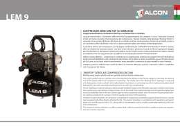
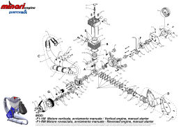
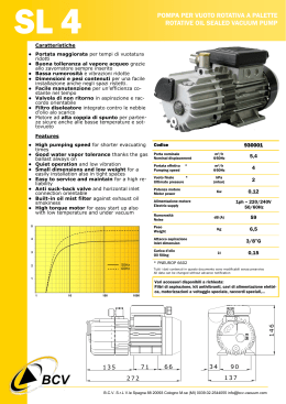
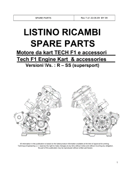
MOTOGENERATORE - MOTOSALDATRICE
ENGINE DRIVEN WELDER - GENERATING SET
MPM 12/400 SS/KA
MANUALE D’ISTRUZIONE
OWNERS MANUAL
MI496-01-00-00
Novembre 2006
Motosaldatrice - Engine Driven Welder MPM 12/400 SS/KA
INDICE / TABLE OF CONTENTS
1.
NORME GENERALI DI IMPIEGO / GENERAL USE INSTRUCTIONS ............................................................................3
1.1 MESSA IN SERVIZIO / CAUTION.......................................................................................................................................3
1.2 RODAGGIO / RUNNING IN .................................................................................................................................................3
1.3 AVVIAMENTO E FUNZIONAMENTO / STARTING AND WORKING ...........................................................................3
1.4 USI PROIBITI / FORBIDDEN USE.......................................................................................................................................3
1.5 MANUTENZIONE E PULIZIA / SERVICE AND CLEANING ...........................................................................................4
1.6 TARATURE E REGOLAZIONI / ADJUSTMENT AND REGULATIONS..........................................................................4
1.7 FERMO TEMPORANEO / TEMPORARY STANDSTILL ...................................................................................................4
1.8 DEMOLIZIONE / SCRAPPING.............................................................................................................................................4
2. CARATTERISTICHE TECNICHE / TECHNICAL SPECIFICATIONS..............................................................................5
2.1 SALDATURA C.C. / D.C. WELDING...................................................................................................................................5
2.2 GENERATORE / GENERATOR............................................................................................................................................5
2.3 MOTORE / ENGINE ..............................................................................................................................................................5
2.4 CARATTERISTICHE GENERALI / GENERAL FEATURES..............................................................................................6
3. DESCRIZIONE DEI COMANDI / CONTROLS DESCRIPTION ..........................................................................................7
3.1 PANNELLO FRONTALE / FRONT PANEL.........................................................................................................................7
3.2 DESCRIZIONE DEI COMANDI DEL PANNELLO FRONTALE / DESCRIPTION OF THE FRONT PANEL
CONTROLS.......................................................................................................................................................................................7
4. DAS : DISPOSITIVO ARRESTO AUTOMATICO PER PROTEZIONE MOTORE / DAS : AUTOMATIC STOP
DEVICE FOR ENGINE PROTECTION DESCRIPTION.......................................................................................................9
5. ISTRUZIONE PER L’USO / OPERATING INSTRUCTIONS ...............................................................................................9
5.1 MESSA A TERRA / EARTH CONNECTION .......................................................................................................................9
5.2 AVVIAMENTO DEL MOTORE / STARTING .....................................................................................................................9
5.3 IMPIEGO DEL GRUPPO COME MOTOSALDATRICE / USE OF MACHINE AS WELDER ........................................10
5.4 IMPIEGO DEL GRUPPO COME MOTOGENERATORE / USE OF MACHINE AS GENERATING SET .....................10
5.5 ARRESTO DEL GRUPPO / STOPPING THE ENGINE .....................................................................................................11
5.6 AVVERTENZE E CONSIGLI UTILI / WARNING ............................................................................................................11
5.7 TRASPORTO, STOCCAGGIO, SOLLEVAMENTO E MOVIMENTAZIONE / TRANSPORT, STORAGE, LIFTING
AND HANDLING ...........................................................................................................................................................................11
5.7.1
TRASPORTO, STOCCAGGIO / TRANSPORT, STORAGE....................................................................................11
5.7.2
SOLLEVAMENTO E MOVIMENTAZIONE DELLA MACCHINA / LIFTING AND HANDLING .....................12
5.7.3
SOLLEVAMENTO E MOVIMENTAZIONE CON GRU / LIFTING AND HANDLING WITH CRANE .............12
5.7.4
SOLLEVAMENTO E MOVIMENTAZIONE CON SOLLEVATORE A FORCHE / LIFTING AND HANDLING
WITH FORKLIFT TRUCK........................................................................................................................................................12
5.8 CAUSE DI SCARSO RENDIMENTO DEL MOTORE / CAUSES OF ENGINE POOR PERFORMANCE .....................14
6. RICAMBI / PARTS LIST ..........................................................................................................................................................21
6.1 PARTI STATORE - STATOR PARTS.................................................................................................................................21
6.2 FRONTALE (APPARECCHIATURE ELETTRICHE) - FRONTAL (ELECTRIC EQUIPMENT) ....................................23
6.3 PARTI LAMIERA - SHEET PARTS....................................................................................................................................26
7. ACCESSORI A RICHIESTA / ACCESSORIES ON REQUEST ..........................................................................................29
7.1 GRT2WSSKA- Gruppo Due Ruote Pneumatiche E Timone Per Traino Lento / GRT2WSSKA- Two Wheels Side Trailer
With Towing Bar .............................................................................................................................................................................29
7.2 RICAMBI GRT2WSSKA - GRT2WSSKA SPARE PARTS LIST.......................................................................................29
8. ACCESSORI A RICHIESTA / ACCESSORIES ON REQUEST ..........................................................................................30
8.1 Comando A Distanza Completo Di Cavo Per La Regolazione Della Corrente Di Saldatura (RC370) / Remote Control
(RC370)............................................................................................................................................................................................30
8.2 RICAMBI RC370 - RC370 SPARE PARTS LIST ...............................................................................................................30
9. SCHEMA ELETTRICO (VERSIONE BASE) / WIRING DIAGRAM (STANDARD VERSION).....................................31
10. SIMBOLI/SYMBOLS ................................................................................................................................................................32
11. CENTRI ASSISTENZA ITALIA / ITALIAN SERVICES CENTERS ..................................................................................33
12. CENTRI ASSISTENZA EUROPA / EUROPEAN SERVICES CENTERS ..........................................................................34
13. GARANZIA / WARRANTY......................................................................................................................................................35
14. GARANZIA MOTORE E RICAMBISTICA / ENGINE WARRANTY AND SPARE PARTS ..........................................35
14.1
INTRODUZIONE / INTRODUCTION ...........................................................................................................................35
14.2
GARANZIA MOTORE / ENGINE WARRANTY..........................................................................................................35
14.3
RICAMBI / SPARE PARTS ............................................................................................................................................35
2
MI496-01-00-00
Novembre 2006
Motosaldatrice - Engine Driven Welder MPM 12/400 SS/KA
1. NORME GENERALI DI IMPIEGO / GENERAL USE INSTRUCTIONS
Leggere attentamente le istruzioni d’uso; operare secondo le prescrizioni vigenti
nel paese di utilizzo.
1.1
Read the instructions carefully; proceed according to the regulations in use in
the country where the machine will operate.
MESSA IN SERVIZIO / CAUTION
Attenzione: il gruppo è fornito SENZA olio motore. Provvedere al rifornimento
con olio multigrado “10 W 40” indicato per temperature da - 20° C ad oltre 40°
C nella quantità indicata nelle specifiche motore indicate dalle
CARATTERISTICHE TECNICHE.
Attenzione: se la vostra macchina è raffreddata ad acqua (vedere nelle
CARATTERISTICHE TECNICHE del motore) provvedere al rifornimento del
circuito motore - radiatore con una soluzione di 50% acqua e 50% liquido
antigelo nella quantità indicata dalle specifiche motore.
Attenzione: il gruppo è fornito con batteria scarica e priva di acido. Provvedere
al suo riempimento utilizzando acido solforico in soluzione con concentrazione
30% - 40% fino alla copertura degli elementi. Durante questa operazione si
consiglia l’uso di guanti; il contatto accidentale con la soluzione di acido
solforico dovrà essere lavato immediatamente con acqua fredda e se necessario si
dovrà consultare il medico
Attenzione: non togliere i cavi della batteria quando la macchina è in moto, vi è
il rischio di danneggiare il corretto funzionamento della macchina.
Attenzione: PRIMA DI AVVIARE LA MACCHINA il centro-stella, o il punto
degli avvolgimenti che ne svolge la funzione, DEVE essere collegato a terra
rigidamente (senza interruttori o altri dispositivi che possano interrompere il
collegamento elettrico) mediante il morsetto adibito a questo scopo che è messo a
disposizione sulla struttura della macchina ed è identificato con il simbolo:
Be careful: the generating set or the welder is furnished WITHOUT lube oil.
Provide the machine with “10 W 40” multigrade oil indicated for temperatures
from - 20° C to 40° C in the quantity indicated in the engine SPECIFICATION
section.
Be careful: if the machine is fitted with a water cooled engine fill the radiator
circuit with a solution made up by 50% water and 50% antifreeze liquid inthe
quantity indicated i the engine SPECIFICATION section.
Attenzione: durante i normali trasferimenti si considerino le istruzioni riportate
nella sezione MOVIMENTAZIONE E TRASPORTO prestando attenzione nel
limitare eccessive inclinazioni della macchina re possono causare la fuoriuscita
di acidi della batteria.
Be carefull: for normal transportation, follow the instructions as specified in
the TRASPORTATION section. Make sure that the machine doesn’t overturn
in order to avoid spill of acids from the battery.
1.2
Be careful: the generating set is furnished with flat battery and without acid.
Fill it using sulphuric acid in a 30% - 40% concentrated solution up to the
complete covering of the elements. During this operation, we suggest the
operator to use the gloves; the accidental contact with the sulphuric acid
solution must be washed up immediately with cold water and, if necessari, a
doctor must be consulted.
Be carefull: don’t disconnect battery cables when the engine runs. This coud
result in serious damages to the machine.
Be carefull: BEFORE OPERATING THE MACHINE the neutral, or the
equivalen winding point, MUST be connected effectively to the earth (without
any switch or other device that may interrupt the electric connection) from the
earth clamp available on the machine, and identified by the symbol:
RODAGGIO / RUNNING IN
For the first 50 hours of operation of the machine do not employ more than
70% of the maximum power indicated in the technical specifications. In this
way, a proper engine running in is guaranteed.
Per le prime 50 ore di funzionamento della macchina, per consentire un buon
rodaggio del motore, non prelevare oltre il 70% della potenza massima indicata
nelle specifiche tecniche.
1.3
AVVIAMENTO E FUNZIONAMENTO / STARTING AND WORKING
Effettuare la messa a terra della macchina (vedi ISTRUZIONE PER L’USO).
Se il modello di macchina NON è dotato di interruttore differenziale la presa
disponibile è da utilizzarsi ESCLUSIVAMENTE per effettuare un collegamento
sicuro ad un quadro di distribuzione dotato di tutte le protezioni previste dalle
leggi vigenti
Verificare che i cavi del vostro utilizzatore siano in perfetta efficienza.
Assicurarsi che tutti gli interruttori, collegati e regolazioni siano nella posizione
prevista per l’avviamento (vedi ISTRUZIONE PER L’USO E DESCRIZIONE
DEI COMANDI).
Operare in ambiente ben ventilato preoccupandosi che i gas di scarico ed
eventuali fumi di saldatura (nel caso di motosaldatrici) non ristagnano
nell’ambiente di lavoro; tenere la macchina lontano da muri o altri ostacoli per
avvitare ricicli d’aria o di gas che ne provocherebbero il surriscaldamento. Nel
caso si dovesse operare in locali chiusi, utilizzare degli aspiratori per garantire un
corretto ricambio d’aria.
Durante la saldatura proteggere gli occhi ed il corpo con guanti, maschere e tute
adeguate (nel caso di motosaldatrice).
I rifornimenti di carburante non devono essere eseguiti fumando o in presenza di
fiamme libere e devono essere effettuati con motore spento.
Non riempire al massimo il serbatoio e pulire eventuali fuori uscite di carburante.
Make the earth connection (see the USE INSTRUCTIONS).
If the machine model IS NOT equipped with a earth leakege circuit breaker the
available socket is intended ONLY for connecting the machine to a switch
board equipped with all protection devices imposed by current law regulations.
Check the perfect state and efficiecy of the cables.
Make sure that all the switches, electric connections and regulations are inthe
right position for the starting (see USE INSTRUCTIONS and CONTROL
PANELS DESCRIPTIONS).
While welding, eyes and body must be protected by gloves, maskes Use the
machine in well ventilated places, taking care that the exhaust gas and the
welding smokes eventually produced (where welders are used) do not stagnate.
Keep the machine away from walls or other kind of obstacles i order to avoid
air or gas recycling. If the machine is employed in closed places, use aspirators
in order to guarantee a proper air recycling.
While welding, eyes and body must be potected by gloves, maskes and proper
clothes.
The fuel refill must not be made while smoking or close to flames. This
operation must be done when the engine is switched off.
Do not fill the tank at its maximum level and clean up the fuel eventually
overflowed.
Check daily if there is loss of fuel or lubrificating oil on the ducts or on the
engine.
For machines provided zith liftable canopy insert the foreseen security sistems
in order to avoid injures caused by an unexpected closure.
Controllare quotidianamente che non vi siano perdite di combustibile o di
lubrificanti lungo le canalizzazioni o sul motore.
Nelle macchine dotate di cofanature apribili assicurarsi di inserire i dispositivi di
bloccaggio previsti per evitare incidenti dovuti alla chiusura accidentale
1.4
USI PROIBITI / FORBIDDEN USE
Non collegare la macchina alla rete elettrica commerciale.
Non operare vicino a materiale infiammabile o in presenza di gas e vapori
esplosivi
Non operare in luoghi ristretti o poco aerati.
Non operare senza le protezioni previste nella loro posizione e nelle perfette
condizioni.
Non toccare le parti della marmitta e le parti del motore ad essa vicine.
Do not connect the machine to the commercial electric network.
Do not work close to inflammable materials or where there are explosive gas
and vapours.
Do not work in narrow and badly ventilated places.
Do not work without using the protections placed in their proper positions and
in perfect conditions.
Do not touch the exhaust muffler and the parts of the engine next to it.
3
MI496-01-00-00
Novembre 2006
Motosaldatrice - Engine Driven Welder MPM 12/400 SS/KA
Non eseguire interventi di manutenzione a motore avviato.
Ogni intervento sulle parti elettriche deve essere effettuato a motore spento e da
personale specializzato.
Tenersi lontano da parti in movimento e non avvicinarsi con indumenti liberi o
troppo lunghi.
1.5
Do not make service operations while the engine is running.
Any service made on the electric parts must be done when the engine is
stopped and by specialized technicians.
Keep away from the moving parts of the engine while working and do not
approach the machine with free and too long clothes.
MANUTENZIONE E PULIZIA / SERVICE AND CLEANING
We suggest a frequent cleaning of the machine since the presence of dirt can
compromise the efficiency of the machine. The frequency of this operation
tightly depends on the place where the machine is used. We advise, anyway. to
pay special care to the service of:
OIL LEVEL, OIL FILTER, AIR FILTER, COOLING LIQUID LEVEL,
COOLING LIQUID LEVEL, HEAT EXCHANGER, VENTILATION DUCTS
AND INTAKES, BATTERY
Consult the ENGINE USE AND SERVICE manual and the SPECIFICATION
section to know how and when it is useful to do it. The extraordinary service
operations not mentioned hereabove require the aid of specialized technicians
(see the assistance centre list).
E’ consigliata una periodica pulizia della macchina onde evitare depositi di
sporcizia che ne possono compromettere l’efficienza.
La frequenza di tale operazione è valutabile in funzione della zona d’impiego, si
consiglia comunque di prestare particolare attenzione alla manutenzione di:
LIVELLO OLIO, FILTRO OLIO, FILTRO ARIA, FILTRI CARBURANTE,
LIVELLO ACQUA RADIATORE, SCAMBIATORI DI CALORE.
Per le modalità e la frequenza consultare il MANUALE d’USO E
MANUTENZIONE del motore e le CARATTERISTICHE TECNICHE. Le
operazioni di manutenzione straordinaria che esulano da quelle citate,
necessitano dell’intervento di personale specializzato (vedere l’elenco dei centri
di assistenza).
1.6
TARATURE E REGOLAZIONI / ADJUSTMENT AND REGULATIONS
All the necessary controls are located on the main control panel and they are
properly explained in the section FRONT PANEL DESCRIPTIONS.
We advise the operator against tempering with the engine or the electric part if
not specialized.
Be careful: eventual modifications of the normal parameters originally
foressen, can compromise the reliability of the machine.
I comandi per le regolazioni necessarie all’uso sono installati sul pannello di
comando e descritti all’interno della DESCRIZIONE DEI COMANDI.
E’ pertanto sconsigliato l’intervento della macchina da parte di personale non
specializzato.
Attenzione: eventuali tarature non corrette dei normali parametri previsti
all’origine possono compromettere l’affidabilità stessa della macchina.
1.7
FERMO TEMPORANEO / TEMPORARY STANDSTILL
If the machine has to be stopped for a long period (more than one year), we
suggest to leave the motor oil and the fuel in and the water in the radiator in
order to avoid oxydizing effects.
When the machine turns to work again, the liquids must be replaced, the
battery must be charged; the belts and their statem the pipes, the rubber hoses
and their resistance must be checked and a visual inspections of the electric
connections must be done.
Qualora si debba fermare la macchina per un lungo periodo di tempo (maggiore
di un anno) è consigliato lasciare i liquidi quali: olio motore, acqua radiatore e
carburante, onde evitare ossidazioni.
Alla ripresa in esercizio si dovranno: sostituire i liquidi, ripristinare la batteria,
ispezionare le cinghie e il loro stato, ispezionare le tubature e i giunti in gomma e
la loro tenuta e ispezionare visivamente i cablaggi elettrici.
1.8
DEMOLIZIONE / SCRAPPING
In order to preserve the environnement, it is advised to dispose of the oil, the
fuel and the bettery that will be destroyed in proper places and ccording to the
current laws. For the complete range of the materialsm see the list below:
Al fine di salvaguardare l’ambiente naturale è opportuno provvedere alla raccolta
dell’olio, del combustibile e della batteria che dovranno essere smaltiti nelle sedi
e nelle modalità conformi alle leggi vigenti.
Per l’elenco completo dei materiali si veda la scheda allegata:
MATERIALI FERROSI:
acciaio, ghisa, alluminio, rame, ottone compongono strutture portanti , motore,
alternatore, trasformatori
MATERIALI PLASTICI:
gomma, bakelite, epovit, lexan compongono strumentazione, manicotti motore,
morsettiere e connettori, serbatoi, tappi, ruote, antivibranti, contenitori
condensatori, ventole, cinghie, filtri e guaine.
MATERIALI ELETTRONICI:
componenti vari, diodi, resistenze, semiconduttori, pannelli elettronici.
MATERIALI VARI:
lana di roccia, rivestimenti fonoassorbenti.
MATERIALI LIQUIDI:
gasolio o benzina, liquidi antigelo, acido batteria.
FERROUS MATERIALS:
steel, cast iron, aluminium, copper, brass are udes in the bearing structure of
engine, alternator, transformers, etc.
PLASTIC MATERIALS:
rubber, bakelite, epovit, lexan are used for the instruments, engine pipes,
junction boxes and connectors, fuel tank, fuel cap, wheels, antivibration
damper, condenser housing, fans, belts, filters and hoses.
ELECTRONIC MATERIALS:
various components, diodes, resistances, electronic panels.
VARIOUS MATERIALS:
rock woll, sound proofing materials.
LIQUIDS:
fuel, gasoline, cooling liquids, battery acid.
4
MI496-01-00-00
Novembre 2006
Motosaldatrice - Engine Driven Welder MPM 12/400 SS/KA
2. CARATTERISTICHE TECNICHE / TECHNICAL SPECIFICATIONS
2.1 SALDATURA C.C. / D.C. WELDING
Saldatura con intermittenza del 35%
370 A - 35 V
Rated output at 35% duty cycle
Saldatura con intermittenza del 60%
350 A - 34 V
Rated output at 60% duty cycle
Regolazione della corrente
30 ÷ 170 A / 30 ÷ 370 A Range of continuous control
Tensione d’innesco
70 V
Striking voltage
Diametro max elettrodo saldabile
6 mm
Electrodes diameter
2.2 GENERATORE / GENERATOR
Tipo
Asincrono /
Asynchronous
Type
Potenza trifase
12 kVA 415 V
Three phase power
Potenza monofase
8 kVA 240 V
Single phase power
Potenza monofase
6 kVA 110 V
Single phase power
Frequenza
Cos ϕ
50 Hz
0,8
Classe di isolamento
F
Grado di protezione
IP 23
Frequency
Cos ϕ
Insulation class
Mechanical protection
2.3 MOTORE / ENGINE
Tipo motore
Kubota D1105-E
Numero cilindri
3
Make/Type
Number of cylinders
Cilindrata
1123 cm3
Displacement
Potenza
29,5 HP
Power
Velocità
3000 r.p.m.
Raffreddamento
Carburante
Capacità coppa olio
Avviamento
Consumo specifico
Acqua - Water
Diesel
5,1
Elettrico - Electric
265 gr/kWh
5
Engine speed
Cooling
Fuel
Oil sump capacity
Starting system
Specific fuel consumption
MI496-01-00-00
Novembre 2006
Motosaldatrice - Engine Driven Welder MPM 12/400 SS/KA
2.4 CARATTERISTICHE GENERALI / GENERAL FEATURES
Potenza acustica
Batteria
Capacità serbatoio carburante
Autonomia carico 50% interm. 60%
Dimensioni (Lu. x La. x H.)
Peso
94 Lwa
12 V - 44 Ah
60 l
29 h 30’ ~
1720x800x970 mm
575 kg
6
Noise level
Battery
Fuel tank capacity
Average operating hours
Dimensions (L. x W. x H.)
Weight
MI496-01-00-00
Novembre 2006
Motosaldatrice - Engine Driven Welder MPM 12/400 SS/KA
3. DESCRIZIONE DEI COMANDI / CONTROLS DESCRIPTION
3.1 PANNELLO FRONTALE / FRONT PANEL
3.2 DESCRIZIONE DEI COMANDI DEL PANNELLO FRONTALE / DESCRIPTION OF
THE FRONT PANEL CONTROLS
1
Chiave di avviamento
Starting key
2
Voltmetro di tensione monofase
Single phase voltmeter
3
Contaore di funzionamento
Hour-meter
4
Indicatore luminoso pressione olio
Oil pressure lamp
7
MI496-01-00-00
Novembre 2006
Motosaldatrice - Engine Driven Welder MPM 12/400 SS/KA
5
Indicatore luminoso carica batteria
Battery charge lamp
6
Indicatore luminoso temperatura acqua
Water temperature lamp
7
Indicatore luminoso preriscaldo candelette
Glow plug lamp
8
Indicatore del livello carburante
Fuel gauge - Monitor fuel level
9
Spia riserva carburante
Low fuel level signal lamp
10
Deviatore di accelerazione Auto/Max
Auto/Max throttle switch
11
Deviatore dei comandi di regolazione della Remote control switch
corrente di saldatura
12
Calibratore della corrente di saldatura
13
Deviatore di regolazione della corrente di 30 ÷ 170 / 30 ÷370 A welding current
saldatura 30 ÷ 170 / 30 ÷370 A
control switch
14
Manopola di variazione penetrazione d’arco
Arc force regulator
15
Deviatore Basico/Cellulosico
Basic/Cellulosic switch
16
Connettore del calibratore di saldatura del Remote control jack
comando a distanza
17
Presa di corrente monofase 110 V 32 A
110 V 32 A single phase outlet
18
Presa di corrente monofase 240 V 32 A
240 V 32 A single phase outlet
19
Presa di corrente trifase 415 V 16 A
415 V 16 A three phase outlet
20
Interruttore termico bipolare
protezione presa 110 V monofase
32
A 32 A 2 poles circuit breaker controls
110 V single phase power source
21
Interruttore termico unipolare
protezione presa 240 V monofase
25
A 25 A 1 pole circuit breaker controls
240 V single phase power source
22
Numero di serie della macchina
Serial number
23
Interruttore differenziale 25 A
25 A earth leakage circuit breaker
24
Deviatore invertitore di polarità (a richiesta)
Polarity switch (on request)
25
Presa di saldatura : Negativo
Welding receptacle: Negative output
welding connection
26
Presa di saldatura : Negativo di scriccatura Welding receptacle: Negative output
(Gouging only)
welding connection (Gouging only)
27
Presa di saldatura : Positivo
28
Morsetto di massa per il collegamento a terra Earth clamp connection
Welding current control
Welding receptacle:
welding connection
8
Positive
output
MI496-01-00-00
Novembre 2006
Motosaldatrice - Engine Driven Welder MPM 12/400 SS/KA
4. DAS : DISPOSITIVO ARRESTO AUTOMATICO PER PROTEZIONE
MOTORE / DAS : AUTOMATIC STOP DEVICE FOR ENGINE
PROTECTION DESCRIPTION
Questo dispositivo viene montato a bordo
macchina. Nel caso in cui durante le fasi di
lavoro si verificassero delle anomalie, come:
bassa pressione olio, alta temperatura acqua,
non carica della batteria, riserva carburante,
provvede allo spegnimento del motore
preservando così da possibili danni. Sul
pannello luminoso rimarrà accesa la spia
corrispondente alla causa per cui è stato
arrestato il motore. Ad inconveniente eliminato
una nuova richiesta di avviamento azzererà la
memoria del dispositivo.
The DAS Engine Protection Device checks
for faulty condition at the starting of the
engine. When the low oil pressure, high water
temperature, no battery charge, low fuel
level, conditions accours the DAS stop the
engine and lights the corresponding lamp on
the control panel of the generating set. When
the faulty condition has been removed the
generating set return to its normal operations.
5. ISTRUZIONE PER L’USO / OPERATING INSTRUCTIONS
5.1 MESSA A TERRA / EARTH CONNECTION
Effettuare la messa a terra del gruppo tramite il
morsetto 28.
Connect the unit to the earth, means of the 28
clamp.
5.2 AVVIAMENTO DEL MOTORE / STARTING
A rifornimento di olio e carburante avvenuto
procedere come segue:
After filling up with oil and fuel, proceed as
follow:
Check water level.
Controllare che l’acqua nel radiatore sia al
giusto livello.
Controllare che il deviatore 10 sia in posizione
AUTO.
Check that throttle switch 10 is at AUTO
position
Posizionare la chiave di avviamento 1 sul
primo scatto per consentire il preriscaldo
candelette, spia 7 accesa. Allo spegnimento
della spia 7, avviare il motore portando la
chiave 1 a fondo corsa in senso orario.
Position the starting key 1 on the first step to
avoid the glow plugs preliminary heating,
warning light 7. When warning light 7 is off,
start the engine moving key 1 completely
clockwise.
Nota: Se il motore non si avvia attendere circa
10 secondi e ripetere l’operazione, portando
prima la chiave in posizione OFF.
Note: If the engine falls to start, turn the
switch to the OFF position and wait 10
seconds before operating the starter again.
Lasciare il motore a funzionare per circa 10
minuti in modo da consentire un regolare
riscaldamento.
Let the engine to run for about 10 minutes to
warm it up.
9
MI496-01-00-00
Novembre 2006
Motosaldatrice - Engine Driven Welder MPM 12/400 SS/KA
5.3 IMPIEGO DEL GRUPPO COME MOTOSALDATRICE / USE OF MACHINE AS
WELDER
Innestare le spine dei cavi di saldatura sulle
relative prese 26 (negativo per scriccatura:
gouging only), 25 (negativo), 27 (positivo).
Insert welding cable plugs into relevant
sockets 26 (negative for gouging only), 25
(negative), 27 (positive).
La regolazione della corrente di saldatura si
ottiene manovrando il calibratore 12.
La numerazione della scala riportata sul
frontale è approssimativa.
La regolazione di penetrazione d’arco (Arc
Force) si ottiene manovrando il calibratore 14.
Setting of the welding current is obtained by
turning the potentiometer 12.
The scale surrounding the control represents
approximate actual amperage values.
Setting of Arc Force control is obtained by
turning the potentiometer 14.
Se si impiega il comando a distanza della
corrente di saldatura (fornito solo su richiesta)
portare il deviatore 11 in posizione I (ON) e
collegare il cavetto del calibratore con la presa
16 mediante il corrispondente raccordo ad
innesto.
Setting of the welding current may be
obtained at distance with a special remote
control device (supplied on request). When
operaring with remote control put switch 11
to position I (ON) and current the cable of the
remote control unit to outlet 16.
Per elettrodi basici e cellulosici la PINZA va
collegata al morsetto positivo.
For basic and cellulosic electrodes the
welding PLIERS have to be connected to the
positive terminal.
Per elettrodi rutili ed acidi la PINZA va
collegata al morsetto negativo.
For rutile and acid electrodes the welding
PLIERS have to be connected to the negative
terminal.
5.4 IMPIEGO DEL GRUPPO COME MOTOGENERATORE / USE OF MACHINE AS
GENERATING SET
Interruttore differenziale.
La macchina è dotata di un interruttore
differenziale in grado di assicurare la
protezione dell’utente in caso di contatto
accidentale con parti in tensione o di
malfunzionamento del sistema di isolamento
dei dispositivi collegati.
Earth Leakage Circuit Breaker.
The product is equipped with an Earth
Leakage Circuit Breaker (ELCB) which
guarantees user protection against electric
shocks due to unwanted contect with live
parts of the circuit or insulation fault.
Attenzione!
Per consentire il corretto funzionamento
dell’interruttore differenziale la macchina deve
essere collegata a terra. L’impianto di terra
deve essere conforme a quanto prescritto dalle
norme CEI 64-8.
Warning!
In order to guarantee ELCB proper operation,
the product must be earthed. Earthing
connection must conform to IEC 364
standard.
10
MI496-01-00-00
Novembre 2006
Motosaldatrice - Engine Driven Welder MPM 12/400 SS/KA
Collegarsi al generatore utilizzando spine
adatte alle prese e cavi in ottime condizioni.
Connect up to the generator using jacks that
fit the outlets and cables in excellent
condition.
Il voltmetro 2 indica la tensione a vuoto
(circa 245 V sia che si debba prelevare corrente
trifase che monofase).
The voltmeter 2 indicates the free voltage
(around 245 V, whether the current to be
drawn is three or single phase).
5.5 ARRESTO DEL GRUPPO / STOPPING THE ENGINE
Togliere i carichi inseriti.
Disconnet the utilizer.
Portare la chiave avviamento 1 in posizione
“STOP”.
Turn the start key switch 1 at “STOP”
position
5.6 AVVERTENZE E CONSIGLI UTILI / WARNING
É importante conservare il motore in perfette
condizioni, si consiglia perciò la rigorosa
osservanza delle norme di manutenzione
riportate nel catalogo “Uso e manutenzione”
del motore onde evitare inconvenienti ed una
conseguente perdita di potenza del generatore.
In order to preserve the engine performance
Gen Set strongly suggests to follow the
maintenance operations and the maintenance
schedule reported in the engine manufacturer
“Use and maintenance” user manual. Poor
maintenance could result in a shorter period
of operation and in performance decrease.
5.7 TRASPORTO, STOCCAGGIO, SOLLEVAMENTO E MOVIMENTAZIONE /
TRANSPORT, STORAGE, LIFTING AND HANDLING
5.7.1 TRASPORTO, STOCCAGGIO / TRANSPORT, STORAGE
IMBALLO: viene fornito direttamente dalla
supplied
directly
by
GEN.SET. The total weight of the packed
generator is given in page 3. It is strictly
prohibited to pollute the environment with
the packaging
PACKAGING:
ditta GEN.SET. Il peso totale del gruppo
elettrogeno imballato si trova a pag.3.
E’
assolutamente
vietato
disperdere
nell’ambiente gli imballi
TARSPORTO: Durante il trasporto, il gruppo
elettrogeno,(con o senza imballo) deve essere
protetto dagli agenti atmosferici, esso non deve
essere capovolto e deve essere preservato da
qualsiasi urto. Il gruppo elettrogeno, deve
essere trasportato privo di carburante per
evitare perdite lungo il percorso.
TRANSPORT: During transport the generator
STOCCAGGIO: il gruppo elettrogeno deve
horizontal position and away
atmospheric agents and humidity.
(with or without packaging) must be protected
against atmospheric agents, it must not be
turned down and must be protected against
knocks. The generator must be transported
without fuel to prevent leaks during travel.
STORAGE: the generator must be stored in
essere immagazzinato in posizione orizzontzale
ed al riparo da agenti atmosferici e
dall’umidita’.
11
MI496-01-00-00
Novembre 2006
from
Motosaldatrice - Engine Driven Welder MPM 12/400 SS/KA
5.7.2 SOLLEVAMENTO E MOVIMENTAZIONE DELLA MACCHINA / LIFTING AND
HANDLING
ATTENZIONE ! Tutte le operazioni di
INFORMATION ! All the lifting operations
sollevamento vanno effettuate da personale
specializzato per questo tipo di lavoro, come
carrellisti, gruisti, imbracatori. Considerare
l’operatore come il responsabile nell’uso
della corretta tecnica di imbracaggio e
sollevamento macchina.
must be carried out by personnel
specialised in this type of work, such as
truck drivers, crane drivers, slingers. The
operator is considered responsible for
using the correct machine slinging and
lifting technique.
5.7.3 SOLLEVAMENTO E MOVIMENTAZIONE CON GRU / LIFTING AND HANDLING
WITH CRANE
Occorre che la macchina venga sollevata e
movimentata come nei sistemi indicati in figura
a pag. 13. Verificare che i cavi o le catene di
sollevamento siano omologate e di sufficiente
portata, come pure la lunghezza minima dei
cavi. Utilizzare sempre gli occhielli forniti
dalla casa e sempre segnalati da apposito
pittogramma.
The machine must be lifted and handled with
the systems indicated in the picture to page
13. Check that the hoisting cables or chains
are homologated and of sufficient capacity,
and also check the minimum cable length.
Always use the eyebolts provided by the
manufacturer and always marked with a
pictogram.
NEL SOLLEVARE IL GENERATORE USARE
SEMPRE QUESTE PRECAUZIONI:
ALWAYS TAKE THESE PRECAUTIONS
WHEN LIFTING THE GENERATOR:
Non oscillare i carichi sospesi
Do not swing suspended loads
Non lasciare mai incustodito il carico
Never leave the load unattended
Molto lentamente appoggiare il generatore al
terreno
Lower the generator to the ground very
slowly
Mantenersi sempre a distanza di sicurezza.
Always maintain the safety distance
5.7.4 SOLLEVAMENTO E MOVIMENTAZIONE CON SOLLEVATORE A FORCHE /
LIFTING AND HANDLING WITH FORKLIFT TRUCK
Utilizzare un carrello sollevatore a forche
larghe, di portata adeguata e sollevare in
posizione baricentrica (che corrisponde circa al
centro del suo volume geometrico).
Use a forklift truck with wide forks and of
adequate capacity and lift in a barycentric
position (which corresponds to about the
centre of its geometrical volume).
Non è possibile sollevare la versione carrellata
con il sollevatore a forche.
The trailer version cannot be lifted with a
forklift.
12
MI496-01-00-00
Novembre 2006
Motosaldatrice - Engine Driven Welder MPM 12/400 SS/KA
La struttura di sollevamento è progettata per
mantenere in sospensione il gruppo elettrogeno
il tempo strettamente necessario alla
movimentazione del gruppo stesso
13
NON PARCHEGGIARE IL GRUPPO IN
SOSPENSIONE !
MI496-01-00-00
Novembre 2006
Motosaldatrice - Engine Driven Welder MPM 12/400 SS/KA
5.8 CAUSE DI SCARSO RENDIMENTO DEL MOTORE / CAUSES OF ENGINE POOR
PERFORMANCE
PULIZIA TAZZA FILTRO CARBURANTE
CLEANING THE FUEL FILTER POT
Ogni 100 ore di funzionamento, pulire il filtro
del carburante. Operazione da eseguire in un
luogo pulito in modo da evitare intrusione di
polvere.
Every 100 hours of operation, clean the fuel
filter. And so on in a clean place to prevent
dust intrusion.
Operazioni:
• Chiudere il rubinetto della tazza del filtro
carburante (fig.1 n°1, posizione B).
• Rimuovere il tappo superiore e risciacquare
la parte interna con gasolio.
• Estrarre
l’elemento
(fig.1
n°2)
e
risciacquarlo con gasolio.
• Dopo la pulizia, reinstallare il filtro del
carburante, proteggendolo da polvere e
sporco.
• Spurgare la pompa di iniezione.
SOSTITUZIONE DELLA CARTUCCIA
DEL FILTRO DEL CARBURANTE
Operations:
• Close the fuel filter chock (fig.1, position
B).
• Remove the top cap, and rinse the inside
with diesel fuel.
• Take out the element (fig.1 n°2), and rinse
it with diesel fuel.
• After cleaning, reinstall the fuel filter,
keeping out of dust and dirt.
Sostituire la cartuccia del filtro del carburante
(fig.3 n°1) con una nuova ogni 400 ore circa di
funzionamento.
Replace the fuel filter cartridge with new one
every 400 operating hours or so.
Operazioni:
Operations:
• Applicare un leggero strato di gasolio sulla
guarnizione, quindi serrare a fondo con le
mani la cartuccia in posizione.
• Infine disaerare il sistema.
IMPORTANTE: La cartuccia del filtro del
carburante
deve
essere
sostituita
periodicamente
in modo da evitare che il
tuffante o il polverizzatore della pompa di
iniezione vengano prematuramente usurati a
causa della penetrazione di impurità nel
carburante.
OLIO DEL MOTORE
• Apply fuel oil thinly over the gasket and
tighten the cartridge into position handtight.
• Finally vent the air.
IMPORTANT: Replace the fuel filter
cartridge periodically to prevent wear of the
fuel injection pump plunger or the injection
nozzle due to dirt in the fuel.
ENGINE OIL
• CAUTELA: Per evitare lesioni personali,
accertarsi di spegnere il motore prima di
controllare il livello dell’olio e prima di
cambiare la cartuccia del filtro dell’olio.
• CAUTION: To avoid personal injury, be
sure to stop the engine before checking the
oil level, changing the oil and the oil filter
cartridge.
• NOTA: Non mancare di ispezionare il
motore collocandolo su un posto in piano.
Se collocato su un posto in pendenza, non è
• NOTE: Be sure to inspect the engine,
locating it on a horizontal place. If placed
on gradients, accurately, oil quantity may
• Air-bleed the injection pump.
FUEL
FILTER
CARTRIDGE
REPLACEMENT
14
MI496-01-00-00
Novembre 2006
Motosaldatrice - Engine Driven Welder MPM 12/400 SS/KA
possibile misurare accuratamente la quantità
dell’olio.
CONTROLLO
DEL
LIVELLO
E
RABBOCCO DELL’OLIO DEL MOTORE
Operazioni :
• Controllare il livello dell’olio del motore
prima dell’avviamento, oppure quando sono
passati più di 5 minuti dall’arresto.
• Disinserire l’indicatore del livello dell’olio
(fig.4 n°2), pulirlo bene strofinandolo e
reinserirlo.
not be measured.
CHECKING LEVEL AND ADDING
ENGINE OIL
Operations
• Check the engine oil level before starting
or more than five minutes after stopping.
• Detach the oil level gauge (fig.4 n°2), wipe
it clean and reinstall it.
• Estrarre di nuovo l’indicatore del livello
dell’olio e controllare il livello dell’olio.
• Take the oil level gauge out again, and
check the oil level.
• Se il livello dell’olio è troppo basso, togliere
il tappo dell’olio (fig.4 n°1) e aggiungere
olio fino a che raggiunge il livello prescritto
(fig.4 A).
• If the oil level is too low, remove the oil
filter plug (fig.4 n°1) and add new oil to
the prescribed level (fig.4 A).
• Aggiunto l’olio aspettare più di 5 minuti e
controllarne di nuovo il livello. Questo
tempo è necessario perché l’olio raggiunga
la coppa dell’olio.
• After adding oil, wait more than 5 minutes
and check the oil level again. It takes same
time for the oil to come down to the oil
pan.
CAMBIO DELL’OLIO MOTORE
CHANGING ENGINE OIL
• Cambiare olio dopo le prime 50 ore di
funzionamento iniziale, successivamente,
ogni 200 ore.
Change oil after the initial 50 hours of
operation and every 200 hours thereafter.
Operazioni :
Operations :
• Rimuovere il tappo di scarico dell’olio che
si trova sul lato destro del basamento, e
scaricare l’olio vecchio. Lo scarico dell’olio
è più facile e completo se viene eseguito
quando il motore è caldo.
• Remove the drain plug on the right side of
the frame and drain all the old oil. Drain
oil easier and completely while the engine
is hot.
• Aggiungere olio motore nuovo fino al livello
superiore dell’indicatore del livello dell’olio.
• Add new engine oil up to the upper limit of
the oil level gauge.
SOSTITUZIONE DELLA
DEL FILTRO DELL’OLIO
REPLACING
CARTRIDGE
CARTUCCIA
THE
OIL
FILTER
• CAUTELA : Per evitare lesioni personali :
cambiare la cartuccia del filtro dell’olio solo
a motore spento e lasciar raffreddare
sufficientemente il motore; l’olio può essere
molto caldo e ustionare.
• CAUTION : To avoid personal injury be
sure to stop the engine before changing the
oil filter cartridge and allow engine to cool
down sufficiently; oil can be hot and can
burn.
Operazioni :
Operations
• Sostituire la cartuccia del filtro dell’olio
• Replace the oil filter cartridge (fig.5 n°1)
15
MI496-01-00-00
Novembre 2006
Motosaldatrice - Engine Driven Welder MPM 12/400 SS/KA
(fig.5 n°1) ogni 200 ore di servizio.
• Estrarre la cartuccia del
servendosi di una chiave.
every 200 hours of operation.
usata
• Detach the old oil filter cartridge with a
filter wrench.
• Oliare leggermente la guarnizione per la
nuova cartuccia.
• Apply a film of oil to the gasket for the
new cartridge.
• Avvitare a mano la cartuccia. Quando la
guarnizione arriva a contatto della superficie
di tenuta, stringere la cartuccia quanto basta
e sempre a mano. Questo perché usando una
chiave la cartuccia verrebbe serrata troppo.
• Screw in the cartridge by hand. When the
gasket contacts the seal surface, tighten the
cartridge enough by hand. Because, if you
tight the cartridge with wrench, it will be
tightened too much.
• Dopo che la cartuccia è stata sostituita, di
solito il livello dell’olio si abbassa un p. Per
questo motivo, far girare il motore per un
po’ di tempo e controllare se ci sono perdite
di olio dalla guarnizione di tenuta prima di
controllare il livello dell’olio. Se necessario,
aggiungere dell’olio.
• After the new cartridge has been replaced,
the engine oil level normally decreases a
little. Thus, run the engine for a while and
check oil leaks through the seal before
checking the engine oil level. Add oil if
necessary.
• NOTA : Strofinare via completamente l’olio
appiccicato alla macchina.
• NOTE : Wipe off any oil sticking to the
machine completely.
RADIATORE
RADIATOR
• Il refrigerante, se rabboccato completamente
prima di mettere in marcia il motore, dura
una giornata di lavoro. Pertanto il livello del
refrigerante deve essere regolarmente
controllato prima di ogni messa in funzione.
Coolant will last for one day’s work if filled
all the way up before operation start. Make it
a rule to check the coolant level beforeevery
operation.
• AVVERTENZA : Per evitare lesioni
personali non rimuovere il tappo del
radiatore quando il motore è caldo. In
seguito, allentare leggermente il tappo fino
al fermo per scaricare l’eccesso di pressione,
quindi rimuoverlo completamente.
• WARNING : To avoid personal injury do
not remove the radiator cap when the
engine is hot. Then loosen cap slightly to
the stop to relieve any excess pressure
before removing cap completely.
CONTROLLO DEL LIVELLO
REFRIGERANTE,
AGGIUNTA
REFRIGERANTE
CHECKING COOLANT
ADDING COOLANT
filtro
DEL
DI
LEVEL
,
• Operazioni :
• Operations :
• Rimuovere il tappo del radiatore (fig.6 n° 1),
e verificare che il refrigerante raggiunga il
bocchettone di rifornimento.
• Remove the radiator cap (fig.6 n°1), and
check to see that coolant reaches the
supply port.
• Quando il livello del refrigerante si abbassa
a causa della evaporazione, aggiungere solo
acqua fino a raggiungere il livello di pieno.
• When the coolant level drops due to
evaporation, add water only up to the full
level.
• Controllare i due rubinetti di scarico; uno si
trova nella parte di basamento (fig. 7) e
• Check to see that two drain cocks; one is at
the crankcase side (fig. 7) and the other is
16
MI496-01-00-00
Novembre 2006
Motosaldatrice - Engine Driven Welder MPM 12/400 SS/KA
l’altro nella parte bassa del radiatore (fig. 8).
at the lower part of the radiator (fig. 8).
IMPORTANTE : Se occorre rimuovere il
tappo del radiatore, seguire le precauzioni
riportate sopra e riavvitarlo saldamente.
Dovesse esserci una perdita d’acqua, consultare
il concessionario KUBOTA.
IMPORTANT : If the radiator cap has to be
removed, follow the caution above and
securely retighten the cap. If water should be
leak, consult your local KUBOTA dealer.
CAMBIO LIQUIDO RAFFREDDAMENTO
CHANGING COOLANT
Operazioni :
Operations :
• Per scaricare il refrigerante, aprire sempre
entrambi i rubinetti di scarico e aprire
contemporaneamente il tappo del radiatore.
Lo scarico completo dell‘acqua è
impossibile se il tappo del radiatore viene
tenuto chiuso.
• To drain coolant, always open both drain
cocks and simultaneously open the radiator
cap as well. With the radiator cap kept
closed, a complete drain of water is
impossible.
• Rimuovere il tubo di traboccamento del
tappo a pressione del radiatore per scaricare
il serbatoio di riserva.
• Remove the overflow pipe of the radiator
pressure cap to drain the reserve tank.
FILTRO DELL’ARIA
AIR CLEANER
Se l’elemento del filtro dell’aria impiegato in
questo motore è del tipo secco, non deve mai
essere oliato
As the element of the air cleaner employed on
this engine is a dry type, never apply oil to it.
• In condizioni normali d’esercizio, la valvola
d’evacuazione (fig.9 n°4) deve essere aperta
una volta alla settimana oppure tutti i giorni
se viene usata in ambiente polveroso in
modo da rimuovere la polvere e le piccole
impurità.
• Open the evacuator valve (fig.9 n°4) once
a week under ordinary conditions-or daily
when used is in a dusty place-to get rid of
large particles of dust and dirt.
Operazioni :
Operations:
• Pulire l’interno del filtro dell’aria con un
panno o simili se esso fosse sporco o umido.
• Wipe the inside air cleaner clean with cloth
or the like if it is dirty or wet.
• Evitare di toccare l’elemento se non per
pulirlo.
• Avoid touching the element except when
cleaning.
• Se la polvere dovesse aderire all’elemento
rimuoverla mediante aria compressa
dall’interno verso l’esterno, ruotando
l’elemento. La pressione dell’aria compressa
deve essere inferiore a 686kPa (7kg/cm²,
99psi).
• When dry dust adheres to the element,
blow compressed air from the inside
turning the element. Pressure of
compressed air must be under 686kPa
(7kg/cm², 99psi).
17
MI496-01-00-00
Novembre 2006
Motosaldatrice - Engine Driven Welder MPM 12/400 SS/KA
• Se all’elemento dovesse aderire carbone
oppure olio, immergere l’elemento in un
bagno detergente per 30 minuti, quindi
sciacquarlo alcune volte con acqua pulita e
lasciarlo essiccare all’aria.
• When carbon or oil adheres to the element,
soak the element in detegent for 30
minutes then wash it several times in
water, rinse with clean water and dry it
naturally.
• Quando l’elemento è completamente
essiccato controllare con una torcia elettrica
che il suo interno non sia stato danneggiato
(seguendo le istruzioni sovrastampate sulla
targhetta dell’elemento).
• After element is fully dried, inspect inside
of the element with a light and check if it is
damaged or not. (referring to the
intructions on the label attached to the
element.).
• Sostituire l’elemento ogni anno oppure ogni
6 operazioni di pulizia.
• Replace the element every year or every
six cleanings.
IMPORTANTE : Accertarsi che la vite ad
alette (fig. 9 n°3) per l’elemento sia serrata a
fondo. Se questa è allentata, la polvere e lo
sporco potrebbero venire aspirati, logorando il
cilindro e l’anello di tenuta con una
conseguente diminuzione della resa del motore.
IMPORTANT : Make sure the wing bolt
(fig. 9 n°3) for the element is tight enough. If
it is loose, dust and dirt may be sucked,
wearing down the cylinder liner and piston
ring earlier and thereby resulting in poor
power output.
• VALVOLA D’EVACUATORE
• EVACUATOR VALVE
In condizioni normali d’esercizio, la valvola
d’evacuazione (fig.9 n°4) deve essere aperta
una volta alla settimana oppure tutti i giorni se
viene utilizzata in un ambiente polveroso in
modo da rimuovere la polvere e le piccole
impurità.
Open the evacuator valve once a week under
ordinary conditions-or (fig.9 n°4) daily when
used in a dusty place-to get rid of large
particles of dust and dirt.
18
MI496-01-00-00
Novembre 2006
Motosaldatrice - Engine Driven Welder MPM 12/400 SS/KA
1
2
3
4
5
6
19
MI496-01-00-00
Novembre 2006
Motosaldatrice - Engine Driven Welder MPM 12/400 SS/KA
7
8
9
20
MI496-01-00-00
Novembre 2006
Motosaldatrice - Engine Driven Welder MPM 12/400 SS/KA
6. RICAMBI / PARTS LIST
6.1 PARTI STATORE - STATOR PARTS
21
MI496-01-00-00
Novembre 2006
Motosaldatrice - Engine Driven Welder MPM 12/400 SS/KA
Numero Numero
Posizione Codice
Item N° Ordering
N°
1
21.974
2
21.368
3
21.253
4
21.254
5
14.339
6
18.488
7
903
8
0905
9
18.699
10
10.175
11
21.255
12
21.061
13
21.062
14
15
16
17
18
19
20
21
22
23
24
25
26
27
28
29
30
21.063
24.636
23.028
21.975
23.029
21.065
18.576
14.764
614
16.265
12.496
16.267
21.398
10.661
21.557
21.398
24.637
Descrizione
Denomination
Alternatore
Protezione alternatore
Convogliatore aria alternatore
Flangia attacco motore
Disco inox
Albero completo di rotore
Cuscinetto 6309-2RS 100-45-25
Anello seeger
Flangia porta cuscinetto
Ventola
Copriventola
Staffa sinistra per supporto trave di
sollevamento
Staffa destra per supporto trave di
sollevamento
Trave di sollevamento
Staffa per asta
Supporto elettromagnete
Elettromagnete
Molla
Lamiera separatrice alternatore
Pannelo elettronico GS9603/B
Trasformatore
Morsettiera 3 poli
Copristrumentazione
Perno (lungo) per molla
Copristrumentazione centrale
Perno per elettromagnete
Tirante per flange
Supporto filtro aria
Perno per elettromagnete
Asta fermo carenatura
Stator
Stator protection
Stator air conveyor
Engine connection flange
Flex plate
Shaft with rotor
6309-2RS 100-45-25 bearing
Seeger ring
Flange with bearing seat
Fan
Fan cover
Left plate for hook
22
Right plate for hook
Hook
Plate
Solenoid support
Solenoid
Spring
Stator separator panel
GS9603/B electronic panel
Transformer
3 poles terminal board
Cover
Spring pin (long)
Cover
Solenoid pin
Flange tierod
Air filter support
Solenoid pin
Plate for canopy
MI496-01-00-00
Novembre 2006
Motosaldatrice - Engine Driven Welder MPM 12/400 SS/KA
6.2 FRONTALE (APPARECCHIATURE ELETTRICHE) - FRONTAL (ELECTRIC
EQUIPMENT)
23
MI496-01-00-00
Novembre 2006
Motosaldatrice - Engine Driven Welder MPM 12/400 SS/KA
Numero Numero
Posizione Codice
Item N° Ordering
N°
1
21.376
2
21.765
3
0336
4
10.057
5
915
6
13.933
7
8
9
10
340
13.191
15.850
13.410
11
913
12
0827
13
914
14
0826
15
998
16
0828
17
18
19
20
322
22.264
0984
21
12.280
22
23
15.239
16.959
24
25
26
10.264
19.458
15.380
27
28
29
11.688
24.113
24.920
Descrizione
Denomination
Lamiera frontale
Targa frontale alluminio
Relè 12 V
Supporto per differenziale
Interruttore differenziale 40A
Protezione in gomma per
differenziale
Interruttore termico unipolare 25 A
Protezione in gomma per termico
Interruttore termico bipolare 32 A
Protezione in gomma per termico
bipolare
Presa di corrente trifase 415 V 16 A
CEE
Spina di corrente trifase 415 V 16 A
CEE
Presa di corrente monofase 240 V
32 A CEE
Spina di corrente monofase 240 V
32 A CEE
Presa di corrente monofase 110 V
32 A CEE
Spina di corrente monofase 110 V
32 A CEE
Voltmetro F.S. 300 V
Chiave avviamento motore Kubota
Deviatore completo
Presa per comando a distanza
completo
Indicatore luminoso riserva
carburante
Contaore
Indicatore luminoso temperatura
acqua
Indicatore luminoso carica batteria
Indicatore luminoso pressione olio
Indicatore luminoso preriscaldo
candelette
Indicatore di livello carburante
Potenziometro 1K
Manopola completa per
potenziometro
Front plate
Aluminium front plate
12 V relay
Earth leakage circuit breaker support
40 A earth leakage circuit breaker
Earth leakage circuit breaker
protection
25 A 1 pole circuit breaker
Circuit breaker protection
32 A 2 poles circuit breaker
2 poles circuit breaker protection
24
415 V 16 A EEC three phase socket
Plug 415 V 16 A EEC three phase
240 V 32 A EEC single phase socket
Plug 240 V 32 A EEC single phase
110 V 32 A EEC single phase socket
Plug 110 V 32 A EEC single phase
F.S. 300 V volmeter
Kubota engine start key
Switch assembly
Remote control socket assembly
Fuel gauge lamp
Hour-meter
Water temperature lamp
Battery charge lamp
Oil pressure lamp
Glow plug lamp
Fuel gauge-Monitor fuel level
1K potentiometer
Potentiometer knob assembly
MI496-01-00-00
Novembre 2006
Motosaldatrice - Engine Driven Welder MPM 12/400 SS/KA
Numero Numero Descrizione
Posizione Codice
Item N° Ordering
N°
30
910 Deviatore completo per inserimento
comando distanza
31
19.753 Trasformatore amperometrico
32
12.284 Fusibile 8 A
33
588 Portafusibile
34
12.771 Morsettiera completa
35
23.881 Dispositivo di arresto per protezione
motore; DAS GS0007
36
21.344 Pannello elettronico relè
amperometrico GS9813
37
18.843 Supporto destro ponte diodi
38
18.759 Ponte diodi completo
39
12.776 Resistenza 100ohm-75W
40
18.724 Supporto resistenza
41
17.524 Tirante resistenza
42
18.723 Shunt
43
17.245 Antivibrante 20x20
44
18.842 Supporto sinistro ponte diodi
45
16.879 Condensatore 0,1 µF 630 V
46
21.066 Piastra frontale inferiore
47
23.087 Targa per prese texas
48
836 Presa di saldatura Texas 50 femmina
49
886 Spina di saldatura Texas 50 maschio
50
17.514 Targhetta per morsetto di massa
51
15.721 Morsetto di massa
52
22.468 Targa per invertitore di polarità (*)
53
22.467 Deviatore invertitore di polarità (*)
(*) A richiesta
Denomination
Remote contro switch assembly
Amperometric fransformer
8 A fuse
Fuse holder
Terminal board assembly
DAS, engine protection device
GS0007
Amperometric relay eletronic panel
GS9813
Right diode bridge support
Diode bridge assembly
100ohm-75W resistor
Resistor support
Resistor tierod
Shunt
20x20 shock absorber
Left diode bridge support
0,1 µF 630 V capacitor
Front lower plate
Welding outlet plate
Welding outlet
Plug for welding
Ground terminal plate
Ground terminal
Polarity switch front plate (*)
Polarity switch (*)
(*) On request
25
MI496-01-00-00
Novembre 2006
Motosaldatrice - Engine Driven Welder MPM 12/400 SS/KA
6.3 PARTI LAMIERA - SHEET PARTS
26
MI496-01-00-00
Novembre 2006
Motosaldatrice - Engine Driven Welder MPM 12/400 SS/KA
Numero Numero
Posizione Codice
Item N° Ordering
N°
1
22.956
2
20.800
3
11.570
4
19.696
5
21.069
6
7
8
9
10
11
12
13
14
15
16
17
18
19
20
21
22
23
24
25
26
27
28
29
30
31
32
33
34
35
36
37
38
39
40
21.070
23.030
21.072
927
10.267
21.663
23.034
11.410
12.531
12.532
11.621
22.957
21.147
20.874
0923
19.795
22.958
16.468
21.075
21.076
14.300
21.084
21.085
21.150
20.476
20.475
20.474
19.618
23.032
23.031
21.152
20.715
14.248
14.247
11.727
Descrizione
Denomination
Basamento
Reattanza
3 condensatori a pacco 3x70µF
Conduttore per condensatori
Lamiera inferiore separatrice
alternatore
Supporto serbatoio
Longherone destro
Longherone sinistro
Antivibrante 50x50
Pressacavo 1” ¼ gas
Flap completo
Protezione per ventola radiatore
Perno per sollevatore
Tirante per perno
Anello per perno
Sollevatore a gas
Serbatoio carburante
Galleggiante serbatoio
Tappo serbatoio
Tappo scarico olio
Rondella per tappo scarico
Piastra ispezione serbatoio
Filtro gasolio
Piede destro supporto motore
Piede sinistro supporto motore
Paracolpi a fungo
Supporto destro radiatore
Supporto sinistro radiatore
Tubo filtro aria
Guarnizione scarico olio
Vite forata
Tubo scarico olio
Raccordo scarico olio
Prolunga flessibile silenziatore
Silenziatore di scarico
Supporto tubo aspirazione aria
Batteria 12 V 44 Ah
Morsetto negativo batteria
Morsetto positivo batteria
Tirante per batteria
Frame
Reactor
3x70µF capacitors
Conductor for capacitors
Stator separator lower panel
27
Tank support
Right bracket
Left bracket
50x50 shock absorber
1” ¼ gas rubber wire holder
Flap assembly
Radiator fan protection
Pin
Tierod
Washer
Gas spring filter
Fuel tank
Fuel level gauge
Fuel filter cap.2” gas
Oil drain cap
Washer oil drain cap
Fuel tank plate
Fuel prefilter
Right engine support bracket
Left engine support bracket
Rubber puffer
Right radiator support
Left radiator support
Air filter pipe
Packing
Screw
Oil drain pipe
Oil drain connector
Silencer extension
Silencer
Air suction tube support
12 V 44 Ah battery
Negative battery charging clip
Positive battery charging clip
Battery tierod
MI496-01-00-00
Novembre 2006
Motosaldatrice - Engine Driven Welder MPM 12/400 SS/KA
Numero Numero
Posizione Codice
Item N° Ordering
N°
41
11.726
42
21.080
43
15.929
44
21.153
45
21.574
46
12.300
47
12.526
48
12.527
49
21.082
50
12.528
51
19.540
Descrizione
Denomination
Battery clanp
Battery cover
Frame locking hook
Canopy
Pivot shaft
Locking hook (closed front cover)
Spring
Plate
Instrument front cover
Locking hook (opened front cover)
Frame canopy
52
53
54
Traversa per batteria
Coperchio batteria
Gancio chiusura carenatura
Carenatura
Perno cerniera carenatura
Perno chiusura sportello
Molla per sportello
Piastrina per molla
Sportello chiusura strumentazione
Perno aggancio sportello
Cornice per finestra gancio di
sollevamento
21.154 Settore posteriore
21.250 Ventola per radiatore
21.251 Piastra fissaggio ventola
55
56
57
58
59
60
61
23.033
973
10.608
22.959
24.224
19.004
19.005
Silencer protection
Clamp
Rubber pipe
Filler
Front panel frame
Blue cover battery charging clip
Red cover battery charging clip
Protezione silenziatore
Fascetta
Tubetto in gomma
Bocchettone serbatoio
Cornice frontale
Coprimorsetto blu per batteria
Coprimorsetto rosso per batteria
28
Rear cover
Radiator fan
Fan plate
MI496-01-00-00
Novembre 2006
Motosaldatrice - Engine Driven Welder MPM 12/400 SS/KA
7. ACCESSORI A RICHIESTA / ACCESSORIES ON REQUEST
7.1 GRT2WSSKA- Gruppo Due Ruote Pneumatiche E Timone Per Traino Lento /
GRT2WSSKA- Two Wheels Side Trailer With Towing Bar
7.2 RICAMBI GRT2WSSKA - GRT2WSSKA SPARE PARTS LIST
Numero
Posizione
Item N°
1
2
3
4
5
6
Numero
Codice
Ordering N°
21.425
21.420
949
0924
0548
21.421
10.538
Descrizione
Denomination
Gruppo GRT2WSSKA
Timone
Piede di appoggio con ruota
Manettino
Morsetto
Assale
Ruota
GRT2WSSKA assembly
Rubber
Jog wheel
Brace
Adjustable clamp
Axle
Wheel
29
MI496-01-00-00
Novembre 2006
Motosaldatrice - Engine Driven Welder MPM 12/400 SS/KA
8. ACCESSORI A RICHIESTA / ACCESSORIES ON REQUEST
8.1
Comando A Distanza Completo Di Cavo Per La Regolazione Della Corrente Di
Saldatura (RC370) / Remote Control (RC370)
8.2 RICAMBI RC370 - RC370 SPARE PARTS LIST
Numero
Numero
Descrizione
Posizione Codice
Item N°
Ordering N°
1
20.140 Comando a distanza
con cavo m. 20
2
20.141 Comando a distanza
con cavo m. 30
3
20.142 Comando a distanza
con cavo m. 50
30
Denomination
Remote control
with 20mts. cable
Remote control
with 30mts. cable
Remote control
with 50mts. cable
MI496-01-00-00
Novembre 2006
Motosaldatrice - Engine Driven Welder MPM 12/400 SS/KA
9.
SCHEMA ELETTRICO (VERSIONE BASE) / WIRING DIAGRAM
(STANDARD VERSION)
31
MI496-01-00-00
Novembre 2006
Motosaldatrice - Engine Driven Welder MPM 12/400 SS/KA
10. SIMBOLI/SYMBOLS
Condizioni Di Carica Batteria
Battery Charging Condition
Olio Motore
Engine Oil
Temperatura Refrigerante Motore
Engine Coolant Temperature
Temperatura Olio Motore
Engine Oil Temperature
Livello Carburante
Fuel Level
Dispositivo Per L’avviamento A Freddo
Chocke, Cold Starting Aid
Preriscaldamento Del Diesel
Diesel Pre-Heat
Saldatura In Generale
Welding
Saldatura Ad Arco Manuale
Manual Metal Arc Welding
Saldatura Mig/Mag
Mig/Mag Welding
Saldatura Tig
Tig Welding
Polarità Positiva
Positive Polarity
Polarità Negativa
Negative Polarity
Marcia, Inserzione, Messa In Tensione
On (Power)
Arresto, Disinserzione, (Messa Fuori
Tensione)
Terra Di Protezione
Off (Power)
Regolatore Min-Max
Min-Max Regulator
Corrente Alternata
Alternating Current
Corrente Continua
Direct Current
Generatore Monofase c.a.
230 (240)V - 110V 50Hz
Single Phase Generator a.c.
230 (240)V - 110V 50Hz
Generatore Trifase c.a.
400 (415)V 50Hz
Non Toccare: Zona Calda
Three Phase Generator a.c.
400 (415)V 50Hz
Do Not Touch: High Temperature Zone
Presenza Tensione
Voltage On
32
Protective Earth (Ground)
MI496-01-00-00
Novembre 2006
Motosaldatrice - Engine Driven Welder MPM 12/400 SS/KA
11. CENTRI ASSISTENZA ITALIA / ITALIAN SERVICES CENTERS
ASSISTENZA
ASSISTANCE
INDIRIZZO
ADDRESS
CITTÀ
CITY
TELEFONO
PHONE
FAX
VALLE D’AOSTA
Off. Elettromeccanica
Menegolo
Località Plan Felinaz, 63 - 11020
Charvensod
0165/44144
-
via L. Da Vinci 141 - 10095
via A. Gramsci 184
Cantone Cerretto 2
Grugliasco (TO)
Sandigliano (BI)
S. Maria del Tempio (AL)
011/4117972
015/2493262
0142/75562
015/2493261
0142/70649
via Usodimare 2 -16100
Riva Trigoso (GE)
0185/479521
-
via Aurelia Nord 358 -19021
via San Francesco 135 - 18011
Arcola (SP)
Arma di Taggia (IM)
0187/987427
0184/448646
0187/987427
-
LOMBARDIA
Ghirardello
via Castronno 1 - 21040
Morazzone (VA)
0332/462402
Luciano Miotto
Imp. Elettrici Clivati Umberto
Off. Elettromeccanica
Carnevali
Elettroriparazione Pezzaglia
A.G. Elettrotecnica
I.C.I.A.M.Elettromeccanica
via Mazzini, 41 - 22036
via Emilia 1
Strada Mantova 21 Bosco Fontana
46045
via dei Transiti, 4 - 20123
via Rimembranze, 11 - 23017
via Valeriana, 45 - 23016
Erba (CO)
Azzano S. Paolo (BG)
Marmirolo (MN)
0332/464114461809
031/641673
035/310130
0376/466809
Milano
02/2840381
Morbegno (SO)
0342/610745
Fraz. Piussogno di Cercino (SO) 0342/681132
02/2840381
0342/614488
0342/681132
TRIVENETO
Elettromeccanica Trevigiana
Barison Giuseppe
Elettromeccanica Amadori
Centro Saldatura di Volpin
Z.R.
Nuova Elettromeccanica s.r.l.
Romanelli V. Elettromeccanica
Elettromeccanica Alto Adige
Molinaro Guerrino
via Sile 33 - 31057
via Stazione 42 - 30035
via Della Siderurgia 18 - 37139
via Volta 16 - 35030
via Dell’Elettricità 26 - 30175
via Travnik 13 - 34147
via 4 Novembre 68/7 - 33010
via Calvi 8 - 39100
via Susan 90 - 33038
Silea (TV)
Ballò di Mirano (VE)
Verona
Sarmeola di Rubano (PD)
Marghera (VE)
Trieste
Feletto Umberto (UD)
Bolzano
S. Daniele Cimiano (UD)
0422/360515
041/436057
045/8510390
049/635544
041/5381681
040/820120
0432/570034
0471/975541
0432/957738
041/5381681
040/824997
-
EMILIA ROMAGNA
Casadio & C. s.d.f.
F.lli Cesari
Eime s.n.c.
Elettr. Lottici Maurizio & C.
REAM
via Della Fiera 107/B - 47037
via Dei Caligari 4 - 40129
via Contarella 18 - 42019
via Langhirano 130 - 43100
via del Bagatto 7 (zona ex eridania)
Rimini
Bologna
Scandiano (RE)
Parma
Pontelagoscuro (FE)
0541/770283
051/322221
0522/984101
0521/258726
0532/796283
051/322221
-
TOSCANA
Lem Art s.n.c.
Oimer di Carnovale M.
Kelli s.r.l.
via Di Ripoli 258/A - 50110
via Lamarmora 11 - 57100
via Napoli 6/2 - 58100
Firenze
Livorno
Grosseto
055/6530343
0586/881392
0564/24505
055/6820682
-
Elettromeccanica Masciolini
v.le Europa 7 - 06080
075/8011505
075/8011411
Proietti M.
Omat
via Brodolini 67/A - 05100
via Gramsci 64 - 06078
Ospedalecchio Di Bastia Umbra
(PG)
Terni
Ponte Valleceppi (PG)
0744/275869
075/6920645
-
LAZIO
Elettromeccanica Alto Lazio
Elettromecc. Magliana
Elettromeccanica Sud
Off. Elettromecc: Nelli Renzo
Moscatelli G.Carlo
Zona Industriale Sanguetta - 01038
via Idrovore Della Magliana 13 - 00148
via Puzzelle 15 - 03048
p.za S: Donà Di Piave 4/5 - 00182
via Edison 12 - 00015
Soriano Del Cimino (VT)
Roma
S. Appollinare (FR)
Roma
Monterotondo (ROMA)
0761/759579
06/6573282
0776/915348
06/7017538
06/9060707
0761/748613
06/6537806
06/9090676
MARCHE
Elettromeccanica S.Marco
Edison Elettrotecnica
Elettropneumatica di Assenti
F.lli Legori S.N.C.
via Copernico 24 - 63100
via Veronese 11 - 60019
via Pontida 22 - 63100
via Paolucci 3 - 60110
Ascoli Piceno
Senigallia (AN)
Porto d’Ascoli (AP)
Ancona
0736/342765
071/668302
0735/656428
071/2804026
0736/341427
0735/658230
-
PIEMONTE
Rimen
Bertazzoli Elettromeccanica
Elettr. Industriale
LIGURIA
C.R.E. snc Di Marchello &
Gotelli
C.R.A. snc
Lanteri
-
ì
33
MI496-01-00-00
Novembre 2006
Motosaldatrice - Engine Driven Welder MPM 12/400 SS/KA
ASSISTENZA
ASSISTANCE
INDIRIZZO
ADDRESS
CITTÀ
CITY
TELEFONO
PHONE
FAX
p.azza dei Ginnasti 3 -86039
Termoli (CB)
0875/704347
-
via Conserva 2 - 65010
Villanova di Cepegatti (PE)
085/9771349
085/9771995
via Mulitiello 15 - 80040
via A. Vespucci loc. Scontrafata - 84090
via Comunale Tierzo 9
via Matteotti, 144
Striano (NA)
Pontecagnano (SA)
Ponticelli (NA)
Sala Consilina (NA)
081/8276655
081/382158
081/5614389
0975/23001
-
s.s.98 km. 77.700 -70032
via Fortore loc. Salnistro - 77100
via Asse di Spina , zona industriale 73100
Bitonto (BA)
Foggia
Lecce
080/8741862
0881/621006
0832/365959
080/8741968
0832/365960
BASILICATA
Elettromeccanica Lograno
via del Commercio - zona PAIP 2
Matera
0835/263665
-
CALABRIA
Elettromeccanica Marrara
Elettromeccanica Scerra
F.lli Gigliotti e Masdeo
Elettromeccanica LA PEGNA
Iorfida Antonio
via Padova Z.I. Torre Lupo - 89100
loc. Poggio Pudano SS 106 - 88074
via guido d’Osso - 87100
C.da S. Lucia - 87065
C. da Muzio, 10
Reggio Calabria
Crotone (CZ)
Cosenza
Corigliano Scalo (CS)
Lamezia Terme (CZ)
0965/590140
0962/946128
0984/390965
0983/887213
0968/453472
-
SICILIA
Licari Francesco
Emerif di Notaro Carmelo
via Tolmezzo 11 - 95100
via Bandida 23 - 90100
Catania
Palermo
095/533400
091/6221421
091/6221837
SARDEGNA
S.A.E.L.
Cossellu Antonio
Dejana Piero
via Del Fangario 39 - 09100
via Napoli 24 - 07100
Z.I. Olbia Settore 2 - 07026
Cagliari
Sassari
Olbia (SS)
070/280789
079/280818
0789/58409
070/286636
-
ABRUZZO e MOLISE
Elettromeccanica Molisana di
Scarano e Cristina
Elettromeccanica Rocco
Danaroso
CAMPANIA
Elettromeccanica Rega
Meg S.A.S.
Progress S.A.S.
Elettrotecnica VR
PUGLIA
Aurora Sergio
Elettromeccanica Gagliano
Hidromacchine Sud
12. CENTRI ASSISTENZA EUROPA / EUROPEAN SERVICES CENTERS
ASSISTENZA
ASSISTANCE
INDIRIZZO
ADDRESS
CITTÀ
CITY
NAZIONE
COUNTRY
Moreweld N.V.
Ilo Motor APS
Papadopoulus A. & C.
Greymo S.A.
Blaker S.A.
Baier Sarl
Gen Set PLC
Interlas B.V.
Genetech AB
Luna AB
Lundab
Gen Set Hungaria KFT.
Ferto-Tavi Nadgazdi RT.
Agessa
Paroli SP. ZO.O.
CP Mores
President Neva
Costa Y Garcia
Serpantinas LTD
Europark - Noord 15 - 9100
Neverland 14
via Afroditis 22
Poligono Igarsa
Recta Los Tarahales 11
48 Rue Docteur Basset
Stallcourt Works
Oranjelaan 56
Brosslarvagen 13
P.O. Box 44100
Nytorpsvagen 18
1116 Bazsalikom U. 27
9444 Fertodi U.1
Chemin Des Fleurettes 33
UL. Grojecka 45 M 10 A
Otakarova 48
PR. Engelsa 16-2
Rua da Cavadao 801 - Apartado 23 - 4408
Gelezinkelio 2
Sint-Nicklaas
Glostrup
Salonicco
Madrid
Las Palmas de G.C.
ST.Ouen Cedex
Port Talbot
Rozenburg
Ostersund
Alingsas
Sollentuna
Budapest
Fertoszentmiklos
Losanna
Warszawa
Budejovive
ST. Ptersburg
Valdares Cedex
Panevezys
Belgium (B)
Danmark (DK)
Greece (BR)
Spain (E)
Spain (E)
France (F)
England (GB)
Holland (NL)
Sweden (S)
Sweden (S)
Sweden S)
Hungary (H)
Hungary (H)
Svizzera (CH)
Polonia (PL)
Rep. Ceca
C.S.I. (SU)
Portugal (P)
Lithuania (LT)
34
MI496-01-00-00
Novembre 2006
Motosaldatrice - Engine Driven Welder MPM 12/400 SS/KA
13. GARANZIA / WARRANTY
La GEN SET S.p.a. garantisce i suoi prodotti, purché non modificati, per
un periodo di 12 (dodici) mesi dalla data di consegna al cliente
utilizzatore.
Entro i suddetti termini, nei paesi ove esista un' organizzazione
assistenziale, la GEN SET S.p.A. si impegna a sostituire o riparare i pezzi
avariati per accertato difetto d’origine di materiale, lavorazione e/o
montaggio per mezzo delle proprie OFFICINE AUTORIZZATE.
La scelta se operare la riparazione o la sostituzione dei pezzi avariati è ad
insindacabile giudizio della FABBRICA o delle OFFICINE
AUTORIZZATE.
La garanzia nel resto del mondo consiste esclusivamente nella fornitura
gratuita, franco stabilimento di Villanova D’Ardenghi, dei pezzi rivelatisi
non più utilizzabili per accertato difetto d’origine del materiale.
La garanzia si applica, previo esame dei materiali avariati, da parte della
fabbrica.
Le spese di viaggio e trasferta del personale che esegue le riparazioni in
garanzia sono a carico dell’utilizzatore, come pure le spese di imballo e
trasporto sia dei pezzi difettosi sia di quelli sostituiti.
In nessuno dei casi previsti il compratore può pretendere la risoluzione del
contratto od un risarcimento danni derivati dall’uso o dall’impossibilità
d'uso delle apparecchiature sia totale che parziale.
La presente garanzia non si applica alle batterie d’avviamento ed ai
motori diesel e benzina montati sulle apparecchiature gen set per i
quali interviene direttamente il fabbricante.
La garanzia viene a cessare di diritto:
• quando il cliente non ha ottemperato agli obblighi contrattuali di
pagamento.
• quando sono stati manomessi i sigilli posti dalla fabbrica.
• quando smontaggi, riparazioni o modifiche sono state effettuate da
personale non appartenente alla rete di assistenza GEN SET
• quando l’apparecchiatura è stata utilizzata in modo incauto o
negligente.
La presente garanzia non si applica per i deterioramenti conseguenti a
normale usura.
NORME PER ESERCITARE IL DIRITTO DI GARANZIA
Ogni apparecchiatura GEN SET viene fornita corredata da un certificato
di garanzia.
Compilare il certificato in ogni sua parte e farlo convalidare con timbro e
firma dal rivenditore.
Ritagliare e spedire a: GEN SET S.p.A. - Servizio Assistenza Via
stazione, 5 - 27030 Villanova D’Ardenghi (Pavia)
Il certificato di garanzia deve essere conservato integro e con cura ed
esibito ad ogni richiesta d'intervento.
GEN SET warrants its products, provided they have not been
modified, for a period of 12 months from the date of handing over
to the End User. Within these terms, in all the countries where a
service organization is in place GEN SET commits itself to replace
or repair the defective parts resulting from faulty material,
workmanship and/or assembly through its authorized service
stations.
The choice whether to replace or repair the defective parts is
exclusively reserved to GEN SET and/or its authorized service
stations.
The warranty in the rest of the world is limited to the supply exworks free or charge of those parts which will result unsuitable for
reuse due to original defects.
The warranty will apply after a check of the defective parts from the
factory.
The warranty will apply after a check of the defective parts from
che factory.
The travel, board and lodging expenses of the personnel who will
perform the repairs are at the charge of the End User as are the
packing and transportation costs both for the defective and the
replaced parts.
In no case the client can claim the cancellation of the contact or a
damage compensation due to the use or the impossibility to use the
equipment both totally or partially.
The present warranty does not apply to starting batteries, diesel
and gasoline engines mounted on gen set machines for which
the respective manufactures will intervene directly.
The warranty will automatically expire:
• if the customer has not fulfilled the contractual payment
obligations.
• when the factory seals have been broken.
• when dismantling, repair or modifications have been executed
by unauthorized personnel not being part of the GEN SET
service organization.
• when the equipment has been subject to negligent or improper
use.
The present warranty does not apply to wear and tear parts.
COMING IN FORCE OF THE WARRANTY RIGHTS
Each GEN SET machine is delivered with a warranty certificate
which must be filled out in each part and be validated by the stamp
and signature of the dealer.
Cut out and send to: GEN SET S.p.A. - Servizio Assistenza Via
stazione, 5 - 27030 Villanova D’Ardenghi (Pavia)
The guarantee certificate must be kept and shows before any
request of intervention.
14. GARANZIA MOTORE E RICAMBISTICA / ENGINE WARRANTY AND SPARE PARTS
14.1 INTRODUZIONE / INTRODUCTION
L’osservanza delle norme di manutenzione riportate dal catalogo USO
E MANUTENZIONE MOTORE, consentirà un impiego sicuro del
gruppo.
Please follow carefully the engine operation manual, in order to
obtain a safe use of the machine.
14.2 GARANZIA MOTORE / ENGINE WARRANTY
All’acquisto compilare il certificato di garanzia del motore e spedirlo al
costruttore.
On purchase, please fill in the engine warranty certificate and mail it
to the engine manufacturer.
14.3 RICAMBI / SPARE PARTS
I ricambi devono essere ordinati come segue:
Per il motore: Rivolgersi ad un centro assistenza citando i numeri di
riferimento segnati sul libretto USO E MANUTENZIONE RICAMBI
del motore.
Per il generatore e relativa apparecchiatura: Rivolgersi direttamente
alla GEN SET, citando il numero di matricola della macchina e i
numeri di codice indicati nella TAVOLA RICAMBI.
Spare parts have to be ordered as follows:
For the engine: Please contact assistance service giving the
reference codes that you find on the engine SPARE PARTS USE
AND MAINTENANCE manual.
For the generator and relevant equipment: Please contact directly
GEN SET, giving the serial n°. of the machine and the reference
codes that you find on the SPARE PARTS.
35
MI496-01-00-00
Novembre 2006
Scaricare