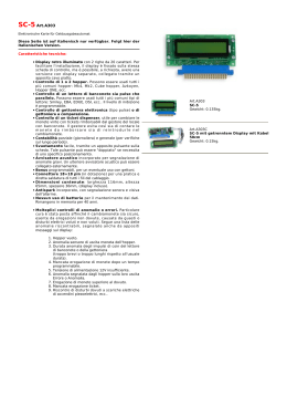
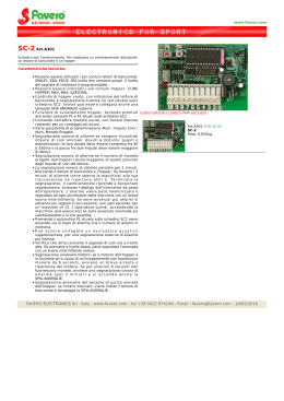
HOPPER
DISCRIMINATOR II
Manuale d’uso
Hopper DISCRIMINATOR II
Mini - Midi
Maxi - Lateral
24Vdc ccTalk
MAXI
MINI
MIDI
Manuale d’uso
®
LATERAL
Progettazione e produzione di sistemi di pagamento, accessori per
videogames e macchine vending
Design and manufacture of payment systems, accessories for videogames and
vending machines
Via Miglioli 23
40024 Castel San Pietro Terme
ITALY
http://www.alberici.net
Tel. + 39 051 944 300
Fax. + 39 051 944 594
[email protected]
1. Introduzione
Congratulazioni per l’acquisto dell’Hopper Discriminator II Alberici.
L’Hopper Discriminator II è stato progettato nei laboratori e fabbricato
nelle officine Alberici S.p.A., per soddisfare le più severe esigenze
della gestione dei pagamenti.
Le tecnologie implementate lo rendono capace di gestire operazioni
multiple, come identificare differenti valori di monete, ed erogare
l’importo complessivo richiesto, in monete miste.
Si installa facilmente sia in macchine AWP / Slot sia in macchine
Cambiamonete. Le sue caratteristiche lo rendono compatibile con
le schede disponibili in commercio.
1.1 Funzionamento
L’ Hopper Discriminator II Alberici S.p.A. può riconoscere e contare vari tipi e valori di moneta
o di gettoni (purché di forma circolare, senza solchi, senza fori o rilievi pronunciati), di diametro
Φ 20 mm - 26,5 mm, e di spessore # 1,7 mm - 3,5 mm.
Identifica e localizza sul disco i tagli disponibili, emette l’importo richiesto sommando i singoli
valori erogati, ricevendo per ciascuno la conferma dal sensore di uscita, e trasmette
l’informazione ccTalk all’host (scheda della macchina). Il riconoscimento di ogni moneta si
ottiene combinando i valori magnetici rilevati da un sistema di sensori induttivi.
La moneta in uscita interrompe momentaneamente il raggio infrarosso modulato fra un l.e.d.
emettitore e un foto-transistor: ogni interruzione indica che è avvenuta l’erogazione di una
moneta, il cui valore era stato subito prima individuato e prescelto. La particolare cifratura del
segnale di controllo impedisce tentativi di frode tramite accecamento del sensore.
Se si verifica un blocco temporaneo, l’elettronica dell’Hopper Discriminator II rileva il sovraassorbimento di corrente, e inverte temporaneamente il senso di rotazione del disco, così da
liberare l’uscita e ristabilire il normale flusso di erogazione.
Elemento esclusivo e peculiare dell’Hopper Discriminator II Alberici è il Sistema brevettato
SPS® o “Smart Pick System”: esso parcheggia le monete di valore più piccolo fino a quando
diventano necessarie per raggiungere precisamente l’importo richiesto. Di conseguenza,
l’Hopper Discriminator II Alberici completa praticamente sempre i pagamenti, rapidamente, e
senza i fastidiosi ritardi dovuti a lunghe ricerche della moneta appropriata - ritardi che
possono anche concludersi con la sospensione del pagamento a causa di ricerca infruttuosa.
Il livello delle monete nella tramoggia può essere controllato mediante sensori ottici che
segnalano il superamento della quota di minimo.
La velocità di erogazione in condizioni standard è di ca. 180 monete al minuto.
1.2 Sicurezza
L’Hopper dovrà essere installato all’interno di sistemi o di apparecchiature che siano
dotati di dispositivi di disconnessione dell’alimentazione di rete.
Prima di togliere o montare l’Hopper Discriminator II, staccare sempre l’alimentazione. Il
dispositivo contiene parti meccaniche in movimento: NON INTRODURRE le dita o oggetti
mentre è in funzione, o quando la macchina è accesa.
ATTENZIONE:
PERICOLO DI LESIONI!
MECHANICAL PARTS IN MOTION
Il disco dell’Hopper Discriminator II espelle le monete ad alta velocità: non posizionare parti
sensibili del corpo o oggetti fragili di fronte alla feritoia di uscita delle monete.
2. Caratteristiche tecniche
Protocollo
Velocità
Capacità monete (Φ24 mm)
Diametri accettati
Spessori accettati
Assorbimento Max
Assorbimento in Stand-by
Tensione di funzionamento
Temperatura di funzionamento
Umidità di riferimento
Dimensioni (mm)
ccTalk 24V
180 monete/min.
775 / 725 / 500 / 325 ( L / MAXI / MIDI / MINI )
20-26,5 mm
1,7-2,6 mm
1A
70 mA
24 Vcc
0°C ÷ 50°C
20% - 75%
131 (l) x 154 (h) x 230 (p)
3. Descrizione meccanica
L’Hopper Discriminator II è disponibile in 4 modelli, differenti per capacità e dimensioni: Mini,
Midi, Maxi, e Laterale. Le sue caratteristiche lo rendono intercambiabile con apparecchi
analoghi sul mercato o già installati.
3.1 Size
HOPPER DISCRIMINATOR II MINI
HOPPER DISCRIMINATOR II
MIDI
HOPPER DISCRIMINATOR II
3.2 Installazione
Eseguire le seguenti semplici operazioni:
. fissare il supporto a slitta in policarbonato al piano della macchina
. posizionare l’hopper e slittarlo orizzontalmente fino al punto di battuta
. prima di collegare l’alimentazione, leggere il capitolo 4
SLITTA DI SUPPORTO
SLITTA DI SUPPORTO
Per smontare l’hopper, tenere premuta verso il basso la linguetta di sblocco del supporto, e
slittare l’hopper verso l’esterno.
Eseguire l’installazione secondo le istruzioni del § 3.2, pena la decadenza della garanzia.
4. Descrizione elettrica
4.1 Alimentazione
L’alimentazione fornita all’Hopper Discriminator II deve essere a 24V in corrente continua. La
sezione dei conduttori deve essere compatibile con gli assorbimenti segnalati di seguito.
4.2 Assorbimenti
Standby
A Vuoto
Sotto carico (*)
Scheda
(+24 Vcc)
40mA
0.48 W
40mA
0.48 W
40mA
0.48 W
Motore
(+24 Vcc)
0mA
0m W
70mA
1.68 W
1A*
24 W
Totale
0.48 W
2.16 W
24.48 W
(*) L’assorbimento del motore sotto carico viene limitato elettronicamente. Il valore indicato
viene raggiunto soltanto per una breve frazione di secondo in caso di rotazione bloccata.
4.3 PIN-OUT del connettore
Il connettore 10-pin ccTalk si trova sul retro dell’hopper, accanto al banco di dip-switch per
l’indirizzamento seriale. Tutti i segnali sono in logica negativa, ovvero il segnale è attivo
quando il suo potenziale è uguale a GND.
4.4 Predisporre l’indirizzo seriale tramite Dip-Switch
Quando necessario, ad esempio quando si usa più di un Hopper Discriminatore sulla stessa
macchina, l’indirizzo seriale dell’hopper Alberici può essere modificato via hardware mediante il
banco di Dip-Switch posti sul retro. I 3 interruttori a slitta presenti possono essere combinati
come da tabella seguente, per ottenere l’inditrizzo conveniente:
Tener presente che lo stato di questi switch viene letto soltanto all’accensione o al reset,
quindi lo spostamento durante il funzionamento non ha alcun effetto fino alla riaccensione.
5. Manutenzione
Prima di qualsiasi operazione di manutenzione, spegnere l’alimentazione e staccare il cavo.
Pulire il disco dell’Hopper Discriminator II almeno ogni 100.000 erogazioni, mediante un getto
di aria compressa.
La conformazione della sede del sensore d’uscita impedisce l’accumularsi dello sporco, il che
riduce la necessità di pulizie frequenti. E’ comunque consigliabile pulire anche il sensore
quando si pulisce il disco.
Controllare spesso, ad esempio in occasione di riempimenti manuali, che il disco o la
tramoggia non contengano detriti o monete deformate, e rimuovere i corpi estranei senza
indugio. La loro presenza può ostruire l’uscita, ostacolare la rotazione del disco, falsare la
lettura dei valori, guastare i componenti dell’Hopper e rovinare le sue prestazioni.
Per pulire l’Hopper Discriminator II, sollevarne lo scivolo, e soffiare aria compressa non umida
sui dischi, sulle finestrelle dei sensori (visibili attraverso i fori portamoneta), e attraverso la
feritoia di erogazione.
Per qualunque operazione di pulizia che richieda lo smontaggio di particolari, si raccomanda di
spedire l’Hopper Discriminator II alla Alberici S.p.A., che provvederà a pulirlo e ad eseguire
anche gli eventuali aggiornamenti necessari.
6. ccTalk protocol
6.1
ccTalk commands
NOTA: nella tabella sottostante sono elencati i comandi necessari per implementare l’Hopper
Discriminator II sulle schede gioco.
Per visionare la lista dettagliata delle risposte dell’Hopper Discriminator II Alberici ai comandi
dell’host (scheda gioco), cfr. § 6.2 ccTalk Protocol nella pag. seguente.
Code / Hex.
Command header
Note
254
FE
Simple poll
Return ACK
253
FD
Address poll
MDCES support
246
F6
Request manufacturer id
“Alberici”
245
F5
Request equipment category id
“Payout”
244
F4
Request product code
“AH DSC 1”
242
F2
Request serial number
[Ser nr-L][Ser nr][Ser nr-H]
241
F1
Request software revision
un.n pm.m.m
217
D9
Request payout high/low status
Return empty/full status
197
C5
Calculate ROM checksum
[Mon][Prog][Data]
164
A4
Enable hopper
Enable = 0xA5
163
A3
Test hopper
Supported
134
86
Dispense hopper value
Supported
133
85
Request hopper polling value
Supported
132
84
Emergency stop value
Supported
131
83
Request hopper coin value
Supported
130
82
Request indexed hopper dispense count
Supported
1
1
Reset device
Software reset
6.2
cctalk Protocol of Hopper Discriminator II
HOPPER DISCRIMINATOR II - ccTalk PROTOCOL
ccTalk® communication protocol is the Money Controls (formally Coin Controls) serial
communication protocol for low speed control networks. It was designed to allow the
interconnection of various cash handling devices (Hopper, Card reader, Bill validators, Coin
selectors etc.), mostly in AWP and gaming Industry, but also in other devices that use those
components.
ccTalk® is an open standard. All documentation is available at web site:
www.cctalk.org.
Communication protocol of Alberici Hoppers AH04.. is implemented according to generic
specification 4.4
1 Communication specifications
ccTalk serial communication is derivation of RS232 standard.
Low data rate NRZ (Non Return to Zero) asynchronous communication:
Baud rate 9600, 1 start bit, 8 data bits, no parity, 1 stop bit.
RS232 handshaking signals (RTS, CTS, DTR, DCD, DSR) are not supported.
Message integrity is controlled by means of checksum calculation.
1.1 Baud rate
The baud rate of 9600 was chosen as compromise between cost and speed.
Timing tolerances is same as in RS232 protocol and it should be less than 4%.
1.2 Voltage level
To reduce the costs of connections the “Level shifted “ version of RS232 is used. The idle state
on serial connector is 5V, and active state is 0V.
Mark state (idle) +5V nominal from 3.5V to 5V
Space state (active) 0V nominal from 0.0V to 1.0V
Data I/O line is “open collector” type, so it is possible to use device in systems with
different voltage (12V pull up in older devices).
1.3 Connection
The connection of Hopper at network is achieved by means of 10 pole IDC connector
compatible with Azkoyen standard ccTalk 2+2 (Two wires for power supply + and two for GND
connector). Connector is used for power supply and communication as well.
For schematics and and connector appearance see images and tables below.
Fig. 1 AH04 - ccTalk connector
PIN Nr.
1
2
3
4
5
6
7
8
9
10
Function
cc Talk Data
Not used
Not used
GND
Not used
Not used
+24 V
GND
Not used
+24 V
Table 1 AH04 ccTalk connector
1.4 Message structure
Each communication sequence consists of two message packets.
Message packets for simple checksum case is structured as follows:
[ Destination address ]
[ Nr. of data bytes ]
[ Source address ]
[ Header ]
[ Data 1 ]
...
[ Data n ]
[ Checksum ]
There is an exception of message structure when device answer to instruction 253 “Address
poll” and 252 “Address clash”1. The answer consists of only one byte representing address
delayed for time proportional to address value or random delay.
For CRC checksum case format is:
[ Destination address ]
[ Nr. of data bytes ]
[ CRC 16 LSB ]
[ Header ]
[ Data 1 ]
...
[ Data n ]
[ CRC 16 MSB ]
1.4.1 Address
Address range is from address 0 to address 255. Address 0 is special case or so called
“broadcast” address and address 1 is default host address.
The recommendation for address value of different devices are presented in table 2.
Device category
Address
Additional addr.
Note
Coin Acceptor
2
11 - 17
Coin validator, selector, mech...
Payout
3
4 - 10
Hopper
Bill validator
40
41 - 47
Banknote reader
Card Reader
50
-
Display
60
Alphanumeric LC display
Keypad
70
-
Dongle
80
Meter
90
Replacement for el.mec. counters
Power
100
Power supply
85
Safety equipment
Table 2 Standard address for different types of devices
Address for ALBERICI Hoppers is factory set to value 3, but the user can change the default
address by setting the Hopper PCB switch.
1.4.2 Number of data byte
Number of data byte in each transfer could be from 0 to 252.
Value 0 means that there are no data bytes in the message, and total length of message
packet will be 5 bytes. Although theoretically it will be possible to send 255 bytes of data
because of some limitations in small micro controllers the number is limited to 252 .
2
1.4.3 Command headers (Instructions)
Total amount of possible ccTalk command header is 255, with possibility to add sub-headers
using headers 100, 101, 102 and 103.
Header 0 stands for ACK (acknowledge) replay of device to host.
Header 5 stands for NAK (No acknowledge) replay of device to host.
Header 6 is BUSY replay of device to host.
In all three cases no data bytes are transferred. Use of ACK and NAK headers is explained
separately for each specific message transfer.
Commands are divided in to several groups according to application specifics:
-
Basic general commands
Additional general commands
Commands for Coin acceptors
Commands for Bill validators
Commands for Payout
MDCES commands
1.4.4 Data
There is no restrictions for data format use. Data could be BCD (Binary Coded
Decimal)numbers, Hex numbers or ASCII strings. Interpretation as well as format is specific to
each header use, and will be explained in separate chapter.
1.4.5 Checksum
Message integrity during transfer is checked by use of simple zero checksum calculation.
Simple checksum is made by 8 bit addition (modulus 256) of all the bytes in the message.
If message is received and the addition of all bytes are non-zero then an error has occurred .
3
1.5 Timing specification
The timing requirements of ccTalk are not very critical but there are some recommendation.
1.5.1 Time between two bytes
When receiving bytes within a message packet, the communication software must wait up to
50 ms for next byte if it is expected. If time out occurs, the software should reset all
communication variables and get ready to receive next message. The inter byte delay during
transmission should be ideally less than 2 ms and not greater than 10 ms.
1.5.2 Time between command and replay
The time between command and reply is dependent on application specific for each command.
Some commands return data immediately, and maximum time delay should be within 10 ms.
Other commands that must activate actions in device may return reply after action is finished.
1.5.3 Start-up time
After the power-up sequence Hopper should be ready to accept and answer to a ccTalk
message within time period of less than 250 ms.
During that period all internal check-up and system settings must be done, and hopper should
1.6 Error handling
If slave device receive the message with bad checksum or missing data no further action is
taken and receive buffer will be cleared.
Host software should decide to re-transmit message immediately or after a fixed amount of
time. In case when host receive message with error it has same options.
2. Hopper Command header set
Command header set, that host could use in communication with Hopper is given in table 3.
Code / Hex.
Command header
Note
254
FE
Simple poll
Return ACK
253
FD
Address poll
MDCES support
246
F6
Request manufacturer id
“Alberici”
245
F5
Request equipment category id
“Payout”
244
F4
Request product code
“AH DSC 1”
242
F2
Request serial number
[Ser nr-L][Ser nr][Ser nr-H]
241
F1
Request software revision
un.n pm.m.m
217
D9
Request payout high/low status
Return empty/full status
197
C5
Calculate ROM checksum
[Mon][Prog][Data]
164
A4
Enable hopper
Enable = 0xA5
163
A3
Test hopper
Supported
134
86
Dispense hopper value
Supported
133
85
Request hopper polling value
Supported
132
84
Emergency stop value
Supported
131
83
Request hopper coin value
Supported
130
82
Request indexed hopper dispense count
Supported
1
1
Reset device
Software reset
Table 3 List of Hopper Discriminator II ccTalk command headers
Command headers are divided in to 4 different groups:
- Common command headers
- Hopper command headers
- MDCES command headers
2.1
ALBERICI specific command headers
2.1.1 Command header 254 [hexFE], Simple poll
The fastest way for host to detect all attached devices in ccTalk network.
Addressed device - Hopper answer with ACK (Acknowledge).
If within predicted amount of time Hopper does not answer, probably is not connected,
powered or simple not working properly.
Message format is:
Host sends: [Dir][00][01][FE][Chk]
Hopper answer: [01][00][Dir][00][Chk]
Hopper default address is 3, example of message packet is:
Host sends: [03][00][01][FE][FE]
Hopper answer: [01][00][03][00][FC] ACK message
2.1.2 Command header 246 [hexF6], Request manufacturer ID
Hopper answer with ASCII string representing manufacturer name. In this case the hopper
answer will be ‘Alberici ‘.
Message format is:
Host sends: [Dir][00][01][F6][Chk]
Hopper answer: [01][Nr.b][Dir][00][a1][a2]...[an][Chk]
[Nr.b] is number of data bytes-characters sent by Hopper, and a1 to an are ASCII characters.
The example of message packet is:
Host sends: [03][00][01][F6][06]
Hopper answer: [01][0E][03][00][41][6C][62][65][72][69][63][69][86]
2.1.3 Command header 245 [hexF5], Request equipment category ID
The answer to command header is standardized name for Hopper. Hopper will answer with
ASCII string of characters representing standard name for that type of device 'Payout'.
Message format is:
Host sends: [Dir][00][01][F5][Chk]
Hopper answer: [01][06][Dir][00][50][61][79][6F][75][74][Chk]
Number of data byte is always 6, hex [06].
Example of message packets for hopper (address 3) is:
Host sends: [03][00][01][F5][07]
Hopper answer: [01][06][03][00][50][61][79][6F][75][74][74]
2.1.4 Command header 244 [hexF4], Request product code
Hopper answer with ASCII string of character, representing its factory type.
For Alberici Hoppers it is 'AH DSC 1'. Message format is:
Host sends: [Dir][00][01][F4][Chk]
Hopper answer: [01][nr.byte][Dir][00][a1][a2]...[an][Chk]
Number of data bytes sent by Hopper is 8, hex [08].
Example of message packets for Hopper (address 3) is :
Host sends: [03][00][01][F4][08]
Hopper answer: [01][08][03][00][41][48][20][44][43][69][20][01][20]
2.1.5 Command header 242 [hexF2], Request serial number
Hopper answer with three byte serial number.
Message format is:
Host sends: [Dir][00][01][F2][Chk]
Hopper answer: [01][03][Dir][00][Ser.1-LSB][Ser.2][Ser.3-MSB][Chk]
The first data byte sent is LSB of serial number.
Example of message packets for Hopper (address 3) and serial number 1234567, hex
[BC][61][4E] is:
Host sends: [03][00][01][F2][0A]
Hopper answer: [01][03][03][00][4E][61][BC][8E]
2.1.6 Command header 241 [hexF1], Request software revision
Hopper return ASCII string of character representing software version and revision. Message
format is:
Host sends: [Dir][00][01][F1][Chk]
Hopper answer: [01][Nr.b][Dir][00][a1][a2]...[an][Chk]
Number of data bytes in ASCII string is not limited and each producer has it’s own system of
labelling. Example of message packets for Hopper(address 3) is:
Host sends: [03][00][01][F1][0B]
Hopper answer: [01][0B][03][00][75][31][2E][30][20][70][31][2E][30][2E][30][70]
In this case the Hopper answer is ‘u1.0 p1.0.0’. New generation of Hopper controllers has
main firmware(program)FLASH up-grade capability built in small monitor program.
Monitor program version is marked with ASCII letter 'u' and two digit's for minor and major
changes. Main program is marked with letter 'p' and three digit's for changes.
First digit is major program changes, second digit is for minor program changes and third is for
error or bug corrections.
2.1.7 Command 197 [hexC5], Calculate ROM checksum
Hopper respond with three bytes of micro controller internal memory checksum.
First byte is monitor program FLASH checksum, second is main program FLASH checksum
and third is data(in RAM) checksum. Any changes in program memory or data will change the
respond of hopper. Message format is:
Host sends: [Dir][00][01][C5][Chk]
Hopper answer: [01][3][Dir][00][Cksum 1][Cksum 2][Cksum 3][Chk]
Example of message string for Hopper(address 3) is:
Host sends: [03][00][01][C5][37]
Hopper answer: [01][03][03][00][53][6E][CC][6C]
2.1.8 Command header 1 [hex01], Reset device
After acceptance of command Reset hopper execute software reset and clear all variables in
RAM or set them at the default value, including different counters, and any buffers. After reset
hopper replay with ACK message.
Host software must re enable hopper to perform a new payout. Message format is:
Host sends: [Dir][00][01][01][Chk]
Hopper answer: [01][00][Dir][00][Chk] ACK message
Example of message packets for hopper (address 3) is:
Host sends: [03][00][01][01][FB]
Hopper answer: [01][00][03][00][FC] ACK message
2.2
Hopper specific command headers
Hoppers are using some specific commands, for pay-out control, test of status and description.
Some of commands are shared with other devices like banknote reader or hopper devices, but
has different response or message format.
2.2.0 Command header 217 [hexD9],Request Payout Hi-Lo status
This command allow the reading of High/Low level sensor in payout systems.
Hopper answer with one byte that describe the sensors status.
The meaning of bits in status byte is the following:
Bit 0 - Low level sensor status.
0 – Higher than or equal to low level trigger
1 – Lower than low level trigger
Bit 1 – High level sensor status
0 - Lower than high level trigger
1 - Higher than or equal to high level trigger
Bit 4 - Low level sensor support
0 – Features not supported or fitted
1 - Features supported and fitted
Bit 5 - High level sensor support
0 - Features not supported or fitted
1 - Features supported and fitted
Bit's 2,3,6,7 are reserved bits
Message format is:
Host sends: [Dir][00][01][D9][Chk]
Hopper answer: [01][01][Dir][00][d1][Chk]
Example of message packets for Hopper(address 3) AH24 with no coins(empty) is:
Host sends: [03][00][01][D9][23]
Hopper answer: [01][01][03][00][11][EA]
Only low sensor is supported, and hopper is empty.
2.2.1 Command header 164 [hexA4], Enable Hopper
This command enable hopper dispense. It must be sent once after power-on, Reset or
Emergency stop command but before Dispense hopper coins command.
Message string format is:
Host sends: [Dir][01][01][A4][d1][Chk]
Hopper answer: [01][00][Dir][00][Chk] ACK
Data [d1] must be hex [A5] in order to enable hopper. Any other code will disable it.
Example of message packets for Hopper(address 3) is:
Host sends: [03][01][01][A4][A5][B2]
Hopper answer: [01][00][03][00][FC] ACK
2.2.2 Command header 163 [hexA3], Test Hopper
This command is used to test hopper hardware and report some problems in during dispense
of coins. As response to that command hopper send to host a 2 bytes of data.
Each byte represent bit mask that show various hopper error. Bit meaning is shown below :
[Error mask 1]
Bit 0 – Absolute maximum current exceeded
Bit 1 – Payout time-out occurred
Bit 2 – Motor reverse during last payout to clear a jam
Bit 3 – Opto fraud attempt, path blocked during idle
Bit 4 – Opto fraud attempt, short circuit during idle
Bit 5 – Opto blocked permanently during payout
Bit 6 – Power up detected
Bit 7 – Payout disabled
[Error mask 2]
Bit 0 – Opto shorted during payout
Bit 1 – Flash data crc error
Bit 2 – Use other hopper to pay
Bit 3 – NU read 0
Bit 4 – Motor reverse limit end
Bit 5 – Unrecognized coin reverse limit
Bit 6 – Sorter blocked
Bit 7 – PIN mechanism active
Message string format is:
Host sends: [Dir][00][01][A3][Chk]
Hopper answer: [01][02][Dir][00][err 1][err 2][Chk]
Example of message packets for Hopper(address 3) is:
Host sends: [03][00][01][A3][59]
Hopper answer: [01][02][03][00][C0][00][BA]
Such response is example of hopper state after power-up.
2.2.3 Command header 134 [hex86], Dispense hopper value
This command is used to dispense coin value from a discriminator hopper. The coin value is
based as the lowest unit of coin(1 cent, 1 pence etc.). Maximum possible value to pay with one
instruction is 65535(ie. cents or 655 Eur).
Hopper must be enabled before use of this command.
Message format is:
Host sends: [Dir][05][01][86][sn1][sn2][sn3][Val-lo][Val-hi][Chk]
Hopper answer: [01][00][Dir][00][Chk] ACK or NAK
Data string [sn1][sn2][sn3] is serial number, [Val-hi/lo] value to pay and [cnt] is number of
pay out events!
First format message string example for hopper with ser. number (dec 1), to pay out 5 Euro is:
Host sends: [03][05][01][86][01][00][00][F4][01][7B]
Hopper answer: [01][01][03][00][FC] ACK
2.2.4 Command header 133 [hex85], Request hopper polling value
This command will return the value of four counters that are representing the state of current
payment or last payment. These four counters are:
[Event Counter]
Each time a valid Dispense hopper coins command is received, event counter is incremented
till it reach the value of 255. After that next pay out command will set this value to 1.
After power down or reset, value of event counter is 0.
[Payout value remaining]
This 2 byte counters will decrement for coin value after each coin is dispensed till it reach the
value 0(both bytes) or stop of pay out. It shows us how much value is left to pay. Counter is
set to new value after a valid dispense hopper value command.
It is cleared after Reset, after Emergency stop or after automatic pay stop.
[Last Payout: value paid]
This 2 byte counters will increment during the pay out with each dispensed coin.
The value of counter is saved in non-volatile FLASH memory in case if power failure occourr
during the pay out cycle or after that. It is cleared at the begining of nex pay out comand. It
shows us how much value has been paid out since last dispence command was lounched.
[Last Payout: value unpaid]
This 2 byte counters will also decrement during the pay out cycle in same way as counter
[Payout value remaining]. The difference is that this counter will be saved in non-volatile
FLASH memory if power failure occourr during or after(value 0) pay out. It show us how much
value was unpaid during last payout.
Message format is:
Host sends: [Dir][00][01][85][Chk]
Hopper answer: [01][07][Dir][00][d1][d2-l][d2-h][d3-l][d3-h][d4-l][d4-h][Chk]
Example of message packets for Hopper(address 3) is:
Host sends: [03][00][01][85][77]
Hopper answer: [01][07][03][00][01][00][00][00][00][96][00][5E]
In this example hopper didn't not perform a complete payout. The last payout was 3 Euro and
50 censts of 5 Euro to be paid.
2.2.5 Command header 132 [hex84], Emergency stop value.
This command immediately halt the payout sequence(break the motor) and reports back
the value of coins which failed to be paid out. Hopper answer has 100 ms delay for last coin
to exit. After Emergency stop value command, the hopper will be disabled.
To perform new payout sequence, hopper must be re-enabled.
Message format is:
Host sends: [Dir][00][01][84][Chk]
Hopper answer: [01][02][Dir][00][d1-l][d1-h][Chk]
Example of message packets for Hopper (address 3) is
Host sends: [03][00][01][84][78]
Hopper answer: [01][02][03][00][7E][04][78]
Data bytes hex[7E][04] represent hex 047E or dec 1150. That mean that there is 11 Euro and
50 cents left unpaid due to Emergency stop.
2.2.13 Command header 131 [hex83], Request hopper coin value.
This command return the “name” of specified coin as well as its value.
Coin name is standardized 6 byte ASCII characters . It is possible to program different coin
names that describe the one used in hopper. Unprogrammed coins has code:'------' .
This code is reserved for unknown(any type) of coin.
4
Message format is:
Host sends: [Dir][01][01][83][01][Chk]
Hopper answer: [01][08][Dir][00][a1][a2][a3][a4][a5][a6][Val-lo]
[Val-hi][Chk]
Data a1 to a6 represent the coin “name”(description). Data Val-lo and hi are coin value.
Example of message packets for Hopper(address 3) coin nr. 1(2 Euro) is:
Host sends: [03][01][01][83][77]
Hopper answer: [01][08][03][00][45][55][32][30][30][41][C8][00][BF]
Data bytes hex[45][55][32][30][30][41] are ASCII 'EU200A'.
Data bytes hex[C8][00] represent hex 00C8 or dec 200, the value of 2 Euro in cents.
2.2.14 Command header 130 [hex82], Request indexed hopper dispense count.
This command show the total number of each type of coins dispensed by hopper.
Each coin counter is non-volatile and has three bytes. LS byte is sent first.
Message format is:
Host sends: [Dir][01][01][82][coin nr.][Chk]
Hopper answer: [01][03][Dir][00][d1][d2][d3][Chk]
Example of message packets for Hopper(address 3) and second coin is:
Host sends: [03][00][01][82][02][54]
Hopper answer: [01][03][03][00][54][00][00][A5]
In this example hopper dispensed 84 coins(hex 54) programmed on second channel.
Maximum value of dispensed coins stored in hopper FLASH is 16 777 215.
2.3
MDCES command headers
MDCES stands for Multi-Drop Command Extension Set, or so called Multi-drop bus commands.
2.3.1 Command header 253 [hexFD], Address poll
This command is usually sent as a broadcast message by the host to determinate all address
of device attached on ccTalk network. Hopper will answer with only one byte (non-standard
message format), after a delay that is proportional to address value multiplied with 4
milliseconds.
Message format is:
Host sends: [00][00][01][FD][Chk] Brodcast message
Hopper answer: Dly=4x[Address] -> [Address]
Example of message packets for Hopper (address 3) is:
Host sends: [00][00][01][FD][02]
Hopper answer: Dly=12 ms -> [03] Address is 3
Example of message packets for Hopper (address 250) is:
Host sends: [00][00][01][FD][02]
Hopper answer: Dly=1 s -> [FA] Address is 250
3.0 Setting Hopper Address via PCB DIP-sw
The default address of Alberici hoppers can be changed by setting the onboard switches.
The following table shows the possible Switch combinations to set the Hopper address.
Sw 3
Off
Off
Off
Off
On
On
On
On
Sw 2
Off
Off
On
On
Off
Off
On
On
Sw 1
Off
On
Off
On
Off
On
Off
On
Address
3
4
5
6
7
8
9
10
Table 5 Address selection for hoppers AH03-CD.
The board reads the address dip-switches only after power-up or reset.
Therefore anychange of address made by means of the switch-row during
normal operation will have no effect.
1For details see ccTalk44-2.pdf, Address poll
2252 bytes of data, source address, header and checksum (total of 255 bytes)
3See Error handling
4Refer to Appendix 3.1 of protocol document cctalk43-3.pdf
NOTA:
La Alberici S.p.A. ri riserva il diritto di apportare modifiche alle specifiche
tecniche dell’apparecchiatura descritta in qualunque momento e senza preavviso, nell’ambito
del perseguimento del miglioramento continuo del proprio prodotto.
®
Progettazione e produzione di sistemi di pagamento, accessori per videogames e macchine
vending
Design and manufacture of payment systems, accessories for videogames and vending
machines
Via Miglioli 23
40024 Castel San Pietro Terme
ITALY
http://www.alberici.net
Tel. + 39 051 944 300
Fax. + 39 051 944 594
[email protected]
Scaricare