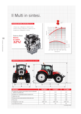
ISTR 48+ MULTI rev2
12-12-2002
11:16
Pagina 1
INDICE
Pag.1
Descrizione comandi
Pag.2
Installazione
Pag.5
Collegamento elettrico
Pag.5
Installazione dell'antenna
Pag.5
Uso dell'ALAN 48 PLUS MULTI
Pag.6
Selezione bande di frequenza
Pag.6
Tabella bande di frequenza
Pag.6
Caratteristiche tecniche
Pag.7
I T A L I A N O
Introduzione
ALAN 48 PLUS MULTI operante sui canali della banda cittadina, ha come importante ed
innovativa peculiarità di essere controllato a microprocessore. Frutto delle più avanzate
tecnologie, garantisce il massimo delle prestazioni e del rendimento. Apparato di ottima
qualità, è stato costruito utilizzando i migliori componenti. La circuiteria, tutta allo stato
solido, è montata su robusti circuiti stampati, garantendo un uso per molti anni anche nelle
situazioni più gravose. I tasti retro illuminati facilitano l’utilizzo notturno. ALAN 48 PLUS
MULTI è sintetizzato in frequenza tramite circuito PLL, soluzione che permette di generare, tramite un quarzo le frequenze richieste, consentendo una maggior affidabilità e flessibilità nel controllo delle stesse.
1
ISTR 48+ MULTI rev2
12-12-2002
11:16
Pagina 2
DESCRIZIONE COMANDI
1
3
8
17
9
12
13
14
CB
ANL
LOCAL
PA
OFF
DX
CHANNEL
88
LOCK
CH FM
AM
SCAN
LOW
3
5
9
+30
1
0.5
1
2
3
4
SIG
PWR
RX
M1
M2
M3
M4
DW
EMG
TX
EMG M1 M2 M3 M4 DW
Q. UP
MIC
ON/OFF VOL
SQUELCH
RF GAIN
Q. DOWN
MIC GAIN
AM/FM
SCAN
LCR
48 PLUS MULTI
2
4
5
6
10
7
11
15
16
1. Ricerca manuale canali
2. Presa microfono: Inserire lo spinotto nell’apposita presa.
3. Display retroilluminato multifunzione
C J
A
88
B
LOCK
K
CH FM
AM
E
I
SCAN
LOW
3
5
9
+30
1
0.5
1
2
3
4
SIG
PWR
RX
TX
EMG M1 M2 M3 M4 DW
F
D
H
G
A. Numero canali selezionati
B. Indicatore di intensità del segnale ricevuto e di potenza di segnale trasmesso
C. AM/FM: indicatore del modo di emissione
D.RX/TX: indicatore ricezione (RX) e trasmissione (TX)
E. SCAN: indicatore funzione SCAN attivata
F. EMG: indicatore lampeggiante canale d’emergenza attivato
G.M1-M2-M3-M4: indicatori memorie canali
H.DW: funzione Dual Watch attivata
I. Indica la banda di frequenza selezionata.
J. LOW: viene visualizzato quando la radio trasmette in bassa potenza (condizione che
si verifica solo per determinate bande di frequenza – vedi tabella bande).
K. LOCK: Attivazione del blocco tastiera (UP/DOWN) del microfono.
2
ISTR 48+ MULTI rev2
12-12-2002
11:16
Pagina 3
4. Manopola ON/OFF-VOLUME: Posizione ‘’OFF’’: Apparato spento; Posizione ‘’Volume’’:
Ruotando la manopola, regolare il volume al livello desiderato. Con il selettore ‘’PACB’’. Accensione apparato: in posizione ‘’PA’’, la manopola regola il livello di uscita di
bassa frequenza.
5. Manopola ‘’Squelch’’ regolazione livello di soglia della ricezione: per la massima sensibilità del ricevitore è preferibile che il comando sia regolato solo al preciso livello
dove il rumore di fondo del ricevitore viene eliminato.
6. Manopola ‘’RF-GAIN’’: Controllo della sensibilità in ricezione: ruotando la manopola
in senso orario, si ottiene un’aumento della sensibilità; ruotandola in senso antiorario,
si ottiene una diminuzione della sensibilità. Ciò è utile in presenza di forti segnali.
7. Manopola ‘’MIC-GAIN’’: Controllo dell’amplificazione microfonica in trasmissione:
utilizzare il microfono ricercando sperimentalmente la posizione ottimale sia come
distanza dalla bocca, che di livello di amplificazione, in modo da ottenere la migliore
modulazione possibile.
9. Pulsante "EMG": Canale d’emergenza: premendo questo tasto si ci posizionerà automaticamente sul canale 9 (canale d’emergenza). Sul display lampeggerà “EMG” e non
sarà possibile cambiare accidentalmente il canale.
10/11. PULSANTI “Q.UP/Q.DOWN’’: Per selezionare rapidamente i canali verso l’alto (UP)
o verso il basso (DOWN).
12. Selettore ‘’CB-PA’’: Posizione ‘’CB’’: in questa posizione, l’apparato è attivo come ricetrasmettitore; posizione ‘’PA’’: questo modo di funzionamento è possibile solo se
viene collegato un altoparlante alla presa PA sul retro. In questo caso la manopola
‘’Volume’’ viene usata come controllo dell’amplificazione.
13. Selettore ‘’ANL/OFF’’: Posizione ‘’ANL’’: si attiva il limitatore automatico di rumore. È
utile per eliminare i disturbi di tipo impulsivo (generati ad esempio dal motore dell’auto). Posizione OFF: disattivato.
14. Selettore "Local/DX": attenuatore di segnale. LOCAL: per ricevere solo segnali forti;
DX: per segnali deboli.
15. Pulsante “AM/FM”(LCR): Per selezionare il modo di emissione (AM/FM). Se lo si
preme all’accensione con il tasto “SCAN”, seleziona la banda operativa. Le relative
scelte saranno visualizzate sul display. Se si seleziona un banda di frequenza che opera
solamente la modalità FM, il tasto “AM/FM” attiva la funzione LCR (richiamo ultimo
canale selezionato).
16. Pulsante "SCAN": tramite questo comando si potrà ricercare automaticamente un
canale occupato.
• Ruotare lo Squelch in senso orario fino a quando non sparisce il rumore di fondo.
3
I T A L I A N O
8. Pulsanti ‘’M1-M2-M3-M4'’: Questi pulsanti permettono di memorizzare e di richiamare all’occorrenza 4 canali a piacimento precedentemente memorizzati. Per memorizzare i canali: selezionare il canale desiderato tramite la manopola CHANNEL o i tasti
UP/DOWN. Premere M1 per circa 3 secondi per memorizzare il canale prescelto nella
memoria M1. Ripetere le stesse operazioni per le altre memorie a disposizione.
ISTR 48+ MULTI rev2
12-12-2002
11:16
Pagina 4
• Premere il pulsante "SCAN". Il ricetrasmettitore scansionerà automaticamente e
ripetutamente tutti i canali fino a quando non troverà un canale occupato.
Se lo si preme all’accensione con il tasto “AM/FM”, seleziona la banda operativa. Le
relative scelte saranno visualizzate sul display.
17. Tasto DW: con questo tasto é possibile rimanere sintonizzati contemporaneamente su
due canali a scelta dell’utente.
Questa funzione permette il monitoraggio di un secondo canale. In presenza di un
segnale sul secondo canale, il ricevitore commuterà automaticamente su quest’ultimo.
Il monitoraggio riprenderà dopo 4 secondi dal cessare del segnale.
Per attivare la funzione Dual Watch, operare come segue:
a. Selezionare il canale desiderato mediante il selettore canali.
b. Premere il tasto “DW” (sul display lampeggia la sigla DW).
c. Selezionare il secondo canale.
d. Premere nuovamente il tasto “DW”: la scritta DW smetterà di lampeggiare e sarà
evidenziata sul display in modo fisso.
e. Per annullare la funzione premere “DW”.
PANNELLO POSTERIORE
18
19
20
21
S. METER
PA
EXT
22
ANTENNA
POWER
13.8V DC
18. CONNETTORE ANTENNA: È previsto il connettore SO 239.
19. PRESA S. METER: Permette il collegamento di uno strumento esterno.
20. PRESA PA: Tramite il collegamento ad un altoparlante esterno, permette di utilizzare
l’apparato come amplificatore audio.
21. PRESA EXT: Presa altoparlante esterno (questo collegamento esclude l’uso dell’altoparlante interno).
22. POWER 13.8 Vdc: presa di alimentazione.
4
ISTR 48+ MULTI rev2
12-12-2002
11:16
Pagina 5
2
3
MICROFONO
1. PTT: Pulsante di trasmissione
2. Pulsanti UP/DOWN: selezione canali verso
l’alto (UP) e verso il basso (DN)
1
3. Tasto LOCK: permette di bloccare i tasti
UP/DOWN del microfono.
4. Connettore microfonico 6 PIN
4
Ricercare e localizzare, sul mezzo mobile, la posizione per installare l’apparato, utilizzando
la staffa di supporto in dotazione o, eventualmente, un estraibile. Tale posizionamento deve
essere fatto in modo da non creare intralcio a chi guida, ma deve anche essere facilmente accessibile. Praticare i fori (diametro di circa 3 mm) nella carrozzeria per il fissaggio
con le viti. Posizionare l’apparato nella staffa di fissaggio. Controllare che le viti siano ben
serrate, in considerazione delle notevoli e vibrazioni create dal mezzo mobile.
COLLEGAMENTO ELETTRICO
Prima di procedere in questa operazione, controllare che il ricetrasmettitore sia spento
(posizione OFF= la manopola del volume completamente girata a sinistra, dopo lo scatto).
L’apparato è dotato di un cavetto di alimentazione bicolore con un portafusibile inserito sul
cavo rosso (positivo). Nel collegamento, è molto importante rispettare la polarità anche se
l’apparato è protetto contro l’inversione accidentale. Di norma si identifica il polo positivo
con il colore rosso o con il segno ‘’+’’, e il polo negativo con il colore nero o con il segno
“-”.
Gli stessi segni (o colori) identificativi li troveremo sulla batteria (accumulatore od altro) e
nella scatola dei fusibili dell’automobile. Si raccomanda di collegare in modo corretto e
stabile i terminali del cavetto alla batteria.
INSTALLAZIONE DELL’ ANTENNA
Informazioni utili:
1. Installare l’ antenna nella parte più alta del veicolo.
2. Maggiore è la lunghezza dell’ antenna e migliore sarà il suo rendimento.
3. Se possibile, installare l’antenna al centro della superficie metallica scelta.
4. Tenere il cavo dell’antenna lontano da fonti di disturbi elettrici.
5. Assicurarsi di avere una buona massa.
6. Evitare danni ai cavi.
Attenzione: Non usare mai la radio CB senza aver installato un’antenna appropriata per
non correre il rischio di danneggiare il trasmettitore; per la stessa ragione controllare
periodicamente il ROS tramite l’apposito strumento.
5
I T A L I A N O
INSTALLAZIONE
ISTR 48+ MULTI rev2
12-12-2002
11:16
Pagina 6
USO DELL’ ALAN 48 PLUS MULTI
Dopo aver installato il vostro CB e la vostra antenna, seguire attentamente le seguenti
istruzioni per raggiungere un funzionamento soddiafacente del vostro apparato.
1. Avvitare la spina nella presa del microfono sul pannello e controllare il montaggio.
2. Assicurarsi che l’antenna sia collegata al proprio connettore.
3. Assicurarsi che lo squelch sia completamente ruotato verso sinistra.
4. Accendere l’apparato e regolare il comando del volume per un buon livello sonoro.
5. Selezionare il canale desiderato.
6. Per trasmettere, premere il pulsante di trasmissione PTT sul microfono.
7. Per ricevere, rilasciarlo.
SELEZIONE BANDE DI FREQUENZA
La scelta delle bande di frequenza deve essere eseguita a seconda del paese nel quale si
intende operare.
Procedimento:
1. Spegnere la radio.
2. Accendere l’apparecchio premendo contemporaneamente i tasti “AM/FM” e “SCAN”.
3. Ruotare la manopola “CHANNEL” e selezionare la banda di frequenza desiderata (vedi
tabella bande).
4. Premere il tasto “AM/FM” per terminare la selezione.
NOTA1: nella banda di frequenza UK è possibile selezionare direttamente la banda EC premendo il tasto “AM/FM” per 2 secondi circa.
NOTA2: Se si seleziona una banda di frequenza che opera solamente la modalità FM, il
tasto “AM/FM” attiva la funzione LCR (richiamo ultimo canale selezionato).
TABELLA BANDE DI FREQUENZA
Sigla
sul display
I
I2
D
D2
EU
EC
E
F
UK
Paese
Italia 40 CH AM/FM 4Watt
Italia 34 CH AM/FM 4Watt
Germania 80 CH FM 4Watt / 12 CH AM 1Watt
Germania 40 CH FM 4Watt / 12 CH AM 1Watt
Europa 40 CH FM 4Watt / 40 CH AM 1Watt
CEPT 40 CH FM 4Watt
Spagna 40 CH AM/FM 4Watt
Francia 40 CH FM 4Watt / 40 CH AM 1Watt
Inghilterra 40 CH FM 4 Watt frequenze inglesi + EC 40 CH FM 4Watt
frequenze CEPT
ATTENZIONE:
Lo standard sicuramente riconosciuto in tutti i paesi europei è 40CH FM 4W (EC) - Vedi
tabella “Restrizioni all’uso”
6
ISTR 48+ MULTI rev2
12-12-2002
11:16
Pagina 7
CARATTERISTICHE TECNICHE
GENERALI
Canali ..........................................................................................40 FM (vedi tabella bande)
Gamma di frequenza ..........................................................................25.615 – 30.105 MHz
Controllo di frequenza ..................................................................................................a PLL
Temperatura........................................................................................................-10°/+55° C
Tensione di alimentazione ................................................................DC 13.8 V - DC ±15%
Dimensione ..............................................................................180 (L)x50 (H)x150 (P) mm
Peso ................................................................................................................................1 kg
Sistema ricevente ......................................................supereterodina a doppia conversione
Frequenza intermedia ................................................................................I° IF: 10.695 MHz
........................................................................................................................II° IF: 455 KHz
Sensibilità ..............................................................................0.5µV per 20 dB SINAD in FM
..............................................................................................0.5µV per 20 dB SINAD in AM
Potenza d’ uscita audio @10% THD............................................................2.0 W @ 8 Ohm
Distorsione audio..............................................................................meno dell’8% @ 1 KHz
Reiezione alle immagini................................................................................................65 dB
Selettività sul canale ....................................................................................................65 dB
Rapporto segnale disturbo ..........................................................................................45 dB
Assorbimento all’attesa ..............................................................................................250mA
TRASMETTITORE
Potenza d’uscita ................................................................duty cycle 10% 4W @ 13.8V CC
Modulazione ..........................................................................................AM: da 85% a 95%
..........................................................................................................FM: 1,8 KHz ± 0,2 KHz
Frequenza di risposta................................................................................400 Hz @ 2.5 KHz
Impedenza d’ uscita ..........................................................................RF 50 Ohm sbilanciato
Rapporto segnale disturbo ..................................................................................40 dB MIN
Corrente assorbita ..................................1100mA (Posizione potenza senza modulazione)
Le specifiche sono soggette a variazione senza preavviso.
7
I T A L I A N O
RICEVITORE
ISTR 48+ MULTI rev2
12-12-2002
11:16
Pagina 8
RESTRIZIONI ALL'USO - Ricetrasmettitori CB
PAESE
AUSTRIA
BELGIO
Introduz. CB Restrizioni all'uso e commenti
Impostazioni
No
Non autorizzato
Sì
Autorizzato:
40 Ch - 4W FM - Richiesta la licenza individuale
EU F
40 Ch - 1W AM - Richiesta la licenza individuale
DANIMARCA
Sì
Autorizzato: 40 Ch - 4W FM - Libero utilizzo
FINLANDIA
Sì
Autorizzato:
40 Ch - 4W FM - Libero utilizzo
EU F
e 1W AM - Libero utilizzo
FRANCIA
Sì
Autorizzato:
40 Ch - 4W FM - Libero utilizzo
EU F
40 Ch -1W AM - Libero utilizzo
GERMANIA
Sì
Autorizzato:
80 Ch - 4W FM - Richiesta la licenza individuale
D
12 Ch - 1W AM - Richiesta la licenza individuale
EU
40 Ch - 1W AM - Utilizzare solamente ch 4-15
40 Ch - 4W FM - Libero utilizzo
D2
12 Ch - 1W AM - Richiesta la licenza individuale
fx Autorizzato: da 26.960 a 27.410 MHz
"BAPT 222 ZV 104"
GRECIA
Sì
Autorizzato:
40 Ch - 4W FM - Libero utilizzo
E EU F
I
40 Ch - 5W AM - Libero utilizzo
T/R 20-02
IRLANDA
Sì
Autorizzato:
40 Ch - 4W FM - Libero utilizzo
E EU F
I
40 Ch - 4W AM - Libero utilizzo
S.I. No 436 of 1998. WIRELESS TELEGRAPHY ACT, 1926
(SECTION3) (ESENZIONE PER LE RADIO CB OPERANTI
SULLA BANDA CITTADINA) ORDER, 1998
ITALIA
Sì
Autorizzato:
40 Ch - 4W FM - Richiesta la licenza individuale
E EU F
I
40 Ch - 4W AM - Richiesta la licenza individuale
I2
34 Ch - AM/FM 4W
D.M. 15-07-77 - D.M. 02-04-85
LUSSEMBURGO
Sì
Autorizzato: 40 Ch - 4W FM - Libero utilizzo
NORVEGIA
Sì
Autorizzato: 40 Ch - 4W FM - Libero utilizzo
OLANDA
Sì
Autorizzato:
40 Ch - 4W FM - Libero utilizzo
EU F
40 Ch - 1W AM - Libero utilizzo
PORTOGALLO
Sì
Autorizzato:
40 Ch - 4W FM - Libero utilizzo
EU F
40 Ch - 1W AM - Libero utilizzo
REGNO UNITO
Sì
Autorizzato:
UK
40 Ch - 4W FM - Richiesta la licenza individuale
UK-RA-MPT 1382/MPT1320; UK-R&TTE -S.IL. 2000:730
SPAGNA
Sì
Autorizzato:
40 Ch - 4W FM - Richiesta la licenza individuale
E EU F
40 Ch - 4W AM - Richiesta la licenza individuale
Articolo 57 della Legge 11/1998 del 24 aprile
SVEZIA
Sì
Autorizzato:
40 Ch - 4W FM - Libero utilizzo
EU F
40 Ch - 1W AM - Richiesta la licenza individuale
SVIZZERA
Sì
Autorizzato:
40 Ch - 4W FM - Richiesta la licenza individuale
EU F
40 Ch - 1W AM - Richiesta la licenza individuale
EC
EC
EC
EC
EC
EC
EC
EC
EC
EC
EC
EC
EC
EC
EC
EC
ISTR 48+ MULTI rev2
12-12-2002
11:16
Pagina 9
INDEX
Pag. 1
Function and location of the controls
Pag. 2
Installation
Pag.5
Power supply
Pag.5
Installing an antenna
Pag.5
How to operate with your transceiver
Pag.6
Frequency band selection
Pag.6
Frequency band chart
Pag.6
Technical specifications
Pag.7
E N G L I S H
Introduction
Your ALAN 48 PLUS MULTI represents the state-of-the art in high-tech engineering.
Designed for the Citizen Band Mobile operation, this compact package is big in performance. It is a quality piece of electronic equipment, skillfully constructed with the finest
components. The circuitry is all a solid-state, mounted on rugged printed circuit boards. It
is designed for many years of reliable, trouble-free performance.The night-light buttons
allow the night use.Your ALAN 48 PLUS MULTI has a built Channel Phase-Locked Loop
synthesizer circuit.
The PLL circuit achieves a new technique for generating all the required frequencies with
fewer crystals. The result is much tighter frequency control and superior reliability.
1
ISTR 48+ MULTI rev2
12-12-2002
11:16
Pagina 10
FUNCTION AND LOCATION OF THE CONTROLS
1
3
8
17
9
12
13
14
CB
ANL
LOCAL
PA
OFF
DX
CHANNEL
88
1
0.5
LOCK
CH FM
AM
SCAN
LOW
3
5
9
+30
1
2
3
4
SIG
PWR
RX
M1
M2
M3
M4
DW
EMG
TX
EMG M1 M2 M3 M4 DW
Q. UP
MIC
ON/OFF VOL
SQUELCH
RF GAIN
Q. DOWN
MIC GAIN
AM/FM
SCAN
LCR
48 PLUS MULTI
2
4
5
6
10
7
11
15
16
1. Channel selector
2. Microphone jack: Insert the mic connector into this jack.
3. Multifunction backlighted display.
C J
A
88
B
LOCK
K
CH FM
AM
E
I
SCAN
LOW
3
5
9
+30
1
0.5
1
2
3
4
SIG
PWR
RX
TX
EMG M1 M2 M3 M4 DW
F
D
H
G
A. Channel selected number
B. The received signal strength and the power of the transmitting signal
C. AM/FM mode
D.RX/TX: TX=transmit mode; RX=receive mode
E. SCAN mode
F. EMG mode
G.M1-M2-M3-M4: preset memory channels
H.DW: Dual Watch activated
I. Frequency band selected.
J. LOW: displayed when the radio transmits in low power (this mode is possible with
some frequency bands only – see the frequency band chart).
K. LOCK: microphone (UP/DOWN buttons) lock enabled.
4. “ON/OFF Volume” Control: in ‘’off’’ position your transceiver is OFF. Turn this control
clockwise to switch on the unit. Turn the knob clockwise a little more to set the audio
2
ISTR 48+ MULTI rev2
12-12-2002
11:16
Pagina 11
level, until you get a comfortable reception. With ‘’PA-CB’’ selector set in ‘’PA’’ position, the knob controls the audio output level.
5. “Squelch” Control: for the maximum receiver sensitivity, the control must be regulated exactly where the receiver background noise disappears.
6. “RF” (Radio Frequency) Gain Control: it controls the reception sensitivity. To increase sensitivity, simply turn it clockwise. Sensitivity decreases turning it counterclockwise. Low sensitivity is useful when very strong signals are present in the band.
7. “Mic (Microphone) Gain Control”: in TX mode, it controls the microphone amplification. To get the best results, use the microphone and set the optimum position for both
the distance from your mouth and for the amplification level, asking your partner when
the modulation comes out better.
9. EMG button: Emergency channel. By pressing it, the unit will be automatically positioned on CH 9 (emergency channel). The display will show “EMG”. It will not be possibile to accidentally change the channel.
10/11. “Q. UP-Q. DOWN” buttons: To skip 10 channels up (Q. UP) or 10 channels down
(Q. DOWN).
12. ’’CB/PA’’ Selector. In the “CB” position, the unit operates as a transceiver. You can use
the PA (public address) function only if you connect a speaker to the PA jack. In this
case the ‘’Volume’’ knob controls the amplification level.
13. ‘’ANL/OFF’’ Selector. In the ‘’ANL’’ position it activates an automatic noise limiter for
the impulsive noises (caused by the engine of the car or other sources).
14. "Local/DX" Selector ”Local” position: to receive strong signal only.”DX” position: to
receive weak signals.
15. “AM/FM”(LCR) button: To select AM or FM mode. If you push it along with the “SCAN”
button at the switching on of the radio, it selects the operating band, which will be displayed. If you select a frequency band operating in FM mode only, this button enables
the LCR function (Last Channel Recall).
16. “SCAN” button: with this control, you can automatically seek for a busy channel. Turn
the Squelch clockwise until the background noise is no longer heard.
Press the ‘’SCAN’’ button: the transceiver will scan automatically all the channels until
a carrier is being received. If you push it along with the “AM/FM” button at the switching on of the radio, it selects the operating band, which will be displayed.
17. DW button: This feature allows you to scan 2 channels of your choice. When a signal
on the second channel is picked up, the conversation on the first is automatically inter3
E N G L I S H
8. “M1-M2-M3-M4” buttons: These buttons allow the storing and recalling of 4 preselected channels. How to store: select the desired channel and press M1 for at least 3
sec to store the choosen channel in the M1 memory. Repeat these steps to memorise
the other presets.
ISTR 48+ MULTI rev2
12-12-2002
11:16
Pagina 12
rupted and the receiver switches on the second channel. The monitoring starts again
4 seconds after the carrier disappears.
To activate this function, operate as follows:
a. Select the desired channel through the channel selector.
b. Press the “DW” button (DW blinks on the display).
c. Select the second channel.
d. Push the “DW” button again: the reading DW will remain fixed.
e. To disable this function, press the “DW” control.
18
REAR PANEL
19
20
21
S. METER
PA
EXT
22
ANTENNA
POWER
13.8V DC
18. Antenna connector (SO239 connector type).
19. S. Meter jack: it allows an external “S. Meter” connection.
20. “PA” jack: by connecting with an external loudspeaker, you can use the unit as an
audio-amplifier.
21. ”EXT” jack: external loudspeaker jack (the internal loudspeaker is excluded).
2
3
22. Power 13.8V DC: power supply cable.
1
MICROPHONE
1. PTT: transmission button
2. UP/DOWN buttons: manual channel selector
3. LOCK button: it allows you to lock the UP/DOWN buttons.
4. 6 pin microphone connector
4
4
ISTR 48+ MULTI rev2
12-12-2002
11:16
Pagina 13
INSTALLATION
Safety and convenience are the primary consideration for mounting any piece of mobile
equipment. All controls must readily available to the operator without interfering with the
movements necessary for safe operation of the veicle. Set the proper position in the car to
install the transceiver using the supplied supporting bracket or eventually the slide bracket. Tighten the retaining screws. The fixing bracket must be close to metallic parts.
POWER SUPPLY
Be sure the transceiver is off. In the direct-voltage power supply, is very important to
observe the polarity even if the unit is protected against the accidental inversion:
Red = positive pole (+)
Black = negative pole (-)
The same colors are present on the battery and in the fuse box of the car. Correctly connect the cable terminal to the battery.
1.
2.
3.
4.
5.
6.
Place the antenna as high as possible.
The longer the antenna, the better will be the performance.
If possible, mount the antenna in the center of whatever surface you choose.
Keep antenna cable away from noise sources, such as the ignition switch, gauges, etc.
Make sure you have a solid metal-to-metal ground connection.
Prevent cable damage during antenna installation.
WARNING: To avoid damage, never operate your CB radio without connecting a proper
antenna. A periodical control of the cable and of the S.W.R. is recommended.
5
E N G L I S H
INSTALLING AN ANTENNA
ISTR 48+ MULTI rev2
12-12-2002
11:16
Pagina 14
HOW TO OPERATE WITH YOUR TRANSCEIVER
1. Screw the microphone plug into the microphone jack.
2. Make sure your antenna is securely connected to the antenna connector.
3. Make sure the SQUELCH control is turned fully conterclockwise.
4. Turn on the unit and adjust the volume control.
5. Select your desired channel.
6. To transmit, press the PTT button and speak in a normal tone of voice.
7. To receive, release the PTT button.
FREQUENCY BAND SELECTION
The frequency bands must be chosen according to the country where you are going to
operate.
Procedure:
1. Switch off the unit.
2. Turn it on while pushing the “AM/FM” e “SCAN” buttons at the same time.
3. Rotate the “CHANNEL” knob and select the desired frequency band (see the chart here
below).
4. To stop your selection, press the “AM/FM” button.
NOTE1: In the UK frequency band, you can select directly the EC band by pushing the
“AM/FM” button for 2 seconds.
NOTE2: If you select a frequency band which operates in FM mode only, the “AM/FM” control enables the LCR function (Last Channel Recall).
FREQUENCY BAND CHART
Digits
displayed
I
I2
D
D2
EU
EC
E
F
UK
Country
Italy 40 CH AM/FM 4Watt
Italy 34 CH AM/FM 4Watt
Germany 80 CH FM 4Watt / 12 CH AM 1Watt
Germany 40 CH FM 4Watt / 12 CH AM 1Watt
Europe 40 CH FM 4Watt / 40 CH AM 1Watt
CEPT 40 CH FM 4Watt
Spain 40 CH AM/FM 4Watt
France 40 CH FM 4Watt / 40 CH AM 1Watt
England 40 CH FM 4 Watt English frequencies + EC 40 CH FM 4Watt CEPT frequencies
ATTENTION!
The frequency band definitely allowed all over Europe is 40CH FM 4W (EC)
6
ISTR 48+ MULTI rev2
12-12-2002
11:16
Pagina 15
TECHNICAL SPECIFICATIONS
GENERAL
Channels ................................................................40 FM (see the frequency band chart)
Frequency Range ............................................................................25.615 to 30.105 MHz
Frequency Control ........................................................................................................PLL
Operating Temperature Range ..........................................................................-10°/+55° C
DC input voltage ........................................................................................13.8V DC ±15%
Size ........................................................................................180 (L)x50 (H)x150 (P) mm
Weight............................................................................................................................1kg
Receiving system ............................................................dual conversion superheterodyne
Intermediate frequency ................................................I° IF: 10.695 MHz • II° IF: 455 KHz
Sensitivity....................................................................0.5µV for 20 dB SINAD in FM mode
..................................................................................0.5µV for 20 dB SINAD in AM mode
Audio output power @10% THD ................................................................2.0 W @ 8 Ohm
Audio distortion ................................................................................less than 8% @ 1 KHz
Image rejection ..........................................................................................................65 dB
Adjacent channel rejection..........................................................................................65 dB
Signal/Noise ratio ......................................................................................................45 dB
Current drain at stand/by..........................................................................................250mA
TRANSMITTER
Output power....................................................................duty cycle 10% 4W @ 13.8V DC
Modulation ......................................................................................AM: from 85% to 95%
..........................................................................................................FM:1,8 KHz ± 0,2 KHz
Frequency response ......................................................................from 400 Hz to 2.5 KHz
Output impedance ..........................................................................RF 50 Ohm unbalanced
Signal/Noise Ratio ..............................................................................................40 dB MIN
Current drain ..............................................1100mA (Power position with no modulation)
All specifications are subject to change without notice.
7
E N G L I S H
RECEIVER
ISTR 48+ MULTI rev2
12-12-2002
11:16
Pagina 16
RESTRICTIONS ON THE USE - CB transceivers
COUNTRY
AUSTRIA
BELGIUM
CB introduced Use restrictions and other comments
No
Not allowed
Yes
Allowed:
40 Ch - 4W FM - Individual licence is required
40 Ch - 1W AM - Individual licence is required
DENMARK
Yes
Allowed: 40 Ch - 4W FM - Free use
FINLAND
Yes
Allowed:
40 Ch - 4W FM - Free use
and 1W AM - Free use
FRANCE
Yes
Allowed:
40 Ch - 4W FM - Free use
40 Ch -1W AM - Free use
GERMANY
Yes
Allowed:
80 Ch - 4W FM - Individual licence is required
12 Ch - 1W AM - Individual licence is required
40 Ch - 1W AM - Use ch 4-15 only
40 Ch - 4W FM - Free use
12 Ch - 1W AM - Individual licence is required
fx Allowed: from 26.960 to 27.410 MHz
"BAPT 222 ZV 104"
GREECE
Yes
Allowed:
40 Ch - 4W FM - Free use
40 Ch - 5W AM - Free use
T/R 20-02
IRELAND
Yes
Allowed:
40 Ch - 4W FM - Free use
40 Ch - 4W AM - Free use
S.I. No 436 of 1998. WIRELESS TELEGRAPHY ACT, 1926
(SECTION3) (EXEMPTION OF CITIZENS' BAND (CB)
RADIOS) ORDER, 1998
ITALY
Yes
Allowed:
40 Ch - 4W FM - Individual licence is required
40 Ch - 4W AM - Individual licence is required
34 Ch - AM/FM 4W
D.M. 15-07-77 - D.M. 02-04-85
LUXEMBOURG
Yes
Allowed: 40 Ch - 4W FM - Free use
NETHERLANDS
Yes
Allowed:
40 Ch - 4W FM - Free use
40 Ch - 1W AM - Free use
NORWAY
Yes
Allowed: 40 Ch - 4W FM - Free use
PORTUGAL
Yes
Allowed:
40 Ch - 4W FM - Free use
40 Ch - 1W AM - Free use
SPAIN
Yes
Allowed:
40 Ch - 4W FM - Individual licence is required
40 Ch - 4W AM - Individual licence is required
Art. 57 - Law 11/1998 dated 24th April
SWEDEN
Yes
Allowed:
40 Ch - 4W FM - Free use
40 Ch - 1W AM - Individual licence is required
SWITZERLAND
Yes
Allowed:
40 Ch - 4W FM - Individual licence is required
40 Ch - 1W AM - Individual licence is required
UNITED
Yes
Allowed:
KINGDOM
40 Ch - 4W FM - Individual licence is required
UK-RA-MPT 1382/MPT1320; UK-R&TTE -S.IL. 2000:730
Settings
EU
EC
F
EC
EU
F
EU
F
EC
EC
D
EU
EC
D2
E
EU
F
I
E
EU
F
I
E
EU
F
I
EC
EC
EC
I2
EC
EU
F
EC
EC
E
UK
EU
F
EU
F
EU
F
EU
F
EC
EC
EC
EC
EC
ISTR 48+ MULTI rev2
12-12-2002
11:16
Pagina 17
SOMMAIRE
Pag. 1
Fonctions et controles
Pag.2
Installation
Pag. 5
Alimentation
Pag. 5
Installation de l'antenne
Pag. 5
Utilisation
Pag. 5
Sélection des bandes de fréquence
Pag. 6
Tableau des bandes de fréquence
Pag. 6
Specifications techniques
Pag. 7
F R A N Ç A I S
Introduction
Votre nouvel émetteur récepteur CB mobile représente le meilleur de la technologie actuelle.
Conçu autour de circuits hautement spécialisés et contenu dans un boîtier très solide, il est
construit pour durer.
L’éclairage arrière des différents boutons facilite son utilisation de nuit.
Cet équipement CB est équipé d’un synthétiseur de fréquence permettant le balayage rapide
des tous les canaux, une grande précision des fréquences et une excellente pureté d’émission.
1
ISTR 48+ MULTI rev2
12-12-2002
11:16
Pagina 18
FONCTIONS ET CONTROLES
1
3
8
17
9
12
13
14
CB
ANL
LOCAL
PA
OFF
DX
CHANNEL
88
CH FM
AM
SCAN
LOW
3
5
9
+30
1
0.5
1
2
3
4
SIG
PWR
RX
M1
M2
M3
M4
DW
EMG
TX
EMG M1 M2 M3 M4 DW
LOCK
Q. UP
MIC
ON/OFF VOL
SQUELCH
RF GAIN
Q. DOWN
MIC GAIN
AM/FM
SCAN
LCR
48 PLUS MULTI
2
4
5
6
10
7
11
15
16
1. Selection des canaux.
2. Embase de raccordement du microphone.
3. Écran multifonctions
C J
A
88
B
LOCK
K
CH FM
AM
E
I
SCAN
LOW
3
5
9
+30
1
0.5
1
2
3
4
SIG
PWR
RX
TX
EMG M1 M2 M3 M4 DW
F
D
H
G
A. Canaux sélectionnés
B. Niveau du signal reçu et niveau de puissance émise.
C. Mode AM ou FM.
D.RX: Réception. TX : Emission.
E. SCAN: mode de balayage.
F. EMG: mode de canal de sécurité (9).
G.M1 - M2 - M3 et M4 canaux mémorisés.
H.DW: activation de la fonction Dual Watch
I. Indique la bande de fréquence sélectionnée.
J. LOW: est visualisé quand la radio transmet en basse puissance (cette condition se vérifie seulement pour certaines bandes de fréquence – voir le tableau des bandes de fréquence).
K. LOCK: Blocage du clavier du microphone (UP/DOWN) activé.
2
ISTR 48+ MULTI rev2
12-12-2002
11:16
Pagina 19
4. Arrêt/Marche et contrôle volume: Permet le réglage du niveau d’écoute en fonctionnement
Emetteur/Récepteur CB ou la puissance de sortie en mode amplificateur (sonorisation).
5. Silencieux ou « Squelch: »Ajuster le bouton dans le sens horaire. Stopper la rotation à
l’endroit exact ou le bruit audible dans le haut parleur disparaît.
6. “RF-GAIN” Sensibilité: Permet de régler la sensibilité du récepteur (sens horaire). A fond
à gauche: sensibilité minimale (lors de la réception de forts signaux).
7. “MIC GAIN”: Permet d’ajuster la sensibilité de votre micro.
8. M1 - M2 - M3 et M4. Avec ces boutons vous pouvez mémoriser et rappeler immédiatement 4 canaux. Sélectionner un canal puis appuyer 3 secondes sur la touche M1 pour le
mémoriser. Répéter l’action pour les autres mémoires. Un simple appui sur les touches
M1 à M4 rappellera le canal mémorisé.
9. EMG. Canal d’Urgence: Sélectionne le canal 9. Pour changer le canal supprimer la fonction « EMG».
12. CB/PA: En mode CB l’équipement est utilisé comme Emetteur Récepteur. En mode PA
vous pouvez l’utiliser en amplificateur en connectant un haut parleur dans l’embase prévue à cet effet à l’arrière de l’appareil.
13. ANL/OFF: Le système ANL est un limiteur de bruits parasites. Il est mis en fonction à l’aide de cette clé.
14. LOCAL/DX: Se mettre en local pour des communication proches. Se mettre en DX pour
des communications éloignées.
15. Bouton “AM/FM” (LCR): Pour sélectionner le mode AM ou FM. Si vous l’appuyez avec le
bouton “SCAN” quand vous allumez l’émetteur, “AM/FM” sélectionne la bande operative.
Votre choix sera visualisée sur l’écran. Quand vous sèlectionnez une bande de fréquence
seulement en modalité FM, la touche active la fonction LCR (rappeler le dernier canal utilisè).
16. Bouton “SCAN”: la fonction SCAN (balayage des canaux) est utilisé pour vérifier le trafic
radio sur les canaux avant de choisir un canal pour émettre. NOTA: Il est impératif que le
bouton de Squelch ou silencieux soit lentement tourné dans le sens horaire à la limite ou
le bruit disparaît du haut parleur en l’absence de réception utile. Si vous l’appuyez avec le
bouton “AM/FM”, quand vous allumez l’émetteur, “SCAN” sélectionne la bande operative.
Votre choix sera visualisée sur l’écran.
17. Bouton DW: la fonction DUAL WATCH vous permet la surveillance de deux canaux de
votre choix. La double veille fonctionne sur les deux canaux sélectionnés et s’arrête lorsqu’une porteuse est reçue sur un des deux canaux. La double veille redémarre 4 secondes après la disparition de la porteuse.
Pour activer la fonction Dual Watch :
a. Sélectionnez le canal désiré avec le sélecteur canaux .
3
F R A N Ç A I S
10/11.Q.UP/Q.DOWN: Permettent de sélectionner les canaux
ISTR 48+ MULTI rev2
12-12-2002
11:16
Pagina 20
b. Appuyez le bouton “DW” (sur l’écran clignote DW).
c. Sélectionnez le second canal désiré avec le sélecteur canaux.
d. Appuyez de nouveau la touche “DW”: DW sera visualisée fixe sur l’écran.
e. Pour arrêter le balayage, appuyez le bouton “DW”.
PANNEAU ARRIERE
18
19
20
21
S. METER
PA
EXT
22
ANTENNA
POWER
13.8V DC
18. Connecteur antenne (modèle S0239).
19. Connecteur pour un «S METRE» externe. (Indicateur de niveau).
20. Raccordement du haut parleur externe pour la fonction amplificateur.
21. Raccordement pour un haut parleur externe en mode CB
(Dans ce cas le haut parleur interne est stoppé).
22. Cordon d’alimentation 13,8 Vcc.
2
3
1
MICROPHONE
1. PTT: bouton pour l’émission.
2. UP/DOWN: boutons de changement de canal.
3. LOCK: permet le blocage des touches UP/DOWN
du microphone.
4. Fiche de raccordement du microphone.
4
4
ISTR 48+ MULTI rev2
12-12-2002
11:16
Pagina 21
INSTALLATION
Sécurité et montage aisé doivent guider toute l’installation. Tous les contrôles doivent être
accessibles à l’opérateur sans provoquer de mouvements pouvant mettre en danger le conduite du véhicule. Sélectionner la meilleure position pour l’équipement afin d’allier discrétion
et sécurité. Utiliser l’étrier de montage livré avec l’équipement. Bien fixer l’équipement.
ALIMENTATION
S’assurer que l’appareil est arrêté (position OFF).
Vérifier la polarité du câble d’alimentation :
* Le fil rouge doit être relié à la borne positive +
* Le fil noir doit être relié à la borne négative -.
Les dégâts éventuels provoqués par un mauvais câblage ne sont pas couverts par la garantie.
Le rendement de votre installation est totalement lié à la qualité de l’antenne utilisée.
Respecter les règles suivantes :
1. Placer l’antenne le plus haut possible.
2. La longueur de l’antenne doit être la plus importante possible.
3. Si possible centrer l’antenne sur une surface métallique plane.
4. Eloigner le plus possible le câble de l’antenne des sources d’interférences du véhicule
(alternateur, bobines, calculateurs, etc.)
5. Assurer un excellent contact de la masse de votre antenne avec la masse du véhicule.
6. Contrôler soigneusement le passage du câble d’antenne. Eviter les courbures trop raides
qui pourraient le blesser.
ATTENTION: il est recommandé de contrôler régulièrement la qualité de votre installation d’antenne si possible à l’aide d’un Wattmètre TOS mètre
UTILISATION
Une fois l’installation réalisée :
1 Connecter votre microphone,
2 Régler le silencieux (Squelch),
3 Règler l’appareil et régler le volume en position médiane,
4 Sélectionner le canal désiré,
5 Pour émettre appuyer sur le PTT du micro et parler normalement à 10 cm du micro.
6 Pour écouter, relâcher le PTT.
5
F R A N Ç A I S
INSTALLATION DE L’ANTENNE
ISTR 48+ MULTI rev2
12-12-2002
11:16
Pagina 22
SELECTION DES BANDES DE FREQUENCE
Les bandes de fréquence doivent être choisies selon le pays ou vous voulez opérer.
1. Eteignez l’appareil.
2. Allumez la radio et appuyez dans le même temps les touches “AM/FM” et “SCAN”.
3. Avec le commande “CHANNEL”, sélectionnez la bande de fréquence désirée (voir le tableau
ci-dessous).
4. Appuyez le bouton “AM/FM” pour terminer la sélection.
NOTE1: dans la bande de fréquence UK, c’est possible de sélectionner directement la bande
EC en appuyant la touche “AM/FM” pour 2 secondes environ.
NOTE2: Quand vous sélectionnez une bande de fréquence seulement en modalité FM, la touche “AM/FM” active la fonction LCR (rappeler le dernier canal utilisè).
TABLEAU DES BANDES DE FREQUENCES
Sigle
sur l’écran
I
I2
D
D2
EU
EC
E
F
UK
Pays
Italie 40 CH AM/FM 4Watt
Italie 34 CH AM/FM 4Watt
Allemagne 80 CH FM 4Watt / 12 CH AM 1Watt
Allemagne 40 CH FM 4Watt / 12 CH AM 1Watt
Europe 40 CH FM 4Watt / 40 CH AM 1Watt
CEPT 40 CH FM 4Watt
Espagne 40 CH AM/FM 4Watt
France 40 CH FM 4Watt / 40 CH AM 1Watt
Angleterre 40 CH FM 4 Watt fréquences anglaises + EC 40 CH FM 4Watt
fréquences CEPT
ATTENTION!
La bande de fréquence reconnue sûrement dans tous les pays européens est 40CH FM 4W
(EC) - voir le tableau pour les réstrictions à l’usage.
6
ISTR 48+ MULTI rev2
12-12-2002
11:16
Pagina 23
SPECIFICATIONS TECHNIQUES
GENERALITES
Canaux..................................................................................................40 FM (Voir le tableau)
Bande de fréquence .............................................................................. 25.615 à 30.105 Mhz
Générateur de fréquence. ................................................................................par synthétiseur
Température d’utilisation ........................................................................................-10°/+55°C
Tension d’alimentation ................................................................................13,8 V DC ± 15 %
Dimensions ..............................................................................................180 x 50 x 150 mm
Poids..................................................................................................................................1 kg
Système de réception ..................................................Superhétérodyne à double conversion
Fréquence intermédiaire ..............................................................1er 10,695 Mhz. 2è 455 Khz
Sensibilité ........................................................................0,5 µv pour 20 dB SINAD AM et FM
Puissance audio.......................................................................................2 W @ 8 Ohms maxi
Réjection image ..............................................................................................................65 dB
Réjection canaladjacent ..................................................................................................65 dB
Signal sur bruit................................................................................................................45 dB
Consommation ............................................................................................................250 mA
EMETTEUR
Puissance ............................................................................duty cycle 10% 4 W @ 13,8 VCC
Modulation............................................................................................FM 1,8 KHz ± 0,2 KHz
Bande audio ..................................................................................................400 Hz à 2,5 Khz
Impédance antenne ....................................................................................................50 Ohms
Signal sur bruit ........................................................................................................40 dB min
Consommation..................................................................................1,100 A sans modulation
Spécifications pouvant être modifiées sans préavis
7
F R A N Ç A I S
RECEPTEUR
ISTR 48+ MULTI rev2
12-12-2002
11:16
Pagina 24
RESTRICTIONS A L'USAGE - Emetteur-récepteurs CB
PAYS
ALLEMAGNE
CB presenté Restrictions à l'usage et autres commentaires
Oui
Autorisè:
80 Ch - 4W FM - Licence individuelle demandée
12 Ch - 1W AM - Licence individuelle demandée
40 Ch - 1W AM - Utiliser seulement les ch 4-15
40 Ch - 4W FM - Utilisation libre
12 Ch - 1W AM - Licence individuelle demandée
fx Autorisè: de 26.960 à 27.410 MHz
"BAPT 222 ZV 104"
ANGLETERRE
Oui
Autorisè:
40 Ch - 4W FM - Licence individuelle demandée
UK-RA-MPT 1382/MPT1320; UK-R&TTE -S.IL. 2000:730
AUTRICHE
Non
Non autorisè
BELGIQUE
Oui
Autorisè:
40 Ch - 4W FM - Licence individuelle demandée
40 Ch - 1W AM - Licence individuelle demandée
DANEMARK
Oui
Autorisè: 40 Ch - 4W FM - Utilisation libre
ESPAGNE
Oui
Autorisè:
40 Ch - 4W FM - Licence individuelle demandée
40 Ch - 4W AM - Licence individuelle demandée
Art. 57 - Norme 11/1998 du 24 avril
FINLANDE
Oui
Autorisè:
40 Ch - 4W FM - Utilisation libre
e 1W AM - Utilisation libre
FRANCE
Oui
Autorisè:
40 Ch - 4W FM - Utilisation libre
40 Ch -1W AM - Utilisation libre
GRECE
Oui
Autorisè:
40 Ch - 4W FM - Utilisation libre
40 Ch - 5W AM - Utilisation libre
T/R 20-02
IRLANDE
Oui
Autorisè:
40 Ch - 4W FM - Utilisation libre
40 Ch - 4W AM - Utilisation libre
S.I. No 436 of 1998. WIRELESS TELEGRAPHY ACT, 1926
(SECTION3) (EXEMPTION POUR LES EMETTEUR-RECEPTEURS CB)
ORDER, 1998
ITALIE
Oui
Autorisè:
40 Ch - 4W FM - Licence individuelle demandée
40 Ch - 4W AM - Licence individuelle demandée
34 Ch - AM/FM 4W
D.M. 15-07-77 - D.M. 02-04-85
LUXEMBOURG
Oui
Autorisè: 40 Ch - 4W FM - Utilisation libre
NORVEGE
Oui
Autorisè: 40 Ch - 4W FM - Utilisation libre
PAYS-BAS
Oui
Autorisè:
40 Ch - 4W FM - Utilisation libre
40 Ch - 1W AM - Utilisation libre
PORTUGAL
Oui
Autorisè:
40 Ch - 4W FM - Utilisation libre
40 Ch - 1W AM - Utilisation libre
SUEDE
Oui
Autorisè:
40 Ch - 4W FM - Utilisation libre
40 Ch - 1W AM - Licence individuelle demandée
SUISSE
Oui
Autorisè:
40 Ch - 4W FM - Licence individuelle demandée
40 Ch - 1W AM - Licence individuelle demandée
Sigle
D
EU
EC
D2
UK
EC
EU
EC
F
EC
E
EC
EU
F
EU
F
EU
F
E
EU
F
I
E
EU
F
I
E
EU
F
I
EC
EC
EC
EC
EC
I2
EC
EC
EU
F
EU
F
EU
F
EU
F
EC
EC
EC
EC
ISTR 48+ MULTI rev2
12-12-2002
11:16
Pagina 25
INHALT
Seite 1
Funktion und Lage der Bedienelemente
Seite 2
Einbau des ALAN 48 PLUS MULTI im Kraftfahrzeug
Seite 5
Anschluß an die Spannungsversorgung
Seite 5
Montage der Antenne
Seite 5
Bedienung Ihres ALAN 48 PLUS MULTI
Seite 6
Auswahl der Frequenzbänder
Seite 6
Frequenztabelle
Seite 6
Technische Daten
Seite 7
D E U T S C H
Einführung
ALAN 48 PLUS MULTI
Ihr ALAN 48 PLUS MULTI verkörpert den aktuellen Stand der Entwicklung auf dem Gebiet der
Funkgerätetechnik. Dank der kompakten Abmessungen und der kompromißlosen Auslegung für den
Mobilbetrieb wird die besondere Leistungsfähigkeit auf allen CB-Kanälen sichergestellt. Sie haben ein
elektronisches Qualitätsprodukt vor sich, das professionell konstruiert und mittels ausgesuchter,
erstklassiger Komponenten gebaut worden ist. Leistungsfähige Halbleiter-technik mit aktueller PLLSchaltung ermöglicht durch hohe Fre-quenzkonstanz sowie dem Aufbau auf einer stabilen Leiterplatte
einen jahrelang störungsfreien Betrieb. Durch das Nachtdesign mit seiner dezenten
Hintergrundbeleuchtung ist der Betrieb bei Dunkelheit komfortabel und sicher.
1
ISTR 48+ MULTI rev2
12-12-2002
11:16
Pagina 26
FUNKTION UND LAGE DER BEDIENELEMENTE
1
3
8
17
9
12
13
14
CB
ANL
LOCAL
PA
OFF
DX
CHANNEL
88
1
0.5
LOCK
CH FM
AM
SCAN
LOW
3
5
9
1
2
3
+30
4
SIG
PWR
RX
M1
M2
M3
M4
DW
EMG
TX
EMG M1 M2 M3 M4 DW
Q. UP
MIC
ON/OFF VOL
SQUELCH
RF GAIN
Q. DOWN
MIC GAIN
AM/FM
SCAN
LCR
48 PLUS MULTI
2
4
5
6
10
7
11
15
16
1. Kanalwahlschalter: Mit diesem Schalter lassen sich alle 40 Kanäle einstellen.
2. Mikrofonbuchse: Hier wird der Stecker des Mikrofons eingesteckt.
3. MultifunktionsDisplay mit Hintergrundbeleuchtung.
C J
A
88
B
LOCK
K
CH FM
AM
E
I
SCAN
LOW
3
5
9
+30
1
0.5
1
2
3
4
SIG
PWR
RX
TX
EMG M1 M2 M3 M4 DW
F
D
H
G
Im Display werden die folgenden Informationen angezeigt:
A. Zweistellige Kanalanzeige
B. Relative Empfangsfeldstärke und Sendeleistung
C. AM/FM-Betriebsart
D.RX-/TX-Anzeige: TX=Sendebetrieb, RX=Empfangsbetrieb
E. SCAN-Betrieb, Suchlauf nach belegten Kanälen
F. EMG-Kanal, Fernfahrer-/Notruf-Kanal
G.M1, M2, M3, M4: frei wählbare Kanalspeicherplätze
H.DW: Zweikanalüberwachung (Dual Watch) aktiviert
I. Zeigt das gewählte Frequenzband an.
J. LOW: erscheint, wenn das Funkgerät auf niedrige Ausgangsleistung schaltet (betrifft nur
bestimmte Frequenzbänder – siehe Frequenztabelle)
K. LOCK: Aktivierung der Mikrofon-Tastaturverriegelung (UP/DOWN) .
2
ISTR 48+ MULTI rev2
12-12-2002
11:16
Pagina 27
4. Ein/Aus-Schalter, Lautstärkeregler: In der Stellung “OFF” ist Ihr ALAN 48 PLUS MULTI ausgeschaltet. Durch Drehen des Reglers im Uhrzeigersinn wird das Gerät eingeschal-tet. Weiteres
Drehen im Uhrzeigersinn erhöht die Wiedergabelautstärke nach Wunsch. Steht der PA-CBWahlschalter in der Stellung “PA” wird mit dem Lautstärkeregler die Durchsage-Lautstärke eingestellt.
5. Rauschsperre, Squelch: Um die höchstmögliche Empfangsempfindlichkeit zu nutzen, muß der
Regler so eingestellt werden, daß das Hintergrundrauschen gerade unterdrückt wird.
6. HF-Abschwächer, RF Gain: Mit diesem Regler läßt sich die Eingangsempfindlichkeit des ALAN
48 PLUS MULTI herabsetzen. Drehen im Uhrzeigersinn erhöht die Empfind-lichkeit, gegen den
Uhrzeigersinn vermindert sie. Die Einstel-lung einer verringerten Empfindlichkeit ist sinnvoll bei
beson-ders starken Stationen im Nahbereich.
8. Kanalspeichertasten M1, M2, M3, M4: Mit den Speichertasten lassen sich vier frei wählbare
Kanäle programmieren und auf Knopfdruck direkt anwählen. Programmierung: Den gewünschten Kanal einstellen und die Taste M1 drei Sekunden lang gedrückt halten. Genauso lassen sich
die anderen Kanalspeicher über die Tasten M2, M3 und M4 programmieren.
9. Kanal 9 Direkttaste, EMG: Auf Knopfdruck läßt sich der Notrufkanal 9 direkt einschalten. In der
Anzeige erscheint der Schriftzug “EMG”. Ein anderer Kanal läßt sich nicht einschalten, solange
der EMG-Kanal aktiv ist.
10. 11-Kanal-Tasten, Q.UP und Q.DOWN
11. Drücken der Q.UP-Taste schaltet 10 Kanäle höher, Q.DOWN schaltet 10 Kanäle tiefer.
12. Schalter für Durchsagebetrieb, CB/PA: In der Stellung “CB” arbeitet das Gerät als CB-Funkgerät.
Der Durchsagebetrieb in Stellung “PA” funktioniert nur, wenn ein PA-Lautsprecher angeschlossen ist. Die Durchsage-Lautstärke wird mit dem Lautstärkeregler eingestellt.
13. Störbegrenzer, ANL/OFF: Knackstörungen beim Empfang (z. B. durch die Zündung im Kfz) lassen sich durch Einschalten des Störbegrenzers wirkungsvoll abschwächen.
14. Nah-/Fernschalter, Local/DX: In der Stellung “Local” werden nur sehr starke Stationen empfangen. Zum Empfang schwacher Stationen wird die Einstellung “DX” gewählt.
15. Taste “AM/FM”(LCR): Zur Auswahl der gewünschten Betriebsart (AM/FM). Hält man beim
Einschalten die Tasten “AM/FM” und “SCAN” gleichzeitig gedrückt, kommt man in die
Frequenzbandauswahl. Die entsprechende Wahl wird im Display angezeigt. Wird ein
Frequenzband gewählt, das nur in der Betriebsart FM arbeitet, übernimmt die Taste “AM/FM” statt
der Betriebsartwahl die LCR-Funktion (Last Channel Recall – Aufruf des zuletzt genutzten Kanals).
16. “SCAN” button: Durch Einschalten des Suchlaufbetriebs lassen sich belegte Kanäle automatisch
suchen. Dazu muß die Rauschsperre so aktiviert sein, daß das Hintergrundrauschen unterdrückt
3
D E U T S C H
7. Mikrofon-Abschwächer, Mic Gain: Im Sendebetrieb läßt sich mit diesem Regler die Lautstärke
der Modulation beeinflussen. Optimale Ergebnisse erreicht man, wenn man den Regler in
Abhängigkeit vom verwendeten Mikrofon und dem individuellen Sprechabstand einstellt und sich
das beste Ergeb-nis durch einen Modulationsrapport einer Gegenstation bestätigen läßt.
ISTR 48+ MULTI rev2
12-12-2002
11:16
Pagina 28
wird. Drücken der Scan-Taste startet den Suchlauf. Der Suchlauf stoppt, sobald ein belegter
Kanal gefunden ist. Hält man beim Einschalten die Tasten “AM/FM” und “SCAN” gleichzeitig
gedrückt, kommt man in die Frequenzbandauswahl.
17. Taste DW: Diese Funktion erlaubt zeitgleich zwei beliebige Kanäle Ihrer Wahl zu überwachen.
Sobald auf einem dieser Kanäle ein Empfangssignal anliegt, das die eingestellte Schwelle der
Rauschsperre überschreitet, stoppt das Funkgerät auf diesem Kanal und Sie hören das empfangende Signal. Fällt das Signal für längere Zeit aus, schaltet das Funkgerät nach ca. 4 Sekunden
wieder zwischen den beiden eingestellten Kanälen hin und her. Um die Zweikanalüberwachung
einzustellen gehen Sie wie folgt vor:
a. Wählen Sie mit den Kanalwahltasten einen der zwei Kanäle aus, den Sie überwachen wollen.
b. Drücken Sie die Taste „DW“ bis im Display oben der Schriftzug „DW“ blinkt.
c. Wählen Sie nun den zweiten Kanal aus.
d. Drücken Sie erneut die Taste “DW”. Der Schriftzug DW hört auf zu blinken und bleibt fest im
Display stehen.
e. Um die Zweikanalüberwachung zu unterbrechen drücken Sie die Taste DW.
GERÄTERÜCKSEITE
18
19
20
21
S. METER
PA
EXT
22
ANTENNA
POWER
13.8V DC
18. Antennenbuchse (SO 239), ANTENNA: Hier wird der Stecker des Antennenkabels mit dem
Funkgerät ver-bunden.
19. S-Meter-Anschluß, S-Meter: An diese Buchse kann ein externes S-Meter angeschlossen werden.
20. Anschluß für PA-Lautsprecher, PA: Wenn an dieser Buchse ein externer Durchsage-Lautsprecher
ange-schlossen ist, läßt sich das Gerät als Verstärker für Durchsagen einsetzen.
21. Anschluß für externen Lautsprecher, EXT: An diese Buchse kann ein externer
Wiedergabelautsprecher ange-schlossen werden. Der eingebaute Lautsprecher schaltet sich
dann automatisch stumm.
22. Buchse zum Anschluß der Spannungsversorgung, Power 13.8 V: über diese Buchse wird das
Anschlußkabel mit dem Gerät verbunden.
4
ISTR 48+ MULTI rev2
12-12-2002
11:16
Pagina 29
2
3
MIKROFON
1
1. PTT: Taste zur Sende-/Empfangsumschaltung
2. UP-/DOWN-Tasten: Kanalwahltasten
3. Taste LOCK: Verriegelung der Tasten UP/DOWN am Mikrofon
4. 6-poliger Mikrofonanschluß
4
Einfache Bedienbarkeit ohne Beeinträchtigung der Verkehrssicherheit sollte beim Fahrzeugeinbau im
Vor-dergrund stehen. Suchen Sie eine geeignete Einbauposition in Ihrem Fahrzeug und bauen Sie Ihr
ALAN 48 PLUS MULTI mit Hilfe des Haltebügels allein oder unter Einsatz der Führungsschienen ein.
Der Haltebügel sollte möglichst Verbindung mit Metallteilen der Karosserie haben.
ANSCHLUß AN DIE SPANNUNGSVERSORGUNG
Stellen Sie zunächst sicher, daß Ihr ALAN 48 PLUS MULTI ausgeschaltet ist. Es ist ganz wichtig, daß
Sie den Anschluß des Stromkabels polaritätsrichtig vornehmen. Dies gilt auch dann, wenn Ihr Gerät
gegen mögliche Verpolung geschützt ist:
Rote Kabelader = Pluspol (+)
Schwarze Kabelader = Minuspol (-)
Die gleichen Farben finden Sie an den Batteriepolen und manchmal auch im Sicherungskasten Ihres
Fahrzeugs. Schließen Sie die Kabelenden besonders sorgfältig an die Stromversorgung des Fahrzeugs an.
MONTAGE DER ANTENNE
1.
2.
3.
4.
Wählen Sie den Antennenstandort so hoch wie möglich.
Je größer die mechanische Länge der Antenne ist, desto besser wird die Leistung sein.
Falls möglich, montieren Sie die Antenne in der Mitte der gewählten Montagefläche.
Verlegen Sie das Antennenkabel möglichst weit entfernt von störenden Aggregaten (Zündung,
elektrischen Verbrauchern usw.).
5. Stellen Sie sicher, daß metallisch leitende Teile des Antennenfußes einen möglichst großflächigen
Kontakt zum metallisch blanken Karosserieblech haben.
6. Achten Sie darauf, daß das Antennenkabel bei der Montage nicht beschädigt wird und sich durch
Vibrationen im Fahrbetrieb nicht durchscheuern kann.
WARNUNG! Um Schäden zu vermeiden, sollten Sie Ihr ALAN 48 PLUS MULTI niemals ohne geeignete CB-Antenne betreiben. Darüber hinaus empfehlen wir Ihnen, das Antennenkabel sowie das
Stehwellenverhältnis (SWR) in regelmäßigen Abständen zu überprüfen.
5
D E U T S C H
EINBAU DES ALAN 48 PLUS MULTI IM KRAFTFAHRZEUG
ISTR 48+ MULTI rev2
12-12-2002
11:16
Pagina 30
BEDIENUNG IHRES ALAN 48 PLUS MULTI
1. Stecken Sie den Mikrofonstecker in die Mikrofonbuchse des ALAN 48 PLUS MULTI.
2. Stellen Sie sicher, daß Ihre Funkantenne über das Antennen-kabel fest und sicher mit dem
Antennenanschluß des ALAN 48 PLUS MULTI verbunden ist.
3. Vergewissern Sie sich, daß die Rauschsperre (Squelch) geöffnet ist, d. h. der Regler bis zum
Anschlag gegen den Uhrzeigersinn gedreht ist.
4. Schalten Sie Ihr ALAN 48 PLUS MULTI ein und stellen Sie die Wiedergabelautstärke nach Ihren
persönlichen Wünschen ein.
5. Stellen Sie den gewünschten Funkkanal ein.
6. Zum Senden drücken Sie die PTT-Taste und besprechen das Mikrofon mit normaler Lautstärke
und Tonlage.
7. Zum Empfangen lassen Sie einfach die PTT-Taste wieder los.
Auswahl der Frequenzbänder
Bei der Auswahl der Frequenzbänder sind die Vorschriften der Länder zu beachten, in denen das
Funkgerät betrieben wird.
Vorgehensweise:
1. Schalten Sie das Funkgerät aus.
2. Schalten Sie das Funkgerät wieder ein und halten Sie dabei gleichzeitig die Tasten „AM/FM“ und
„SCAN“ gedrückt.
3. Drehen Sie den Kanalwahlschalter “CHANNEL” und wählen Sie das gewünschte Frequenzband
aus (siehe Frequenzbandtabelle).
4. Drücken Sie die Taste “AM/FM”, um die Auswahl zu bestätigen.
NOTIZ1: Auf dem Frequenzband UK besteht die Möglichkeit das Frequenzband EC (CEPT) direkt auszuwählen. Halten Sie dazu die Taste “AM/FM” ca. zwei Sekunden gedrückt.
NOTIZ2: Wird ein Frequenzband gewählt, das nur in der Betriebsart FM arbeitet, übernimmt die Taste
“AM/FM” statt der Betriebsartwahl die LCR-Funktion (Last Channel Recall – Aufruf des
zuletzt genutzten Kanals).
FREQUENZTABELLE
Anzeige
im Display
I
I2
D
D2
EU
EC
E
F
UK
Land
Italien 40 Kanäle AM/FM 4 Watt
Italien 34 Kanäle AM/FM 4 Watt
Deutschland 80 Kanäle FM 4 Watt / 12 Kanäle AM 1 Watt
Deutschland 40 Kanäle FM 4 Watt / 12 Kanäle AM 1 Watt
Europa 40 Kanäle FM 4 Watt / 40 Kanäle AM 1 Watt
CEPT 40 Kanäle FM 4 Watt
Spanien 40 Kanäle AM/FM 4 Watt
Frankreich 40 Kanäle FM 4 Watt / 40 Kanäle AM 1 Watt
England 40 Kanäle FM 4 Watt Englische Frequenzen + EC 40 Kanäle FM 4 Watt CEPT
Frequenzen
ZULASSUNG:
Das Alan 48 PLUS MULTI ist entsprechend den europäischen Bestimmungen in allen Ländern
notifiziert, die die europäische R&TTE Direktive anwenden und darf entsprechend den landesü6
ISTR 48+ MULTI rev2
12-12-2002
11:16
Pagina 31
blichen Bestimmungen benutzt werden. In Deutschland ist für den Betrieb in den
Programmierstellungen D (80/12 Kanäle) EU (40/40 Kanäle) und D2 (40/12 Kanäle) eine
Anmeldung und eine "Einzelzuteilung" bei der zuständigen RegTP Aussenstelle erforderlich. Zum
Zeitpunkt der Drucklegung dieser Anleitung werden dafür regelmässige Gebühren erhoben. Der
Betrieb in der Programmierstellung EC ist in Deutschland und in den meisten europäischen
Ländern für Reisende anmelde- und gebührenfrei.
TECHNISCHE DATEN
Allgemeine Daten
Empfänger
Empfangsprinzip ................................................................................................................Doppelsuper
Zwischenfrequenzen ........................................................................1. ZF: 10,695 MHz; 2.ZF: 455 KHz
Empfindlichkeit ..........................................................................0,5 µV bei 20 dB SINAD AM oder FM
NF-Wiedergabeleistung ................................................................................2 W an 8 Ohm, 10 % Klirr
Wiedergabeverzerrungen ..............................................................................weniger als 8% bei 1 kHz
Spiegelfrequenzunterdrückung......................................................................................................65 dB
Nachbarkanaldämpfung ................................................................................................................65 dB
Geräuschspannungsabstand ........................................................................................................45 dB
Ruhestromaufnahme..................................................................................................................250 mA
Sender
HF-Sendeleistung ............................................................................duty cycle 10% 4 W bei 13,8 V DC
Modulation ................................................................................................................1,8 kHz +/-200 Hz
Sendefrequenzgang ......................................................................................................400 Hz-2,5 KHz
Ausgangsimpedanz (HF) ................................................................................50 Ohm, unsymmetrisch
Geräuschspannungsabstand ..............................................................................................mind. 40 dB
Stromaufnahme ..............................................................................................................................1,1 A
Die Änderung der Technischen Daten ohne vorherige Ankündigung im Zuge der Weiterentwicklung
bleibt vorbehalten.
7
D E U T S C H
Kanäle ..............................................................................................................40 FM(Siehe die Tabelle)
Frequenzbereich ..................................................................................................25.615 – 30.105 MHz
Frequenzerzeugung ............................................................................................................PLL-System
Betriebstemperatur ..........................................................................................................10° C ± 55° C
Spannungsversorgung....................................................................................nom. 13,8 V DC +/- 15%
Abmessungen................................................................................................150x50x180 mm (BxHxT)
Gewicht ............................................................................................................................................1 kg
ISTR 48+ MULTI rev2
12-12-2002
11:16
Pagina 32
NUTZUNGSHINWEIS - CB Handfunkgeräten
LAND
BELGIEN
CB eingeführt Abweichungen und Kommentare
Ja
Gestattet:
40 Ch - 4W FM - Lizenz erforderlich
40 Ch - 1W AM - Lizenz erforderlich
DÄNEMARK
Ja
Gestattet: 40 Ch - 4W FM - Freier Betrieb
DEUTSCHLAND
Ja
Gestattet:
80 Ch - 4W FM - Lizenz erforderlich
12 Ch - 1W AM - Lizenz erforderlich
40 Ch - 1 W AM - Nur Kanäle 4 bis 5 benutzen
40 Ch - 4W FM - Freier Betrieb
12 Ch - 1W AM - Lizenz erforderlich
fx Gestattet: von 26.960 bis 27.410 MHz
"BAPT 222 ZV 104"
FINNLAND
Ja
Gestattet:
40 Ch - 4W FM - Freier Betrieb
and 1W AM - Freier Betrieb
FRANKREICH
Ja
Gestattet:
40 Ch - 4W FM - Freier Betrieb
40 Ch -1W AM - Freier Betrieb
GRIECHENLAND
Ja
Gestattet:
40 Ch - 4W FM - Freier Betrieb
40 Ch - 5W AM - Freier Betrieb
T/R 20-02
GROßBRITANNIEN
Ja
Gestattet:
40 Ch - 4W FM - Lizenz erforderlich
UK-RA-MPT 1382/MPT1320; UK-R&TTE -S.IL. 2000:730
IRLAND
Ja
Gestattet:
40 Ch - 4W FM - Freier Betrieb
40 Ch - 4W AM - Freier Betrieb
S.I. No 436 of 1998. WIRELESS TELEGRAPHY ACT, 1926 (SECTION3)
(Ausnahme von der Genehmigungspflicht für CB-Geräte) ORDER, 1998
ITALIEN
Ja
Gestattet:
40 Ch - 4W FM - Lizenz erforderlich
40 Ch - 4W AM - Lizenz erforderlich
34 Ch - AM/FM 4W
D.M. 15-07-77 - D.M. 02-04-85
LUXEMBURG
Ja
Gestattet: 40 Ch - 4W FM - Freier Betrieb
NIEDERLANDE
Ja
Gestattet:
40 Ch - 4W FM - Freier Betrieb
40 Ch - 1W AM - Freier Betrieb
NORWEGEN
Ja
Gestattet: 40 Ch - 4W FM - Freier Betrieb
ÖSTERREICH
Nein
Betrieb nicht gestattet
PORTUGAL
Ja
Gestattet:
40 Ch - 4W FM - Freier Betrieb
40 Ch - 1W AM - Freier Betrieb
SPANIEN
Ja
Gestattet:
40 Ch - 4W FM - Lizenz erforderlich
40 Ch - 4W AM - Lizenz erforderlich
Art. 57 - Ges. 11/1998 von 24th April
SCHWEDEN
Ja
Gestattet:
40 Ch - 4W FM - Freier Betrieb
40 Ch - 1W AM - Lizenz erforderlich
SCHWEIZ
Ja
Gestattet:
40 Ch - 4W FM - Lizenz erforderlich
40 Ch - 1W AM - Lizenz erforderlich
Settings
EU
EC
F
EC
D
EU
EC
D2
E
EU
F
EU
F
EU
F
EC
EC
I
UK
EC
EC
E
EU
F
I
E
EU
F
I
EC
EC
I2
EC
EU
F
EC
EC
E
EU
F
EU
F
EU
F
EU
F
EC
EC
EC
EC
ISTR 48+ MULTI rev2
12-12-2002
11:16
Pagina 33
INDICE
Pag. 1
Funciones y posicion de los controles
Pag. 2
Instalacion
Pag. 5
Alimentacion
Pag. 5
Instalacion de la antena
Pag. 5
Funcionamiento del transceptor
Pag. 5
Selección de la banda de frequencias
Pag. 6
Tabla de bandas disponibles
Pag. 6
Especificaciones
Pag. 7
E S P A Ñ O L
Introducción
El ALAN 48 PLUS MULTI representa el máximo exponente en la nueva generación de equipos CB al
haberse utilizado en su diseño y producción la más avanzada tecnología en ingeniería electrónica.
Dotado de todos los controles y funciones necesarios para satisfacer al más exigente de los radioaficionados, la calidad de los materiales empleados en su fabricación así como su versatilidad y funcionalidad
le harán disfrutar de excelentes momentos de radio a la vez que generará una sana envidia entre sus
colegas.
El ALAN 48 PLUS MULTI es un equipo electrónico de alta calidad, construido con los mejores componentes. La circuitería es de estado sólido montada sobre robustas placas de circuito impreso. Su diseño
le permitirá trabajar con esta unidad durante muchos años, sin merma alguna en sus prestaciones.
El moderno circuito PLL utiliza una nueva técnica para generar todas la gama de frecuencias requerida
con un mínimo de cristales. El resultado es un control más eficiente de la frecuencia y una fiabilidad insuperable.
Estamos convencidos de que acaba de adquirir uno de los mejores equipos CB que existen en el mercado. Disfrútelo muchos años.
1
ISTR 48+ MULTI rev2
12-12-2002
11:16
Pagina 34
FUNCIONES Y POSICIÓN DE LOS CONTROLES
1
3
8
17
9
12
13
14
CB
ANL
LOCAL
PA
OFF
DX
CHANNEL
88
1
0.5
LOCK
CH FM
AM
SCAN
LOW
3
5
9
+30
1
2
3
4
SIG
PWR
RX
M1
M2
M3
M4
DW
EMG
TX
EMG M1 M2 M3 M4 DW
Q. UP
MIC
ON/OFF VOL
SQUELCH
RF GAIN
Q. DOWN
MIC GAIN
AM/FM
SCAN
LCR
48 PLUS MULTI
2
4
5
6
10
7
11
15
16
1. Selector de canales
2. Toma para el micrófono: Inserte el conector del micrófono.
3. Pantalla retroiluminada multifunción.
C J
A
88
B
LOCK
CH FM
AM
E
I
SCAN
LOW
3
5
9
+30
1
0.5
1
2
3
4
SIG
PWR
RX
TX
EMG M1 M2 M3 M4 DW
D
H
K
F
G
Muestra:
A. El número del canal seleccionado
B. Intensidad de la señal recibida y la potencia de la señal transmitida.
C. Modo AM/FM
D.RX/TX: TX = modo de transmisión; RX = modo de recepción
E. Modo de exploración (SCAN)
F. Modo de emergencia (EMG)
G.M1-M2-M3-M4: Canales de memoria prefijados.
H.DW: función Dual Watch (doble escucha) activada
I. Indica la banda de frecuencias seleccionada (véase tabla de bandas disponibles)
J. LOW: se visualiza cuando la radio transmite con baja potencia (condición que se da sólo en determinadas bandas de frecuencia – véase tabla de bandas)
K. LOCK: teclado (UP/DOWN) del micrófono bloqueado
4. Control ON/OFF Volume (encendido y volumen): En la posición OFF el transceptor está apagado.
Gire este control hacia la derecha para encender la unidad. Continúe girándolo poco a poco hacia la
derecha hasta alcanzar el nivel de audio deseado. Con el selector PA-CB en la posición PA, controlará el nivel de salida de audio por el altavoz exterior (opcional).
2
ISTR 48+ MULTI rev2
12-12-2002
11:16
Pagina 35
5. Control SQUELCH (silenciador): Para obtener la máxima sensibilidad del receptor, este control debe
regularse exactamente en el punto en que desaparece el ruido de fondo.
6. Control de ganancia de RF: Controla la sensibilidad de la recepción.
Para incrementar la sensibilidad, gírelo hacia la derecha. La sensibilidad disminuye girándolo hacia
la izquierda. La sensibilidad baja es útil cuando las señales presentes en la banda son muy fuertes.
7. Control de ganancia del micrófono: En modo TX, controla la amplificación del micrófono.
Para obtener los mejores resultados, use el micrófono original ALAN y colóquelo a la distancia óptima de su boca (5-10 cm) y al nivel de amplificación correcto, preguntándole a sus compañeros en
qué momento la modulación es óptima.
8. Botones M1-M2-M3-M4: Estos botones permiten almacenar y llamar 4 canales de memoria preseleccionados. Para almacenar los canales seleccione el canal deseado y pulse M1 durante al menos
3 segundos para almacenarlo en la memoria M1. Repita estos pasos para memorizar canales en el
resto de memorias.
10/11.Botones Q.UP/Q.DOWN: Para saltar rápidamente 10 canales hacia arriba (Q.UP) o 10 canales
hacia abajo (Q.DOWN).
12. Selector CB/PA
En la posición CB, la unidad opera como transceptor. Puede usar la función PA (megafonía pública)
únicamente en el caso de que disponga de un altavoz (opcional) conectado a la toma PA. En este
caso, el botón "Volume" controla el nivel de amplificación.
13. Selector ANL/OFF: En posición ANL se activa un limitador automático para los ruidos provocados
por impulsos (causados por el motor del coche u otras fuentes).
14. Selector Local/DX: Sitúelo por defecto en posición “DX” (señal débil en recepción); aquí la señal es
procesada amplificandola al máximo. Si la señal recibida es fuerte y llega a saturar el audio, conmute
a la posición “Local” y los circuitos que procesan la señal a la entrada la atenuarán para que la pueda
escucharla perfectamente
15. Botón AM/FM (LCR): Sirve para seleccionar el tipo de modulación deseada: AM o FM. Si mientras
se enciende el equipo se pulsa juntamente con la tecla “SCAN”, selecciona la banda operativa. La
selección se visualizará en el display. Si selecciona una banda de frecuencia que opera sólo en modo
FM, la tecla “AM/FM” activa la función LCR (llamada del último canal seleccionado)
16. Botón SCAN (exploración): Con esta función activada el equipo busca automáticamente los canales
ocupados. Gire hacia la derecha el botón del silenciador (SQUELCH) hasta que desaparezca el ruido
de fondo. Pulse el botón SCAN: el transceptor efectuará la exploración automática de todos los canales hasta que en alguno de ellos encuentre una señal. Tres segundos después del cese de ésta, el
equipo reanudará automáticamente la exploración.
Si desea detenerla, pulse el PTT.
Si mientras se enciende el equipo se pulsa juntamente con la tecla “AM/FM”, selecciona la banda
operativa. La selección se visualizará en el display.
3
E S P A Ñ O L
9. Botón EMG: Canal de emergencia. Pulse este botón para posicionarse automáticamente en el CH 9
(canal de emergencia). La pantalla muestra "EMG". Con esta función activada, el selector de canales
queda inhabilitado.
ISTR 48+ MULTI rev2
12-12-2002
11:16
Pagina 36
17. DW: Con esta función se puede monitorizar un segundo canal, además del operativo. En presencia
de señal en el segundo canal, el receptor conmuta automáticamente a éste. La monitorización continuará cuatro segundos después de cesar la señal.
Para activar la función DW, opere como sigue:
a. Seleccione el canal deseado mediante el selector de canales
b. Pulse DW (en el display parpadeará “DW”)
c. Seleccione el segundo canal
d. Pulse nuevamente DW: la palabra “DW” dejará de parpadear y permanecerá fija en el display
e. Para cancelar la función, pulse la tecla DW
PANEL POSTERIOR
18
19
20
21
S. METER
PA
EXT
22
ANTENNA
POWER
13.8V DC
18. Conector de antena: (Conector tipo SO239).
19. Jack S.Meter: Permite la conexión de un medidor de señal externo.
20. Jack PA: Conectando un altavoz externo (opcional) a este jack puede usar la unidad como amplificador de audio (PA).
2
3
21. Jack EXT: para la conexión de un altavoz externo (opcional);
al conectar el altavoz externo, el interno queda desactivado.
22. Power 13.8 Vcc: Entrada de alimentación.
1
MICRÓFONO
1. PTT: botón de transmisión
2. Pulsadores UP/DOWN: Selector manual de canales.
3. Tecla LOCK: permite bloquear los pulsadores UP/DOWN del micrófono
4
4. Conector del micrófono de 6 pines
4
ISTR 48+ MULTI rev2
12-12-2002
11:16
Pagina 37
INSTALACIÓN
La seguridad y la facilidad son las consideraciones primordiales para efectuar el montaje de cualquier
equipo móvil. Todos los controles deben ser fácilmente accesible al operador, sin que ello interfiera en
la correcta conducción del vehículo. Seleccione la posición adecuada del vehículo donde instalar el transceptor y use el soporte suministrado o, eventualmente, un soporte deslizante (opcional). Coloque los
tornillos de retención. El soporte de fijación debe estar en contacto con las partes metálicas.
Atención: le recordamos que está totalmente prohibido utilizar micrófonos de mano en las comunicaciones móviles (en vehículos). Existe a su disposición un “kit manos libres” original ALAN que le permitirá utilizar la radio sin necesidad de apartar las manos del volante, manteniendo las prestaciones del
equipo y aumentando considerablemente tanto su seguridad como la del resto de conductores.
Asegúrese de que el transceptor está apagado. En la alimentación de corriente continua es muy importante observar la polaridad, incluso si la unidad está protegida contra una inversión accidental:
Rojo = polo positivo (+)
Negro = polo negativo (-)
Los mismos colores se encuentran presentes en la batería y en la caja de fusibles del vehículo. Conecte
correctamente el terminal del cable a la batería.
INSTALACIÓN DE LA ANTENA
1.
2.
3.
4.
5.
6.
Instale la antena lo más alta posible.
Cuanto más larga sea la antena, mejores prestaciones obtendrá.
Si es posible, monte la antena en el centro de la superficie escogida.
Mantenga el cable de antena a resguardo de fuentes de ruido, tales como el encendido del coche, etc.
Asegúrese de que dispone de una sólida conexión a masa, metal con metal.
Evite que se dañe el cable durante la instalación de la antena.
Advertencia: Para evitar provocar daños, nunca opere su radio sin que esté conectada a una antena adecuada. Se recomienda un control periódico del cable y de las ROE.
FUNCIONAMIENTO DEL TRANSCEPTOR
1. Enchufe el micrófono en el jack correspondiente.
2. Asegúrese de que la antena esté conectada al equipo.
3. Verifique que el control del silenciador esté girado completamente hacia la izquierda.
4. Encienda la unidad y ajuste el control de volumen.
5. Seleccione el canal deseado.
6. En ausencia de señal, ajuste el silenciador (squelch) para eliminar el ruido de fondo.
7. Para transmitir, pulse el botón PTT y hable a unos 10cm del micrófono y con un tono de voz normal.
8. Para recibir, libere el botón PTT.
5
E S P A Ñ O L
ALIMENTACIÓN
ISTR 48+ MULTI rev2
12-12-2002
11:16
Pagina 38
SELECCIÓN DE LA BANDA DE FRECUENCIAS
La selección de la banda de frecuencias debe ser acorde al país de uso del equipo.
Procedimiento:
a. Apague el equipo
b. Enciéndalo mientras pulsa las teclas “AM/FM” y “SCAN”
c. Seleccione la banda deseada girando el mando “CHANNEL” (consulte la tabla de las bandas disponibles).
d. Pulse la tecla “AM/FM” para confirmar la selección
NOTA1: en la banda de frecuencia UK se puede seleccionar directamente la banda EC pulsando la tecla
“AM/FM” durante 2 segundos
NOTA2: si selecciona una banda de frecuencia que opera sólo en modo FM, la tecla “AM/FM” activa la
función LCR (llamada del último canal seleccionado)
TABLA DE BANDAS DISPONIBLES
Sigla
en el display
I
I2
D
D2
EU
EC
E
F
UK
País
Italia 40 CH AM/FM 4W
Italia 34 CH AM/FM 4W
Alemania 80 CH FM 4W / 12 CH AM 1W
Alemania 40 CH FM 4W / 40 CH AM 1W
Europa 40 CH FM 4W / 40 CH AM 1W
CEPT 40 CH FM 4W
España 40 CH AM/FM 4W
Francia 40 CH FM 4W / 40 CH AM 1W
Reino Unido 40 CH FM 4W frecuencias UK + 40 CH CEPT FM 4W
¡ATENCIÓN!
El estándar reconoscido en todos los países europeas es 40CH FM 4W (EC) - vea la tabla
“Restricciones al uso”.
6
ISTR 48+ MULTI rev2
12-12-2002
11:16
Pagina 39
ESPECIFICACIONES
Generales
Canales ..........................................................................................................................40 FM(ver la tabla)
Rango de frecuencias ................................................................................................25.615 a 30.105 MHz
Control de frecuencia ............................................................................................................................PLL
Gama de temperaturas de operación ..................................................................................-10 ºC a +55 ºC
Tensión CC de entrada........................................................................................................13.8 Vcc ± 15%
Tamaño ........................................................................................................................180 x 50 x 150 mm
Peso ......................................................................................................................................................1 Kg
Sistema de recepción............................................................................Doble conversión superheterodina
Frecuencia intermedia ............................................................................................Primera FI: 10.695 MHz
....................................................................................................................................Segunda FI: 455 KHz
Sensibilidad ......................................................................................0.5 µV @ 20 dB SINAD en modo FM
..........................................................................................................0.5 µV @ 20 dB SINAD en modo AM
Potencia de salida de audio a 10% THD ......................................................................2,0 W @ 8 Ohmios
Distorsión de audio ................................................................................................Menos de 8% @ 1 KHz
Rechazo de imagen ............................................................................................................................65 dB
Rechazo del canal adyacente ..............................................................................................................65 dB
Relación señal/ruido............................................................................................................................45 dB
Consumo en espera ........................................................................................................................250 mA
Transmisor
Potencia de salida ....................................................................................duty cycle 10% 4 W @ 13.8 Vcc
Modulación..............................................................................................................AM: desde 85% a 95%
..................................................................................................................................FM: 1.8 KHz ± 0.2 KHz
Respuesta de frecuencia ......................................................................................Desde 400 Hz a 2.5 KHz
Impedancia de salida ..................................................................................RF 50 Ohmios no balanceados
Relación señal/ruido ..............................................................................................................40 dB mínimo
Consumo..........................................................................1100mA (posición de potencia sin modulación)
Funciones y especificaciones sujetas a modificaciones sin previa notificación
7
E S P A Ñ O L
Receptor
ISTR 48+ MULTI rev2
12-12-2002
11:16
Pagina 40
RESTRICCIONES POR EL USO - Transceptores CB
PAÍS
ALEMANIA
CB introducida Restricciones al uso y otros comentarios
Sí
Autorizado:
80 CH - 4W FM - Requiere licencia individual
12 CH - 1W AM - Requiere licencia individual
40 CH - 1W AM - Utilizar sólo CH 4-15
40 CH - 4W FM - Libre uso
12 CH - 1W AM - Requiere licencia individual
Autorizado: de 26.960 a 27.410 MHz
"BAPT 222 ZV 104"
AUSTRIA
No
No permitida
BÉLGICA
Sí
Autorizado:
40 CH - 4W FM - Requiere licencia individual
40 CH - 1W AM - Requiere licencia individual
DINAMARCA
Sí
Autorizado: 40 CH - 4W FM - Libre uso
ESPAÑA
Sí
Autorizado:
40 CH - 4W FM - Requiere licencia individual
40 CH - 4W AM - Requiere licencia individual
Artículo 57 de la Ley 11/1998 del 24 abril
FINLANDIA
Sí
Autorizado:
40 CH - 4W FM - Libre uso
y 1W AM - Libre uso
FRANCIA
Sí
Autorizado:
40 CH - 4W FM - Libre uso
40 CH -1W AM - Libre uso
GRECIA
Sí
Autorizado:
40 CH - 4W FM - Libre uso
40 CH - 5W AM - Libre uso
T/R 20-02
HOLANDA
Sí
Autorizado:
40 CH - 4W FM - Libre uso
40 CH - 1W AM - Libre uso
IRLANDA
Sí
Autorizado:
40 CH - 4W FM - Libre uso
40 CH - 4W AM - Libre uso
S.I. No 436 of 1998. WIRELESS TELEGRAPHY ACT, 1926 (SECTION3)
(EXCEPCIONAL PARA LAS RADIOS CB QUE OPERAN EN LA BANDA
CIUDADANA) ORDER, 1998
ITALIA
Sí
Autorizado:
40 CH - 4W FM - Requiere licencia individual
40 CH - 4W AM - Requiere licencia individual
34 CH - AM/FM 4W
D.M. 15-07-77 - D.M. 02-04-85
LUXEMBURGO
Sí
Autorizado: 40 CH - 4W FM - Libre uso
NORUEGA
Sí
Autorizado: 40 CH - 4W FM - Libre uso
PORTUGAL
Sí
Autorizado:
40 CH - 4W FM - Libre uso
40 CH - 1W AM - Libre uso
REINO UNIDO
Sí
Autorizado:
40 CH - 4W FM - Requiere licencia individual
UK-RA-MPT 1382/MPT1320; UK-R&TTE -S.IL. 2000:730
SUECIA
Sí
Autorizado:
40 CH - 4W FM - Libre uso
40 CH - 1W AM - Requiere licencia individual
SUIZA
Sí
Autorizado:
40 CH - 4W FM - Requiere licencia individual
40 CH - 1W AM - Requiere licencia individual
Siglas en display
D
EU
EC
D2
EU
EC
F
EC
E
EC
EU
F
EU
F
EU
F
EU
F
EU
F
E
EU
F
I
E
EU
F
I
E
EC
EC
I
EC
EC
EC
EC
I2
EC
EC
EU
F
UK
EC
EC
EU
F
EU
F
EC
EC
ISTR 48+ MULTI rev2
12-12-2002
11:16
Pagina 41
SPIS TRESCI
str.1
Funkcje i elementy sterowania
str. 2
Instalacja
str. 5
Zasilanie
str. 5
Podlaczenie anteny
str. 5
Obsluga radiotelefonu
str. 6
Wybieranie przedzialu czestotliwosci
str. 6
Tabela czestotliwosci
str. 6
Dane techniczne
str. 7
P O L S K I
Wprowadzenie
Alan-48 Plus Multi jest wielokanalowym, przewoznym radiotelefonem CB, w ktorym zastosowano
nowoczesne rozwiazania techniczne zapewniajace wyjatkowy komfort uzytkowania i wysoka skutecznosc lacznosci.
Dzieki uzyciu materialow najwyzszej jakosci, obwodow drukowanych odpornych na wstrzasy, monolitycznych ukladow scalonych, syntezera czestotliwosci PLL Alan-48 Plus Multi gwarantuje cale lata
bezawaryjnej pracy.
Podswietlone elementy sterowania umozliwiaja latwa obsluge radiotelefonu w nocy.
1
ISTR 48+ MULTI rev2
12-12-2002
11:16
Pagina 42
FUNKCJE, WSKAZNIKI I ELEMENTY STEROWANIA
1
3
8
17
9
12
13
14
CB
ANL
LOCAL
PA
OFF
DX
CHANNEL
88
LOCK
CH FM
AM
SCAN
LOW
3
5
9
+30
1
0.5
1
2
3
4
SIG
PWR
RX
M1
M2
M3
M4
DW
EMG
TX
EMG M1 M2 M3 M4 DW
Q. UP
MIC
ON/OFF VOL
SQUELCH
RF GAIN
Q. DOWN
MIC GAIN
AM/FM
SCAN
LCR
48 PLUS MULTI
2
4
5
6
10
7
11
15
16
1. Przelacznik kanalow
2. Gniazdo mikrofonowe: tu nalezy podlaczyc wtyk mikrofonu
3. Wielofunkcyjny wyswietlacz
C J
A
88
B
LOCK
K
CH FM
AM
E
I
SCAN
LOW
3
5
9
+30
1
0.5
1
2
3
4
SIG
PWR
RX
TX
EMG M1 M2 M3 M4 DW
F
D
H
G
A. Numer aktualnie uzywanego kanalu
B. Poziom odbieranego i wysylanego sygnalu
C. AM/FM rodzaj emisji
D.RX/TX stan nadawanie / odbior
E. SCAN sygnalizuje dzialanie skanera
F. EMG pokazuje status kanalow uznanych powszechnie za ratunkowe
G.M-1.....M-4 informuje o uzywanym adresie pamieci
H.DW aktywna funkcja monitorowania dwoch kanalow jednoczesnie
I. Wybrany zakres czestotliwosci
J. LOW informuje o nadawaniu z mala moca ( funkcja dostepna w niektorych zakresach czestotliwosci – patrz Tabela Czestotliwosci )
K. LOCK zablokowana mozliwosc przelaczania kanalow w mikrofonie
2
ISTR 48+ MULTI rev2
12-12-2002
11:16
Pagina 43
4. ON/OFF VOL pokretlo wlacza/wylacza radiotelefon i reguluje sile glosu. W pozycji OFF urzadzenie jest wylaczone. Przekrecanie zgodnie z ruchem wskazowek zegara powoduje najpierw wlaczenie radiotelefonu a potem wzrost poziomu odsluchiwanych w glosniku dzwiekow. Jezeli przelacznik PA-CB znajduje sie w pozycji PA, pokretlo reguluje poziom sygnalu audio w zewnetrznej
tubie PA
5. SQUELCH pokretlo reguluje poziom blokady szumow. Prawidlowe ustawienie polega na
powolnym przekrecaniu pokretla z lewego skrajnego polozenia zgodnie z ruchem wskazowek
zegara do momentu az szumy tla przestan_ byc slyszalne. Dalsze przekrecanie spowoduje, ze
slabe sygnaly od dalszych korespondentow nie beda odbierane.
6. RF Gain pokretlo reguluje czulosc odbiornika. Radiotelefon jest najbardziej czuly przy skrajnym,
prawym polozeniu pokretla. Zaleca sie zmniejszenie czulosci odbiornika gdy w poblizu pojawia
sie silne sygnaly radiowe.
7. MIC Gain pokretlo reguluje wzmocnienie mikrofonu podczas nadawania. Dla uzyskania najlepszych rezultatow zmieniaj czulosc i odleglosc mikrofonu od ust proszac o opinie swoich korespondentow.
9. EMG przycisk pozwala szybko przelaczyc radiotelefon na kanal 9. Przypadkowa zmiana kanalu
nie bedzie mozliwa.
10/11. Q UP/Q DOWN przyciski pozwalaja na zmiane kanalow co 10 w gore lub w dol.
12. CB/PA przelacznik ustawiony w pozycji PA powoduje, ze radiotelefon dziala jak wzmacniacz
akustyczny, jezeli jest polaczony z glosnikiem zewnetrznym PA; pokretlo ON/OFF Volume reguluje wtedy poziom wzmocnienia; funkcje radiowe sa nieaktywne.
13. ANL/OFF przelacznik uruchamia system redukcji zaklocen impulsywnych generowanych przez
uklady elektryczne samochodu i podobne zrodla.
14. LOCAL/DX przelacznik zmienia warunki odbioru dla stacji silnych – Local , badz slabych DX.
15. AM/FM przelacznik sluzy do wyboru rodzaju emisji w modulacji amplitudy AM lub czestotliwosci
FM.
16. SCAN przelacznik umozliwia szybkie przegladanie kanalow w poszukiwaniu aktywnosci radiowej.
Aby skorzystac z tej funkcji:
a) przekrecaj pokretlo blokady szumow zgodnie z ruchem wskazowek zegara az do
b) momentu gdy szumy tla stana sie nieslyszalne.
b) nacisnij przycisk SCAN; na wyswietlaczu pojawi sie znak SCAN
Skaner zatrzyma sie gdy znajdzie sygnal mocniejszy od poziomu blokady szumow. Funkcje
wylacza sie tym samym przyciskiem lub zmieniajac kanal albo wciskajac nadawanie.
17. DW przycisk umozliwia monitorowanie dwoch kanalow w tym samym czasie. Radiotelefon
pozostaje na jednym kanale do momentu az na drugim pojawi sie sygnal. Wtedy odbiornik auto3
P O L S K I
8. M1...M4 przyciski pozwalaja na zapamietanie i szybkie wywolywanie 4 kanalow. Procedura
zapamietywania polega na wyborze kanalu i przytrzymaniu jednego z przyciskow M1...M4 przez
3 sekundy.
ISTR 48+ MULTI rev2
12-12-2002
11:16
Pagina 44
matycznie przelacza sie i pozostaje na drugiej czestotliwosci jeszcze 4 sek. po zakonczonym
odbiorze transmisji, po czym powraca do trybu monitorowania.
a) wybierz kanal, ktory ma byc monitorowany.
b) wcisnij i przytrzymaj przycisk DW; na wyswietlaczu zacznie pulsowac znak DW.
c) wybierz drugi kanal.
d) wcisnij przycisk DW; znak DW pojawi sie na stale.
e) kolejne wcisniecie DW wylacza te funkcje.
PANEL TYLNY
18
19
20
21
S. METER
PA
EXT
22
ANTENNA
POWER
13.8V DC
18. Gniazdo antenowe ( z_acze SO239 ).
19. Gniazdo miernika sygnalu - pozwala podlaczyc zewnetrzny miernik.
20. Gniazdo PA - umozliwia podlaczenie zewnetrznego glosnika-tuby i wykorzystanie
radiotelefonu jako wzmacniacza audio.
21. Gniazdo EXT zewnetrznego glosnika ( wlozenie wtyku automatycznie wylacza
wbudowany glosnik wewnetrzny ).
2
3
22. Kabel zasilajacy 13V DC.
1
MIKROFONOWE
1. PTT przycisk wlaczajacy nadawanie.
2. UP/DOWN przyciski zmiany kanalow.
3. LOCK przycisk blokujacy dzialanie sasiednich, sluzacych do
zmiany kanalow.
4. Wtyk mikrofonowy 6-pin.
4
4
ISTR 48+ MULTI rev2
12-12-2002
11:16
Pagina 45
INSTALACJA
Przed przystapieniem do montazu radiotelefonu w samochodzie nalezy starannie wybrac najlepsze
dla niego miejsce. Dostep do elementow sterujacych powinien byc swobodny, a manipulacja nimi nie
moze utrudniac prowadzenia pojazdu. Do zamontowania moze posluzyc obejma bedaca w komplecie albo odpowiednia kieszen, pozwalajaca na szybkie wyjmowanie urzadzenia. Obejma lub kieszen
powinna byc mocowana blisko metalowych czesci samochodu. Wszystkie sruby, z dwoma mocujacymi radio wlacznie, musza byc mocno dokrecone.
ZASILANIE
INSTALOWANIE ANTENY
1.
2.
3.
4.
5.
6.
Montuj antene zawsze w mozliwie najwyzszym punkcie.
Dluzsza antena zapewnia z reguly dalsza lacznosc.
Montuj antene dokladnie w centrum wybranej powierzchni.
Prowadz kabel antenowy z dala od zrodel zaklocen takich jak aparaty zaplonowe itp.
Upewnij sie, ze oplot kabla ( masa ) jest polaczony z metalowymi czesciami nadwozia.
Podczas instalacji chron kabel przed uszkodzeniem.
UWAGA:
Aby uniknac zniszczenia radiotelefonu ( tranzystora mocy ) nigdy nie uzywaj go bez wlasciwie podlaczonej, dobrze zestrojonej anteny. Zaleca sie okresowe ogledziny kabla i sprawdzenie wartosci
Wspolczynnika Fali Stojacej ( SWR ).
UZYTKOWANIE RADIOTELEFONU
1.
2.
3.
4.
5.
6.
7.
Podlacz mikrofon do gniazda w przednim panelu.
Upewnij sie, ze antena jest podlaczona wlasciwie i dobrze zestrojona.
Sprawdz, czy pokretlo blokady szumow SQUELCH znajduje sie w skrajnym, lewym polozeniu.
Wlacz radiotelefon i ustaw odpowiedni dla siebie poziom glosnosci.
Wybierz kanal na ktorym chcesz nawiazac lacznosc.
Chcac nadawac trzymaj wcisniety przycisk PTT i mow w normalny sposob.
Zwalniajac przycisk PTT przelaczasz radiotelefon na odbior.
5
P O L S K I
Przed podlaczeniem zasilania upewnij sie, ze radiotelefon jest wylaczony ( pokretlo w pozycji OFF ).
Zasilanie pradem stalym wymaga bacznego zwrocenia uwagi na polaryzacje nawet jesli urzadzenie
posiada odpowiednie zabezpieczenia.
Czerwony - biegun dodatni ( + ).
Czarny - biegun ujemny ( - ).
Tych samych kolorow uzyto na akumulatorze i w skrzynce bezpiecznikow w samochodzie dla oznaczenia polaryzacji. Lacz ze soba tylko kable w tym samym kolorze.
ISTR 48+ MULTI rev2
12-12-2002
11:16
Pagina 46
WYBIERANIE PRZEDZIALU CZESTOTLIWOSCI
Przedzial czestotliwosci jest wybrany przez importera radiotelefonow zgodnie z prawem obowiazuj_cym na terenie wprowadzania ich do obrotu.
Ponizej wyszczegolniono rozne ustawienia stosowane w krajach Europy.
TABELA CZESTOTLIWOSCI
WYSWIETLANE
OZNACZNIE
I
I2
D
D2
EU
EC
E
F
PL
PX
RU
SW
UK
KRAJ, ZAKRES
Wlochy 40 kanalow AM/FM, 4 W
Wlochy 34 kanaly AM/FM, 4 W
Niemcy 80 kanalow FM, 4 W/12 kanalow AM, 1W
Niemcy 40 kanalow FM, 4 W/12 kanalow AM, 1W
Europa 40 kanalow FM, 4 W/40 kanalow AM, 1 W
CEPT 40 kanalow FM, 4 W
Hiszpania 40 kanalow AM/FM, 4 W
Francja 40 kanalow FM, 4 W/40 kanalow AM, 1 W
Polska 40 kanalow AM/FM, 4 W, "0"
Polska czterystukanalowa AM/FM, 4 W, "0"
Rosja czterystukanalowa AM/FM, 4 W
Szwecja 24 kanaly FM, 4 W, 31 MHz
Wielka Brytania 40 kanalow FM, 4 W, angielski zakres + europejski
Uwaga!
40ch AM/FM 4W (czestotliwosci polskie) - dostepne tylko w urzadzeniach
sprzedawanych w Polsce.
Wersja czterystukanalowa dostepna na rynki zagraniczne.
6
ISTR 48+ MULTI rev2
12-12-2002
11:16
Pagina 47
DANE TECHNICZNE
OGOLNE
Ilosc kanalow........................................................................40 AM/FM (czterystukanalowa AM/FM )
Zakres czestotliwosci..................................................26.960 – 27.400 MHz (26.615 – 30.105 MHz)
Kontrola czestotliwosci ............................................................................................Petla fazowa PLL
Temperatura pracy ............................................................................................................-10°/+55°C
Zasilanie ..................................................................................................................13,8 V prad staly
Wymiary zewnetrzne ................................................................................................180x50x150 mm
Waga ............................................................................................................................................1kg
System odbioru ............................................superheterodyna z podwojna przemiana czestotliwosci
Czestotliwosci posrednie ................................................................................10.695 MHz i 455 kHz
Czulosc ......................................................................................0,5 µV przy 20dB SINAD w AM/FM
Moc wyjsciowa audio ........................................................................................................2,0 W, 8 W
Znieksztalcenia akustyczne ......................................................................................< 8 % przy 1 kHz
Tlumienie czestotliwosci lustrzanej............................................................................................65 dB
Separacja kanalow ....................................................................................................................65 dB
Odstep sygnal/szum ..................................................................................................................45 dB
Pobor pradu przy odbiorze ....................................................................................................250 mA
NADAJNIK
Moc wyjsciowa ............................................................................................................................4 W
Mudulacja ......................................................................................................FM: 1.8 kHz ± 0.2 kHz
..............................................................................................................................AM: 85% do 95%
Pasmo przenoszenia ..................................................................................................500 Hz ÷ 3 kHz
Impedancja wyjsciowa................................................................................................................50 W
Odstep sygnal/szum ..........................................................................................................min 40 dB
Pobor pradu....................................................................................................1100mA bez modulacji
Producent zastrzega mozliwosc zmian ©
7
P O L S K I
ODBIORNIK
ISTR 48+ MULTI rev2
12-12-2002
11:16
Pagina 48
ISTR 48+ MULTI rev2
12-12-2002
11:16
Pagina 49
CIRCUIT IMPRIMÉ • PLATINENLAYOUT • PRINTED CIRCUIT • CIRCUITO STAMPATO
• CIRCUITO IMPRESO • PLYTKA DRUKOWANA
ISTR 48+ MULTI rev2
12-12-2002
11:16
Pagina 50
SCHÈMA ELECTRIQUE • SCHALTPLAN • ELECTRICAL DIAGRAM • SCHEMA ELETTRICO
• CIRCUITO ELECTRICO • SCHEMAT IDEOWY
ISTR 48+ MULTI rev2
12-12-2002
11:16
Pagina 51
ISTR 48+ MULTI rev2
12-12-2002
11:16
Pagina 52
SCHÈMA A BLOCS • BLOCKSCHALFBILD • BLOCK DIAGRAM • SCHEMA A BLOCCHI
• DIAGRAMA DE BLOQUES • SCHEMAT BLOKOWY
Scarica