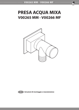
C-1500
IT Uso e Manutenzione
EN Operation and Maintenance
IT
DATI IDENTIFICATIVI
I dati identificativi e la marcatura “CE” della macchina sono posizionati sulla targhetta posta
sul corpo macchina.
Si consiglia di trascrivere il modello della macchina e il relativo numero di matricola nella tabella riportata nella pagina seguente.
EN
IDENTIFICATION DATA
The machine identification data and “CE” marking are located on the plate on the machine
body.
It is advisable to note the machine model and serial number on the table on the next page.
0-2
0-3
1
2
iPX4
7
6
Single Disc
.............. V ......... Hz
......... W
Mod: ..................
Nr . ...........................
Working Ø: ..........mm
Art.: .................
Speed: .... rpm
MADE IN ITALY
1
2
3
4
5
6
7
Ø di lavoro
Velocità di
rotazione
N° Matricola
Caratteristiche
elettriche
Working Ø
Rotation
speed
Serial number
Electrical
characteristics
IT
Produttore
Modello
Codice
Articolo
EN
Manufacturer
Model
Article code
0-4
3
4
5
4
Fig. 2
Fig. 1
Fig. 3
3
5
2
Fig. 7
1
6
Fig. 4
11
Fig. 5
8
12
Fig. 8
7
Fig. 6
14
9
13
15
14
10
Fig. 9
13
13
14
13
14
Fig. 10
17
16
0-5
Fig. 11
Fig. 13
Fig. 12
21
24
18
18
20
26
22
31
Fig. 15
29
19
Fig. 14
23
20
18
27
26
28
33
Fig. 16
20
23
Fig. 18
36
37
30
Fig. 17
28
32
1
30
2
34
3
Fig. 19
35
38
37
34
34
34
39
0-6
Fig. 21
52
44
54
53
42
41
42
49
43
55
Fig. 20
41
40
48
51
46
45
46
45
47
50
0-7
Fig. 22
Fig. 23
57
56
57
Fig. 24
58
59
Fig. 25
0-8
60
IT
Italiano.............................................................. I -1
(Istruzioni originali)
EN
English.......................................................... EN -1
(Translation of original instructions)
.
.
.
.
.
.
.
0-9
IT
Gentile cliente,
La ringraziamo per aver scelto un nostro prodotto per la pulizia dei suoi ambienti.
La lucidatrice da lei acquistata è stata progettata per soddisfare l’utilizzatore in termini
di semplicità di utilizzo e affidabilità nel tempo.
Noi siamo coscienti che un buon prodotto per restare tale, nel tempo, necessita di continui aggiornamenti mirati a soddisfare le aspettative di chi, quotidianamente, ne fa
uso. In tal senso, noi ci auguriamo di avere in lei non solo un cliente soddisfatto ma
anche un partner che non esita a trasmetterci opinioni e idee derivanti dalla personale
quotidiana esperienza.
I-1
IT
Indice
1.1 - CARATTERISTICHE TECNICHE....................................................................I-3
1.2 - INTRODUZIONE..............................................................................................I-3
1.3 - USO PREVISTO DELLA MACCHINA.............................................................I-3
1.4 - USO NON PREVISTO DELLA MACCHINA....................................................I-3
2.1 - DISIMBALLO...................................................................................................I-4
2.2 - ASSEMBLAGGIO COMPONENTI..................................................................I-4
2.2.a -Montaggio supporti avvolgicavo....................................................................I-4
2.2.b -Montaggio pad..............................................................................................I-4
2.2.c -Montaggio accessorio Spray elettrico...........................................................I-4
2.2.d -Riempimento del serbatoio ..........................................................................I-4
2.2.e -Montaggio filtro in carta raccolta polvere .....................................................I-4
2.2.f - Collegamento elettrico..................................................................................I-5
3.1 CONOSCENZA DELLA MACCHINA.................................................................I-5
4.1 REGOLAZIONE INCLINAZIONE MANIGLIONE...............................................I-5
5.1 MANIGLIONE GUIDA........................................................................................I-6
6.1 FUNZIONAMENTO ...........................................................................................I-6
6.1.a -Controlli prima dell’uso..................................................................................I-6
6.1.b -Avviamento macchina ..................................................................................I-6
6.1.c -Regolazione pressione pad . ........................................................................I-6
6.1.d -Uso della macchina.......................................................................................I-7
6.1.e -Fine uso e spegnimento ...............................................................................I-7
6.1.f - Trasporto ......................................................................................................I-7
6.1.g -Posizionamento macchina dopo l’uso...........................................................I-7
7.1 MANUTENZIONE E PULIZIA ...........................................................................I-8
7.1.a -Pulizia macchina...........................................................................................I-8
7.1.b -Pulizia ugello accessorio Spray (Optional) . .................................................I-8
7.1.c -Sostituzione pad............................................................................................I-8
PROBLEMI - CAUSE - RIMEDI...............................................................................I-9
I-2
IT
1.1 CARATTERISTICHE
TECNICHE
1.3 - USO PREVISTO DELLA
MACCHINA
La macchina è stata progettata e costruita:
per la lucidatura di pavimenti preventivamente puliti ed aspirati (ad esempio parquet,
marmo, ceramica, linoleum, ecc.).
C-1500
Tensione
Frequenza
Potenza motore
Pista di lavoro
Velocità di
rotazione
230 V
50Hz
1300W
1500 giri/min.
Peso senza
accessori
44 Kg
Lunghezza cavo
elettrico
15 m
Livello sonoro
Livello vibrazioni
PERICOLO:
Qualsiasi altro utilizzo solleva il costruttore da responsabilità per danni a persone
e/o cose e fa decadere qualsiasi condizione di garanzia.
505 mm - 20 inch.
1.4 - USO NON PREVISTO
DELLA MACCHINA
< 70 db(A)
< 2.5
Pressione di
lavoro
0÷5 Kg (regolabile)
Tipo di
trasmissione
diretta
Dimensioni
massime
1130x790x330H mm
Dimensioni
minime
855x790x485H mm
AVVERTENZA:
La macchina non è destinata a funzionare
all’aperto.
PERICOLO:
non lucidare pavimenti sconnessi;
non utilizzare su pavimenti in cemento;
non utilizzare su pavimenti sporchi;
non utilizzare gasolio/benzine o detergenti corrosivi per la lucidatura di pavimenti;
- non lucidare in presenza di liquidi corrosivi, infiammabili, esplosivi anche se diluiti.
-
-
-
-
1.2 INTRODUZIONE
PERICOLO:
Prima di utilizzare l’apparecchio leggere attentamente il libretto “AVVERTENZE DI SICUREZZA PER MONOSPAZZOLE” allegato
al presente.
2.1 DISIMBALLO (Figg. 1-2)
Al ricevimento della macchina rimuovere
l’imballo esterno, quindi tagliare le regge (1)
(Fig. 1) e sollevare il maniglione (2) tirando la
maniglia di sblocco (3) (Fig. 2).
Il presente manuale costituisce parte integrante della macchina stessa; deve essere pertanto conservato con cura in un luogo sicuro e
accessibile a tutti gli utilizzatori (operatori e
personale addetto alla manutenzione) per tutta la vita della macchina fino alla demolizione.
I-3
IT
2.2 ASSEMBLAGGIO
COMPONENTI
2.2.a - Montaggio supporti
avvolgicavo (Figg. 3/5)
I supporti avvolgicavo in dotazione vanno
montati direttamente sull’asta del maniglione:
- Incastrare l’innesto corto (4) nell’innesto
lungo (5) (Fig. 3).
- Avvitare il pomello (6) sulla vite (7) mantenendo quest’ultimo verso destra (Fig.
4).
- Il gancio (8) del supporto può essere ruotato a seconda dell’utilizzo (Fig. 5).
- Posizionare un supporto nella parte superiore del maniglione e un secondo supporto in quella inferiore.
2.2.b - Montaggio pad (Figg. 6/9)
- Ribaltare la macchina facendo perno, a
manico dritto (9), con il piede sulle ruote
(10) e deporla sull’impugnatura (Fig. 6).
- Svitare la ghiera (11) tramite l’apposita
maniglia (12) in dotazione (Fig. 7).
- Montare il pad (13) sul disco trascinatore
(14) (Fig. 9).
- Centrare il pad (13) con la guida centrale (15) sul disco trascinatore (14) e assicurarsi che il perimetro esterno del pad
(13) corrisponda con il perimetro esterno
del disco trascinatore (14) e bloccarlo sui
dentini del trascinatore premendo con le
dita (Figg. 8-9).
- Utilizzare il pad per la lucidatura ad alta
velocità (tipo Gorilla o Colore Cream).
AVVERTENZA:
Utilizzare solo pad forniti dal costruttore
relativi al modello di macchina.
L’utilizzo di altri tipi di pad può compromettere la sicurezza della macchina.
2.2.c - Montaggio accessorio Spray
elettrico (Optional)
(Figg. 10/16)
- Allentare il pomello (16) del supporto superiore (17) del maniglione, (Fig. 10).
- Assicurarsi che il supporto inferiore (18)
appoggi sulla piastrina (19) posizionata
sull’asta del maniglione (Fig.11).
- Posizionare l’accessorio (20) sul supporto inferiore (18), facendo attenzione a far
combaciare la linguetta di incastro (21)
con l’apposita sede (22) (Fig. 12).
- Abbassare l’innesto superiore (23) ed
agganciarlo alla linguetta di incastro (24)
posta sulla parte superiore dell’accessorio (20) (Fig.13).
- Avvitare il pomello (26) del supporto superiore (23) del maniglione (Fig. 13).
- Collegare l’alimentazione elettrica (26)
alla presa ausiliaria (27) (Fig. 14).
- Montare l’ugello (28) sulla parte destra
della macchina inserendo la piastrina
(33) all’interno del carter (29) e la vite
del pomello (30) nell’apposita cava (31),
quindi avvitare il pomello (30) (Fig. 15).
- Controllare che l’ugello (32) sia in posizione orizzontale. L’angolo di spruzzo è
120°; è possibile regolare la posizione
dell’ugello in funzione alle esigenze (Fig.
16).
2.2.d - Riempimento del serbatoio
(Fig. 17)
- Svitare il serbatoio (34) e rimuoverlo.
- Riempirlo con acqua e cera.
Per il dosaggio vedi istruzioni del produttore della cera.
- Inserire il tubo di pescaggio (35) nel serbatoio (34) e avvitare fino a finecorsa.
2.2.e - Montaggio filtro in carta
raccolta polvere (Figg. 18/19)
La macchina arriva con il sacchetto già montato.
- Sollevare lo sportello (36) e controllare
che il sacchetto (37) sia posizionato correttamente (Fig. 18).
I-4
IT
46)
47)
48)
49)
50)
51)
52)
53)
Ruote
Ruota anteriore pivottante
Cavo alimentazione elettrica
Presa ausiliaria
Manopola regolazione pressione pad
Sportello accesso sacchetto
Pulsante avviamento spruzzo cera
Led rosso: quando si illumina e rimane
illuminato indica una eccessiva pressione del pad sul pavimento.
(Pericolo di surriscaldamento pavimento
con coseguente bruciatura dello stesso)
54) Led verde: illuminato indica che la pressione del pad sul pavimento è corretta.
55) Relè termico motore: si inserisce bloccando il funzionamento del motore
quando la macchina lavora con un carico eccessivo.
Per riarmare la termica attendere qualche minuto che il motore si raffreddi
quindi premere il pulsantino per riarmarlo.
- Se il sacchetto non è presente, per montarlo, dopo aver sollevato lo sportellino
(36), inserire nel foro (38) del sacchetto (37) il tubo (39) di aspirazione (Fig.
18-19).
- Chiudere lo sportellino (36) che viene
mantenuto in posizione da una calamita
(Fig 18).
2.2.f - Collegamento elettrico
- Collegare il cavo di alimentazione della
macchina ad una presa di rete avente
caratteristiche corrispondenti a quelle riportate sulla targa dati tecnici della macchina.
AVVERTENZA:
- Accertarsi che l’impianto elettrico di
rete sia provvisto di interruttore differenziale (tipo salvavita) e di messa a
terra.
- Svolgere completamente il cavo di alimentazione elettrica prima di mettere in
funzione l’apparecchio.
- Utilizzare una prolunga elettrica solo
se in perfetto stato; assicurarsi che la
sezione sia appropriata alla potenza
dell’apparecchio.
- Non lasciare mai scorrere il cavo di alimentazione su spigoli taglienti ed evitare di schiacciarlo.
- La presa di corrente deve essere di facile accesso.
- Assicurarsi che il cavo elettrico non sia
danneggiato.
4.1 REGOLAZIONE
INCLINAZIONE
MANIGLIONE (Figg. 20-21)
AVVERTENZA:
La regolazione della posizione del maniglione va effettuata a macchina ferma.
- Tirando la leva (43) è possibile variare la
posizione del maniglione (40);
rilasciando la leva il maniglione si posiziona e si blocca nella posizione obbligata più vicina.
3.1 CONOSCENZA DELLA
MACCHINA (Figg. 20-21)
40)
41)
42)
43)
44)
45)
NOTA:
Regolare il maniglione in una posizione comoda, in funzione della propria altezza, in
modo da spingere agevolmente la macchina
per percorsi rettilinei.
Non avviare mai la macchina senza aver reclinato in modo corretto il maniglione.
Maniglione guida
Scatola comandi elettrici
Leve avviamento rotazione pad
(on-off)
Leva inclinazione maniglione
Pulsante sblocco leve rotazione pad
Corpo macchina
I-5
IT
5.1 MANIGLIONE GUIDA
(Fig. 21)
1) Pulsante sblocco leve rotazione pad
(44)
Premere il pulsante (44) per sbloccare le
leve avviamento rotazione pad (42).
2) Leve avviamento rotazione pad (42)
Tirando le leve rotazione pad (42) si abilita la rotazione del pad.
Al rilascio delle leve (42) la rotazione del
pad si interrompe e la macchina si ferma
automaticamente.
Le leve (42) vanno mantenute tirate per
ottenere il continuo funzionamento della
macchina.
3) Pulsante spruzzo liquido lucidatura
(52)
Premendo il pulsante e mantenendolo
premuto si avvia lo spruzzo liquido lucidatura; rilasciando il pulsante lo spruzzo
si ferma.
NOTA:
Lo spruzzo funziona anche quando il pad non
ruota.
6.1 FUNZIONAMENTO
6.1.a - Controlli prima dell’uso
- In presenza di accessorio spray elettrico montato (Optional) controllare che lo
stesso contenga liquido di lucidatura sufficiente alla fase di lavoro e che l’ugello
sia correttamente montato e regolato.
- Controllare le condizioni del pad.
Se usurato, sostituirlo.
- Controllare che l’apparecchio, in particolare il cavo di rete, non presenti danni
che possano compromettere il corretto
funzionamento della macchina o la sicurezza dell’operatore.
6.1.b - Avviamento macchina
(Fig. 21)
AVVERTENZA:
Non avviare la macchina in posizione ribaltata.
non avviare la macchina senza il pad correttamente montato.
NOTA:
La macchina non parte se l’asta del maniglione
è in posizione verticale.
PERICOLO:
Lavorare esclusivamente con mani asciutte.
- Tirare verso l’alto la leva (43) ed abbassare il maniglione fino a portarlo all’altezza desiderata.
- Premere il pulsante (44) per sbloccare le
leve avviamento rotazione pad (42).
- Tirando le leve (42) la macchina si avvia.
- Al rilascio di entrambe le leve (42) la
macchina si ferma.
AVVERTENZA:
Non avvolgere mai il cavo di rete intorno
al collo o al corpo macchina.
6.1.c - Regolazione pressione pad
(Fig. 22)
- Ruotare il volantino (56) in senso antiorario fino a finecorsa (il pad si solleva).
- Avviare la rotazione della spazzola, si illumina il led verde.
- Mantenere con la mano sinistra la leva
premuta e con la mano destra ruotare in
senso orario il volantino, fino a che il led
rosso si illumini, poi ruotare in senso antiorario fino a riportare il led verde illuminato.
- Il funzionamento corretto è quando l’illuminazione oscilla tra il led rosso e il led
verde.
I-6
IT
- L’uso dell’accessorio Spray (opzionale)
con prodotto chimico adatto permetterà
anche di eliminare gli eventuali segni sulla cera.
- Ruotando il volantino (56) in senso orario
la macchina si abbassa aumentando la
pressione sul pad.
Ruotando il volantino (56) in senso antiorario la macchina si solleva diminuendo
la pressione sul pad.
NOTA:
Utilizzare la macchina ferma con rotazione pad
inserita per un tempo prolungato può causare
danni al pavimento.
AVVERTENZA:
Se durante il funzionamento la spia rossa
si illumina fissa è necessario diminuire la
pressione sul pad agendo sul volantino;
non utilizzare la macchina con la spia rossa illuminata fissa, il pavimento si potrebbe rovinare.
NOTA:
Rilasciando le leve (42) la rotazione del pad si
ferma e la macchina si spegne.
6.1.e - Fine uso e spegnimento
(Fig. 21 e 23)
6.1.d - Uso della macchina
(Fig. 21)
- Rilasciare le leve (42) per arrestare la rotazione del pad e spegnere la macchina
(Fig. 21).
- Posizionare verticalmente il maniglione.
- Togliere il serbatoio (Optional) e svuotarlo dalla soluzione ed effettuare l’operazione di pulizia ugello come indicato nel
paragrafo manutenzione.
- Dopo aver avviato la macchina iniziare le
operazioni di lucidatura tenendo premute
le leve (42), mantenendo cosi la macchina in funzione e la rotazione della spazzola attiva.
- La macchina lavora su piste di lavoro rettilinee: è quindi conveniente nel trattare
una superficie, iniziare dalle zone perimetrali lasciando per ultime le zone centrali. Lucidare camminando in linea retta
davanti a sè fino a dove lo consentono
il cavo di alimentazione o le dimensioni
della stanza, e ritornare pulendo una striscia parallela, avendo cura di non lasciare vuoti.
AVVERTENZA:
Non lasciare la macchina ferma con pad
montato e non sollevato per evitare la compromissione dello stesso.
- Staccare il cavo di alimentazione elettrica
dalla presa e avvolgerlo agli appositi supporti avvoglicavo.
- Arrotolare il cavo elettrico sui supporti
(57) (Fig. 23).
- Per togliere il cavo dai supporti ruotare i
ganci (58) verso l’interno e togliere il cavo
senza necessariamente svolgerlo (Fig.
24).
PERICOLO:
Evitare assolutamente durante il lavoro di
passare con la macchina sopra il cavo di
alimentazione: ciò provocherebbe gravi
danni e situazioni di pericolo!
- Inoltre la macchina è dotata di un sistema
passivo di aspirazione, atto a convogliare
il pulviscolo che si genera durante la lucidatura in un pratico filtro in carta a perdere, inserito nella parte anteriore della
stessa.
6.1.f - Trasporto
Con spina di rete scollegata e maniglione in
posizione verticale, sollevare il corpo macchina ruotando verso il basso il maniglione.
La macchina può essere così trasportata sulle ruote.
I-7
IT
6.1.g - Posizionamento macchina
dopo l’uso (Fig. 22 e 25)
Dopo l’uso della macchina è possibile rimessare la stessa in due modi:
Posizione verticale con pad appoggiato
(Fig. 22)
Posizionare il maniglione in posizione verticale quindi agire sul volantino (56) ruotandolo in senso antiorario fino a finecorsa in modo
da sollevare da terra il pad.
Posizione ribaltata (Fig. 25)
Caricare sul manico la macchina come se si
dovesse sostituire il pad.
Sollevare il maniglione fino a finecorsa.
La macchina rimane in posizione stabile,
appoggiando sulle ruote (60) e sul supporto
(59).
7.1 MANUTENZIONE E
PULIZIA
AVVERTENZA:
Per le informazioni e le avvertenze relative
alle operazioni di manutenzione o pulizia
attenersi a quanto indicato nel manuale
“Avvertenze di sicurezza per monospazzola” allegato al presente.
OPERAZIONI DA
EFFETTUARSI OGNI
GIORNO
7.1.a - Pulizia macchina
Effettuare la pulizia della macchina con un
panno umido e strofinare successivamente
con un panno asciutto e pulito onde evitare la
formazione di incrostazioni dovute all’effetto
dei prodotti chimici.
AVVERTENZA:
Non utilizzare solventi, acidi o sostanze
corrosive per la pulizia della macchina.
Se il pad risulta sporco, lavarlo ad una
temperatura massima di 60°.
7.1.b - Pulizia ugello accessorio
Spray (Optional)
(Figg. 21 e 17)
AVVERTENZA:
Alla fine delle operazioni di lucidatura è
obbligatorio scaricare e pulire il serbatoio
dell’acqua per evitare depositi o incrostazioni e pulire l’ugello.
- Rimuovere il serbatoio (34) (Fig. 17),
svuotare la soluzione, risciacquarlo e riempirlo di acqua.
- Posizionarsi con la macchina vicino ad
una piletta di scarcio e premere il pulsante (52) (Fig. 21) fino a svuotare il serbatoio.
OPERAZIONI DA
EFFETTUARSI SECONDO
NECESSITÀ
7.1.c - Sostituzione pad
Si rende necessaria la sostituzione del pad
quando lo stesso si presenta usurato con
uno spessore inferiore ai 10 mm;
per la sostituzione, vedere paragrafo “Montaggio pad”.
AVVERTENZA:
Utilizzare pad con diametro di 20’’
505 mm Tipo UHS.
I-8
IT
PROBLEMI - CAUSE - RIMEDI
PROBLEMA
CAUSA
Premendo il pulsante sbloc- Spina scollegata.
co leve contemporaneamente alle leve rotazione
spazzola la macchina non
si avvia.
RIMEDIO
Collegare la spina.
Il disco trascinatore non Leva rotazione spazzola/ Premere la leva.
ruota.
trascinatore non premuta.
Presenza di eventuali corpi
estranei.
Non fuoriesce soluzione lu- Serbatoio vuoto.
cidante.
Pulsante non premuto.
Rimuovere i corpi estranei
incastrati.
Riempire il serbatoio.
Premere il pulsante.
Lucidatura pavimento insuf- Pad o prodotto chimico ina- Usare pad o prodotto chimificiente.
deguati.
co adatti al tipo di pavimento da lucidare.
Pad consumato.
La macchina funziona in Controllare che il pad sia
modo irregolare o vibra for- perfettamente centrato al
temente.
disco trascinatore.
Pad non idoneo al tipo di
pavimento.
La macchina si spegne im- Inserimento protezione
provvisamente durante il termica motore.
lavoro.
I-9
Sostituire il pad.
Riposizionare il pad centrandolo correttamente al
disco trascinatore.
Utilizzare un pad idoneo
al tipo di superficie da
lucidare.
Ripristinare il pulsante
reset fino al “Click” e
assicurarsi di lavorare nel
range corretto.
EN
Dear Customer,
Thank you for choosing one of our cleaning products.
The floor polisher you have purchased has been designed to satisfy users in terms of
ease of use and reliability.
We are aware that, in order to remain so over time, a good product requires continuous updates aimed at satisfying the expectations of those who use it daily. To this end,
we hope that you will be not only a satisfied customer but also a partner who does not
hesitate to let us know your views and ideas resulting from personal experience on a
day-to-day basis.
EN - 1
EN
IT
Contents
1.1 - TECHNICAL CHARACTERISTICS.................................................................I-3
1.2 - INTRODUCTION..............................................................................................I-3
1.3 - INTENDED MACHINE USE............................................................................ I-3
1.4 - NON-INTENDED MACHINE USE ..................................................................I-3
2.1 - UNPACKING....................................................................................................I-4
2.2 - COMPONENT ASSEMBLY.............................................................................I-4
2.2.a - Assembling the cable reel supports .............................................................I-4
2.2.b -Pad assembly................................................................................................I-4
2.2.c -Electric spray accessory assembly...............................................................I-4
2.2.d -Filling the tank ..............................................................................................I-4
2.2.e -Paper dust collection filter assembly ............................................................I-4
2.2.f -Electrical Connection....................................................................................I-5
3.1 KNOWLEDGE OF THE MACHINE....................................................................I-5
4.1 HANDLE TILT ADJUSTMENT...........................................................................I-5
5.1 GUIDE HANDLE................................................................................................I-6
6.1 OPERATION .....................................................................................................I-6
6.1.a -Checks to be performed before use..............................................................I-6
6.1.b -Starting up the machine ...............................................................................I-6
6.1.c -Pad pressure adjustment .............................................................................I-6
6.1.d -Using the machine........................................................................................I-7
6.1.e -End of use and shutdown . ...........................................................................I-7
6.1.f - Transport ......................................................................................................I-7
6.1.g -Positioning the machine after use.................................................................I-7
7.1 MAINTENANCE AND CLEANING ...................................................................I-8
7.1.a -Cleaning the machine...................................................................................I-8
7.1.b -Cleaning the spray accessory nozzle (Optional) ..........................................I-8
7.1.c -Pad replacement...........................................................................................I-8
PROBLEMS - CAUSES - SOLUTIONS...................................................................I-9
EN - 2
EN
1.1 TECHNICAL
CHARACTERISTICS
1.3 - INTENDED USE OF
THE MACHINE
The machine has been designed and built:
for polishing floors that have been cleaned
and vacuumed beforehand (i.e. parquet,
marble, ceramic, linoleum etc.).
C-1500
Voltage
Frequency
Motor power
230 V
50Hz
1300W
Working width
505 mm - 20 inch.
Rotation speed
1500 rpm
Weight without
accessories
44 Kg
Electrical cable
length
15 m
Sound level
Vibration level
DANGER:
Any other use releases the manufacturer
from liability for harm to persons and/or
property and invalidates any warranty
condition.
1.4 - NON-INTENDED USE
OF THE MACHINE
< 70 db(A)
< 2.5
Working pressure
0÷5 Kg (adjustable)
Transmission type
direct
Maximum dimensions
1130x790x330H mm
Minimum dimensions
855x790x485H mm
WARNING:
The machine is not intended for outdoor
use.
1.2 INTRODUCTION
DANGER:
Before using the appliance, read the accompanying “SINGLE DISC SAFETY WARNINGS”
booklet carefully.
This manual forms an integral part of the machine itself. It must therefore be kept in a safe
place where it is accessible to all users (operators and maintenance personnel) throughout
the life of the machine until it is scrapped.
DANGER:
do not polish uneven floors;
do not use on cement floors;
do not use on dirty floors;
do not use diesel/petrol or corrosive detergents to polish floors;
- do not polish if corrosive, flammable and/
or explosive liquids, even if diluted, are
present.
-
-
-
-
2.1 UNPACKING (Figs. 1-2)
Upon delivery of the machine, remove its external packaging and cut the straps (1) (Fig.
1) and lift up the handle (2) by pulling on the
release handle (3) (Fig. 2).
EN - 3
EN
IT
2.2
COMPONENT
ASSEMBLY
2.2.c - Electrical spray accessory
assembly (Optional)
(Figs. 10/16)
2.2.a - Assembling the cable reel
supports (Figs. 3/5)
The reel supports supplied must be mounted
directly on the handle shaft:
- Fit the short coupling (4) into the long
coupling (5) (Fig. 3).
- Tighten the knob (6) on the screw (7),
keeping the latter to the right (Fig. 4).
- The hook (8) of the support can be rotated depending on usage (Fig. 5).
- Place one support on the top of the handle and a second support on the bottom.
2.2.b - Pad assembly (Figs. 6/9)
- Tilt the machine, pivoting, with the handle
straight (9), with your feet on the wheels
(10) and place it on the handle (Fig. 6).
- Unscrew the ring nut (11) using the handle (12) supplied (Fig. 7).
- Mount the pad (13) on the pad holder
(14) (Fig. 9).
- Centre the pad (13) with the central guide
(15) on the pad holder (14) and make
sure the outer perimeter of the pad (13)
corresponds with the outer perimeter of
the pad holder (14) and then lock it on
the pad holder’s teeth pressing down with
your fingers (Figs. 8-9).
- Use the pad for high-speed polishing
(Gorilla or Cream Colour).
WARNING:
Use only pads supplied by the manufacturer for the specific machine model.
Using other types of pads can compromise the safety of the machine.
- Loosen the knob (16) of the handle’s upper support (17) (Fig. 10).
- Make sure that the lower support (18)
rests on the plate (19) located on the handle rod (Fig. 11).
- Place the accessory (20) on the lower
support (18), taking care to align the coupling tab (21) with its housing (22) (Fig.
12).
- Lower the upper coupling (23) and attach
it to the coupling tab (24) on the top of the
accessory (20) (Fig. 13).
- Tighten the knob (26) of the handle’s upper support (23) (Fig. 13).
- Connect the power supply (26) to the
auxiliary socket (27) (Fig. 14).
- Fit the nozzle (28) on the right part of the
machine, inserting the plate (33) inside
the casing (29) and the knob screw in the
dedicated (30) housing (31), then tighten
the knob (30) (Fig. 15).
- Make sure the nozzle (32) is in the horizontal position. The spray angle is 120
degrees, the nozzle position may be
adjusted depending on specific requirements (Fig. 16).
2.2.d - Filling the tank (Fig. 17)
- Unscrew the tank (34) and remove it.
- Fill it with water and polishing wax.
For dosing, refer to the instructions provided by the manufacturer of the polishing wax.
- Insert the suction tube (35) into the tank
(34) and fully tighten.
2.2.e - Paper dust collection bag assembly (Figs. 18/19)
The machine is delivered with the bag already mounted.
- Lift the lid (36) and check that the bag
(37) is correctly positioned (Fig. 18).
EN - 4
EN
- If the bag is not present, to mount it, after
having lifted the door (36), insert the suction tube (39) in the bag’s (37) hole (38)
(Fig. 18-19).
- Close the lid (36) which is held in position
with a magnet (Fig 18).
2.2.f - Electrical connection
- Connect the machine power cable to a
mains socket whose characteristics correspond to those shown on the machine’s
technical data plate.
WARNING:
- Make sure the mains electrical system
has a circuit breaker and has been
earthed.
- Unwind the power cable completely before turning on the appliance.
- Use an extension cord only if in perfect
condition and make sure the diameter
is appropriate for the power of the appliance.
- Never allow the power cable to slide
over sharp edges and do not crush it.
- The socket should be easily accessible.
- Make sure the electrical cable is not
damaged.
3.1 KNOWLEDGE OF THE
MACHINE (Figs. 20-21)
40) 41) 42) 43) 44) 45) 46) 47) 48) 49) Guide handle
Electrical control box
Pad rotation start levers
(on-off)
Handle tilt lever
Pad rotation lever release button
Machine body
Wheels
Pivoting front wheel
Power cable
Auxiliary socket
50) 51) 52) 53) Pad pressure adjustment knob
Bag access flap
Polishing wax spray start button
Red LED: when it lights up and stays lit,
there is an excessive pad pressure on
the floor.
(Risk of floor overheating with consequent floor burning)
54) Green LED: when lit the pad pressure
on the floor is correct.
55) Motor thermal relay: enabled blocking
motor operation when the machine operates with a excessive load.
To reset the thermal relay wait a few
minutes for the motor to cool and then
press the small button to activate the
monitor.
4.1 HANDLE TILT
ADJUSTMENT (Figs. 20-21)
WARNING:
The handle position must be adjusted
while the appliance is at a standstill.
- Pulling the lever (43) the handle position
can be adjusted (40);
when the lever is released, the handle is
positioned and locked in the closest position required.
NOTE:
Adjust the handle to a comfortable position,
depending on your height, in order to easily
push the machine in straight paths.
Never start the machine without having tilted
the handle correctly.
EN - 5
EN
IT
5.1 GUIDE HANDLE (Fig. 21)
1) Pad rotation lever release button (44)
Press the button (44) to release the pad
rotation start levers (42).
2) Pad rotation start levers (42)
Pulling the pad rotation levers (42) enables pad rotation.
When the levers (42) are released, pad
rotation stops and the machine stops automatically.
The levers (42) should be kept pulled to
achieve continuous machine operation.
3) Polishing liquid spray button (52)
When the button is pressed and held
down, the polishing liquid spray is activated; if the button is released, the spray
stops.
NOTE:
The spray works even when the pad is not rotating.
6.1 OPERATION
6.1.a - Checks to be performed
before use
- If the electrical spray accessory is
mounted (optional), check that it contains
enough polishing liquid for the working
phase and that the nozzle is properly
connected and adjusted.
- Check the condition of the pad.
If worn, replace it.
- Check that the appliance, particularly the
mains cable, is not damaged in any way
that might compromise correct machine
operation or the operator’s safety.
6.1.b - Starting the machine
(Fig. 21)
WARNING:
Do not start the machine if it is tilted.
Do not start the machine if the pad is not
correctly mounted.
NOTE:
The machine will not start if the handle shaft
is upright.
DANGER:
Ensure your hands are dry before using the
appliance.
- Pull the lever up (43) and lower the handle until it reaches the height desired.
- Press the button (44) to release the pad
rotation start levers (42).
- Pulling the levers (42) starts the machine.
- When both levers (42) are released, the
machine stops.
WARNING:
Never wrap the power cable around the
neck or body of the machine.
6.1.c - Pad pressure adjustment
(Fig. 22)
- Turn the handwheel (56) counter clockwise as far as possible (the pad is lifted
up).
- Start brush rotation, the green led lights
up.
- With your left hand keep the lever pressed
down and with your right hand, turn the
handwheel clockwise, until the red lied
lights up, then turn it counter clockwise
until the green led lights up.
- Correct operation is when the red and
green leds alternate.
EN - 6
EN
- By turning the handwheel (56) clockwise
the machine is lowered by increasing
pressure on the pad.
If the handwheel (56) is turned counter
clockwise, the machine is lifted, decreasing pressure on the pad.
WARNING:
If during operation the red led lights up
and remains lit (not flashing), you must
decrease pressure on the pad using the
handwheel: do not use the machine if the
red light is constant as the floor may be
damaged.
6.1.d - Using the machine
(Fig. 21)
- After starting the machine, begin polishing operations by keeping the levers (42)
pressed, thus keeping the machine running and brush rotation active.
- The machine operates on straight line
paths: it is therefore appropriate to treat a
surface, starting from the perimeter zones
while leaving the central areas for last.
Polish by walking in a forward straight
line up to where the cable length or room
size permits, and then return polishing a
parallel strip, making sure not to leave
any spaces unpolished.
DANGER:
During operation, avoid passing over the
power cable with the machine: this could
cause serious damage and dangerous
situations!
- The machine is also equipped with a passive aspiration system, designed to convey the fine dust generated during polishing to a convenient disposable paper
filter, in front of the same.
- Use of the Spray accessory (optional)
with a suitable chemical product will allow for removing any marks on the wax.
NOTE:
Using the machine in a fixed position with the
pad rotation enabled for a prolonged period of
time can cause damage to the floor.
NOTE:
When the levers (42) are released, pad rotation
stops and the machine turns off
6.1.e – End of use and shutdown
(Fig. 21 and 23).
- Release the levers (42) to stop pad rotation and turn off the machine (Fig. 21).
- Put the handle in an upright position.
- Remove the tank (Optional), empty the
solution and clean the nozzle as indicated in the maintenance paragraph.
WARNING:
Do not leave the machine stopped if the
pad is mounted and not raised in order to
prevent them from being damaged.
- Unplug the power cable from the socket
and wrap it around the cable reel supports.
- Roll up the cable on the supports (57)
(Fig. 23).
- To remove the cable from the supports,
turn the hooks (58) inward and remove
the cable without necessarily unwinding it
(Fig. 24).
6.1.f - Transport
Making sure that the mains plug is disconnected and the handle is in an upright position, lift the machine body by turning the handle downwards.
The machine can then be transported on the
wheels.
EN - 7
EN
IT
6.1.g - Positioning the machine after
use (Fig. 22 and 25).
After machine use, it can be stored in two
ways:
Upright position with pad resting on
ground (Fig. 22)
Place the handle in the upright position and
then turn the handwheel (56) counter clockwise as far as it will go in order to lift the pad
off the ground.
Upside down position (Fig. 25)
Load the machine on the handle as if you
were to replace the pad.
Fully raise the handle.
The machine remains in a stable position,
resting on the wheels (60) and the support
(59).
7.1 MAINTENANCE AND
CLEANING
WARNING:
For information and warnings relating
to maintenance or cleaning, follow what
is described in the “Safety warnings for
single disc” manual, accompanying this
document.
7.1.b - Cleaning the nozzle of the
spray accessory (Optional)
(Figs. 21 and 17).
WARNING:
Once you have finished polishing, you
must drain and clean the water tank to
prevent deposits or scaling and you must
clean the nozzle.
- Remove the tank (34) (Fig. 17), empty the
solution, rinse it and refill it with water.
- Position yourself with the machine near a
discharge drain and press the button (52)
(Fig. 21) until the tank is empty.
OPERATIONS TO BE
CARRIED OUT WHEN
NECESSARY
7.1.c - Pad replacement
The pad must be replaced when it is worn
and its thickness is less than 10 mm;
see the “Pad Assembly” paragraph for replacement instructions.
OPERATIONS TO BE
CARRIED OUT
DAILY
7.1.a - Cleaning the machine
WARNING:
Do not use solvents, acids or corrosive
substances for cleaning the machine.
If the pad is dirty, wash it at a maximum
temperature of 60 °.
Clean the machine with a damp cloth and
then wipe it with a clean, dry cloth to prevent
the formation of scale due to the effect of
chemicals.
WARNING:
Use a pad with a 20’’ diameter
505 mm Type UHS.
EN - 8
EN
TROUBLESHOOTING
PROBLEM
CAUSE
Although the lever release The appliance is
button and brush rotation unplugged.
levers are pressed at the
same time, the machine
does not start.
SOLUTION
Plug the appliance in.
The pad holder does not The brush/pad holder rota- Press the lever.
rotate.
tion lever is not pressed.
Presence of foreign bodies. Remove any foreign bodies
stuck in the appliance.
Polishing liquid is not re- The tank is empty.
leased.
Button not pressed.
Insufficient floor polishing.
Fill the tank.
Press the button.
Pad or chemical product Use a pad or chemical prodnot suitable.
uct that is appropriate to the
type of floor to be polished.
Pad worn.
The machine operates er- Check that the pad is
ratically or vibrates heavily. perfectly centred in the pad
holder.
Replace the pad.
Replace the pad, centring it
correctly in the pad holder.
Pad not suited to floor type. Use a pad suited to the
floor surface.
The machine turns off unex- Motor thermal protection
pectedly during operation.
activation.
EN - 9
Restore the reset button
until it "Clicks" and make
sure to work in the correct
range.
Cod.GA30-925 - 1^ ed. - 04/2015
DEALER
"GADLEE Green Cleaning Equipment Corp
7F, Block A8, Hantian Industrial Park,
Dongping Road, Nanhai District,
Foshan Guangdong 528200
Cina"
Scarica