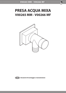
LISA - LIA
ISTRUZIONI PER L’INSTALLATORE
INSTRUCTIONS FOR THE INSTALLER
INSTRUCTIONS POUR L’INSTALLATEUR
AUFBAUANLEITUNG FÜR DEN INSTALLATEUR
H07027450 / DT2000891-01
Deutsch
Français
English
Italiano
Il libretto istruzioni è parte integrante del prodotto. - The instruction booklet is an integral part of the product. - Le manuel fait partie intégrante du produit. - Die Anleitung ist Bestandtel des Produktes
Set Scarico
Gas outlet set
Set départ des fumées
Rauchabzug-Set
1.0 PREFAZIONE
Italiano
DT2012492-00
4
3
6
5
1
2
DT2033706-0
DT2033706-00
Il prodotto è predisposto con l’uscita scarico fumi sulla parte destra. E’ comunque possibile optare, tra diverse
uscite, come indicato in figura:
1
2
3
4
5
6
SCARICO FUMI POSTERIORE DESTRO;
SCARICO FUMI LATERALE DESTRO;
SCARICO FUMI SUPERIORE DESTRO;
SCARICO FUMI SUPERIORE CENTRALE (*);
SCARICO FUMI POSTERIORE SINISTRO (**);
SCARICO FUMI LATERALE SINISTRO (**).
(*) = E’ consigliabile acquistare il SET SCARICO SUPERIORE CENTRALE.
Con questa configurazione non è possibile montare il SET RACCORDO CANALIZZAZIONE POSTERIORE.
(**) = E’ necessario acquistare il SET SCARICO SINISTRO.
2
H07027450 / DT2000891-01
DT2012493-00
Italiano
2.0 ESPLOSO SET SCARICO SUPERIORE CENTRALE
1
2
DT2033731-0
Nr.
1
2
Descrizione
Raccordo curvo centrale con ispezione
Tubo Ø 8 cm. L = 50 cm
H07027450 / DT2000891-01
Q.tà
1
1
3
Italiano
3.0 INSTALLAZIONE SCARICO FUMI SUPERIORE CENTRALE
- Rimuovere il pannello laterale destro e il piano
superiore in ceramica con i relativi coprifori, vedi
paragrafo “RIMOZIONE RIVESTIMENTO” del
libretto istruzioni allegato alla stufa.
- Rimuovere la copertura laterale destra [D]
svitando le 9 viti che la fissano. (Fig. 1)
DT2012494-00
Fig. 1
D
DT20033718-00
- Togliere il semitrancio [B] presente nella parte
inferiore della copertura laterale, prestando
attenzione a non graffiarla o deformarla. (Fig. 2)
Fig. 2
B
DT2033719-00
- Inserire il tubo Ø 8 cm e di lunghezza 50 cm
[2], in dotazione, nell’uscita libera del tubo scarico
fumi a “T” [G].
- Inserire il raccordo curvo con ispezione [1] nel
tubo appena posizionato. (Fig. 3)
- Riposizionare la copertura laterale destra [D]
procedendo nell’ordine inverso a quello eseguito
per lo smontaggio.
Fig. 3
1
2
G
DT2033732-0
4
H07027450 / DT2000891-01
Fig. 4
E
Italiano
- Togliere la vite presente sul tappo che chiude il
tubo a “T” e chiudere il foro presente sulla copertura
laterale destra con il tappo [E] fissandolo con la vite
[F] in dotazione. (Fig. 4)
F
DT2033712-0
DT2033712-01
- Proseguire con il montaggio del rivestimento
riposizionando il laterale, il piano superiore in
ceramica, inserendolo nel raccordo curvo con
ispezione appena posizionato, e il copriforo laterale
nella propria sede. (Fig. 5)
Fig. 5
Il copriforo centrale è a perdere.
- Procedere con il collegamento alla canna fumaria
rispettando le indicazioni del capitolo “NORME
GENERALI” presente nel libretto istruzioni della
stufa.
DT2033733-0
H07027450 / DT2000891-01
5
4.0 ESPLOSO SET SCARICO SINISTRO
Italiano
DT2012495-00
3
4
5
6
1
2
7
DT2033734-0
Nr.
1
2
3
4
5
6
7
6
Descrizione
Raccordo curvo sinistro
Elemento di tamponamento
Guarnizione
Vite M5x12
Rondella
Dado
Vite autofilettante
Q.tà
1
1
1
4
4
4
4
H07027450 / DT2000891-01
- Rimuovere i pannelli laterali e il piano superiore
in ceramica, con i relativi coprifori (vedi paragrafo
“RIMOZIONE RIVESTIMENTO” del libretto istruzioni
allegato alla stufa).
- Rimuovere il pannello posteriore svitando le 26
viti che lo sostengono (Fig. 1).
DT2012496-00
Italiano
5.0 INSTALLAZIONE SCARICO FUMI POSTERIORE SINISTRO
Fig. 1
DT2033735-00
- Rimuovere la copertura laterale sinistra [I]
svitando le 6 viti che la fissano (Fig. 2).
Fig. 2
I
DT2033736-0
- Togliere il semitrancio [B] presente nella parte
inferiore della copertura laterale prestando
attenzione a non graffiarla o deformarla. (Fig. 3)
Fig. 3
B
DT2033708-00
H07027450 / DT2000891-01
7
Italiano
- Rimuovere il ventilatore ambiente svitando le
quattro viti [A] che lo sostengono. Per estrarlo
dalla stufa, ruotare il motore come in figura a lato,
facendo attenzione a non danneggiarlo. (Fig. 4)
Fig. 4
A
VISTA DI LATO
DT2033737-0
- Rimuovere il convogliatore dell’aria nella parte
posteriore della stufa, svitando le 4 viti [G] che lo
sostengono (Fig. 5).
Fig. 5
G
- Togliere le 3 viti M6x25 e le relative rondelle
che sostengono il ventilatore estrazione fumi e
poggiarlo sul basamento della stufa (Fig. 6).
DT2033738-0
Fig. 6
DT2033739-0
8
H07027450 / DT2000891-01
Fig. 7
Italiano
- Rimuovere il tubo scarico fumi a T, rimuovendo
le quattro viti [H] che lo fissano al raccordo
flangiato (Fig. 7).
H
DT2033740-0
- Ruotare di circa 180° il ventilatore estrazione
fumi e fissarlo sul fondo della stufa con le viti
M6x25 e le rondelle tolte in precedenza, come
schematizzato in figura 8.
Fig. 8
1
Montando il ventilatore estrazione fumi
con la bocca girata verso sinistra, le
sedi per le viti e le rondelle risulteranno
diverse dal precedente fissaggio.
2
DT2033742-0
- Fissare il raccordo curvo sinistro [1] presente nel
SET con le quattro viti [H] precedentemente tolte.
Fare attenzione a non schiacciare o rovinare la
guarnizione.
- Posizionare la guarnizione [3] in dotazione sul
raccordo curvo sinistro appena fissato e bloccare
il tubo scarico fumi a “T” con le 4 viti M5x12 [4], le
rondelle [5] e i dadi [6] in dotazione.
- Girare la bocca libera del tubo a “T” verso la
parte posteriore della stufa (Fig. 9).
- Verificare il centraggio del tubo scarico fumi a
“T” con il foro presente nel pannello posteriore.
- Riposizionare il convogliatore dell’aria [M] e il
ventilatore ambiente [L] procedendo nell’ordine
inverso a quanto eseguito per lo smontaggio.
(Fig. 10).
Fig. 9
4
5
6
1
H
3
DT2033743-0
Fig. 10
M L
DT2033747-0
H07027450 / DT2000891-01
9
Italiano
- Fissare l’elemento di tamponamento [2] nella
parte posteriore bassa della stufa con le viti
autofilettanti [7] in dotazione (Fig. 11).
Fig. 11
7
2
DT2033744-0
- Dal pannello posteriore, precedentemente
rimosso, togliere il semitrancio [C] prestando
attenzione a non deformare il pannello (Fig. 12).
Fig. 12
C
DT2033741-0
- Riposizionare la copertura laterale sinistra [I]
procedendo nell’ordine inverso a quello eseguito
per lo smontaggio.
- Togliere la vite presente sul tappo che chiude il
tubo a “T”. Chiudere il foro presente sulla copertura
laterale destra con il tappo [E] fissandolo con la
vite [F] in dotazione. (Fig. 13)
- Riposizionare il pannello posteriore procedendo
nell’ordine inverso a quanto eseguito per lo
smontaggio.
- Procedere al collegamento alla canna fumaria
rispettando le indicazioni del capitolo “NORME
GENERALI” presente nel libretto istruzioni della
stufa.
- Completare il montaggio del rivestimento.
10
Fig. 13
H07027450 / DT2000891-01
I
F
E
DT2033745-0
- Rimuovere il pannello laterale destro e il piano
superiore in ceramica con i relativi coprifori, vedi
paragrafo “RIMOZIONE RIVESTIMENTO” del
libretto istruzioni allegato alla stufa.
- Rimuovere il pannello posteriore svitando le 26 viti
che lo sostengono (Fig. 1).
DT2012497-00
Italiano
6.0 INSTALLAZIONE SCARICO FUMI LATERALE SINISTRO
Fig. 1
DT2033735-00
- Rimuovere la copertura laterale sinistra [I]
svitando le 6 viti che la fissano (Fig. 2);
Fig. 2
I
DT2033736-0
- Togliere il semitrancio [B] presente nella parte
inferiore della copertura laterale prestando
attenzione a non graffiarla o deformarla. (Fig. 3)
- Applicare al foro della copertura, la guarnizione
copribordo [C] in dotazione, tagliando l’eventuale
lunghezza eccedente.
- Bloccare la guarnizione con alcune gocce di
silicone adatto alle alte temperature.
Fig. 3
C
B
DT2033708-00
DT2033708-0
H07027450 / DT2000891-01
11
Italiano
- Rimuovere il ventilatore ambiente svitando le
quattro viti [A] che lo sostengono.
Per estrarlo dalla stufa, ruotare il motore come
rappresentato a lato facendo attenzione a non
danneggiarlo. (Fig. 4)
Fig. 4
A
VISTA DI LATO
DT2033737-0
- Rimuovere il convogliatore dell’aria nella parte
posteriore della stufa, svitando le quattro viti [G]
che lo sostengono (Fig. 5).
Fig. 5
G
- Togliere le tre viti M6x25 e le relative rondelle
che sostengono il ventilatore estrazione fumi e
poggiarlo sul basamento della stufa (Fig. 6)
DT2033738-0
Fig. 6
DT2033739-0
12
H07027450 / DT2000891-01
Fig. 7
Italiano
- Rimuovere il tubo scarico fumi a T, rimuovendo
le quattro viti [H] che lo fissano al raccordo
flangiato (Fig. 7).
H
DT2033740-0
- Ruotare di circa 180° il ventilatore estrazione
fumi e fissarlo sul fondo della stufa con le viti
M6x25 e le rondelle tolte in precedenza. (Fig. 8)
Fig. 8
1
Montando il ventilatore estrazione fumi
con la bocca girata verso sinistra le
sedi per le viti e le rondelle risulteranno
diverse dal precedente fissaggio.
2
DT2033742-0
- Fissare il raccordo curvo sinistro [1] presente nel
SET con le quattro viti [H] precedentemente tolte.
Fare attenzione a non schiacciare o rovinare la
guarnizione.
- Posizionare la guarnizione [3] in dotazione sul
raccordo curvo sinistro appena posizionato e
fissare il tubo scarico fumi a T con le quattro viti
M5x12 [4], le rondelle [5] e i dadi [6] in dotazione.
(Fig. 9)
Fig. 9
4
5
3
6
1
H
DT2033746-0
- Togliere il tappo e la guarnizione presenti sul tubo
scarico fumi a “T” svitando le 2 viti che la fissano.
Posizionarli sull’altra uscita del tubo, fissandoli
con le viti appena rimosse. (Fig. 10)
Fig. 10
DT2033748-0
H07027450 / DT2000891-01
13
Italiano
- Riposizionare il convogliatore dell’aria [M] e il
ventilatore ambiente [L] procedendo nell’ordine
inverso a quanto eseguito per lo smontaggio.
(Fig. 11)
Fig. 11
M L
DT2033747-0
- Fissare l’elemento di tamponamento [2] nella
parte posteriore bassa della stufa con le viti
autofilettanti [7] in dotazione (Fig. 12).
Fig. 12
- Riposizionare la copertura laterale sinistra [I]
e il pannello posteriore, procedendo nell’ordine
inverso a quello eseguito per lo smontaggio.
- Procedere al collegamento alla canna fumaria
rispettando le indicazioni del capitolo “NORME
GENERALI” presente nel libretto istruzioni allegato
alla stufa.
In caso di installazione con scarico
fumi laterale la distanza MINIMA del
tubo scarico fumi dalla stufa è indicato
nel paragrafo “DISTANZE MINIME
DI SICUREZZA” presente nel libretto
istruzioni allegato alla stufa.
- Completare il montaggio del rivestimento.
14
H07027450 / DT2000891-01
7
2
DT2033744-0
H07027450 / DT2000891-01
15
1.0 PREFACE
DT2012492-00
4
English
3
6
5
2
1
DT2033706-0
The product leaves the factory with flue gas outlet on the right side.
There is, however, the option of various outlet positions, as shown in the figure:
1 RIGHT REAR FLUE GAS OUTLET;
2 RIGHT SIDE FLUE GAS OUTLET;
3 RIGHT TOP FLUE GAS OUTLET;
4 CENTRAL TOP FLUE GAS OUTLET (*);
5 LEFT REAR FLUE GAS OUTLET (**);
6 LEFT SIDE FLUE GAS OUTLET (**).
(*) = It is recommended that the CENTRAL TOP OUTLET SET be purchased.
With this set-up the REAR DUCTING CONNECTION SET cannot be installed.
(**) = It is necessary to purchase the LEFT OUTLET SET.
16
H07027450 / DT2000891-01
DT2033706-00
DT2012493-00
English
2.0 EXPLODED VIEW OF CENTRAL TOP OUTLET SET
1
2
DT2033731-0
No.
1
2
Description
Central curved connector with inspection door
Pipe Ø 8 cm L= 50 cm
H07027450 / DT2000891-01
Q.ty
1
1
17
English
3.0 INSTALLATION OF CENTRAL TOP OUTLET SET
- Remove the ceramic right side panel and
the ceramic top with relative hole covers, see
“REMOVING THE CLADDING” in the instruction
booklet accompanying the appliance.
- Remove the appliance right side panel [D] having
removed the 9 screws that secure it. (Fig. 1)
DT2012494-00
Fig. 1
D
DT20033718-00
- Remove the knockout [B] to be found in the lower
part of the appliance side panel, taking care not to
scratch or buckle the panel. (Fig. 2)
Fig. 2
B
DT2033719-00
- Insert the Ø 8 cm 50 cm long pipe [2], provided
in the SET, into the free outlet of the flue gas outlet
tee [G].
- Insert the curved connector with inspection door
[1] into the pipe that has just been fitted. (Fig. 3)
- Refit the right side panel [D] following the steps
described for removal in the reverse order.
Fig. 3
1
2
G
DT2033732-0
18
H07027450 / DT2000891-01
Fig. 4
E
F
DT2033712-0
DT2033712-01
- Continue with refitting the cladding, first the side
panel and then the ceramic top, which must be
inserted over the curved connector with inspection
door that has just been installed, and finally the side
hole cover. (Fig. 5)
Fig. 5
The central hole cover can be disposed of.
- Connect to the flue in compliance with the
instructions given under “GENERAL RULES” to be
found in the appliance instruction booklet.
DT2033733-0
H07027450 / DT2000891-01
19
English
- Remove the screw from the cap that closes off
the tee and close the hole in the right side panel
using the cap [E] and securing it with the screw [F]
provided in the SET. (Fig. 4)
4.0 EXPLODED VIEW OF LEFT OUTLET SET
English
3
4
5
6
1
DT2012495-00
2
7
DT2033734-0
No.
1
2
3
4
5
6
7
20
Description
Left connector with angled end
Filler element
Gasket
Screw M5x12
Washer
Nut
Self-tapping screw
Q.ty
1
1
1
4
4
4
4
H07027450 / DT2000891-01
5.0 INSTALLATION OF LEFT REAR FLUE GAS OUTLET
Fig. 1
English
- Remove the ceramic side panels and top
plus relative hole covers (see “REMOVING
THE CLADDING” in the instruction booklet
accompanying the appliance).
- Remove the rear panel, having removed the 26
screws that secure it (Fig. 1).
DT2012496-00
DT2033735-00
- Remove the appliance left side panel [I], having
removed the 6 screws that secure it (Fig. 2).
Fig. 2
I
DT2033736-0
- Remove the knockout [B] to be found in the
lower part of the appliance side panel, taking
care not to scratch or buckle the panel. (Fig. 3)
Fig. 3
B
DT2033708-00
H07027450 / DT2000891-01
21
- Remove the room fan, having removed the four
screws [A] that secure it. To take the fan out of the
appliance, turn the motor as shown in the figure to
the side, taking care not to damage it. (Fig. 4)
Fig. 4
English
A
VISTA DI
LATO
SIDE
VIEW
DT2033737-0
- Remove the air-channelling plate from the
rear part of the appliance, having removed the 4
screws [G] that secure it (Fig. 5).
Fig. 5
G
DT2033738-0
- Remove the 3 screws M6x25 and the relative
washers that secure the smoke extractor fan and
rest the fan on the floor of the appliance (Fig. 6).
Fig. 6
DT2033739-0
22
H07027450 / DT2000891-01
Fig. 7
H
DT2033740-0
- Turn the smoke extractor fan approximately 180°
and fasten it onto the bottom of the appliance
using the previously removed M6x25 screws and
washers, as shown in figure 8.
Fig. 8
1
When mounting the smoke extractor fan
with the outlet pointing left, the holes for
the screws and washers are different
from those used previously for fastening.
2
DT2033742-0
- Using the previously removed four screws [H],
fit the connector with angled end [1] to be found
in the set onto the fan. Take care not to crush or
damage the gasket.
- Place the gasket [3] provided in the set onto the
connector with angled end and then fasten on the
flue gas outlet tee using the 4 screws M5x12 [4],
washers [5] and nuts [6] provided in the set.
- Turn the free outlet of the tee towards the rear of
the appliance (Fig. 9).
- Check that the flue gas outlet tee is aligned
with the hole in the rear panel.
- Refit the air-channelling plate [M] and the room
fan [L], following the steps described for removal
in the reverse order. (Fig. 10)
Fig. 9
4
5
6
1
H
3
DT2033743-0
Fig. 10
M L
DT2033747-0
H07027450 / DT2000891-01
23
English
- Remove the flue gas outlet tee, having removed
the four screws [H] that secure it to the flanged
connection (Fig. 7).
Fig. 11
English
- Fasten the filler element [2] in the lower rear part
of the appliance using the self-tapping screws [7]
provided in the set (Fig. 11).
7
2
DT2033744-0
- Remove the knockout [C] from the previously
removed rear panel, taking care not to buckle the
panel (Fig. 12).
Fig. 12
C
DT2033741-0
- Refit the appliance left side panel [I], following the
steps described for removal in the reverse order.
- Remove the screw to be found on the cap that
closes off the tee. Close the hole in the appliance
right side panel with the cap [E], securing it with
the screw [F] provided in the set. (Fig. 13)
- Refit the rear panel, following the steps described
for removal in the reverse order.
- Connect to the flue in compliance with the
instructions given under “GENERAL RULES” to be
found in the appliance instruction booklet.
- Finish by refitting the cladding.
24
Fig. 13
H07027450 / DT2000891-01
I
F
E
DT2033745-0
6.0 INSTALLATION OF LEFT SIDE FLUE GAS OUTLET
Fig. 1
English
- Remove the ceramic right side panel and top
plus relative hole covers, see “REMOVING THE
CLADDING” in the instruction booklet accompanying
the appliance.
- Remove the rear panel, having removed the 26
screws that secure it (Fig. 1).
DT2012497-00
DT2033735-00
- Remove the appliance left side panel [I], having
removed the 6 screws that secure it (Fig. 2);
Fig. 2
I
DT2033736-0
- Remove the knockout [B] to be found in the lower
part of the appliance side panel, taking care not to
scratch or buckle the panel. (Fig. 3)
- Apply the edge gasket [C] provided in the set to
the hole in the panel. Cut off any excess gasket.
- Secure the gasket with a few drops of high
temperature silicone.
Fig. 3
C
B
DT2033708-00
DT2033708-0
H07027450 / DT2000891-01
25
- Remove the room fan, having removed the four
screws [A] that secure it.
To take the fan out of the appliance, turn the motor
as shown in the figure to the side, taking care not
to damage it. (Fig, 4)
Fig. 4
English
A
VISTA SIDE
DI LATO
VIEW
DT2033737-0
- Remove the air-channelling plate from the rear
part of the appliance, having removed the 4 screws
[G] that secure it (Fig. 5).
Fig. 5
G
- Remove the 3 screws M6x25 and the relative
washers that secure the smoke extractor fan and
rest the fan on the floor of the appliance (Fig. 6).
DT2033738-0
Fig. 6
DT2033739-0
26
H07027450 / DT2000891-01
Fig. 7
H
DT2033740-0
- Turn the smoke extractor fan approximately 180°
and fasten it onto the bottom of the appliance
using the previously removed M6x25 screws and
washers. (Fig. 8)
Fig. 8
1
When mounting the smoke extractor fan
with the outlet pointing left, the holes for
the screws and washers are different
from those used previously for fastening.
2
DT2033742-0
- Using the previously removed four screws [H], fit
the left connector with angled end [1] to be found
in the set onto the fan. Take care not to crush or
damage the gasket.
- Place the gasket [3] provided in the set onto the
connector with angled end and then fasten on
the flue gas outlet tee using the 4 screws M5x12
[4], washers [5] and nuts [6] provided in the set.
(Fig. 9)
Fig. 9
- Remove the cap with gasket from the flue gas
outlet tee, having removed the 2 screws that
secure them.
Place them on the other outlet of the tee and
secure them with the same screws. (Fig. 10)
Fig. 10
4
5
3
6
1
H
DT2033746-0
DT2033748-0
H07027450 / DT2000891-01
27
English
- Remove the flue gas outlet tee, having removed
the four screws [H] that secure it to the flanged
connection (Fig. 7).
Fig. 11
English
- Refit the air-channelling plate [M] and the room
fan [L], following the steps described for removal
in the reverse order. (Fig. 11)
M L
DT2033747-0
- Fasten the filler element [2] in the lower rear part
of the appliance using the self-tapping screws [7]
provided in the set (Fig. 12).
Fig. 12
- Refit the appliance left side panel [I] and the rear
panel, following the steps described for removal in
the reverse order.
- Connect to the flue in compliance with the
instructions given under “GENERAL RULES” to be
found in the appliance instruction booklet.
In the case of installation with side flue
gas outlet, the MINIMUM distance of the
flue gas outlet pipe from the appliance
is given under “MINIMUM SAFETY
DISTANCES” to be found in the instruction
booklet accompanying the appliance.
- Finish by refitting the cladding.
28
H07027450 / DT2000891-01
7
2
DT2033744-0
H07027450 / DT2000891-01
29
1.0 PRÉAMBULE
DT2012492-00
4
Français
3
6
5
2
1
DT2033706-0
DT2033706-00
Le produit est prédisposé pour départ des fumées sur la partie droite, mais il est possible de choisir parmi les
différentes possibilités de sortie des fumées indiquées sur la figure:
1 DÉPART FUMÉE ARRIÈRE DROIT;
2 DÉPART FUMÉE LATÉRAL DROIT;
3 DÉPART FUMÉE SUPÉRIEUR DROIT;
4 DÉPART FUMÉE SUPÉRIEUR CENTRAL (*);
5 DÉPART FUMÉE ARRIÈRE GAUCHE (**);
6 DÉPART FUMÉE LATÉRAL GAUCHE (**).
(*) = Il est conseillé d’acheter le SET DÉPART FUMÉE SUPÉRIEUR CENTRAL.
Cette configuration ne permet pas de monter le SET RACCORD POUR GAINAGE ARRIÈRE.
(**) = Il est nécessaire d’acheter le SET DÉPART FUMÉE GAUCHE.
30
H07027450 / DT2000891-01
2.0 VUE ÉCLATÉE SET DÉPART FUMÉE SUPÉRIEUR CENTRAL
DT2012493-00
Français
1
2
DT2033731-0
Nr.
1
2
Designation
Raccord coude central avec trappe de visite
Tuyau Ø 8 cm L= 50 cm
H07027450 / DT2000891-01
Q.té
1
1
31
3.0 INSTALLATION SET DÉPART FUMÉE SUPÉRIEUR CENTRAL
Fig. 1
D
Français
- Enlevez le panneau latéral droit et le plateau en
céramique avec les relatifs cache-trous.
Voyez le paragraphe “RETRAIT DU REVÊTEMENT”
figurant sur le manuel qui accompagne le poêle.
- Enlevez le panneau de couverture latéral droit [D]
après avoir dévissé ses 9 vis de fixation (Fig. 1).
DT2012494-00
DT20033718-00
- Désoperculez le trou [B] qui se trouve sur la partie
basse du panneau de couverture latéral en faisant
attention à ne pas le rayer ou le déformer (Fig. 2).
Fig. 2
B
DT2033719-00
- Emboîtez le tuyau de Ø 8 cm et d’une longueur
de 50 cm [2], fourni en dotation, dans la sortie libre
du tuyau en “T” [G] pour l’évacuation de la fumée.
- Emboîtez le raccord coudé avec trappe de visite
[1] dans le tuyau que vous venez de mettre en place
(Fig. 3).
- Remontez le panneau de couverture latéral
droit [D] en procédant dans le sens inverse du
démontage.
Fig. 3
1
2
G
DT2033732-0
32
H07027450 / DT2000891-01
- Enlevez la vis qui se trouve sur le bouchon
fermant le tuyau en “T” et fermez le trou pratiqué
sur le panneau de couverture latéral droit en y
fixant le bouchon [E] au moyen de la vis [F] fournie
en dotation (Fig. 4).
Fig. 4
E
F
DT2033712-0
DT2033712-01
Fig. 5
Français
- Continuez avec le montage du revêtement
en remontant le panneau latéral, le plateau en
céramique, qui doit être emboîté sur le raccord coudé
avec trappe de visite que vous venez de mettre en
place, et le cache-trou latéral (Fig. 5).
Le cache-trou central ne servira plus.
- Faites le raccordement au conduit de cheminée
en observant les instructions du chapitre
“NORMES GÉNÉRALES” figurant dans le manuel
du poêle.
DT2033733-0
H07027450 / DT2000891-01
33
4.0 VUE ÉCLATÉE DU SET DÉPART FUMÉE GAUCHE
4
5
6
1
2
7
Français
3
DT2012495-00
DT2033734-0
Nr.
1
2
3
4
5
6
7
34
Designation
Raccord coudé gauche
Élément de remplissage
Joint
Vis M5x12
Rondelle
Écrou
Vis auto-taraudeuse
Q.té
1
1
1
4
4
4
4
H07027450 / DT2000891-01
5.0 INSTALLATION SET DÉPART FUMÉE ARRIÈRE GAUCHE
Fig. 1
DT2033735-00
- Enlevez le panneau de couverture latéral gauche
[I] après avoir dévissé les 6 vis de fixation (Fig. 2).
Fig. 2
I
DT2033736-0
- Désoperculez le trou [B] qui se trouve sur la
partie basse du panneau de couverture latéral en
faisant attention à ne pas le rayer ou le déformer
(Fig. 3).
Fig. 3
B
DT2033708-00
H07027450 / DT2000891-01
35
Français
- Enlevez les panneaux latéraux et le plateau en
céramique avec les relatifs cache-trous (voyez
le paragraphe “RETRAIT DU REVÊTEMENT”
figurant sur le manuel qui accompagne le poêle).
- Enlevez le panneau arrière après avoir dévissé
les 26 vis qui le maintiennent en place (Fig. 1).
DT2012496-00
- Enlevez le ventilateur d’ambiance après avoir
dévissé les quatre vis [A] qui le maintiennent en
place. Pour le retirer du poêle, tournez le moteur
comme indiqué sur la figure ci-contre et en faisant
attention à ne pas l’endommager (Fig. 4).
Fig. 4
A
Français
VISTA
VUEDIDELATO
CÔTÉ
DT2033737-0
- Enlevez le convoyeur d’air sur la partie arrière du
poêle, ceci après avoir dévissé les 4 vis [G] qui le
maintiennent en place (Fig. 5).
Fig. 5
G
- Enlevez les 3 vis M6x25 avec leur rondelle servant
à la fixation du ventilateur d’extraction de la fumée
et posez-le sur l’embase du poêle (Fig. 6).
DT2033738-0
Fig. 6
DT2033739-0
36
H07027450 / DT2000891-01
- Enlevez le tuyau en T pour l’évacuation de la
fumée, après avoir enlevé les quatre vis [H] qui le
fixent au raccord à bride (Fig. 7).
Fig. 7
H
DT2033740-0
Fig. 8
Français
- Tournez de 180° environ le ventilateur
d’extraction de la fumée et fixez-le sur le fond du
poêle en utilisant les vis M6x25 et les rondelles
que vous avez enlevées auparavant, comme
illustré sur la figure 8.
1
En montant le ventilateur d’extraction de
la fumée avec la bouche tournée vers la
gauche, l’emplacement pour les vis et les
rondelles change par rapport à la fixation
précédente.
2
DT2033742-0
- Fixez le raccord coudé gauche [1], compris dans
le set, à l’aide des quatre vis [H] que vous avez
enlevées auparavant. Faites attention à ne pas
écraser ou endommager le joint.
- Appliquez le joint [3], fourni en dotation, sur le
raccord coudé gauche que vous venez de fixer,
et bloquez le tuyau en “T” pour l’évacuation de
la fumée en utilisant les 4 vis M5x12 [4], les
rondelles [5] et les écrous [6] fournis en dotation.
- Dirigez la bouche libre du tuyau en “T” vers la
partie arrière du poêle (Fig. 9).
Fig. 9
5
4
6
1
H
3
DT2033743-0
Fig. 10
- Vérifiez que le tuyau en “T” pour l’évacuation de
la fumée soit bien centré sur le trou percé sur le
panneau arrière.
- Remontez le convoyeur d’air [M] et le
ventilateur d’ambiance [L] en procédant dans le
sens inverse du démontage (Fig. 10).
M L
DT2033747-0
H07027450 / DT2000891-01
37
- Fixez l’élément de remplissage [2] en bas à l’arrière
du poêle au moyen des vis auto-taraudeuses [7]
fournies en dotation (Fig. 11).
Fig. 11
7
Français
2
DT2033744-0
- Sur le panneau arrière, que vous avez enlevé
auparavant, désoperculez le trou [C] en faisant
attention à ne pas déformer le panneau (Fig. 12).
Fig. 12
C
DT2033741-0
- Remontez le panneau de couverture latéral
gauche [I] en procédant dans le sens inverse du
démontage.
- Enlevez la vis qui se trouve sur le bouchon
fermant le tuyau en “T”. Fermez le trou pratiqué sur
le panneau de couverture latéral droit en y fixant
le bouchon [E] au moyen de la vis [F] fournie en
dotation (Fig. 13).
- Remontez le panneau arrière en procédant dans le
sens inverse du démontage.
- Faites le raccordement au conduit de cheminée
en observant les instructions du chapitre “NORMES
GÉNÉRALES” figurant dans le manuel du poêle.
- Complétez le montage du revêtement.
38
Fig. 13
H07027450 / DT2000891-01
I
F
E
DT2033745-0
6.0 INSTALLATION SET DÉPART FUMÉE LATÉRAL GAUCHE
Fig. 1
DT2033735-00
- Enlevez le panneau de couverture latéral gauche
[I] après avoir dévissé les 6 vis de fixation (Fig. 2).
Fig. 2
I
DT2033736-0
- Désoperculez le trou [B] qui se trouve sur la
partie basse du panneau de couverture latéral en
faisant attention à ne pas le rayer ou le déformer
(Fig. 3).
- Appliquez le joint [C] fourni en dotation sur le
bord du trou du panneau de couverture. Coupez
l’excédent de joint.
- Bloquez le joint avec quelques gouttes de silicone
résistant aux hautes températures.
Fig. 3
C
B
DT2033708-00
DT2033708-0
H07027450 / DT2000891-01
39
Français
- Enlevez le panneau latéral droit et le plateau en
céramique avec les relatifs cache-trous (voyez le
paragraphe “RETRAIT DU REVÊTEMENT” figurant
sur le manuel qui accompagne le poêle.
- Enlevez le panneau arrière après avoir dévissé les
26 vis qui le maintiennent en place (Fig. 1).
DT2012497-00
- Enlevez le ventilateur d’ambiance après avoir
dévissé les quatre vis [A] qui le maintiennent en
place. Pour le retirer du poêle, tournez le moteur
comme indiqué sur la figure ci-contre et en faisant
attention à ne pas l’endommager (Fig. 4).
Fig. 4
A
Français
VISTA
VUEDIDELATO
CÔTÉ
DT2033737-0
- Enlevez le convoyeur d’air sur la partie arrière du
poêle, ceci après avoir dévissé les 4 vis [G] qui le
maintiennent en place (Fig. 5).
Fig. 5
G
- Enlevez les trois vis M6x25 avec leur rondelle
servant à la fixation du ventilateur d’extraction de
la fumée et posez-le sur l’embase du poêle (Fig. 6).
DT2033738-0
Fig. 6
DT2033739-0
40
H07027450 / DT2000891-01
- Enlevez le tuyau en T pour l’évacuation de la
fumée, après avoir enlevé les quatre vis [H] qui le
fixent au raccord à bride (Fig. 7).
Fig. 7
H
DT2033740-0
Fig. 8
Français
- Tournez de 180° environ le ventilateur
d’extraction de la fumée et fixez-le sur le fond du
poêle en utilisant les vis M6x25 et les rondelles
que vous avez enlevées auparavant (Fig. 8).
1
En montant le ventilateur d’extraction de
la fumée avec la bouche tournée vers la
gauche, l’emplacement pour les vis et les
rondelles change par rapport à la fixation
précédente.
2
DT2033742-0
- Fixez le raccord coudé gauche [1], compris dans
le kit, à l’aide des quatre vis [H] que vous avez
enlevées auparavant. Faites attention à ne pas
écraser ou endommager le joint.
- Appliquez le joint [3], fourni en dotation, sur le
raccord coudé gauche que vous venez de fixer,
et bloquez le tuyau en “T” pour l’évacuation de
la fumée en utilisant les quatre vis M5x12 [4], les
rondelles [5] et les écrous [6] fournis en dotation
(Fig. 9).
Fig. 9
4
5
3
6
1
H
DT2033746-0
Fig. 10
- Enlevez le bouchon et le joint, qui se trouvent sur
le tuyau en “T” pour l’évacuation de la fumée, après
avoir dévissé les 2 vis de fixation. Positionnez-les
sur l’autre sortie du tuyau et fixez-les en utilisant les
vis que vous venez d’enlever (Fig. 10).
DT2033748-0
H07027450 / DT2000891-01
41
- Remontez le convoyeur d’air [M] et le ventilateur
d’ambiance [L] en procédant dans le sens inverse
du démontage (Fig. 11).
Fig. 11
M L
Français
DT2033747-0
- Fixez l’élément de remplissage [2] en bas à l’arrière
du poêle au moyen des vis auto-taraudeuses [7]
fournies en dotation (Fig. 12).
Fig. 12
- Remontez le panneau de couverture latéral
gauche [I] et le panneau arrière en procédant dans
le sens inverse du démontage.
- Faites le raccordement au conduit de cheminée
en observant les instructions du chapitre “NORMES
GÉNÉRALES” figurant dans le manuel du poêle.
En cas d’installation avec départ fumée
latéral, la distance MINIMALE du tuyau
d’évacuation de la fumée par rapport
au poêle est indiquée au paragraphe
“DISTANCES DE SÉCURITÉ MINIMALES”
figurant dans le manuel qui accompagne
le poêle.
- Complétez le montage du revêtement.
42
H07027450 / DT2000891-01
7
2
DT2033744-0
H07027450 / DT2000891-01
43
1.0 EINLEITUNG
DT2012492-00
3
4
6
Deutsch
5
2
1
DT2033706-0
DT2033706-00
Das Produkt ist auf der rechten Seite mit einer Rauchabzugsöffnung versehen.
Es ist dennoch möglich, wie abgebildet, zwischen verschiedenen Abzugsöffnungen zu wählen:
1 Rauchabzug rückseitig rechts;
2 Rauchabzug seitlich rechts;
3 Rauchabzug oben rechts;
4 Rauchabzug oben mittig (*);
5 Rauchabzug rückseitig links (**);
6 Rauchabzug seitlich links (**).
(*) = Es ist empfehlenswert, den BAUSATZ FÜR DEN OBEREN MITTIGEN RAUCHABZUG zu erwerben.
Bei dieser Konfiguration ist es unmöglich, den BAUSATZ FÜR DAS RÜCKSEITIGE LUFTLEITUNGSSYSTEM
einzubauen.
(**) = Es ist der Kauf des BAUSATZES FÜR DEN LINKEN RAUCHABZUG erforderlich.
44
H07027450 / DT2000891-01
2.0 BAUSATZ FÜR DEN RAUCHABZUG OBEN MITTIG
DT2012493-00
1
Deutsch
2
DT2033731-0
No.
1
2
Beschreibung
Gekrümmtes Anschlussteil mit Inspektionsöffnung
Rohr Ø 8 cm L= 50 cm
H07027450 / DT2000891-01
Anzahl
1
1
45
3.0 EINBAU- SET FÜR DEN OBEREN MITTIGEN RAUCHABZUG
- Entfernen Sie das rechte Seitenpaneel
und die obere Keramikabschlussebene mit
entsprechenden Deckscheiben, siehe Absatz
„ENTFERNUNG DER VERKLEIDUNG“ der dem
Ofen beiliegenden Betriebsanleitung.
- Entfernen Sie die rechte Seitenabdeckung [D]
durch Abschrauben der 9 Befestigungsschrauben.
(Abb. 1)
DT2012494-00
Abb. 1
D
Deutsch
DT20033718-00
- Entfernen Sie den ausbrechbaren Stanzteil [B] im
unteren Bereich der seitlichen Abdeckung, ohne
diese zu zerkratzen oder zu verformen. (Abb. 2)
Abb. 2
B
DT2033719-00
- Setzen Sie das mitgelieferte 50 cm lange Rohr
Ø 8 cm [2] in die freie Öffnung des „T“-förmigen
Rauchabzugsrohrs [G] ein.
- Setzen Sie das gekrümmte Anschlussteil mit
Inspektionsklappe [1] in das eben eingesetzte Rohr
ein. (Abb. 3)
- Bringen Sie die rechte Seitenverkleidung [D]
wieder an und gehen Sie dabei in umgekehrter
Reihenfolge wie für das Entfernen vor.
Abb. 3
1
2
G
DT2033732-0
46
H07027450 / DT2000891-01
- Entfernen Sie die Schraube auf dem Stopfen, der
das „T“-förmige Rohrteil verschließt und schließen
Sie die Öffnung auf der rechten Seitenabdeckung
mit dem Stopfen [E] durch sein Befestigen mit der
mitgelieferten Schraube [F]. (Abb. 4)
Abb. 4
E
F
DT2033712-0
DT2033712-01
- Fahren Sie mit dem Anbringen der Verkleidung
fort, indem Sie das Seitenpaneel und die obere
Keramikabschlussebene wieder positionieren und
auf das eben eingesetzte krumme Anschlussteil
mit Inspektionsklappe einsetzen. Schließlich die
seitliche Deckscheibe einsetzen. (Abb. 5)
Abb. 5
- Schließen Sie das Ganze an den Rauchabzug
an und halten Sie sich dabei an das Kapitel
„ALLGEMEINE NORMEN” der Betriebsanleitung
des Ofens.
H07027450 / DT2000891-01
Deutsch
Die mittige Deckscheibe kann entsorgt
werden.
DT2033733-0
47
4.0 BAUSATZ DES LINKEN RAUCHABZUGS
4
5
6
1
2
7
Deutsch
3
DT2012495-00
DT2033734-0
No.
1
2
3
4
5
6
7
48
Beschreibung
Gekrümmtes Anschlussteil links
Ausfachelement
Dichtung
Schraube M5x12
Unterlegscheibe
Schraubenmutter
Selbstschneidende Schraube
Anzahl
1
1
1
4
4
4
4
H07027450 / DT2000891-01
5.0 EINBAU- RÜCKSEITIGER LINKER RAUCHABZUG
- Entfernen Sie die Seitenpaneele und die obere
Keramikabschlussebene mit entsprechenden
Deckscheiben (siehe Absatz „ENTFERNUNG
DER VERKLEIDUNG“ der dem Ofen beiliegenden
Betriebsanleitung).
- Entfernen Sie das rückseitige Paneel durch
Abschrauben seiner 26 Befestigungsschrauben.
(Abb. 1).
DT2012496-00
Abb. 1
DT2033735-00
Abb. 2
Deutsch
- Entfernen Sie die linke Seitenabdeckung [I]
durch Abschrauben der 6 Befestigungsschrauben.
(Abb. 2)
I
DT2033736-0
- Entfernen Sie den ausbrechbaren Stanzteil [B]
im unteren Bereich der seitlichen Abdeckung,
ohne diese zu zerkratzen oder zu verformen.
(Abb. 3)
Abb. 3
B
DT2033708-00
H07027450 / DT2000891-01
49
- Entfernen Sie das Raumluftgebläse durch
Abschrauben der vier Schrauben [A].
Zum Herausnehmen aus dem Ofen den Motor wie
seitlich abgebildet vorsichtig drehen, ohne ihn zu
beschädigen. (Abb. 4)
Abb. 4
A
Deutsch
VISTA
DI LATO
SEITENANSICHT
DT2033737-0
- Nehmen Sie nach Abschrauben der 4 Schrauben
[G] den rückseitig im Ofen untergebrachten
Luftförderer heraus (Abb. 5).
Abb. 5
G
- Entfernen Sie die 3 Schrauben M6x25 und
die entsprechenden Unterlegscheiben, die das
Rauchzuggebläse halten und legen Sie es auf das
Ofenuntergestell (Abb. 6).
DT2033738-0
Abb. 6
DT2033739-0
50
H07027450 / DT2000891-01
- Entfernen Sie das T-förmige Rauchabzugsrohr
durch Abschrauben der vier Schrauben [H], die es
anflanschen (Abb. 7).
Abb. 7
H
DT2033740-0
Bei Einbauen des Rauchzuggebläses mit
nach links gedrehter Öffnung resultieren
die Aufnahmen für Schrauben und
Unterlegscheiben anders als bei der
vorherigen Befestigung.
- Befestigen Sie das gekrümmte Anschlussteil
[1] des Bausatzes mit den vier vorab entfernten
Schrauben [H]. Achten Sie darauf, die Dichtung
nirgends zu quetschen oder zu beschädigen.
- Positionieren Sie die mitgelieferte Dichtung
[3] am eben befestigten linken gekrümmten
Anschlussteil und blockieren Sie das „T“-förmige
Rauchabzugsrohr mit den mitgelieferten 4
Schrauben M5x12 [4], die Unterlegscheiben [5]
und die Schraubenmuttern [6].
- Drehen Sie die freie Öffnung des „T“-förmigen
Rohrs so, dass sie im Ofen nach hinten schaut
(Abb. 9).
Abb. 8
1
Deutsch
- Drehen Sie das Rauchzuggebläse um 180° und
befestigen Sie es mit den Schrauben M6x25 und
den vorab entfernten Unterlegscheiben wie auf
Abbildung 8 zu sehen.
2
DT2033742-0
Abb. 9
5
4
6
1
H
3
DT2033743-0
Abb. 10
- Prüfen Sie die Zentrierung des „T“-förmigen
Rauchabzugrohrs mit der im rückseitigen Paneel
vorhandenen Öffnung.
- Positionieren Sie den Luftförderer [M] und das
Raumluftgebläse [L] in umgekehrter Reihenfolge
wie für das Ausbauen. (Abb. 10)
M L
DT2033747-0
H07027450 / DT2000891-01
51
- Befestigen Sie das Ausfachelement [2] mit den
mitgelieferten selbstschneidenden Schrauben [7]
im unteren rückseitigen Ofenbereich (Abb. 11).
Abb. 11
7
2
Deutsch
DT2033744-0
- Vom vorab entfernten rückseitigen Paneel
entfernen Sie vorsichtig den ausbrechbaren
Stanzteil [C], ohne das Paneel zu verformen
(Abb. 12).
Abb. 12
C
DT2033741-0
- Bringen Sie die linke Seitenabdeckung [I] wieder
an und gehen Sie dabei in umgekehrter Reihenfolge
wie für das Entfernen vor.
- Entfernen Sie die Schraube auf dem Stopfen,
der das „T“-förmige Rohr verschließt. Schließen
Sie die Öffnung auf der rechten Seitenabdeckung
mit dem Stopfen [E] durch sein Befestigen mit der
mitgelieferten Schraube [F]. (Abb. 13)
- Positionieren Sie das linke Seitenpaneel wieder
und gehen Sie dabei in umgekehrter Reihenfolge
wie für das Entfernen vor.
- Schließen Sie das Ganze an den Rauchabzug
an und halten Sie sich dabei an das Kapitel
„ALLGEMEINE NORMEN” der Betriebsanleitung
des Ofens.
- Schließen Sie das Anbringen der Verkleidung ab.
52
Abb. 13
H07027450 / DT2000891-01
I
F
E
DT2033745-0
6.0 EINBAU- SEITLICHER LINKER RAUCHABZUG
- Entfernen Sie das rechte Seitenpaneel und die
obere Keramikabschlussebene mit entsprechenden
Deckscheiben, siehe Absatz „ENTFERNUNG DER
VERKLEIDUNG“ der dem Ofen beiliegenden
Betriebsanleitung.
- Entfernen Sie das rückseitige Paneel durch
Abschrauben seiner 26 Befestigungsschrauben.
(Abb. 1).
DT2012497-00
Abb. 1
DT2033735-00
Abb. 2
Deutsch
- Entfernen Sie die linke Seitenabdeckung [I]
durch Abschrauben der 6 Befestigungsschrauben.
(Abb. 2)
I
DT2033736-0
- Entfernen Sie den ausbrechbaren Stanzteil [B] im
unteren Bereich der seitlichen Abdeckung, ohne
diese zu zerkratzen oder zu verformen. (Abb. 3)
- Bringen Sie die mitgelieferte Randdichtung [C]
am Rand der Öffnung an und schneiden Sie die
eventuell überstehende Länge ab.
- Blockieren Sie die Dichtung mit einigen Tropfen
hitzefestem Silikon.
Abb. 3
C
B
DT2033708-00
DT2033708-0
H07027450 / DT2000891-01
53
- Entfernen Sie das Raumluftgebläse durch
Abschrauben der vier Schrauben [A].
Zum Herausnehmen aus dem Ofen den Motor wie
seitlich abgebildet vorsichtig drehen, ohne ihn zu
beschädigen. (Abb. 4)
Abb. 4
A
Deutsch
VISTA
DI LATO
SEITENANSICHT
DT2033737-0
- Nehmen Sie nach Abschrauben der vier
Schrauben [G] den rückseitig im Ofen
untergebrachten Luftförderer heraus (Abb. 5).
Abb. 5
G
- Entfernen Sie die drei Schrauben M6x25 und
die entsprechenden Unterlegscheiben, die das
Rauchzuggebläse halten und legen Sie es auf das
Ofenuntergestell (Abb. 6).
DT2033738-0
Abb. 6
DT2033739-0
54
H07027450 / DT2000891-01
- Entfernen Sie das T-förmige Rauchabzugsrohr
durch Abschrauben der vier Schrauben [H], die
es anflanschen (Abb. 7).
Abb. 7
H
DT2033740-0
Abb. 8
1
Bei Einbauen des Rauchzuggebläses mit
nach links gedrehter Öffnung resultieren
die Aufnahmen für Schrauben und
Unterlegscheiben anders als bei der
vorherigen Befestigung.
Deutsch
- Drehen Sie das Rauchzuggebläse um 180° und
befestigen Sie es mit den Schrauben M6x25 und
den vorab entfernten Unterlegscheiben. (Abb. 8)
2
DT2033742-0
- Befestigen Sie das gekrümmte Anschlussteil
[1] des Bausatzes mit den vier vorab entfernten
Schrauben [H]. Achten Sie darauf, die Dichtung
nirgends zu quetschen oder zu beschädigen.
- Positionieren Sie die mitgelieferte Dichtung
[3] am eben befestigten linken gekrümmten
Anschlussteil und befestigen Sie das „T“-förmige
Rauchabzugsrohr mit den mitgelieferten vier
Schrauben M5x12 [4], die Unterlegscheiben [5]
und die Schraubenmuttern [6]. (Abb. 9)
Abb. 9
- Entfernen Sie den Stopfen und die am „T“förmigen Rauchabzugsrohr vorhandene Dichtung
durch Abschrauben der 2 entsprechenden
Befestigungsschrauben. Positionieren Sie sie am
anderen Rohraustritt und befestigen Sie dort mit
den eben entfernten Schrauben. (Abb. 10)
Abb. 10
4
5
3
6
1
H
DT2033746-0
DT2033748-0
H07027450 / DT2000891-01
55
- Positionieren Sie den Luftförderer [M] und das
Raumluftgebläse [L] in umgekehrter Reihenfolge
wie für das Ausbauen. (Abb. 11)
Abb. 11
M L
DT2033747-0
Deutsch
- Befestigen Sie das Ausfachelement [2] mit den
mitgelieferten selbstschneidenden Schrauben [7] im
unteren rückseitigen Ofenbereich (Abb. 12).
Abb. 12
- Bringen Sie die linke Seitenabdeckung [I] und das
rückseitige Paneel wieder an und gehen Sie dabei in
umgekehrter Reihenfolge wie für das Entfernen vor.
- Schließen Sie das Ganze an den Rauchabzug
an und halten Sie sich dabei an das Kapitel
„ALLGEMEINE NORMEN” der dem Ofen
beiliegenden Betriebsanleitung.
Bei Aufstellung mit seitlichem Rauchabzug
kann die MINDESTENTFERNUNG des
Rauchabzugrohrs vom Ofen dem Absatz
„MINDESTSICHERHEITSENTFERNUNGEN“
der
dem
Ofen
beiliegenden
Betriebsanleitung entnommen werden.
- Schließen Sie das Anbringen der Verkleidung ab.
56
H07027450 / DT2000891-01
7
2
DT2033744-0
H07027450 / DT2000891-01
57
58
H07027450 / DT2000891-01
H07027450 / DT2000891-01
59
Technical Department - Cod. H07027450 / DT2000891 rev. 01 - (09-2011)
Via Montello, 22
31011 Casella d’Asolo (TV) - ITALY
Tel. +39.04235271 - Fax +39.042355178
www.superiorstufe.com
e-mail: [email protected]
H07027450 / DT2000891-01
Scaricare