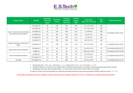
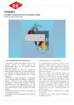
“COMPACT” QUADRI NORMALIZZATI DI MEDIA TENSIONE SERIE “COMPACT” EQUIPAGGIATI CON INTERRUTTORI DI MANOVRA-SEZIONATORI TIPO ROTATIVO SERIES “COMPACT” STANDARDIZED MEDIUM VOLTAGE SWITCHBOARDS PROVIDED WITH SWITCH-DISCONNECTORS ROTATING TYPE INDICE pag. INDEX pag. Caratteristiche generali 1 General characteristics 1 Tipologie standard 5 Standard types 5 - Scomparto risalita cavo “SRC” 7 - Cable riser “SRC” 7 - Scomparto arrivo e risalita sbarre “SRB” 8 - Incoming and bus riser unit “SRB” 8 - Scomparto arrivo e risalita sbarre “COMPACT SRBT” 9 - Incoming and bus riser unit “COMPACT SRBT” 9 - Scomparto arrivo/partenza con sezionatore “COMPACT SIV” 10 - Incoming/outgoing unit with disconnector “COMPACT SIV” 10 - Scomparto arrivo/partenza con interruttore di manovra sezionatore “COMPACT SIS” 11 - Incoming/outgoing unit with switch-disconnector “COMPACT SIS” 11 - Scomparto arrivo dal basso con sezionatore “COMPACT SIVC” 12 - Incoming from below unit with disconnector “COMPACT SIVC” 12 - Scomparto arrivo dal basso con interruttore di manovra sezionatore “COMPACT SISC” 13 - Incoming from below unit with switch-disconnector “COMPACT SISC” 13 - Scomparto protezione trasformatore “COMPACT STM” 14 - Transformer protection unit “COMPACT STM” 14 - Scomparto arrivo dal basso e protezione trasformatore “COMPACT STMC” 15 - Incoming from below and trasformer protection unit “COMPACT STMC” 15 - Scomparto misure “COMPACT SM” 16 - Measurement unit “COMPACT SM” 16 - Scomparto protezione generale con interruttore in SF6 “COMPACT SPG” 17 - General protection unit with SF6 circuit-breaker “COMPACT SPG” 17 - Scomparto alloggio trasformatore “AT” 18 - Transformer housing unit “AT” 18 Caratteristiche dei componenti Characteristics of components - Interruttore di manovra-sezionatore NIMSR/L 20 - Switch-disconnector type NIMSR/L 20 - Interruttore di manovra-sezionatore con fusibili NIMSR/TA 24 - Switch-disconnector type NIMSR/TA equipped with fuses 24 - Sezionatore rotativo SR 27 - Disconnector type SR 27 - Sezionatore di terra ST 30 - Earthing switch type ST 30 Tipologie di comandi 32 Operation mechanism types 32 Fondazioni e fissaggio a pavimento 35 Fixing to floor and foundation 35 L’ELETTROMECCANICA ADRIATICA S.p.A. si riserva il diritto di apportare, in qualsiasi momento, eventuali modifiche per motivi di carattere tecnico o commerciale; pertanto i dati e le illustrazioni contenute in questa pubblicazione sono aggiornate fino al momento dell’approvazione di stampa ELETTROMECCANICA ADRIATICA reserves the right to carry out, without any prior notice, any modifications it deems necessary in order to improve and meet any construction requirement. Therefore, the data and illustrations in this publication are updated up to the point of approval for printing. 22 \ 25 CARATTERISTICHE GENERALI GENERAL CHARACTERISTICS I quadri di media tensione COMPACT, isolati in aria, sono stati studiati per le cabine di distribuzione secondaria in M.T. e progettati per offrire all’utente una molteplicità di impiego e la possibilità di essere rispondenti alle più svariate esigenze di impianto. Il quadro è realizzabile assiemando i vari scomparti tipo completamente normalizzati. Nella progettazione degli scomparti si è tenuta in considerazione la funzionalità, la semplicità dei dispositivi di manovra e di blocco ed un lungo periodo di esercizio senza manutenzione. Lo scomparto tipo costituisce un complesso costituito da due celle sovrapposte e precisamente: cella superiore contenente il sistema di sbarre principale; cella inferiore contenente le apparecchiature elettriche di interruzione e sezionamento, di protezione, i trasformatori di corrente e di tensione ed i terminali. Le celle sono segregate tra di loro mediante un diaframma metallico che garantisce un grado di protezione IP2X in modo da consentire, con porta aperta e sbarre in tensione, l’accesso alla cella apparecchiature. The air-insulated M.V. “COMPACT” switchboards have been studied for M.V. secondary distribution compact stations and they have been designed to provide a wide variety of functions and service as required by modern power distribution system. The switchboard is realized with standardized typical units. During the design stage of the “COMPACT” units we took into consideration the functionality, the simplicity of operation and locking devices and a long period of service without any maintenance. Each typical unit is divided into two compartments placed one on the top of the other: an upper compartment containing the main bus-bars; a lower compartment containing various electrical equipment (circuit-breakers, isolators, protections, current transformers, voltage transformers and terminals). The compartments are segregated from each other with metal division which guarantee an IP2X protection degree, and when the door is open and the bus-bars are under tension, the acces to the equipment compartment is allowed. I quadri “COMPACT” presentano le seguenti caratteristiche: The technical aspects of “COMPACT” switchboards are summarized as follows: A) Massima sicurezza per il personale ottenuta con: Messa a terra di tutta la struttura del quadro e della segregazione metallica tra le celle; Visibilità delle posizioni degli interruttori di manovrasezionatori e dei sezionatori di messa a terra attraverso gli appositi oblò di ispezione; Interblocchi meccanici che garantiscono l’esatta sequenza delle manovre; Grado di protezione IP3X sull’involucro esterno.) A) Maximum safety for personnel thanks to: Earthing of both the whole switchboard structure and the metal division between the compartments; Possibility of inspecting the switch-disconnectors and the earthing switches through the special inspection windows; Mechanical interlocks which assure the exact operation sequence; IP3X protection degree on the external housing. B) Sicurezza contro gli incendi: La segregazione metallica tra le celle e l’utilizzo di materiali isolanti autoestinguenti impediscono il diffondersi di eventuali incendi. B) Protection against the spread of fire: The metal segregation of the compartments and the use of self-extinguishing insulating materials prevent the spreading of fire. C) Facile manovrabilità: Tutte le manovre di comando si effettuano dal fronte a mezzo di dispositivi semplici e funzionali, con segnalazioni meccaniche della posizione dei vari componenti. Chiare istruzioni per le manovre sono riportate sul fronte del quadro. C) Easy operation: All the various operations are carried out from the front of the switchboard by means of simple and functional devices, provided with mechanical signals indicating the position of the components. Clear operation instructions on the front of the switchboard. D) Versatilità Disponibilità di esecuzione per vari schemi di impianti. D) Versatility All current technical applications. E) Accurata scelta di materiali e quindi lunga durata di funzionamento: Il colore standard è grigio RAL 7030. Altri colori a richiesta. E) Long functional life throught careful choice of materials: Standard colour: grey RAL 7030 (other colours on request). CARATTERISTICHE E CAMPI DI IMPIEGO Il quadro COMPACT è costituito da unità modulari (Scomparti) con IMS tipo NIMSR. Possono essere impiegate terminazioni di cavo standard per uso interno. I campi di impiego dei quadri COMPACT sono fondamentalmente i seguenti: distribuzione secondaria pubblica distribuzione industriale FEATURES AND APPLICATION RANGES The COMPACT swicthboard is made of a modular units (Switchboards) with NIMSR. It’s possible to use standard cable glands (indoor use). The most important application ranges of the COMPACT switchboards are the following: public secondary distribution industrial distribution CARATTERISTICHE DELL’IMS L’interruttore di manovra-sezionatore NIMSR è completamente isolato in aria. L’involucro metallico esterno funge da segregazione tra vano terminali e sbarre con elevato grado di sicurezza. Il comando è particolarmente affidabile e può essere sia manuale che motorizzato. SWITCH-DISCONNECTOR FEATURES The NIMSR Switch-disconnector is completely air insulated. The metallic body makes the segregation between terminal cable box and busbar with high safe degree. The operating mechanism is very reliable and it is possible to have hand or motorized system. GRANDEZZE NOMINALI / RATED VALUES Tensi one nomi nal e Rated voltage Frequenza nomi nal e Rated nominal frequancy Tensi one di prova 1 mi n. 50 Hz vers o terra e fra l e fasi Test voltage 1 min. 50 Hz against earth and between the phases Tensi one di prova 1 mi n. 50 Hz tra i contatti aperti del l’ IMS Test voltage 1 min. 50 Hz between the open contacts of the switch-disconnector Tensi one di manovra ad impuls o verso terra e fra le fasi Impulse wit hst and volt age against earth and between t he phases Tensi one di manovra ad impuls o tra i contatti aperti del l ’IMS Impulse withstand voltage between the open contacts of the switch-disconnector Corrente nominal e Rated current Corrente nominal e sbarre Bus-bar rated current Corrente ammis si bi le nominal e di breve durata (1 sec.) Rated short-time withstand current (1 sec.) Val ore di cresta del l a corrente ammis si bil e nominal e Rated peak withstand current [kV] 12 17,5 24 [Hz] 50/60 50/60 50/60 [kV] 28 38 50 [kV] 32 45 60 [kV] 75 95 125 [A] 85 110 145 [A] 400 400 400 [A] 400/630 400/630 400/630 [kA] 12,5/16 12,5/16 12,5/16 [kA] 31,5-40 31,5-40 31,5-40 SERIE COMPACT COMPACT SERIES RIFERIMENTI A NORMATIVE STANDARDS RAPPORTI DI PROVA Gli scomparti della serie COMPACT hanno positivamente superato in laboratori ufficiali tutte le prove di tipo in accordo alle Norme internazionali (IEC, CEI) richieste dalle stesse. TEST REPORTS COMPACT cubicles have successfully passed all the type tests requested by the international and national Standards (IEC, CEI) in officially acknowledged testing laboratories. Norme Internazionali IEC 60265, 62271-200, 62271-102, 60694 Norme Internazionali IEC 60265, 62271-200, 62271-102, 60694 Altre Norme Norme Italiane CEI EN 62271-200 Omologazione ENEL DY401-402-403-404 406-408 Antinfortunistiche Italiane (D.P.R. 547) Other Standards Italian CEI EN 62271-200 Standards ENEL Homologation to Spec. DY 401-402 403-404-406-408 Italian accident prevention law (D.P.R. 547) SISTEMA QUALITA’ Il ns. sistema progettuale e produttivo viene effettuato sotto la rigida applicazione di un Sistema Qualità aziendale certificato dal CSQ (EQNET Member) secondo la normativa ISO 9001-2000 QUALITY SYSTEM Our designing and manufacturing system is made under the rigid application of company Quality System, certified by CSQ (EQNET Member), in compliance with ISO 9001-2000 Standards. AMBIENTE Il Sistema Qualità è integrato con una politica ambientale che riveste un ruolo fondamentale all’interno dell’Elettromeccanica Adriatica. Il sistema di Gestione Ambientale è certificato dal CSQ (EQNET member) secondo la normativa ISO 14001-2004. ENVIROMENT The Quality System is integrated with an Enviromental policy that is of primary importance for our company. Enviromental Management Systems is certified by CSQ ( EQNET member) in compliance with ISO 14001-2004 standard. Per tener conto della evoluzione sia delle norme sia dei materiali, le caratteristiche e le dimensioni di ingombro indicate nel presente catalogo si potranno ritenere impegnative solo dopo conferma da parte nostra. Due to the continuous development of Standards as well as of materials, the characteristics and dimensions indicated in this catalogue must be regarded as binding only on our confirmation. TIPOLOGIE STANDARD STANDARD TYPES SCOMPARTO RISALITA CAVO “SRC” SCOMPARTO ARRIVO E RISALITA SBARRE“SRB” SCOMPARTO ARRIVO E RISALITA SBARRE“COMPACT SRBT” SCOMPARTO ARRIVO/PARTENZA CON SEZIONATORE “COMPACT SIV” CABLE RISER UNIT “RSC” INCOMING AND BUS RISER UNIT “SRB” INCOMING AND BUS-BAR RISER UNIT “COMPACT SRBT” INCOMING/OUTGOING UNIT WITH SWITCH-DISCONNECTOR “COMPACT SIV” SCOMPARTO ARRIVO/PARTENZA CON INTERRUTTORE DI MANOVRA-SEZIONATORE “COMPACT SIS” SCOMPARTO ARRIVO DAL BASSO CON SEZIONATORE “COMPACT SIVC” SCOMPARTO ARRIVO DAL BASSO CON INTERRUTTORE DI MANOVRA-SEZIONATORE “COMPACT SISC” SCOMPARTO PROTEZIONE TRASFORMATORE “COMPACT STM” INCOMING/OUTGOING UNIT WITH SWITCH-DISCONNECTOR “COMPACT SIS” INCOMING FROM BELOW UNIT WITH DISCONNECTOR “COMPACT SIVC” INCOMING FROM BELOW UNIT WITH SWITCH-DISCONNECTOR “COMPACT SISC” TRANSFORMER PROTECTION UNIT “COMPACT STM” SCOMPARTO ARRIVO DAL BASSO E PROTEZIONE TRASFORMATORE “COMPACT STMC” INCOMING FROM BELOW AND TRANSFORMER PROTECTION UNIT “COMPACT STMC” SCOMPARTO MISURE “COMPACT SM” MEASUREMENT UNIT “COMPACT SM” SCOMPARTO PROTEZIONE GENERALE CON INTERRUTTORE IN SF6 “COMPACT SPG” GENERAL PROTECTION UNIT WITH SF6 CIRCUIT-BREAKER “COMPACT SPG” SCOMPARTO ALLOGGIO TRASFORMATORE “SAT” HOUSING TRANSFORMER UNIT “SAT” SRC SCOMPARTO RISALITA CAVO CABLE RISER UNIT COMPOSIZIONE BASE SCOMPARTI BASE UNIT COMPONENTS Dimensioni (L=350mm, H=1950mm, P=1150mm) Dimensions (W=350 mm, H=1950mm, D=1150mm) Peso (101 Kg) Weight (101 Kg) Supporto cavi Sbarra di terra Targa di identificazione scomparto Targa pericolo di folgorazione Cable supports Earthing bar Reference plate Electrocutioning plate EQUIPAGGIAMENTI A RICHIESTA OPTIONAL COMPONENTS Zoccolo di rialzo da 300 mm Rise 300 mm SRB SCOMPARTO ARRIVO E RISALITA SBARRE INCOMING AND BUS RISER UNIT COMPOSIZIONE BASE SCOMPARTI BASE UNIT COMPONENTS Dimensioni (L=550 mm, H=1950mm, P=1150mm) Dimensions (W=550 mm, H=1950mm, D=1150mm) Peso (101 Kg) Weight (101 Kg) Sbarre principali Sbarra di terra Supporto terminali di cavo Targa di identificazione scomparto Targa pericolo di folgorazione Main busbars Earthing bar Cable gland support Reference plate Electrocutioning plate EQUIPAGGIAMENTI A RICHIESTA OPTIONAL COMPONENTS Zoccolo di rialzo da 300 mm Isolatori capacitivi con lampade Rise 300 mm Capacitor dividers and lamps SRBT SCOMPARTO ARRIVO E RISALITA SBARRE “COMPACT SRBT” INCOMING AND BUS-BAR RISER UNIT “COMPACT SRBT” COMPOSIZIONE BASE SCOMPARTI BASE UNIT COMPONENTS Dimensioni (L=550 mm, H=1950mm, P=1150mm) Dimensions (W=550 mm, H=1950mm, D=1150mm) Peso (115 Kg) Weight (115 Kg) Sbarre principali Sbarra di terra Oblò di ispezione Interblocco meccanico con la portella Sezionatore di terra Supporto terminali di cavo Targa di identificazione scomparto Schema sinottico Targa sequenza manovre Main busbars Earthing bar Inspection windows Safety interlock with the door Earthing switch Cable gland support Reference plate Synoptic diagram Reference plate for operation steps EQUIPAGGIAMENTI A RICHIESTA OPTIONAL COMPONENTS Blocco a chiave ST (precisare estraibilità) Isolatori capacitivi con lampade Contatti ausiliari Resistenza anticondensa Zoccolo di rialzo 300 mm. Key interlock ST (extraction to be defined) Capacitor dividers and lamps Auxiliary contacts Space heater Rise 300 mm SIV SCOMPARTO ARRIVO/PARTENZA CON SEZIONATORE “COMPACT SIV” INCOMING/OUTGOING UNIT WITH DISCONNECTOR “COMPACT SIV” COMPOSIZIONE BASE SCOMPARTI BASE UNIT COMPONENTS Dimensioni (L=700 mm, H=1950mm, P=1150mm) Dimensions (W=700 mm, H=1950mm, D=1150mm) Peso (260 Kg) Weight (260 Kg) Sbarre principali Sbarra di terra Oblò di ispezione Interblocchi meccanici Sezionatore a vuoto Sezionatore di terra Supporto terminali di cavo Targa di identificazione scomparto Schema sinottico Targa sequenza manovre Main busbars Earthing bar Inspection windows Safety interlocks Disconnector Earthing switch Cable gland support Reference plate Synoptic diagram Reference plate for operation steps EQUIPAGGIAMENTI A RICHIESTA OPTIONAL COMPONENTS Blocchi a chiave SR e/o ST (precisare estraibilità) Isolatori capacitivi con lampade Contatti ausiliari su SR e/o ST Resistenza anticondensa Illuminazione interna Zoccolo di rialzo 300 mm. Vano morsettiera ausiliari Cassetta porta strumenti Key interlocks SR e/o ST (extraction to be defined) Capacitor dividers and lamps Auxiliary contacts on SR and/or ST Space heater Internal lighting for unit Rise 300 mm Terminal board compartment Instrument box SIS ARRIVO/PARTENZA CON INT. DI MANOVRA-SEZIONATORE “COMPACT SIS” INCOMING/OUTGOING UNIT WITH SWITCH-DISCONNECTOR “COMPACT SIS” COMPOSIZIONE BASE SCOMPARTI BASE UNIT COMPONENTS Dimensioni (L=700 mm, H=1950mm, P=1150mm) Dimensions (W=700 mm, H=1950mm, D=1150mm) Peso (260 Kg) Weight (260 Kg) Sbarre principali Sbarra di terra Oblò di ispezione Interblocchi meccanici Interruttore di manovra-sezionatore Sezionatore di terra Supporto terminali di cavo Targa di identificazione scomparto Schema sinottico Targa sequenza manovre Main busbars Earthing bar Inspection windows Safety interlocks Switch Disconnector Earthing switch Cable gland support Reference plate Synoptic diagram Reference plate for operation steps EQUIPAGGIAMENTI A RICHIESTA OPTIONAL COMPONENTS Blocchi a chiave IMS e/o ST (precisare estraibilità) Isolatori capacitivi con lampade Contatti ausiliari su IMS e/o ST Resistenza anticondensa Illuminazione interna Zoccolo di rialzo 300 mm. Vano morsettiera ausiliari Cassetta porta strumenti Comando motor. a sup. di punto morto (24 Vcc) (Altre tensioni a richiesta) Key interlocks IMS e/o ST (extraction to be defined) Capacitor dividers and lamps Auxiliary contacts on IMS and/or ST Space heater Internal lighting for unit Rise 300 mm Terminal board compartment Instrument box Motor op. mech. on exceending dead center (24 Vcc) (Other voltage values on request) SIVC SCOMPARTO ARRIVO DAL BASSO CON SEZIONATORE “COMPACT SIVC” INCOMING FROM BELOW UNIT WITH DISCONNECTOR “COMPACT SIVC” COMPOSIZIONE BASE SCOMPARTI BASE UNIT COMPONENTS Dimensioni (L=700 mm, H=1950mm, P=1150mm) Dimensions (W=700 mm, H=1950mm, D=1150mm) Peso (270 Kg) Weight (270 Kg) Sbarre principali Sbarra di terra Oblò di ispezione Interblocchi meccanici Sezionatore a vuoto Sezionatore di terra Supporto terminali di cavo Targa di identificazione scomparto Schema sinottico Targa sequenza manovre Main busbars Earthing bar Inspection windows Safety interlocks Disconnector Earthing switch Cable gland support Reference plate Synoptic diagram Reference plate for operation steps EQUIPAGGIAMENTI A RICHIESTA OPTIONAL COMPONENTS Blocchi a chiave SR e/o ST (precisare estraibilità) Isolatori capacitivi con lampade Contatti ausiliari su SR e/o ST Resistenza anticondensa Illuminazione interna Zoccolo di rialzo 300 mm. Vano morsettiera ausiliari Trasformatori di tensione Trasformatori di corrente Key interlocks SR e/o ST (extraction to be defined) Capacitor dividers and lamps Auxiliary contacts on SR and/or ST Space heater Internal lighting for unit Rise 300 mm Terminal board compartment Voltage transformers Current transformers SISC SCOMPARTO ARRIVO DAL BASSO CON INTERRUTTORE DI MANOVRA-SEZIONATORE “COMPACT SISC” INCOMING FROM BELOW UNIT WITH SWITCH-DISCONNECTOR “COMPACT SISC” COMPOSIZIONE BASE SCOMPARTI BASE UNIT COMPONENTS Dimensioni (L=700 mm, H=1950mm, P=1150mm) Dimensions (W=700 mm, H=1950mm, D=1150mm) Peso (270 Kg) Weight (270 Kg) Sbarre principali Sbarra di terra Oblò di ispezione Interblocchi meccanici Interruttore di manovra-sezionatore Sezionatore di terra Supporto terminali di cavo Targa di identificazione scomparto Schema sinottico Targa sequenza manovre Main busbars Earthing bar Inspection windows Safety interlocks Switch Disconnector Earthing switch Cable gland support Reference plate Synoptic diagram Reference plate for operation steps EQUIPAGGIAMENTI A RICHIESTA OPTIONAL COMPONENTS Blocchi a chiave IMS e/o ST (precisare estraibilità) Isolatori capacitivi con lampade Contatti ausiliari su IMS e/o ST Resistenza anticondensa Illuminazione interna Zoccolo di rialzo 300 mm. Vano morsettiera ausiliari Trasformatori di tensione Trasformatori di corrente Comando motor. a sup. di punto morto (24 Vcc) (Altre tensioni a richiesta) Key interlocks IMS e/o ST (extraction to be defined) Capacitor dividers and lamps Auxiliary contacts on IMS and/or ST Space heater Internal lighting for unit Rise 300 mm Terminal board compartment Voltage transformers Current transformers Motor op. mech. on exceending dead center (24 Vcc) (Other voltage values on request) STM SCOMPARTO PROTEZIONE TRASFORMATORE “COMPACT STM” TRANSFORMER PROTECTION UNIT “COMPACT STM” COMPOSIZIONE BASE SCOMPARTI BASE UNIT COMPONENTS Dimensioni (L=700 mm, H=1950mm, P=1150mm) Dimensions (W=700 mm, H=1950mm, D=1150mm) Peso (310 Kg) Weight (310 Kg) Sbarre principali Sbarra di terra Oblò di ispezione Interblocchi meccanici Interruttore di manovra-sezionatore Sezionatore di terra Supporto terminali di cavo Targa di identificazione scomparto Schema sinottico Targa sequenza manovre Main busbars Earthing bar Inspection windows Safety interlocks Switch Disconnector Earthing switch Cable gland support Reference plate Synoptic diagram Reference plate for operation steps EQUIPAGGIAMENTI A RICHIESTA OPTIONAL COMPONENTS Blocchi a chiave IMS e/o ST (precisare estraibilità) Isolatori capacitivi con lampade Contatti ausiliari su IMS e/o ST Resistenza anticondensa Illuminazione interna Zoccolo di rialzo 300 mm. Vano morsettiera ausiliari Cassetta porta strumenti Fusibili MT Bobina di apertura (220 Vca/110 Vcc) Key interlocks IMS e/o ST (extraction to be defined) Capacitor dividers and lamps Auxiliary contacts on IMS and/or ST Space heater Internal lighting for unit Rise 300 mm Terminal board compartment Instrument box MV fuses Opening coil (220 Vac/110 Vdc) STMC SCOMPARTO ARRIVO DAL BASSO E PROTEZIONE TRASFORMATORE “COMPACT STMC” INCOMING FROM BELOW AND TRANSFORMER PROTECTION UNIT “COMPACT STMC” COMPOSIZIONE BASE SCOMPARTI BASE UNIT COMPONENTS Dimensioni (L=700 mm, H=1950mm, P=1150mm) Dimensions (W=700 mm, H=1950mm, D=1150mm) Peso (310 Kg) Weight (310 Kg) Sbarre principali Sbarra di terra Oblò di ispezione Interblocchi meccanici Interruttore di manovra-sezionatore Sezionatore di terra Targa di identificazione scomparto Schema sinottico Targa sequenza manovre Main busbars Earthing bar Inspection windows Safety interlocks Switch Disconnector Earthing switch Reference plate Synoptic diagram Reference plate for operation steps EQUIPAGGIAMENTI A RICHIESTA OPTIONAL COMPONENTS Blocchi a chiave IMS e/o ST (precisare estraibilità) Isolatori capacitivi con lampade Contatti ausiliari su IMS e/o ST Resistenza anticondensa Illuminazione interna Zoccolo di rialzo 300 mm. Vano morsettiera ausiliari Fusibili MT Bobina di apertura (220 Vca/110 Vcc) Key interlocks IMS e/o ST (extraction to be defined) Capacitor dividers and lamps Auxiliary contacts on IMS and/or ST Space heater Internal lighting for unit Rise 300 mm Terminal board compartment MV fuses Opening coil (220 Vac/110 Vdc) SM SCOMPARTO MISURE “COMPACT SM” MEASUREMENT UNIT “COMPACT SM” COMPOSIZIONE BASE SCOMPARTI BASE UNIT COMPONENTS Dimensioni (L=700 mm, H=1950mm, P=1150mm) Dimensions (W=750 mm, H=1950mm, D=1150mm) Peso (310 Kg escluso TA e TV) Weight (310 Kg - CT’s and VT’s not included) Sbarre principali Sbarra di terra Oblò di ispezione Interblocchi meccanici Sezionatore a vuoto Sezionatore di terra Supporto terminali di cavo Targa di identificazione scomparto Schema sinottico Targa sequenza manovre Main busbars Earthing bar Inspection windows Safety interlocks Disconnector Earthing switch Cable gland support Reference plate Synoptic diagram Reference plate for operation steps EQUIPAGGIAMENTI A RICHIESTA OPTIONAL COMPONENTS Blocchi a chiave SR e/o ST (precisare estraibilità) Isolatori capacitivi con lampade Contatti ausiliari su SR e/o ST Resistenza anticondensa Illuminazione interna Zoccolo di rialzo 300 mm Vano morsettiere ausiliari Cassetta porta strumenti Trasformatori di tensione Trasformatori di corrente Fusibili MT Key interlocks SR e/o ST (extraction to be defined) Capacitor dividers and lamps Auxiliary contacts on SR and/or ST Space heater Internal lighting for unit Rise 300 mm Terminal board compartment Instrument box Voltage transformers Current transformers MV fuses SPG SCOMPARTO PROTEZIONE GENERALE CON INTERRUTTORE IN SF6 “COMPACT SPG” GENERAL PROTECTION UNIT WITH SF6 CIRCUIT-BREAKER “COMPACT SPG” COMPOSIZIONE BASE SCOMPARTI BASE UNIT COMPONENTS Dimensioni (L=900 mm, H=1950mm, P=1150mm) Dimensions (W=900 mm, H=1950mm, D=1150mm) Peso (370 Kg – Int., TA, TV e box BT non incluso) Weight (370 Kg – CB, CT’s, VT’s and LV box not included)) Sbarre principali Sbarra di terra Oblò di ispezione Interblocchi meccanici Sezionatore con blocco a chiave Sezionatore di terra Supporto terminali di cavo Targa di identificazione scomparto Schema sinottico Targa sequenza manovre Main busbars Earthing bar Inspection windows Safety interlocks Disconnector with key interlock Earthing switch Cable gland support Reference plate Synoptic diagram Reference plate for operation steps EQUIPAGGIAMENTI A RICHIESTA OPTIONAL COMPONENTS Blocchi a chiave SR e/o ST (precisare estraibilità) Isolatori capacitivi con lampade Contatti ausiliari su SR e/o ST Resistenza anticondensa Illuminazione interna Zoccolo di rialzo 300 mm. Vano morsettiere ausiliari Cassetta porta strumenti Trasformatori di corrente/tensione Interruttore fisso in SF6 ed accessori Interruttore estraibile in SF6 ed accessori Key interlocks SR e/o ST (extraction to be defined) Capacitor dividers and lamps Auxiliary contacts on SR and/or ST Space heater Internal lighting for unit Rise 300 mm. Terminal board compartment Instrument box Current/voltage transformers Fixed SF6 circuit breaker and accessories Withdrawable SF6 circuit breaker and accessories SAT SCOMPARTO ALLOGGIO TRASFORMATORE “AT” TRANSFORMER HOUSING UNIT “AT” COMPOSIZIONE BASE SCOMPARTI BASE UNIT COMPONENTS Sbarra di terra Oblò di ispezione Blocco a chiave Vano morsettiere ausiliari Dispositivo di illuminazione interna Targa di identificazione scomparto Schema sinottico Targa sequenza manovre Earthing bar Inspection windows Key interlock Terminal board compartment Internal lighting fon unit Reference plate Synoptic diagram Reference plate for operation steps DIMENSIONI DIMENSIONS Si gla Code AT/250 AT/400 AT/630 AT/800 AT/1000 Larghez za Width 1600 1800 2000 2200 2400 Al tezz a Height 1950 1950 1950 2250 2250 Profondità Depth 1150 1300 1300 1600 1600 Potenza trasformatore Transformer rating 250 400 630 800 1000 TABELLA PER LA SCELTA DEI FUSIBILI DI PROTEZIONE DEI TRASFORMATORI FUSES TABLE TO PROTECT TRANSFORMER Tens. Nom . rete (kV) Service voltage (kV) 3 5 6 10 12 15 17,5 20 24 30 36 50 25 16 16 10 6 6 6 6 6 6 6 Pote nza nom inale del trasform atore (kVA) / Transformer rating (kVA) 75 100 125 160 200 250 315 400 500 630 800 1000 1250 1600 2000 2500 Corrente te rmica nom inale I del fusibil e (A) / Rated thermal current I of the fuse (A) 40 40 63 63 100 100 100 100 100 160 25 25 40 40 63 63 100 100 100 100 100 160 25 25 40 40 40 63 63 100 100 100 100 100 160 16 16 25 25 25 40 40 63 63 63 100 100 100 100 160 16 16 16 25 25 40 40 40 63 63 100 100 100 100 160 160 10 16 16 25 25 25 40 40 40 63 63 100 100 100 100 6 10 16 16 25 25 25 40 40 63 63 63 100 100 100 100 6 10 16 16 16 25 25 40 40 40 63 63 63 100 100 100 6 6 10 16 16 16 25 25 40 40 40 63 63 100 100 100 6 6 6 10 16 16 16 25 25 40 40 40 6 6 6 10 10 16 16 25 25 25 40 40 NIMSR/L INTERRUTTORE DI MANOVRA-SEZIONATORE SWITCH-DISCONNECTOR CARATTERISTICHE DEI COMPONENTI CHARACTERISTICS OF COMPONENTS L’interruttore di manovra-sezionatore realizza la sua funzione mediante tre isolatori passanti che opportunamente fissati ad un supporto, ruotano all’interno di un telaio. Nella parte inferiore del telaio, sono installati tre isolatori portanti cilindrici con i contatti rompiarco fissi ed il dispositivo di soffio, mentre nella parte superiore, sono installati tre isolatori portanti con i contatti striscianti. L’interruttore di manovra-sezionatore è equipaggiato con un comando idoneo ad effettuare le manovra di chiusura e apertura ad una velocità indipendente dall’operatore e, nella posizione di aperto, realizza la segregazione tra la cella apparecchiature e la cella sbarre. La manovra avviene dal fronte del quadro e può essere dotata di blocco a chiave, lucchetto e di contatti ausiliari. L’interruttore di manovra-sezionatore è accoppiato con un sezionatore di terra ST. E’ disponibile il comando motorizzato a superamento di punto morto. The switch-disconnector operates by means of three through-bar bushing insulators. They are fixed to a support and rotate inside a frame. Three cylindrical post insulators, provided with fixed arc-breaking contacts and with air blowing device, are housed in the lower part of the frame. Three post insulator, with slethering contacts, are situated in the upper part of the frame.The switchdisconnector is fitted with an operating mechanism which carries out the closing and opening operations with a velocity independent from the operator. In the open position, the switch-disconnector guarantees the segregation between the equipment compartment and the bus-bar compartment. The operation is always carried out from the front of the switchboard and can be fitted with a key lock, a padlocking facility and auxiliary contacts. The switch-disconnector is coupled with an earthing switch type ST. It’s possible to have a motor operator mechanism on exceending dead center NIMSR/L CARATTERISTICHE TECNICHE TECHNICAL FEATURES GRANDEZZE NO MINALI / RATED VALUES Te nsion e nominale Rated nominal voltage Fre que nza nominale Rated nominal frequancy Te nsion e di prova 1 mi n. 50 Hz ve rso terra e fra le fasi Test voltage 1 min. 50 Hz against earth and between the phases Te nsion e di prova 1 mi n. 50 Hz tra i contatti aperti del l’ IMS Test voltage 1 min. 50 Hz between the switch-disconnector opened contacts Te nsion e di manovra ad impul so verso terra e fra le fasi Impulse withstand voltage against earth and between the phases Te nsion e di manovra ad impul so tra i contatti ape rti de ll ’IMS Impulse withstand voltage between the switch-disconnector opened contacts Corre nte nominale Rated nominal current Potere di inte rruzi one nominal e cari co pre vale nte me nte attivo Rated breaking capacity mainly active load Potere di inte rruzi one nominal e trasformatori a vuoto Rated breaking capacity no-load transformer Potere di inte rruzi one nominal e li nee a vuoto Rated breaking capacity no-load overhead lines Potere di inte rruzi one nominal e cavi a vu oto Rated breaking capacity no-load cables Corre nte ammi ssibi le nomi nal e di breve durata (1 se c.) Rated short-time withstand current (1 sec.) Valore di cre sta dell a corren te ammissi bil e nomi nale Rated peak withstand current Potere di stabil imento Making capacity Cicl o di omologazi one se condo le norme IEC IEC standard test cycle Nume ro di manovre meccaniche Endurance operation test (cycles) [kV] 12 17,5 24 [Hz] 50/60 50/60 50/60 [kV] 28 38 50 [kV] 32 45 60 [kV] 75 95 125 [kV] 85 110 145 [A] 400/630 400/630 400/630 [A] 400 400 400 [A] 6,3 6,3 6,3 [A] 10 10 10 [A] 16 16 16 [kA] 12,5-16 12,5-16 12,5-16 [kA] 31,5-40 31,5-40 31,5-40 [kA] 31,5-40 31,5-40 31,5-40 E1 E1 E1 1000 1000 1000 NIMSR/L DIMENSIONI D’INGOMBRO E INSTALLAZIONE OVERALL AND INSTALLATION DIMENSIONS N.B.:Schema rappresentato ad IMS aperto, terre aperte e assenza di alimentazione ausiliaria /diagram with LBS/earthing switch in opened position and not auxiliary supply Connessioni motore / motor connections Connessioni su scheda / card connections Connessioni a connettore 14 poli / connections to 14 poles connector NIMSR/L SCHEMA ELETTRICO 24Vcc - 48Vcc WIRING DIAGRAM 24Vdc – 48 Vdc NIMSR/TA INTERRUTTORE DI MANOVRA-SEZIONATORE CON FUSIBILI SWITCH-DISCONNECTOR EQUIPPED WITH FUSES CARATTERISTICHE DEI COMPONENTI CHARACTERISTICS OF COMPONENTS L’interruttore di manovra-sezionatore è strutturalmente simile all’interruttore di manovra-sezionatore SRS/L ma è equipaggiato con un comando con le seguenti caratteristiche: Durante la manovra di chiusura, effettuata con una leva di comando, vengono caricate, contemporaneamente le molle di chiusura e apertura. La chiusura viene effettuata al termine dell’operazione di caricamento, mentre l’apertura, può effettuarsi a mezzo di leva di comando, sistema di sgancio attivato dal percussore dei fusibili, sganciatore di apertura. Le manovre di chiusura e apertura avvengono ad una velocità indipendente dall’operatore. La manovra può essere dotata di blocco a chiave, lucchetto e di contatti ausiliari. L’interruttore di manovra-sezionatore è accoppiato con un sezionatore di terra ST e di portafusibili che consentono l’installazione di fusibili 24-17,5-12 kV. Structurally, the switch-disconnector is similar to the “SRS/L” switch-disconnector, but it’s equipped with an operating mechanism which has the following characteristics: During the closing, carried out by means of an operating lever, the closing and opening springs are charged. The closing operation is carried out at the end of the charging operation. The opening can be executed by means of an operating lever, release system activated by the fuse striker and a shunt-trip release. The velocity of the closing and opening operations is independant from the operator. Operation can be fitted with a key lock, a padlock facility and auxiliary contacts. The switch-disconnector is coupled with an earting switch type “ST” and with fuse-holders, equipped with kV 24-17,5-12 fuses. NIMSR/TA CARATTERISTICHE TECNICHE TECHNICAL FEATURES GRANDEZZE NO MINALI / RATED VALUES Te nsione n om inal e Rated nom inal voltage Fre que nz a nomi nale Rated nom inal frequancy Te nsione di prova 1 m in. 50 Hz ve rso te rra e fra le fasi Test voltage 1 m in. 50 Hz against earth and between the phases Te nsione di prova 1 m in. 50 Hz tra i contatti ape rti de ll ’ IMS Test voltage 1 m in. 50 Hz between the open contacts of the switch-disconnector Te nsione di m anovra ad im pu lso ve rso te rra e fra le fasi Im pulse withstand voltage against earth and between the phases Te nsione di m anovra ad im pu lso tra i con tatti ape rti de ll’IMS Im pulse withstand voltage between the open contacts of the switch-disconnector C orre nte nomin ale Rated nom inal current Pote re di i nte rru z ione nomi nale cari co pre val e nte me n te atti vo Rated breaking capacity m ainly active load Pote re di i nte rru z ione nomi nale trasformatori a vu oto Rated breaking capacity no-load transform er Pote re di i nte rru z ione nomi nale l ine e a vuoto Rated breaking capacity no-load overhead lines Pote re di i nte rru z ione nomi nale cavi a vu oto Rated breaking capacity no-load cables C orre nte ammissibile n ominal e di bre ve durata 1 se c. Rated short-tim e withstand current 1 sec. Pote re di stabil ime nto ( IMS e Se z . di te rra a m onte fu s.) Making capacity (switch-disconnector and upstream earthing switch) C orre nte ammissibile n ominal e di bre ve durata 1 se c. ( Se z . di te rra a val le fu s.) Rated short-tim e withstand current 1 sec. (downstream earthing switch) C iclo di om ol ogaz ione se condo l e norm e IEC IEC standard test cycle Nume ro di manovre m e ccaniche Endurance operation test (cycles) [kV] 12 17,5 24 [Hz] 50/60 50/60 50/60 [kV] 28 38 50 [kV] 32 45 60 [kV] 75 95 125 [kV] 85 110 145 [A] 400 400 400 [A] 400 400 400 [A] 6,3 6,3 6,3 [A] 10 10 10 [A] 16 16 16 [kA] 12,5-16 12,5-16 12,5-16 [kA] 31,5-40 31,5-40 31,5-40 [kA] 3,15 3,15 3,15 E1 E1 E1 1000 1000 1000 NIMSR/TA DIMENSIONI D’INGOMBRO E INSTALLAZIONE OVERALL AND INSTALLATION DIMENSIONS SR SEZIONATORE DISCONNECTOR CARATTERISTICHE DEI COMPONENTI CHARACTERISTICS OF COMPONENTS Il sezionatore SR è strutturalmente simile all’interruttore di manovra-sezionatore SRS/L ma presenta le seguenti variazioni: contatto fisso superiore ridotto; eliminazione contatti rompiarco fisso e mobile; eliminazione dispositivo di soffio aria. Il sezionatore è equipaggiato con un comando a manovra manuale dipendente sia in chiusura che in apertura. La manovra può essere dotata di blocco a chiave, lucchetto e di contatti ausiliari. Il sezionatore può essere accoppiato con un sezionatore di terra ST. Structurally, the disconnector type “SR” is similar to the “SRS/L” switch-disconnector with the following changes: reduced upper fixed contact; elimination of both the moving and fixed arc-breaking contacts; elimination of the air blowing device. The disconnector is equipped, both for closing and opening operations, with a manual operating mechanism. Operation can be fitted with a keylock, padlock facility and auxiliary contacts. The disconnector can be coupled with an earthing switch type “ST”. SR SEZIONATORE DISCONNECTOR GRANDEZZE NO MINALI / RATED VALUES Tensione nominal e Rated nom inal voltage Frequenza nom inale Rated nom inal frequancy Tensione di prova 1 min. 50 Hz verso terra e fra le fasi Test voltage 1 m in. 50 Hz against earth and between the phases Tensione di prova 1 min. 50 Hz tra i contatti ape rti dell’ IMS Test voltage 1 m in. 50 Hz between the open contacts of the switch-disconnector Tensione di manovra ad im pulso verso terra e fra le fasi Im pulse withstand voltage against earth and between the phases Tensione di manovra ad im pulso tra i contatti aperti dell ’IMS Im pulse withstand voltage between the open contacts of the switch-disconnector C orrente nom inale Rated nom inal current C orrente nom inale sbarre Bus-bar rated current C orrente ammi ssibi le nominal e di bre ve durata (1 sec.) Rated short-tim e withstand current (1 sec.) Valore di cresta dell a corrente am missibile nom inale Rated peak withstand current Numero di m anovre m eccaniche Endurance operation test (cycles) [kV] 12 17,5 24 [Hz] 50/60 50/60 50/60 [kV] 28 38 50 [kV] 32 45 60 [kV] 75 95 125 [kV] 85 110 145 [A] 400/630 400/630 400/630 [A] 400/630 400/630 400/630 [kA] 12,5-16 12,5-16 12,5-16 [kA] 31,5-40 31,5-40 31,5-40 1000 1000 1000 SR DIMENSIONI D’INGOMBRO E INSTALLAZIONE OVERALL AND INSTALLATION DIMENSIONS ST SEZIONATORE DI TERRA EARTHING SWITCH CARATTERISTICHE DEI COMPONENTI CHARACTERISTICS OF COMPONENTS La manovra del sezionatore di terra avviene con un comando dipendente sia in chiusura che in apertura. Il sezionatore può essere accoppiato con gli interruttori di manovra-sezionatori e con i sezionatori. Il sezionatore di terra è completo di interblocco meccanico reciproco tra porta e sezionatore di terra (accesso alla cella solo con sezionatore in posizione di chiuso ed impedimento della manovra del sezionatore a porta aperta). Il blocco può essere rimosso con apposito utensile garantendo il grado di protezione IP2X. L’interblocco, una volta rimosso, ritorna nella sua posizione iniziale quando l’utensile viene tolto. Qualora venga rimosso il blocco non è possibile chiudere la porta se non dopo aver chiuso il sezionatore di messa a terra. La manovra può essere dotata di blocco a chiave, lucchetto e di contatti ausiliari. Il sezionatore di terra è previsto per una corrente di breve durata di 12,5-16 kA/1”. E’ prevista anche la versione di ST con potere di chiusura pari a 40 kA di cresta. Operation of the earthing switch takes place with a manual operating mechanism, both for closing and opening.The earthing switch can be coupled with other components, such as switch-disconnectors and isolators. The earthing switches are fitted with interlocks. In particular: mutual mechanical interlock between the door and the earthing switch which allows the door of the compartment to be opened only if the earthing switch is closed. It does not allow the earthing switch operation when the door is open. The lock can be deactivated by means of a special tool, which guarantees the IP2X protection degree. When the tool is removed , the lock returns on its starting position. When the lock is deactivated, the door can be closed only if the earthing switch is closed. Operation can be fitted with a key lock, padlock facility and auxiliary contacts. The earthing switches are planned for a short-time current of 1 sec. Equal to 12,5 or 16 kA. ST CARATTERISTICHE TECNICHE TECHNICAL FEATURES GRANDEZZE NO MINALI / RATED VALUES Tension e nomin ale Rated voltage C orren te ammi ssibile nominale di breve durata (1 sec.) Rated short -time withstand current (1 sec.) Valore di cre sta de lla corre nte ammissi bil e n omin ale Rated peak withstand current [kV] 24 [kA] 12,5-16 [kA] 31,5-40 TIPOLOGIE DI COMANDI OPERATING MECHANISM TYPES COMANDO TIPO R Operating mechanism type R Le operazioni di apertura e chiusura avvengono a velocità indipendente dall’operatore. Durante l’operazione di apertura e chiusura si carica una molla che determina la manovra rapida. Possibilità di contatti ausiliari e blocchi a chiave. The speed of the closing and opening operations is independant by the operator. During closing and opening operations a spring is charged and quick operations are allowed. Auxiliary contacts and key interlocks are available on request. COMANDO TIPO RM Operating mechanism type RM Le operazioni di apertura e chiusura avvengono a velocità indipendente dall’operatore con la possibilità di effettuarle anche con il motore. Durante l’operazione di apertura e chiusura si carica una molla che determina la manovra rapida. Possibilità di contatti ausiliari e blocchi a chiave. The speed of the closing operation is independant by the operator, possibility to use the motor. During closing operation a spring is charged and quick operation is allowed. The speed of opening operation is dependant by the operator. Auxiliary contacts and key interlocks are available on request. COMANDO TIPO F Operating mechanism type F Le operazioni di apertura e chiusura, manuale o motorizzata, avvengono a velocità indipendente dall’operatore. Durante l’operazione di chiusura si caricano contemporaneamente la molla di chiusura e la molla di apertura. Al termine dell’operazione di chiusura la molla di apertura rimane carica e permette una operazione rapida di apertura a mezzo di sganciatore o per intervento del percussore dei fusibili. Possibilità di contatti ausiliari e blocchi a chiave. The speed of the closing and opening operations is independant by the operator. During closing operation opening and closing springs are charged at the same time. When closed position is realized opening spring remains loaded and allows quick opening by means opening coil or fuse striker. Motor operating mechanism, auxiliary contacts and key interlocks are available on request. COMANDO TIPO VR Operating mechanism type VR Le manovre di chisura e apertura avvengono a velocità dipendente dall’operatore. Possibilità di contatti ausiliari e blocchi a chiave. The speed of opening and closing operation is dependant by the operator. Auxiliary contacts and key interlocks are available on request. Equi paggiamen to stan dard Pos. Item ACC ESS O RI ACCESSORIES 1 Comando ti po "R" Operation mechanism type "R" 2 Comando ti po "RM" Operation mechanism type "RM" 3 Gruppo di comando ti po "F" Operation mechanism type "F" 4 Gruppo di comando ti po "VR" Operation mechanism type "VR" 5 Sez ion atore di terra i nterno se nza potere di chi usu ra Internal Earthing Switch without making capacity 6 Motoriz zazi one 24/48/Vcc (superame nto pu nto morto) Motorization system 24/48/110Vdc - 110/220Vac (dead point exceeding) Motoriz zazi one 24/48Vcc (con apertu ra rapi da) 7 Motorization system 24/48Vdc (quick opening operation) 8 Bobin a di ape rtura 24/48Vcc Opening coil 24/48Vdc 9 Bl occo a ch iave con Apperecchi o Pri nci pal e aperto Key lock Main Equipment open position 10 Bl occo a ch iave con Apperecchi o Pri nci pal e chi uso Key lock Main Equipment close position Bl occo a ch iave con S ez. di Te rra aperto 11 Key lock Earthing Switch opened position 12 Bl occo a ch iave con S ez. di Te rra ch i uso Key lock Earthing Switch closed position 13 Terna isol atori capaci ti vi e l ampade presenz a te nsione Three capacitor insulators and lamps for voltage presence 14 Compon enti per blocco porta Door interlock com ponents Leva di coman do 15 Operation handle 16 Con tatti au si li ari 2NA+2NC Apparecch iatu ra Pri nci pale Auxiliary contacts 2NO+2NC Main Equipment 17 Con tatti au si li ari 2NA+2NC S ez. di Te rra Auxiliary contacts 2NO+2NC Earthing Switch 18 Sez ion atore di terra a valle 16 k A senz a potere di chi usu ra Down Earthing Switch 16 kA without m aking capacity Sez ion atore di terra a valle 16 k A con pote re di ch iu sura 40 k A 19 Down Earthing Switch 16 kA with making capacity 40 kA 20 Pu lsan te apertu ra rapi da Apparecchi atu ra Pri nci pal e Push button for quick opening of Main Equipment (*) Di spon ibi le solo i n abbi namen to a pos. 3 (*) Available only with option n. 3 (**) N. 1 per ogni 3 apparecchi forn iti (min imo n . 1) (**) N. 1 every 3 supplied equipments (n. 1 minimum ) Standard Version NIMSR/L NIMSR/T A SR Equ ipaggiamen to opzi on ale Optional Version NIMSR/L NIMSR/T A SR • • • • • • • • (**) • (*) • • • • • • • • • • • • • • • • • • •(*) • • • • • • • • (**) • (**) • • • • • FONDAZIONI E FISSAGGIO A PAVIMENTO FIXING TO FLOOR AND FOUNDATION A B 350 250 550 450 700 600 900 800 Fondazioni Il quadro è normalmente predisposto per il collegamento dal basso sia del circuito di media tensione sia dei circuiti ausiliari. Prima dell’installazione del quadro è necessario predisporre appositi fori di passaggio al di sotto di ogni scomparto. Il disegno di massima delle fondazioni è riportato in figura. Fissaggio a pavimento Il quadro può essere fissato direttamente a pavimento oppure può essere posto su appositi ferri di base. Per il fissaggio diretto a pavimento utilizzare ancoranti ad espansioni in corrispondenza dei fori di fissaggio. Per il fissaggio con ferri di base occorre predisporre appositi bloccaggi con bulloni. I ferri di base devono essere fissati e annegati nel piano di gettata. In ogni caso il piano di fissaggio deve essere orizzontale e ben livellato. Distanze dalle pareti Il quadro potrà essere accostato alle pareti rispettando le seguenti distanze: 100 mm. dalla parte posteriore 200 mm. dalle pareti laterali Foundations The switchboard is normally for connection of the both the medium voltage circuit and the auxiliary circuits from below. Before switchboard installation, it is necessary to drill special passage holes underneath each cubicle. The general foundation drawing is shown in the figure. Fixing to floor The switchboard can be fixed directly to the floor or can be placed on special iron bases. For direct fixing to floor, use expansion anchoring bolts in correspondence with the fixing holes. Special blocks with bolts are required for fixing with base irons. The iron bases must be fixed and embedded in the concrete surface. In any case the fixing surface must be horizontal and completely level. Distances from the walls The switchboard will be placed near the wall respecting the following distances: 100 mm. from the back wall 200 mm. from the lateral walls NOTE NOTES Elettromeccanica Adriatica S.p.A. Sede legale e amministrativa / Head office: Zona ind.le Marino del Tronto 63100 Ascoli Piceno (AP) Italia Tel./Phone +39-0736-402922 - Fax +39-0736-402731 Internet: www.adriaticaspa.it - E-mail: [email protected] Sede distaccata / Branch office: Zona ind.le Villa Lempa 64010 Civitella del Tronto (TE) Italia Tel. +39-0861-917732 - Fax +39-0861-917587 COMPACT 04/07
Scaricare