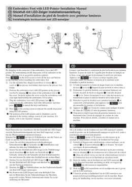
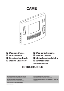
T100 ISTT100 V.3.2007 CS.08406 ENCODER I ISTRUZIONI PER L'INSTALLAZIONE DELLA CENTRALINA ELETTRONICA T 100 (PAG. 1) IL PRESENTE LIBRETTO È DESTINATO AL PERSONALE TECNICO QUALIFICATO ALLE INSTALLAZIONI F INSTRUCTIONS POUR L'INSTALLATION DE LA CENTRALE ELECTRONIQUE T 100 (PAG. CETTE NOTICE S’ADRESSE À DES TECHNICIENS SPÉCIALISÉS DANS L’INSTALLATION E INSTRUCCIONES DE LA CENTRAL ELECTRONICA T 100 (PAG. 17) EL PRESENTE FOLLETTO ESTÁ DESTINADO AL PERSONAL TÉCNICO ESPECIALIZADO EN INSTALACIONES GB D NL INSTRUCTIONS FOR INSTALLING THE ELECTRONIC CONTROL UNIT T 100 (PAG. THIS HANDBOOK IS INTENDED FOR QUALIFIED TECHNICAL INSTALLERS 9) 25) INSTALLATIONSANWEISUNGEN DER ELEKTRONISCHEN STEUEREINHEIT T 100 (PAG. 33) DAS VORLIEGENDE HANDBUCH IST FÜR DAS MIT DER INSTALLATION BETRAUTE TECHNISCH QUALIFIZIERTE FACHPERSONAL BESTIMMT AANWIJZINGEN VOOR DE INSTALLATIE VAN DE ELEKTRONISCHE BESTURINGSKAST T DEZE HANDLEIDING IS BESTEMD VOOR VAKBEKWAME INSTALLATEURS 100 (PAG. 41) Telcoma S.r.l. - via L. Manzoni, 11 - Z.I. Campidui - 31015 Conegliano (TV) Italy Tel. +39 0438 451099 - Fax +39 0438 451102 http://www.telcoma.it E-mail:[email protected] Fig. 1 **FC/SM A= giallo A= jaune A= amarillo A= yellow A= gelb A= geel B= marrone B= marron B= marrón B= brown B= braun B= bruin C-D= verde-bianco C-D= vert-blanc C-D= verde-blanco C-D= green-white C-D= grün-weiß C-D= groen-wit !US 6AC &! ! " # $ - * ANTENNA: se viene usata una scheda radio ad innesto prestare attenzione in quanto su alcuni modelli il connettore per il collegamento dell’antenna è sulla scheda stessa. * ANTENNE: être attentif dans le cas d'utilisation d'une fiche radio embrochable dans la mesure où, sur certains modèles, le connecteur permettant de raccorder l'antenne se trouve sur la fiche même. * ANTENA: Si se utiliza una tarjeta radio de acoplamiento, hay que prestar atención ya que, en algunos modelos, el conector para la conexión de la antena se encuentra en la misma tarjeta. * ANTENNA: pay attention if a plug-in radio card is used, since the connector for antenna connection in certain models is on the actual card. * ANTENNE: wenn eine Steckfunkplatine verwendet wird, ist darauf zu achten, daß sich der Verbinder für den Anschluß an die Antenne bei einigen Modellen auf der Platine selbst befindet. * ANTENNE: Als er een inplugontvanger toegepast wordt moet er opgelet worden omdat bij sommige modellen de connector voor de aansluiting van de antenne op de kaart zelf geplaatst is. Fig. 2 I ISTRUZIONI PER L’INSTALLAZIONE DELLA CENTRALINA ELETTRONICA T100 Prima di eseguire l’installazione consigliamo di leggere attentamente la presente istruzione. Un uso improprio del prodotto o un errore di collegamento potrebbe pregiudicare il corretto funzionamento dello stesso e la sicurezza dell’utente finale. DESCRIZIONE DELLE PARTI (Fig. 1) 1) 2) 3) 4) 5) 6) 7) 8) 9) 10) 11) Pulsante Passo/Passo Pulsante per Programmazione e Stop* Trimmer per regolazione potenza motore Jumper Jp1 (esclusione regolazione potenza motore e soft-start) Morsettiera per collegamento alimentazione ausiliari e spia cancello aperto Led Programmazione (L1) Jumper Test Fusibile 24V 0,3A Fusibile linea 6,3A Morsettiera per collegamento linea alimentazione Morsettiera per collegamento luce cortesia e lampeggiante 12) Morsettiera collegamento motore e condensatore 13) Scheda opzionale antischiacciamento (MAS 100) 14) Reset centralina. Cortocircuitare per un attimo i 2 pin equivale a togliere e ridare la tensione. 15) Scheda radio incorporata compatibile serie Tango 16) Dip-switch funzioni 17) Connettore per inserimento ricevitore 18) Led di segnalazione relativi agli ingressi in morsettiera. Led acceso = ingresso chiuso 19) Morsettiera per collegamento comandi e antenna ricevitore * Questo pulsante di STOP non deve essere considerato di sicurezza ma solo di servizio per facilitare i test durante l’installazione. MODELLI Descrizione modelli della centrale T100: T100 centrale per l'automazione di 1 motore scorrevole o battente, ricevitore incorporato serie TANGO T100F centrale per l'automazione di 1 o 2 motori basculante, ricevitore incorporato serie TANGO T100 SW centrale per l'automazione di 1 motore scorrevole o battente, ricevitore incorporato serie TANGO SW T100F SW centrale per l'automazione di 1 o 2 motori basculante, ricevitore incorporato per la serie TANGO SW Le centraline sono dotate di: - regolazione elettronica della coppia - rallentamento motore - freno motore - controllo funzionamento fotocellule (Foto Test) - autodiagnosi del controllo motore (Triac Test) - sistema antischiacciamento (modulo opzionale MAS 100) La centrale T100 non è adatta a comandare motori con condensatore e finecorsa già cablati direttamente all'interno del motore stesso (es. motori per serrande). 1 I DATI TECNICI U.M. T100 Vac 230 ±10% Frequenza Hz 50/60 Assorbimento stand-by mA 20 Parametri elettrici Alimentazione Assorbimento massimo A 6,3 Potenza max motore VA 1100 temperatura funzionamento °C -20 +60 mm 92x50x161 Modello trasmettitore serie Tango Frequenza di ricezione Mhz 433.920 Nr 140 Dimensione scheda (L x H x P) Parametri radio Capacità di memorizzazione codici ANTISCHIACCIAMENTO Questo modulo opzionale MAS 100 rileva quando il motore viene bloccato meccanicamente e di conseguenza fà eseguire un manovra (per pochi secondi) contraria al senso di marcia. L’intervento viene indicato da alcuni lampeggi del led L1. La manovra (manuale) successiva ad un intervento è contraria a quella che stava eseguendo prima del blocco, ad esempio: se il motore viene bloccato in apertura esegue automaticamente una breve manovra in chiusura e premendo il pulsante P/P riparte in chiusura. - Il sistema antischiacciamento non interviene durante la fase di rallentamento. FOTO TEST Perché il foto test funzioni l’impianto deve prevedere due linee di alimentazione per le fotocellule, la prima collegata ai morsetti 10 e 11 che alimenta i ricevitori e la seconda ai morsetti 12 e 13 che alimenta i trasmettitori (il foto-test deve essere abilitato con il dip-switch n. 7 in posizione ON). La centrale controlla l’efficienza delle fotocellule simulandone un intervento ad ogni inizio manovra. In pratica toglie per un breve istante alimentazione ai trasmettitori e verifica che il ricevitore cambi stato. Se tutto è OK parte il motore e inizia la manovra, se il ricevitore ha qualche problema il ciclo si arresta, e viene segnalato da alcuni lampeggi veloci della spia cancello aperto. - Il foto test funziona anche con la fotocellula 2 (ingresso Jolly) e se vengono collegate più fotocellule con il contatto in serie. - Con il foto test abilitato e la centralina in stand by i trasmettitori delle fotocellule non sono alimentati e l’ingresso FT1 è aperto (led spento). In questa condizione possiamo verificare ugualmente il funzionamento delle fotocellule cortocircuitando il jumper Test (part.7 di Fig 1). 2 I TRIAC TEST Il guasto di questo componente può pregiudicare il funzionamento e la sicurezza dell’impianto. Per questo motivo è stato inserito un controllo prima di ogni manovra. Nel caso in cui ci sia qualche anomalia la centrale si blocca e la spia cancello aperto esegue alcuni lampeggi lenti. SOFT START La funzione soft start fa seguire l’inizio del movimento in modo graduale evitando scossoni al cancello. Questa funzione è comunque escludibile ponticellando Jp1 (part. 4 di Fig. 1). COLLEGAMENTI ELETTRICI Per i collegamenti seguire la tabella 1 e la figura 2. Nel caso di impianti già esistenti e opportuno un controllo generale dello stato dei conduttori (sezione, isolamento, contatti) e delle apparecchiature ausiliarie (fotocellule, riceventi, pulsantiere, selettori chiave, ecc.). Consigli per un corretto impianto: 1. Le condutture entranti nella centralina, nella versione su box stagno, devono essere installate mantenendo possibilmente invariato l'iniziale grado di protezione IP56. 2. La sezione dei cavi deve essere calcolata in base alla loro lunghezza e corrente assorbita. 3. Non usare un cavo unico del tipo "multi-polo" per tutti i collegamenti (linea, motori, comandi, ecc.) o in comune con altre apparecchiature. 4. Dividere l'impianto in almeno due cavi, ad es.: cavo (A) sezione minima conduttori 1.5 mmq - linea alimentazione - linee motori - linea lampeggiante / luce cortesia cavo (B) sezione minima conduttori 0.75 mmq - alimentazione ausiliari - comandi - contatti sicurezza. 5. Quando i cavi di comando presentano tratte molto lunghe (oltre i 50 metri) è consigliabile il disaccoppiamento con dei relè montati vicino alla centralina. 6. Tutti gli ingressi N.C. (fotocellule, finecorsa, costa-fissa e stop) che nella centralina non vengono utilizzati devono essere cortocicuitati con il comune. 7. Tutti i contatti N.C. abbinati ad uno stesso ingresso devono essere collegati in serie. 8. Tutti i contatti N.A. abbinati ad uno stesso ingresso devono essere collegati in parallelo. - Per l’alimentazione della centralina è previsto L’INSERIMENTO DI UN SEZIONATORE esterno (non in dotazione) indipendente e dimensionato secondo il carico. - L'INSTALLAZIONE dell'apparecchiatura deve essere effettuata a "REGOLA D'ARTE" da personale avente i requisiti richiesti dalle leggi vigenti e seguendo le normative EN 12453 e EN 12445 riguardanti la sicurezza dell’automazione. 3 4 Lampada 6 6 9 11 13 14 o 21 14 o 21 14 o 21 14 o 21 14 o 21 14 o 21 23 5 7 8 10 12 15 16 17 18 19 20 22 Acceso da inizio manovra a cancello completamente chiuso. Alimentazione per Tx fotocellula (se viene usata la funzione Fototest). Permanente per alimentazione fotocellule o ausiliari. Collegare alla linea 230Vac. Vedi avvertenze finali. Acceso quando il motore è in azione. Accesa da inizio manovra a 3 minuti dopo la chiusura completa. ATTENZIONE, collegare il condensatore sempre su questi morsetti. NON collegare il condensatore in parallelo al motore! Max 1100VA Max 1100VA NOTE Passo / Passo Stop Fotocellula** Jolly Finecorsa Apre Vedi dip-switch funzioni n.1 e n.2 Blocco di tutte le funzioni. Collegare questo ingresso al comune se non viene utilizzato. Vedi dip-switch funzioni n.3 e n.4 Durante la chiusura inverte la marcia. Collegare questo ingr. al comune se non viene utilizzato. Collegare questo ingresso al comune se non viene utilizzato. Finecorsa Chiude Collegare questo ingresso al comune se non viene utilizzato. 150mA Alimentazione 150mA Spia cancello aperto / Aliment. Alim. centralina Ind. movimento Luce di Cortesia Comune Spunto Motore Chiude Max 1100VA Centrale Calza Per la ricevente incorporata utilizzare un’antenna accordata a 433MHz. Nel caso venga collegata una ricevente al connettore predisposto vedere le caratteristiche dell’antenna richieste dal costruttore. max24V 500mA II° canale ricevitore Disponibile solo se viene inserita una scheda radio bicanale nel connettore predisposto. 24Vac 24Vac 230Vac 6,3A 230Vac 1A 230Vac 1A 230Vac 5A FUNZIONE Apre TAB.1 * ANTENNA: se viene usata una scheda radio ad innesto prestare attenzione in quanto su alcuni modelli il connettore per il collegamento dell’antenna è sulla scheda stessa. ** A fotocellula oscurata e cancello chiuso, se viene inviato un comando, la centrale non esegue l'apertura sino a quando non si libera la fotocellula. Il comando rimane memorizzato nella T100 per 10 secondi, e visualizzato dall’accensione del lampeggiante. Uscita Antenna Rx* 25 Entrata Antenna Rx* 24 Ausiliario Pulsante n.a. Contatto n.c. Contatto n.c. Contatto n.c. o Pulsante n.a. Contatto n.c. Contatto n.c. Ausiliari Spia / Ausiliari Linea Lampeggiante Motore 4 230Vac 5A Condensatore 0 1 230Vac 5A I max Motore V 2 DISPOSITIVO 230Vac 5A MOR. n. Motore MOR. n. 3 I 6 7 8 9 10 Prelampeggio Richiusura Fototest Freno Rallentamento Radio incorporata OFF ON Un intervento costa fissa inverte la marcia per pochi secondi. Dopo un intervento costa fissa la centralina si blocca, la richiusura viene annullata. Usare un contatto N.C. Chiudendo l’ ingresso cortocircuitato verso il comune il cancello si apre e rimane aperto fino a quando non si riapre il contatto. Usare un contatto N.A. Sia in apertura che in chiusura l’intervento di questa fotocellula blocca il cancello fino a quando non viene ripristinata. La manovra successiva è sempre un’apertura. Usare un contatto N.C. Il cancello esegue un’apertura parziale per un tempo fisso pari a 6 secondi. Usare un pulsante N.A. Il lampeggiante viene alimentato contemporaneamente con il motore. Il lampeggiante viene alimentato 5 secondi prima di ogni manovra. Dopo una apertura completa la centrale richiude solo con un comando manuale. Dopo una apertura completa la centrale richiude dopo il tempo pausa programmato. Vedi testo al capitolo Fototest. Vedi testo al capitolo Fototest. Dove non è strettamente necessario è consigliabile escludere il freno. Il freno motore serve a vincere l’inerzia di automazioni pesanti. Quando il freno è abilitato interviene ad ogni fine manovra. Non viene eseguito il rallentamento nella parte finale della corsa. Con il rallentamento inserito il motore in prossimità di ogni fine manovra dimezza la sua velocità. Quando NON viene usata la ricevente incorporata, SI deve escluderla. Abilitazione della ricevente incorporata. Costa Fissa Orologio Fotocellula Pedonale Escluso Inserito Escluso Inserito Escluso Inserito Escluso Inserito Escluso Inserito Escluso Inserito Escluso comando in apertura Apre - Chiude Durante l’apertura premendo il pulsante P/P non abbiamo nessun effetto. Durante la pausa premendo il pulsante P/P il cancello chiude. Durante la chiusura premendo il pulsante P/P il cancello si blocca per pochi secondi e poi apre. Durante l’apertura premendo il pulsante P/P non abbiamo nessun effetto. Durante la pausa premendo il pulsante P/P non abbiamo nessun effetto. Durante la chiusura premendo il pulsante P/P il cancello si blocca per pochi secondi e poi apre. Apre Funzione condominiale Durante l’apertura premendo il pulsante P/P il cancello si blocca per pochi secondi e poi chiude. Durante la chiusura premendo il pulsante P/P il cancello si blocca per pochi secondi e poi apre. Apre - Chiude NOTE Durante l’apertura premendo il pulsante P/P il cancello si blocca, premendo nuovamente chiude. Durante la chiusura premendo il pulsante P/P il cancello si blocca, premendo nuovamente apre. DESCRIZIONE Apre - Stop - Chiude Nota: la configurazione iniziale standard è raffigurata nel part. 16 di fig. 1 5 Modo Ingresso Jolly 1 2 1 2 1 2 1 2 n.Dip 3 4 3 4 3 4 3 4 Modo Ingresso Passo / Passo Canale Radio FUNZIONE I TAB.2 5 I IMPOSTAZIONE FUNZIONI (tab. 2) Le varie opzioni descritte sono selezionabili con il dip-switch funzioni (part. 16 di fig.1). - Si tenga presente che per far apprendere una variazione delle impostazioni alla centrale dobbiamo togliere e ridare per un istante l’alimentazione, oppure cortocircuitare per un attimo i 2 pin di reset della centralina. Il trimmer PW (part. 3 di fig.1) regola la potenza del motore (ruotandolo in senso orario la potenza aumenta). Se la potenza viene regolata troppo bassa può succedere che intervenga la protezione antischiacciamento. - La regolazione PW non viene considerata ad ogni inizio manovra dove viene data piena potenza per qualche secondo (spunto) e durante la fase di rallentamento. PROGRAMMAZIONE TEMPI LAVORO E PAUSA La centrale auto-apprende i tempi di lavoro e pausa durante la manovra di programmazione. Si possono riassumere due tipologie di impianto e modalità diverse: 1) Impianto con finecorsa elettrici. Durante la programmazione l’intervento del finecorsa determina il limite di manovra del cancello. 2) Impianto con battute di arresto. Durante la programmazione l’intervento della scheda antischiacciamento (se inserita) determina il limite di manovra del cancello. - Nel caso non vi siano i finecorsa elettrici e la scheda antischiacciamento inserita, i tempi devono essere impostati mediante l’azionamento del comando P/P. Prima della programmazione: A. Portare il cancello o il portone a metà corsa. B. Alimentare la centrale e verificare il corretto funzionamento degli ingressi comando tramite i relativi led (i contatti nc. devono avere il led acceso). C. Se i trasmettitori delle fotocellule sono alimentati con l’uscita spia (mors. 12 e 13) verificarne il funzionamento cortocircuitando il jumper Test (part. 7 di fig.1). D. Liberare la zona di movimento del cancello. Programmazione: - Togliere alimentazione alla centrale - Alimentare la centrale tenendo premuto il tasto PROG.(part.2 di fig.1) per almeno 5 sec. Si accende il led programmazione L1. La stessa funzione può essere fatta premendo il tasto PROG, cortocircuitare per un attimo i pin reset e tenere premuto il tasto PROG sino a quando si accende il led L1. - Premere il pulsante P/P per avviare la manovra. - Durante la programmazione il pulsante P/P sulla scheda, i pulsanti collegati all’ingresso P/P e il radiocomando eseguono la stessa funzione. - Il cancello esegue una manovra di accostamento in chiusura. Se la prima è una manovra di apertura bloccare la programmazione con uno stop e invertire AP e CH del del motore. Verificare anche il corretto verso dei finecorsa se installati. Ripetere ancora la procedura. - Quando il cancello arriva in chiusura deve trovare una battuta di arresto, oppure se installato, il finecorsa. - Dopo una breve pausa il cancello parte in apertura. - Quando il cancello arriva in apertura deve trovare una battuta di arresto, oppure se installato, il finecorsa. - A questo punto (il cancello è aperto) lasciamo trascorrere il tempo di pausa desiderato e poi premiamo il pulsante P/P. 6 I - Se non interessa la richiusura automatica possiamo premere subito il pulsante P/P. - Il cancello esegue la chiusura. - Fine della programmazione il led L1 si spegne. PROGRAMMAZIONE RADIO La ricevente a bordo auto-apprende i codici della serie TANGO. Per memorizzare i trasmettitori procedere come segue: - Alimentare la centrale - Assicurarsi che il dip-switch funzioni n.10 sia in posizione ON. - Premere brevemente il pulsante Stop/Prog. (Part.2 di fig. 1) sulla base e il led L1 inizia a lampeggiare. - Trasmettere con il telecomando da programmare. - Se il led L1 esegue un lampeggio più lungo vuol dire che la memorizzazione è andata a buon fine. - Se il codice e già presente in memoria, il led L1 fa dei brevi lampeggi. - È possibile resettare la memoria dei codici tenendo premuto per circa 10 secondi il pulsante Stop/Prog. sino a quando si accende L1. - Nel caso non venga usata questa ricevente a bordo, SI DEVE escluderla spostando il dip-switch 10 in posizione OFF. COLLEGAMENTO PARALLELO DI 2 MOTORI Nel caso si debba collegare 2 motori (ad esempio nelle installazioni per aperture con porte basculanti), collegare in parallelo direttamente sulla morsettiera della T100 i 2 motori ed i 2 condensatori. RALLENTAMENTO Se su un’installazione dove si usi la funzione di rallentamento, durante il passaggio da velocità normale a rallentata si avvertissero dei contraccolpi al cancello, si può cambiare modalità di passaggio eseguendo queste manovre: A - togliere alimentazione. B - premere contemporaneamente i pulsanti PP e STOP/PROG sulla centralina (part. 1 e 2 di fig. 1). C - ridare alimentazione, tenendo premuti i pulsanti. D - il led L1 (part. 6 di fig. 1) dà una breve segnalazione dell’avvenuto passaggio. Per ritornare alla configurazione iniziale, ripetere semplicemente le stesse manovre sopra descritte. Nelle versioni T100F e T100F SW per l'automazione basculanti, la funzione di rallentamento se inserita, viene fatta solo durante la fase di chiusura. Inoltre quando interviene il finecorsa chiude, o finisce il tempo di lavoro in chiusura, la centrale continua a dare alimentazione al motore per ancora circa un secondo. NUOVE FUNZIONI T100 - T100SW 1) FUNZIONE ENCODER (solo su alcune versioni) I nuovi motori scorrevoli Telcoma mod. SML hanno di serie un’uscita encoder compatibile con le ultime centraline T100, T100SW. Vantaggi utilizzando questi nuovi prodotti: - rilevamento ostacoli durante tutta la corsa del cancello(normativa EN 12445) - precisione nel movimento (l’encoder rileva il reale movimento del cancello) 7 I - precisione zona di rallentamento - possibilità di funzionamento (senza rilevazione ostacoli) anche con motori sprovvisti di encoder Installazione e collaudo impianti con encoder Collegare l’encoder del motore al connettore 3 poli che si trova vicino al trimmer PW, la centrale rileva automaticamente il collegamento e fa lampeggiare il led L1 durante la programmazione. Se il led non lampeggia la centralina funziona con i parametri a tempo (come modelli precedenti). Regolazione potenza motore Secondo la normativa EN 12445 ogni automazione deve superare le prove d’impatto misurate con l’apposito strumento. Eseguire le prove di impatto e variare la coppia del motore agendo sul trimmer PW (particolare 3 di fig. 1). Se questo non fosse sufficiente per rientrare nel grafico indicato dalle normative consigliamo di installare un profilo in gomma morbida in testa al cancello in modo da attutire l’impatto. Se regolando la coppia del motore e montando il profilo in gomma non si riesce ancora a soddisfare la normativa è obbligatorio montare dei dispositivi alternativi ad esempio una costa sensibile sul bordo mobile del cancello. 2) FUNZIONE CHIUSURA DOPO FOTOCELLULA Abilitando questa funzione la centralina riduce la pausa a 2 secondi dopo un intervento fotocellula (FT1). Procedura per abilitare la funzione fotocellula: - togliere togliere alimentazione alla centralina - ridare alimentazione mantenendo premuto il pulsante Stop/prog. - dopo 3 secondi si accende il led L1 - mantenendo premuto il pulsante Stop/prog. premere brevemente il pulsante P/P - il led L1 inizia a lampeggiare - mantenendo sempre premuto il pulsante Stop/prog e dando degli impulsi al pulsante P/P il led cambia lampeggio - lampeggi veloci la funzione chiusura dopo fotocellula è abilitata - lampeggi lenti funzione disabilitata - dopo aver scelto rilasciare il pulsante Stop/Prog, la centrale memorizza e avvia il funzionamento normale. 3) SPIA CANCELLO APERTO Nei modelli precedenti l’uscita mors. 12-13 poteva comandare sia la spia che il fototest, mantenendo lo stesso funzionamento. La spia si accendeva a inizio ciclo e si spegneva quando il cancello si chiudeva completamente. Se l’impianto non prevedeva il foto-test era obbligatorio portare il dip 7 in OFF. Le nuove centrali hanno una doppia possibilità: A) impianti senza foto-test (dip 7 Off) L’uscita mors.12-13 funziona come spia di stato cancello - in apertura lampeggio lento - in chiusura lampeggio veloce - in pausa (in attesa di richiudere) doppio lampeggio con pausa di 1 secondo - in situazione di blocco permanente (stop, costa o anti-schiacciamento) luce fissa B) impianti con foto-test (dip 7 On) Collegare l’alimentazione dei trasmettitori delle fotocellule all’uscita 12-13. In parallelo è possibile collegare una spia con il funzionamento semplificato (modelli precedenti). ATTENZIONE: se non si usa il fototest NON collegare i trasmettitori delle fotocellule all’uscita 12-13. Nel caso si voglia sostituire una centrale esistente che è una versione precedente fare attenzione appunto al collegamento delle fotocellule e controllare che rispetti quanto sopra. 8 I COLLAUDO FINALE Eseguire sempre un collaudo finale dopo aver eseguito tutte le varie programmazioni. - Controllare il corretto funzionamento dei dispositivi di protezione (sistema antischiacciamento, pulsante stop, fotocellule, coste sensibili, ecc.) - Controllare il corretto funzionameneto dei dispositivi di segnalazione (lampeggianti, spia cancello aperto, ecc.). - Controllare il corretto funzionamento dei dispositivi di comando (pulsante P/P, telecomandi, ecc.) . AVVERTENZE IMPORTANTI SULL’INSTALLAZIONE - L’installazione dell’automazione deve essere eseguita a regola d’arte da personale qualificato avente i requisiti di legge e fatta in conformità della direttiva macchine 98/37/CE e alle normative EN13241-1, EN 12453 e EN 12445. - Verificare la solidità delle strutture esistenti (colonne, cerniere, ante) in relazione alle forze sviluppate dal motore. - Verificare che vi siano dei fermi meccanici di adeguata robustezza a fine apertura e fine chiusura delle ante. - Verificare lo stato di eventuali cavi già presenti nell’impianto. - Fare un’analisi dei rischi dell’automazione e di conseguenza adottare le sicurezze e le segnalazioni necessarie. - Installare i comandi (ad esempio il selettore a chiave) in modo che l’utilizzatore non si trovi in una zona pericolosa. - Terminata l’installazione provare più volte i dispositivi di sicurezza, segnalazione e di sblocco dell’automazione. - Applicare sull’automazione l’etichetta o la targhetta CE contenenti le informazioni di pericolo e i dati di identificazione. - Consegnare all’utilizzatore finale le istruzioni d’uso, le avvertenze per la sicurezza e la dichiarazione CE di conformità. - Accertarsi che l’utilizzatore abbia compreso il corretto funzionamento automatico, manuale e di emergenza dell’automazione. - Informare l’utilizzatore per iscritto (ad esempio nelle istruzioni d’uso) : dell’eventuale presenza di rischi residui non protetti e dell’uso improprio prevedibile. Di scollegare l’alimentazione quando viene eseguita la pulizia nell’area dell’automazione o viene fatta piccola manutenzione (es: ridipingere). Di controllare frequentemente che non vi siano danni visibili all’automazione e nel caso ve ne siano, avvertire immediatamente l’installatore Di non far giocare i bambini nelle immediate vicinanze dell’automazione - Predisporre un piano di manutenzione dell’impianto (almeno ogni 6 mesi per le sicurezze) riportando su di un apposito registro gli interventi eseguiti. La ditta TELCOMA Srl si riserva la facoltà insindacabile di apportare, in qualsiasi momento, le modifiche che si rendessero necessarie ai fini di un miglioramento estetico e/o funzionale. 9 I SMALTIMENTO Questo prodotto è formato da vari componenti che potrebbero a loro volta contenere sostanze inquinanti. Non disperdere nell’ambiente! Informarsi sul sistema di riciclaggio o smaltimento del prodotto attenendosi alle norme di legge vigenti a livello locale. Dichiarazione di Conformità CE Secondo Direttiva 1999/5/CE (R&TTE) Il sottoscritto Augusto Silvio Brunello, Legale rappresentante della ditta: TELCOMA S.r.l. Via L. Manzoni 11, 31015 Conegliano (TV) ITALY Dichiara che il prodotto: Tipo: Centralina Modello: T100 Impiego: Centralina per apricancello È conforme ai requisiti essenziali dell'articolo 3 ed ai relativi provvedimenti della Direttiva 1999/5/CE, se impiegato per gli usi preposti. È conforme ai requisiti di sicurezza e protezione della salute, Articolo 3.1.a Norme applicate: EN 60950 È conforme ai requisiti di protezione relativi alla compatibilità elettromagnetica, Articolo3.1.b Norme applicate: EN 301 489-3 È conforme all'efficienza di immissione radio frequenza nello spettro, Articolo 3.2 Norme applicate: ETSI EN 300 220-3 Luogo e data: Conegliano, 01/03/2005 Legale rappresentante Augusto Silvio Brunello 10 F INSTRUCTIONS POUR L’INSTALLATION DE LA CENTRALE ELECTRONIQUE T100 Ces instructions doivent être lues attentivement avant de commencer l'installation. Un usage impropre du produit ou une erreur de connexion pourraient compromettre le bon fonctionnement de ce dernier et mettre en danger son utilisateur. DESIGNATION PARTS FIG. 1 1) 2) 3) 4) 5) 6) 7) 8) 9) 10) 11) Bouton Pas à Pas Bouton pour Programmation et Stop* Trimmer puissance moteur Jumper Jp1 (exclusion réglage puissance moteur et soft-start) Bornier du branchement des alimentations auxiliaires et du voyant portail ouvert Led Programmation (L1) Jumper test Fusible 24V 0,3A Fusible ligne 5,3A Bornier du branchement de la ligne d'alimentation Bornier du branchement de l'éclairage de fonc- tionnement et de la lampe clignotante 12) Bornier du branchement du moteur et du condensateur 13) Carte optionnelle anti-écrasement (MAS 100) 14) Réinitialisation centrale. Court-circuiter un instant les deux broches équivaut à couper la tension et à la redonner. 15) Carte radio intégrée comp. avec série Tango 16) Dip-switch de fonctions 17) Connecteur pour récepteur emrochable 18) Led de signalisation concernant les entrées du bornier. Led allumé = entrée fermée 19) Bornier du branchement des commandes et de l'antenne du récepteur *Le bouton STOP ne doit pas être considéré celui de sécurité mais de service afin de faciliter les essais pendant l'installation. MODELES Description modèles de la centrale T100: T100 centrale permettant de commander 1 moteur pour l'automatisation de portails coulissants ou battants, récepteur intégré série TANGO. T100F centrale permettant de commander 1 ou 2 moteurs pour l'automatisation de portes basculantes, récepteur intégré série TANGO. T100 SW centrale permettant de commander 1 moteur pour l'automatisation de portails coulissants ou battants, récepteur intégré série TANGO SW. T100F SW centrale permettant de commander 1 ou 2 moteurs pour l'automatisation de portes basculantes, récepteur intégré pour la série TANGO SW. Les centrales sont dotées de: - régulation électronique du couple - ralentissement du moteur - frein moteur - contrôle du fonctionnement de la photocellule (Photo Test) - auto-diagnostic du contrôle moteur (Triac Test) - système d'anti-écrasement (optionelle MAS 100) La centrale T100 n'est pas en mesure de commander des moteurs dont le condensateur et le fin de course sont déjà câblés directement à l'intérieur du moteur même (ex. moteurs pour rideaux de magasins). 11 F DONNÉES TECHNIQUES U.M. T100 Vac 230 ±10% Fréquence Hz 50/60 Absorption stand-by mA 20 Paramètres électriques Alimentation Absorption max. A 6,3 Puissance max. moteur VA 1100 Température de fonc. °C -20 +60 mm 92x50x161 Modèle émetteur serie Tango Fréquence de réception Mhz 433.920 Nr 140 Dimensions carte (L x H x P) Paramètres radio Nombre de codes ANTI-ÉCRASEMENT Ce contrôle relève le blocage mécanique du moteur et par conséquent il fait exécuter (pour quelques secondes) la manœuvre contraire au sens de marche. L'intervention est indiquée par les clignotements de la led L1. La manœuvre (manuelle) successive à l'intervention est contraire à celle avant le blocage. Par exemple, si le moteur est bloqué en ouverture, il fait automatiquement une manœuvre brève en fermeture. L'appui du bouton P/P referme le portail. - Anti-écrasement n'intervient pas en phase de ralentissement. PHOTO TEST Pour que le photo-test fonctionne, le site doit prévoir deux lignes d'alimentation des photocellules. La première (celle qui alimente les récepteurs) est branchée sur les borniers 10 et 11 et la seconde (celle qui alimente les émetteurs) est branchée sur les borniers 12 et 13 (le dip switch 7 doit être en position On quand on active le photo-test). Le coffret contrôle l'efficacité des photocellules en simulant leur intervention au début de la manœuvre. Il coupe l'alimentation aux émetteurs et vérifie si le récepteur change d'état. Le moteur part et la manœuvre commence; en cas des problèmes avec le récepteur, le cycle s'arrête et le voyant portail ouvert clignote. - Le photo test fonctionne aussi bien avec la photocellule 2 (entrée Jolly) et en cas où plus photocellules sont branchées avec le contact en série. - Quand le photo test est actif et le coffret est en stand-by, les émetteurs des photocellules ne sont pas alimentés et la sortie FT1 est ouverte (la led est éteinte). Dans cette condition il est possible de vérifier également le fonctionnement des photocellules en court-circuitant le jumper Test (part.7 fig.1). 12 F TRIAC TEST La panne de ce composant peut compromettre le fonctionnement du site et sa sécurité. Pour cette raison un contrôle a été prévu avant chaque manœuvre. En présence d'anomalies, la centrale se bloque et le voyant portail ouvert effectue quelques clignotements lents. SOFT START La fonction soft fait effectuer un début de mouvement progressif au portail en évitant ainsi les secousses. Cette fonction peut être exclue en shuntant Jp1 (détail 4 de Fig. 1). BRANCHEMENTS ELECTRIQUES Pour les branchements suivre le tableau 1 et la figure 2. Dans les cas des sites existants un contrôle général des conducteurs est opportun (section, isolement, contacts) et des appareils auxiliaires (photocellules, récepteurs, pulsatoire, sélecteur à clé, etc.). Conseils pour un site correct: 1. Les conduites qui entrent dans le coffret (version box d'étang), doivent être installées sans compromettre si possible l'indice de protection IP56. 2. La section des câbles doit être calculée en fonction de leur longueur et du courent absorbé. 3. Ne pas utiliser un câble unique de type "multipolaire" pour tous les branchements (ligne, moteurs, commandes, etc.) ou bien en commun avec d'autres appareils. 4. Diviser le site en deux câbles au moins, par exemple: le câble (A) section minimum conducteur 1.5mm2 - ligne alimentation - lignes moteurs - ligne lampe clignotante/éclairage de fonctionnement le câble (B) section minimum conducteur 0.75mm2 - alimentation auxiliaire - commandes - contact de sécurité. 5. Quand les câbles de commande sont des fils très longs (plus de 50m), les découplages avec des relais montés près du coffret sont recommandables. 6. Toutes les entrées N.C.(photocellules, fin de course, barre palpeuse et stop) non utilisées doivent être court-circuitées avec la borne commune. 7. Tous les contacts N.C. associés à la même entrée doivent être branchés en série. 8. Tous les contacts N.O. associés à la même entrée doivent branchés en parallèle. - Pour l'alimentation du coffret L'INSERTION D'UN SECTIONNEUR extérieur (pas fourni) indépendant et dimensionné selon la capacité du moteur est prévue. - La mise en œuvre de la motorisation doit être effectuée par le personnel possédant les qualifications requises par les lois en vigueur et répondre aux conditions de sécurité des normes EN 12453 et EN12445. 13 14 Lampe 6 6 9 11 13 14 o 21 14 o 21 14 o 21 14 o 21 14 o 21 14 o 21 23 5 7 8 10 12 15 16 17 18 19 20 22 Antenne Rx* 25 Allumée dès le début de la manœuvre jusqu'à la fermeture complète du portail. Alimentation pour Tx cellule photoélectrique, si la fonction Fototest est utilisée. Démarrage moteur permanent pour alimentation cellules photoélectriques ou auxiliaires. Brancher à 230Vac, Voir les avertissements finaux. Il est allumé quand le moteur est en marche. Allumé dès le début de la manœuvre à 3 minutes après la fermeture complète. ATTENTION, connecter toujours le condensateur sur ces bornes. NE jamais connecter le condensateur parallèlement au moteur! Max 1100VA Max 1100VA NOTE Pas à pas Stop Photocellule** Jolly Voir dip-switch n.1 et n.2 Bloque toutes les fonctionsBrancher cette entrée sur la commune si elle n'est pas utilisée Voir dip switch fonctions n.3 et n.4.Si cette entrée n'est pas utilisée, mettre ces dip switches en ON. Pendant la fermeture cette fonction invertit la marche.Brancher cette entrée sur la commune si elle n'est pas utilisée Fin de course ouvre Brancher cette entrée sur la commune si elle n'est pas utilisée. Fin de course ferme Brancher cette entrée sur la commune si elle n'est pas utilisée. 150mA Alimentation 150mA Voyant portail ouvert/Alimentat. Aliment. coffret Ind. de mouvem. Eclairage de fonction Commune Démarrage moteur Ferme Max 1100VA Centrale Tresse Pour le récepteur intégré utiliser une antenne accordée à 433MHz. En cas où un récepteur soit branché sur le connecteur prévu, voir les caractéristiques de l'antenne requise par le constructeur. max24V 500mA Récepteur II canal Cette fonction n'est disponible qu'en cas où la carte radio à deux canaux est insérée sur le connecteur prévu. 24Vac 24Vac 230Vac 6,3A FONCTION Ouvre * ANTENNE : si l'on utilise une carte radio embrochable, faire attention au connecteur car sur certains modèles le connecteur pour brancher l'antenne se trouve sur la carte. ** Si une commande est envoyée alors que la cellule photoélectrique est couverte et que le portail est fermé, la centrale n'effectue pas l'ouverture tant que la cellule photoélectrique n'est pas dégagée. Le clignotant reste allumé pendant 10 secondes tant que la commande reste mémorisée dans la T100. Sortie Antenne Rx* Auxiliaire Poussoir n.o. Contact n.c. Contact n.c. Contact n.c. ou bien le poussoir n.o. Contact n.c. Contact n.c. Auxiliaires Voyant / Auxiliaires Ligne 24 Entrée 230Vac 1A 230Vac 5A Lampe clignotante 230Vac 1A Moteur 4 230Vac 5A Condensateur 0 1 230Vac 5A I max Moteur V 2 DISPOSITIF 230Vac 5A Born. N. Moteur Born. N. 3 F TAB.1 6 7 8 9 10 Re fermeture Phototest Frein Ralentissement Radio integrée OFF ON En fermant l'entrée court-circuitée sur la commune, le portail s'ouvre et reste ouvert jusqu'à quand le contact ne s'ouvre.Utiliser un contact n.o. Soit en ouverture soit en fermeture l'intervention de cette photocellule bloque le portail jusqu'à quand la photocellule ne reprenne ses conditions initiales. La manœuvre successive est toujours en ouverture. Utiliser un contact n.c. Le portail exécute l'ouverture partielle pour une période fixe de 6 sec. Utiliser un poussoir n.o. La lampe clignotante est alimentée contemporainement au moteur. Temporisateur Photocellule 2 Piétons Exclu Actif Exclu Actif Exclu Actif Exclu Actif Exclu Actif Exclu Actif L'activation du récepteur intégré. Si le récepteur intégré n'est pas utilisé, il est nécessaire de l'exclure. En cas où le ralentissement est activé, le moteur réduit de moitié sa vitesse. Le ralentissement est absent à la fin de la course. Le frein du moteur sert à combattre l'inertie des motorisations lourdes. Quand le frein est actif, il intervient à la fin de chaque manœuvre. Il est conseillable d'exclure le frein où il n'est pas rigoureusement nécessaire. Voir le texte p.3. Voir le texte p.3 Après l'ouverture complète le coffret referme après une pause programmée. Après l'ouverture complète le coffret referme avec une seule commande manuelle. La lampe clignotante est alimentée 5sec. avant chaque manœuvre. Son intervention invertit la marche pour quelques instants.Après son intervention le coffret se bloque, la re fermeture est annulée. Utiliser un contact n.c. Barre palpeuse (exclusion commande en ouvert.) Ouvre - ferme Pendant l'ouverture, l'appui du bouton P/P n'a aucun effet.Pendant la pause, l'appui du bouton P/P ferme le portail. Pendant la fermeture en appuyant le bouton P/P on bloque le portail. Au bout de quelques instants le portail s'ouvre. Pendant l'ouverture, l'appui du bouton P/P n'a aucun effet.Pendant la pause, l'appui du bouton P/P n'a aucun effet.Pendant la fermeture en appuyant le bouton P/P le portail se bloque, au bout de quelques instants il s'ouvre. Ouvre Fonction immeuble Pendant l'ouverture, l'appui du bouton P/P bloque le portail. Au bout de quelques instants le portail se ferme. Pendant la fermeture l'appui du bouton P/P bloque le portail pour quelques instants, après le portail s'ouvre. Ouvre - ferme NOTE Pendant l'ouverture, en appuyant le bouton P/P on bloque le portail; le second appui ferme le portail. Pendant la fermeture en appuyant le bouton P/P le portail se bloque; le second appui ouvre le portail. DESCRIPTION Ouvre - Stop - Ferme REMARQUE: la configuration initiale standard est représentée sur le détail 16 de fig. 1 5 3 4 3 4 3 4 3 4 1 2 1 2 1 2 1 2 n.Dip Préavis Mode entrée Jolly Mode entrée Pas à pas et radio canal FONCTION F TAB.2 15 F PROGRAMMATION DES FONCTIONS (tab. 2) De différentes options peuvent être sélectionnées avec les dip-switches de fonctions. (part.16 fig.1). - Ne pas oublier qu'il est nécessaire, pour que la centrale puisse apprendre une variation des réglages, de couper la tension pendant un instant et de la redonner ou de court-circuiter un instant les deux broches de réinitialisation de la centrale. Le trimmer PW (part.3 fig.1) règle la puissance du moteur (en rotant dans le sens des aiguilles, la puissance augmente). Si la puissance réglée est trop basse, la protection Anti-crush peut intervenir. - Le réglage PW n'est pas considéré au commencement de chaque manœuvre (démarrage moteur) où la puissance est au maximum pour quelques secondes et en phase de ralentissement. PROGRAMMATION DES TEMPS DE TRAVAIL ET DE TEMPS DE PAUSE Le coffret auto-apprend les temps de travail et ceux de pause pendant l'action de programmation. Selon leur modalité, les installations peuvent être classifiées en deux types différents: 1) Installations avec les fins de course électriques L'intervention des fins de course lors de la programmation détermine la limite de manœuvre du portail. 2) Installations avec les arrêts mécaniques. L'intervention de la carte anti-écrasement (si elle est insérée) lors de la programmation détermine la limite de manœuvre du portail. - Si la fiche anti-écrasement est introduite et s'il n'y a pas de fins de courses électriques, les temps doivent être programmés en actionnant la commande P/P. Avant la programmation A. Mettre le portail au milieu de sa course. B. Alimenter le coffret et vérifier le fonctionnement correct des sorties au moyen des leds relatives (la led des contacts nc doit être allumée). C. Si les émetteurs des photocellules sont alimentés par la sortie voyant (bornes. 12 et 13), vérifier le fonctionnement en court-circuitant le pontet Test (part.7 fig.1). D. Libérer la zone du mouvement du portail. Programmation - Couper l'alimentation du coffret - Alimenter le coffret en maintenant appuyé le bouton PROG. (part.2 fig.1) pour 5 sec au moins. La led de programmation L1 s'allume. La même fonction peut être obtenue en pressant la touche PROG, courtcircuiter un instant les broches de réinitialisation et maintenir la touche PROG pressée jusqu'à ce que le led L1 s'allume. - Appuyer sur le bouton P/P pour commencer la programmation. - Pendant la programmation le bouton P/P sur la carte, les boutons branchés à la sortie P/P et la radio commande accomplissent la même fonction. - Le portail effectue le mouvement en fermeture. Si le premier mouvement se fait dans le sens ouverture, bloquer la programmation avec un stop et invertir OUVR. et FERM. du moteur. Vérifier aussi le sens des fins de course (si installés). - Au moment où le portail se ferme, il doit trouver les arrêts mécaniques ou bien le fin de course (si installé). - Au bout du temps de pause brève, le portail fait le mouvement dans le sens ouverture. - Pour que le portail s'arrête ouvert, il doit trouver les arrêts mécaniques ou bien le fin de course (si installé). - A ce point (le portail est ouvert) on laisse passer le temps de pause désiré et puis, appuyer sur le bouton P/P. 16 F - Si l'on n'utilise pas la fermeture automatique il faut appuyer immédiatement sur le bouton P/P. - Le portail se ferme. - La fin de la programmation: la led L1 s'éteint. PROGRAMMATION RADIO Le récepteur à bord auto-apprend les codes de la série TANGO. Pour mémoriser les émetteurs procéder comme suit : - Alimenter le coffret - S'assurer que le cavalier de fonction N°10 soit en position ON - Appuyer brièvement sur le bouton Stop/Prog. (part.2, fig.1), la led L1 commence à clignoter. - Lors du clignotement appuyer sur le bouton de l'émetteur que vous voulez mémoriser. - Le clignotement long de la led L1 confirme la mémorisation. - Si le code est déjà présent dans la mémoire, le led L1 clignote brièvement. - Des codes peuvent être effacés de la mémoire en maintenant la touche Stop/Prog. pressée pendant environ 10 secondes jusqu'à ce que le led L1 s'allume. - En cas où le récepteur à bord n'est pas utilisé, il est recommandable de l'exclure en déplaçant le dip switch 10 en OFF. CONNEXION PARALLELE DE 2 MOTEURS Si deux moteurs doivent être connectés (par exemple sur les installations pour ouvertures à portes basculantes), connecter les 2 moteurs et les 2 condensateurs en parallèle directement sur le bornier de la T100. RALENTISSEMENT Si, sur une installation où l'on utilise la fonction de ralentissement, le portail subi des contrecoups pendant le passage de la vitesse normale à une vitesse ralentie, on peut changer le mode de passage en effectuant les manœuvres suivantes: A - couper l'alimentation B - presser simultanément les poussoirs PP et STOP sur la centrale (détail 1 et 2 de fig. 1) C - alimenter de nouveau en tenant les touches pressées. D - le led L1 (détail 6 de fig. 1) signale brièvement que le passage a été effectué. Pour retourner à la configuration initiale, répéter simplement les manœuvres décrites ci-dessus. Dans les versions T100F et T100F SW pour l'automatisation de portes basculantes, la fonction de ralentissement, si elle a été validée, ne produit son effet que pendant la phase de fermeture. Par ailleurs, quand le fin de course en fermeture intervient ou le temps de la manœuvre de fermeture s'est écoulé, la centrale continue à alimenter le moteur pendant encore une seconde environ. NOUVELLES FONCTIONS T100 - T100SW 1) FONCTION ENCODEUR (sur certaines versions seulement) Les nouveaux moteurs coulissants Telcoma mod. SML possèdent, de série, une sortie encodeur compatIble avec les dernières centrales T100, T100SW. Avantages offerts par ces nouveaux produits: - détection de l’obstacle sur toute la course du portail (normative EN 12445) - précision du mouvement (l’encodeur détecte le mouvement réel du portail) 17 F - précision zone de ralentissement - possibilité de fonctionnement (sans détection obstacles) également avec des moteurs sans encodeur Installation et essai des installations dotées d’encodeur Connecter l’encodeur du moteur au connecteur 3 pôles qui se trouve près du PW, la centrale détecte automatiquement la connexion et fait clignoter le L1 pendant la programmation. Si le led ne clignote pas, la centrale fonctionne avec des paramètres basés sur le temps (comme sur les modèles précédents). Réglage puissance moteur Selon la normative EN 12445 chaque automation doit passer avec succès les essais au choc mesurés à l’aide d’un instrument spécial. Effectuer les essais au choc puis modifier le couple du moteur en agissant sur le trimmer PW (détail 3 de fig. 1). Si cela ne suffit pas pour rentrer dans les limites indiquées par les normatives, il est conseillé d’installer un bord en caoutchouc souple en tête de portail de manière à atténuer le choc. Si le réglage de la sensibilité et l’installation du bord en caoutchouc ne permettent toujours pas de rentrer dans les valeurs indiquées, il est obligatoire d’installer d’autres types de dispositifs comme, par exemple, une tranche de sécurité sur le bord mobile du portail. 2) FONCTION DE FERMETURE APRES LA CELLULE PHOTOELECTRIQUE Si cette fonction est activée, la centrale réduit la pause à 2 secondes après une intervention de la cellule photoélectrique (FT1). Procédure permettant d’activer la fonction cellule photoélectrique: - couper le courant à la centrale - alimenter de nouveau la centrale en maintenant la touche Stop/prog pressée. - le led L1 s’allume après 3 secondes - presser brièvement la touche P/P en maintenant la touche Stop/prog. pressée - le led L1 commence à clignoter - le fait de maintenir la touche Stop/prog. pressée et de donner de brèves impulsions à la touche P/P modifie le clignotement du led - une première impulsion sur la touche P/P entraîne des clignotements rapides : la fonction de fermeture après la cellule photoélectrique est activée - une deuxième impulsion sur la touche P/P entraîne des clignotements lents : la fonction est désactivée - une fois le choix effectué, arrêter de presser la touche Stop/Prog, la centrale mémorise et entame un fonctionnement normal. 3) VOYANT PORTAIL OUVERT Sur les modèles précédents, la sortie bornes 12-13 pouvait commander aussi bien le voyant que le phototest en maintenant le même fonctionnement. Le voyant s’allumait au début du cycle et s’éteignait lorsque le portail se fermait complètement. Si l’installation n’était pas dotée d’un photo-test, il était obligatoire de placer le dip 7 en OFF. Les nouvelles centrales ont une double possibilité: Installations sans photo-test (dip 7 Off) La sortie bornes 12-13 a une fonction de voyant de l’état du portail - en ouverture, clignotement lent - en fermeture, clignotement rapide - en pause (avant de refermer) double clignotement avec pause d’1 seconde - en situation de blocage permanent (stop, tranche ou anti-écrasement) lumière fixe Installations avec photo-test (dip 7 On) Connecter l’alimentation des émetteurs des cellules photoélectriques à la sortie 12-13. Il est possible de connecter en parallèle un voyant au fonctionnement simplifié (modèles précédents). ATTENTION: si le photo-test n’est pas utilisé, NE PAS connecter les émetteurs des cellules photoélectriques à la sortie 12-13. Si une centrale déjà existante (version précédente) doit être remplacée, il est nécessaire de s’assurer que la connexion des cellules photoélectriques respecte les indications susdites. 18 F ESSAIS FINAUX Effectuer toujours le test final après avoir conclu les programmations. - Contrôler le fonctionnement correct des dispositifs de protection (système anti-écrasement, bouton stop, photocellules, barre palpeuse, etc.) - Contrôler le fonctionnement correct des dispositifs de signalisation (lampe clignotante, voyant portail ouvert, etc.). - Contrôler le fonctionnement correct des dispositifs de commande (bouton P/P, émetteurs, etc.). AVERTISSEMENTS IMPORTANTS CONCERNANT L’INSTALLATION - L’installation de l’automation doit être effectuée dans les règles de l’art par du personnel spécialisé, conformément aux dispositions légales, à la directive machine 98/37/CE et aux normes EN 12453 et EN 12445. - S’assurer que les structures existantes (colonnes, charnières, vantaux) soient suffisamment solides pour résister aux forces développées par le moteur. - S’assurer que les arrêts mécaniques en fin d’ouverture et en fin de fermeture des vantaux soient suffisamment robustes. - Vérifier l’état des câbles qui se trouvent éventuellement déjà dans l’installation - Faire une analyse des risques de l’automation et adopter, en fonction de celle-ci, les dispositifs de sécurité et de signalisation nécessaires. - Installer les commandes (par exemple le sélecteur à clé) de manière à ce que l’utilisateur ne se trouve pas dans une zone dangereuse. - Une fois l’installation terminée, tester plusieurs fois les dispositifs de sécurité, de signalisation et de déverrouillage de l’automation. - Appliquer sur l’automation l’étiquette ou la plaque CE où sont indiqués les dangers présentés par l’automation ainsi que les données d’identification de la machine. - Remettre à l’utilisateur final le mode d’emploi, les avertissements concernant la sécurité et la déclaration CE de conformité. - S’assurer que l’utilisateur a bien compris le fonctionnement automatique, manuel et d’urgence de l’automation. - Informer par écrit l’utilisateur (par exemple dans le mode d’emploi) de l’éventuelle présence de risques résiduels non couverts et des utilisations impropres prévisibles. - Informer l’utilisateur par écrit (par exemple dans le mode d’emploi) : de la présence éventuelle de risques résiduels non protégés et de l’usage impropre prévisible. De la nécessité de couper l’alimentation quand le nettoyage de la zone de l’automatisme a lieu ou en cas de petites interventions de maintenance (ex. repeindre). De la nécessité de contrôler fréquemment l’absence de dommages visibles à l’automatisme et s’il y en a, avertir immédiatement l’installateur. Qu’il ne faut pas laisser les enfants jouer à proximité de l’automatisme. - Etablir un plan de maintenance de l’installation (au moins tous les 6 mois pour les dispositifs de sécurité) en inscrivant sur un registre prévu à cet effet les interventions effectuées. L'enterprise TELCOMA S.r.l. se réserve le droit absolu d'apporter à tout moment à ses prodouits des modifications visant à les améliorer d'un point de vue esthétique et/ou fonctionel. 19 F MISE AU REBUT Ce produit est constitué de divers composants qui pourraient à leur tour contenir des substances polluantes. Ne pas jeter dans la nature! S’informer sur le système de recyclage ou de mise au rebut du produit en respectant les normes locales en vigueur. Déclaration de conformité CE Selon Directive 1999/5/CE (R&TTE) Le soussigné Augusto Silvio Brunello, Représentant légal de la société: TELCOMA S.r.l. Via L. Manzoni 11, 31015 Conegliano (TV) ITALIE Déclare que le produit: Type: Coffret Modèle: T100 Emploi : Coffret pour motorisation des portails Est conforme aux impératifs essentiels de l'article 3 et aux dispositions de la Directive 1999/5/CE, s'il est employé pour les usages désignés. Est conforme aux impératifs de sécurité et de protection de la santé, Article 3.1.a Normes appliquées: EN 60950 Est conforme aux impératifs de protection relative à la compatibilité électromagnétique, Article 3.1.b Normes appliquées : EN 301 489-3 Est conforme à l'efficacité d'émission radio fréquence dans le spectre, Article 3.2 Normes appliquées : ETSI EN 300 220-3 Lieu et date Conegliano, 01/03/2005 Représentant légal Augusto Silvio Brunello 20 E INSTRUCCIONES DE LA CENTRAL ELECTRONICA T 100 Antes de realizar la instalación, se aconseja leer atentamente las presentes instrucciones. Un uso impropio del producto o un error de conexión podría comprometer el correcto funcionamiento del mismo y la seguridad del usuario final. DESCRIPCION DE LAS PIEZAS DE LA Fig. 1 1) 2) 3) 4) 5) 6) 7) 8) 9) 10) 11) Botón Paso/Paso Botón para Programación y Stop* Trimmer para potencia motor Puente de conexión Jp1 (exclusión regulación potencia motor y soft start) Tablero de bornes para conexión alimentación auxiliares y luz de aviso de cancela abierta Led Programación (L1) Jumper Test Fusible 24 V - 0,3 A Fusible de línea 6,5 A Tablero de bornes para conexión línea alimentación Tablero de bornes para conexión luz interior y luz intermitente 12) Tablero de bornes para conexión motor y condensador 13) Tarjeta opcional antiaplastamiento (MAS 100) 14) Reactivación de la central de mando. Cortocircuitar un momento los 2 pins equivale a cortar y volver a dar el suministro de corriente. 15) Tarjeta radio incorporada compatible serie Tango 16) Dip-switches funciones 17) Conector para introducción receptor 18) Leds de señalización relativos a las entradas en el tablero de bornes. Led encendido = entrada cerrada 19) Tablero de bornes para conexión mandos y antena del receptor * Este botón de STOP no debe considerarse de seguridad, sino sólo de servicio, para facilitar los tests durante la instalación. MODELOS Descripción de los modelos de la central T100: T100 Central para la automatización de 1 motor para cancelas correderas o batientes, receptor incorporado serie TANGO. T100F Central para la automatización de 1 ó 2 motores para puertas basculantes, receptor incorporado serie TANGO. T100 SW Central para la automatización de 1 motor para cancelas correderas o batientes, receptor incorporado serie TANGO SW. T100F SW Central para la automatización de 1 ó 2 motores para puertas basculantes, receptor incorporado serie TANGO SW. Las centrales están provistas de: - Regulación electrónica del par - Deceleración del motor - Freno del motor - Control del funcionamiento de las fotocélulas (Foto Test) - Autodiagnóstico del control del motor (Triac Test) - Sistema antiaplastamiento (opcional MAS 100) La central T100 no es adecuada para controlar motores con condensador y fines de carrera ya cableados directamente dentro del motor (ej.: motores para cierres metálicos). 21 E DATOS TECNICOS U.M. T100 Vac 230 ±10% Frecuencia Hz 50/60 Absorción stand-by mA 20 Parámetros eléctricos Alimentación Absorción máxima A 6,3 Potencia máx. motor VA 1100 Temperatura de funcionamiento °C -20 +60 mm 92x50x161 Modelo transmisor serie Tango Frecuencia de recepción Mhz 433.920 Nr 140 Dimensiones tarjeta (ANCH. x ALT. x PROF.) Parámetros radio Capacidad de memorización ANTIAPLASTAMIENTO Este control detecta cuándo el motor es bloqueado mecánicamente y, en consecuencia, hace ejecutar una maniobra (durante pocos segundos) contraria al sentido de marcha. La intervención se indica con algunos parpadeos del led L1. La maniobra (manual) sucesiva a una intervención es contraria a la que se estaba ejecutando antes del bloqueo; por ejemplo, si el motor es bloqueado en fase de apertura, ejecuta automáticamente una breve maniobra de cierre y, pulsando el botón P/P, reemprende la marcha cerrando. - El antiaplastamiento no interviene durante la fase de deceleración. FOTO TEST Para que el foto test funcione, la instalación debe prever dos líneas de alimentación para las fotocélulas: la primera, conectada a los bornes 10 y 11, alimenta a los receptores, y la segunda, conectada a los bornes 12 y 13, alimenta a los transmisores (el foto-test debe estar habilitado, con el dip-switch n° 7 en posición ON). La central controla la eficiencia de las fotocélulas simulando una intervención de las mismas cada vez que se inicia una maniobra. De hecho, corta, por un breve instante, la alimentación a los transmisores y controla que el receptor cambie de estado. Si todo es OK, el motor se pone en marcha y empieza la maniobra; si el receptor tiene algún problema, el ciclo se interrumpe, señalándose la situación con algunos parpadeos de la luz de aviso de cancela abierta. - El foto test funciona también con la fotocélula 2 (entrada Jolly) y, si se conectan más fotocélulas, con el contacto en serie. - Con el foto test habilitado y la central de mando en stand by, los transmisores de las fotocélulas no son alimentados y la entrada FT1 está abierta (led apagado). En esta condición, es posible verificar, igualmente, el funcionamiento de las fotocélulas cortocircuitando el jumper Test (pieza 7 de la Fig 1). 22 E TRIAC TEST La avería de este componente puede comprometer el funcionamiento y la seguridad de la instalación. Por este motivo, se ha introducido un control antes de cada maniobra. En caso de que se produzca alguna anomalía, la central se bloquea y la luz de aviso de cancela abierta ejecuta algunos parpadeos lentos. SOFT START La función soft start hace ejecutar el inicio del movimiento de manera gradual, evitando sacudidas a la cancela. Esta función, en cualquier caso, puede excluirse puenteando Jp1 (n° 4 de la Fig. 1). CONEXIONES ELECTRICAS Para las conexiones, es preciso seguir la tabla 1 y la figura 2. En el caso de instalaciones ya existentes, es oportuno efectuar un control general del estado de los conductores (sección, aislamiento, contactos) y de los dispositivos auxiliares (fotocélulas, receptores, botoneras, selectores de llave, etc.). Consejos para una correcta instalación: 1. Los conductos que entran en la central de mando, en la versión con caja estanca, deben instalarse manteniendo invariable, posiblemente, el grado de protección inicial IP56. 2. La sección de los cables debe calcularse en base a su longitud y a la corriente absorbida por los mismos. 3. No debe usarse un cable único de tipo multipolar para todas las conexiones (línea, motores, mandos, etc.) o en común con otros equipos. 4. Hay que dividir la instalación al menos en dos cables, por ej.: cable (A) sección mínima conductores: 1,5 mm_ - línea alimentación - líneas motores - línea luz intermitente / luz interior cable (B) sección mínima conductores: 0,75 mm_ - alimentación auxiliares - mandos - contactos seguridad. 5. Cuando los cables de mando presenten tramos muy largos (más de 50 metros), es aconsejable el desacoplamiento con relés montados cerca de la central de mando. 6. Todas las entradas N.C. (fotocélulas, fines de carrera, barra fija y stop) que no sean utilizadas en la central de mando deben cortocicuitarse con el común. 7. Todos los contactos N.C. acoplados a una misma entrada deben conectarse en serie. 8. Todos los contactos N.A. acoplados a una misma entrada deben conectarse en paralelo. - Para la alimentación de la central de mando, está prevista LA INTRODUCCION DE UN SECCIONADOR exterior (no asignado en el equipamiento base), independiente y dimensionado según la carga. - LA INSTALACION del equipo debe ser efectuada, "SEGUN LOS CANONES", por personal que reúna los requisitos impuestos por las leyes vigentes y siguiendo las normativas EN 12453 y EN 12445 relativas a la seguridad de los automatismos. 23 24 Lámpara 6 6 9 11 13 14 o 21 14 o 21 14 o 21 14 o 21 14 o 21 14 o 21 23 5 7 8 10 12 15 16 17 18 19 20 22 Máx. 1100 VA Encendido cuando el motor está en función. Encendida desde el inicio de la maniobra hasta 3 minutos después del cierre completo. ATENCION: Conecte el condensador siempre a estos bornes. ¡NO conecte el condensador en paralelo al motor! Máx. 1100 VA NOTE Encendida desde el inicio de la maniobra hasta el cierre completo de la cancela. Alimentación para Tx fotocélula, si se utiliza la función Fototest. Central Trenza max24V 500mA II° canal Receptor Paso/Paso Stop Fotocélula** Jolly Fin de carrera Abre Para el receptor incorporado, es preciso utilizar una antena sintonizada a 433 MHz. En caso de que se conecte un receptor al conector predispuesto, véanse las características de la antena requeridas por el constructor. Disponible únicamente si se monta una tarjeta radio bicanal en el conector predispuesto. Véanse los dip-switches funciones n° 1 y n° 2. Bloqueo de todas las funciones. Conectar esta entrada al común, si no se utiliza. Véanse los dip-switches funciones n° 3 y n° 4. Si no se utiliza esta entrada, hay que poner los dips n° 3 y n° 4 en ON. Durante la fase de cierre, invierte la marcha. Conectar esta entrada al común, si no se utiliza. Conectar esta entrada al común, si no se utiliza Fin de carrera Cierra Conectar esta entrada al común, si no se utiliza. cancela abierta / Alimentación Permanente para la alimentación de las fotocélulas o de los dispositivos auxiliares. Alim. central de mando Conectar a la línea 230 V c.a.. Véanse las advertencias finales. Ind. de movimiento Luz interior Común Toma de fuerza mot. Cierra Máx. 1100 VA * ANTENA: Si se utiliza una tarjeta radio de acoplamiento, hay que prestar una particular atención, pues, en algunos modelos, el conector para la conexión de la antena se encuentra en la misma tarjeta. ** Con la fotocélula oscurecida y la cancela cerrada, si se envía un comando, la central no ejecuta la apertura hasta que la fotocélula quede libre. El comando permanece memorizado en la T100 durante 10 segundos y se visualiza con el encendido de la luz intermitente. Salida Antena Receptor* 25 Entrada Antena Receptor* 24 Auxiliar Botón n.a. Contacto n.c. Contacto n.c. Contacto n.c. o Botón n.a. Contacto n.c. Contacto n.c. FUNCIÓN Abre 150mA Alimentación 150mA Luz de aviso de 230Vac 6,3A 230Vac 1A 230Vac 1A 230Vac 5A Auxiliares 24Vac Luz de aviso de 24Vac cancela abierta / Auxiliares Línea Luz intermitente Motor 4 230Vac 5A Condensador 0 1 230Vac 5A I max Motor V 2 DISPOSITIVO 230Vac 5A MOR. n. Motor MOR. n. 3 E TAB.1 6 7 8 9 10 Cierre Automático Fototest Freno Deceleración Radio incorp. OFF ON Abre – Cierra Cerrando la entrada cortocircuitada hacia el común, la cancela se abre y permanece abierta hasta que el contacto se vuelva a abrir.Úsese un contacto N.A. Tanto en fase de apertura como de cierre, la intervención de esta fotocélula bloquea la cancela hasta que la misma sea reactivada. La maniobra sucesiva es siempre de apertura. Úsese un contacto N.C. La cancela ejecuta una maniobra de apertura parcial durante un tiempo fijo de 6 segundos. Úsese un botón N.A. La luz intermitente es alimentada al mismo tiempo que el motor. La luz intermitente es alimentada 5 segundos antes de cada maniobra. Después de una maniobra de apertura completa, la central cierra únicamente con un comando manual. Después de una maniobra de apertura completa, la central cierra después del tiempo de pausa programado. Véase el texto del punto 3. Véase el texto del punto 3. Cuando no sea estrictamente necesario, es aconsejable excluir el freno. El freno del motor sirve para vencer la inercia de automatismos pesados. Cuando el freno está habilitado, interviene al final de cada maniobra. No se ejecuta la deceleración en la parte final de la carrera. Con la deceleración activada, el motor, al acercarse cada final de maniobra, reduce a la mitad su velocidad. Cuando NO se utilice el receptor incorporado, éste DEBE excluirse. Habilitación del receptor incorporado. Fotocélula 2 Apertura Peatonal Excluido Activado Excluido Activado Excluido Activado Excluido Activado Excluido Activado Excluido Activado Una intervención de la barra fija invierte la marcha durante algunos segundos. Después de una intervención de la barra fija, la central de mando se bloquea y el cierre autom. resulta anulado. Úsese un contacto N.C. Reloj Barra Fija (Exclusión mando de apertura) Durante la fase de apertura, pulsando el botón P/P, no tenemos ningún efecto. Durante la pausa, pulsando el botón P/P, la cancela se cierra. Durante la fase de cierre, pulsando el botón P/P la cancela se bloquea durante algunos segundos y después se abre. Durante la fase de apertura, pulsando el botón P/P, no tenemos ningún efecto. Durante la pausa, pulsando el botón P/P, no tenemos ningún efecto. Durante la fase de cierre, pulsando el botón P/P, la cancela se bloquea durante algunos segundos y después se abre. Abre Función colectiva Durante la fase de apertura, pulsando el botón P/P, la cancela se bloquea durante algunos segundos y después se cierra. Durante la fase de cierre, pulsando el botón P/P, la cancela se bloquea durante algunos segundos y después se abre. Abre – Cierra NOTE Durante la fase de apertura, pulsando el botón P/P, la cancela se bloquea; apretándolo de nuevo, se cierra. Durante la fase de cierre, pulsando el botón P/P, la cancela se bloquea; apretándolo de nuevo, se abre. DESCRIPCIÓN Abre – Stop – Cierra Nota: La configuración inicial estándar está representada en el n° 16 de la Fig. 1 5 3 4 3 4 3 4 3 4 1 2 1 2 1 2 1 2 n.Dip Parpadeo previo Modo Entrada Jolly Modo Entrada Paso / Paso Canal Radio FUNCIÓN E TAB.2 25 E CONFIGURACION DE LAS FUNCIONES (tab. 2) Las diversas opciones descritas en la tabla pueden seleccionarse con el dip-switch funciones (pieza 16 de la fig. 1). - Téngase en cuenta que, para que la central memorice una variación de las configuraciones, es preciso cortar y restablecer, un momento, el suministro de corriente, o bien cortocircuitar un instante los 2 pins de reactivación de la central. El trimmer PW (pieza 3 de la fig. 1) regula la potencia del motor (girándolo en el sentido de las agujas del reloj, la potencia aumenta). Si la potencia se regula demasiado baja, puede suceder que intervenga la protección Anti-crush. - La regulación PW es ignorada al inicio de cada maniobra, donde se da plena potencia durante algunos segundos (toma de fuerza), y durante la fase de deceleración. PROGRAMACION DE LOS TIEMPOS DE TRABAJO y PAUSA La central autoaprende los tiempos de trabajo y pausa durante la maniobra de programación. Se pueden resumir dos tipos de instalación y modalidades diversas: 1) Instalación con fines de carrera eléctricos. Durante la programación, la intervención de los fines de carrera determina el límite de maniobra de la cancela. 2) Instalación con topes. Durante la programación, la intervención de la tarjeta Anti-crush (si está montada) determina el límite de maniobra de la cancela. - En caso de que no se hayan montado los fines de carrera eléctricos ni la tarjeta antiaplastamiento, los tiempos deben configurarse accionando el mando P/P. Antes de la programación: Es preciso: A. Llevar la cancela o la puerta hasta la mitad de la carrera. B. Alimentar la central y controlar el correcto funcionamiento de las entradas de mando mediante los respectivos leds (los contactos nc. deben tener el led encendido). C. Si los transmisores de las fotocélulas son alimentados con la salida luz de aviso de cancela abierta (bornes 12 y 13), controlar el funcionamiento cortocircuitando el jumper Test (pieza 7 de la fig. 1). D. Dejar libre la zona de movimiento de la cancela. Programación: Es preciso: - Cortar el suministro de corriente a la central. - Alimentar la central manteniendo presionada la tecla PROG. (pieza 2 de la fig. 1) al menos 5 s. Se encenderá el led de programación L1. La misma función puede obtenerse presionando la tecla PROG; hay que cortocircuitar un momento los pins de reactivación y mantener presionada la tecla PROG hasta que se encienda el led L1. - Pulsar el botón P/P para iniciar la maniobra. - Durante la programación, el botón P/P de la tarjeta, los botones conectados a la entrada P/P y el radiomando ejecutan la misma función. - La cancela ejecuta una maniobra de acercamiento en fase de cierre. Si la primera maniobra es de apertura, hay que bloquear la programación con un stop e invertir AP y CH del motor. Es preciso controlar, también, el correcto sentido de los fines de carrera, si están instalados. - Cuando la cancela llega al final de la fase de cierre, debe encontrar un tope, o bien, si ha sido instalado, el fin de carrera correspondiente. - Después de una breve pausa, la cancela se abre. - Cuando la cancela llega al final de la fase de apertura, debe encontrar un tope, o bien, si ha sido insta26 E lado, el fin de carrera correspondiente. - Llegados aquí (la cancela está abierta), hay que dejar transcurrir el tiempo de pausa deseado y, seguidamente, pulsar el botón P/P. - Si no interesa el cierre automático, se puede pulsar enseguida el botón P/P. - La cancela ejecuta la fase de cierre. - Fin de la programación: el led L1 se apaga. PROGRAMACION RADIO El receptor incorporado autoaprende los códigos de la serie TANGO. Para memorizar los transmisores, hay que realizar lo siguiente: - Alimentar la central. - Asegurarse de que el dip-switch funciones n° 10 se encuentre en posición ON. - Pulsar brevemente el botón Stop/Prog. (Pieza 2 de la fig. 1) de la central: el led L1 empieza a parpadear. - Transmitir con el Mando a distancia que se desea programar. - Si el led L1 efectúa un parpadeo más largo, quiere decir que la memorización se ha realizado con éxito. - Si el código ya está presente en la memoria, el led L1 emite unos breves parpadeos. - Es posible reactivar la memoria de los códigos manteniendo pulsado, durante aproximadamente 10 segundos, el botón Stop/Prog., hasta que se encienda el led L1. - En caso de que este receptor incorporado no sea utilizado, DEBERA excluirse poniendo el dip-switch 10 en la posición OFF. CONEXIÓN PARALELA DE 2 MOTORES En caso de que se deban conectar 2 motores (por ejemplo, en las instalaciones para aperturas con puertas basculantes), es preciso conectar en paralelo, directamente en el tablero de bornes de T100, los 2 motores y los 2 condensadores. CONEXIÓN PARALELA DE 2 MOTORES Deceleración Si, en una instalación donde se utilice la función de deceleración, durante el cambio de velocidad normal a velocidad reducida, se notan contragolpes en la cancela, es posible cambiar la modalidad de cambio ejecutando estas maniobras: A. Cortar el suministro de corriente. B. Pulsar, a la vez, los botones PP y STOP de la central de mando (piezas 1 y 2 de la fig. 1). C. restablecer el suministro de corriente, manteniendo pulsados los botones. D. El led L1 (pieza 6 de la fig. 1) da una breve indicación del cambio efectuado. Para volver a la configuración inicial, simplemente hay que repetir las mismas maniobras arriba descritas. En las versiones T100F y T100F SW, para la automatización de puertas basculantes, la función de deceleración, si está incluida, se ejecuta únicamente durante la fase de cierre. Además, cuando interviene el fin de carrera de cierre o cuando termina el tiempo de trabajo en fase de cierre, la central sigue dando alimentación al motor durante aproximadamente un segundo. NUEVAS FUNCIONES T100 - T100SW 1) FUNCION ENCODER (sólo para algunas versiones). Los nuevos motores para cancelas correderas Telcoma mod. SML tienen, como configuración predefinida, una salida para encoder compatible con las últimas centrales de mando T100 y T100SW. Ventajas al utilizar estos nuevos productos: 27 E - detección de obstáculos durante toda la carrera de la cancela (normativa EN 12445) - precisión en el movimiento (el encoder detecta el movimiento real de la cancela) - precisión en la zona de deceleración - posibilidad de funcionamiento (sin detección de obstáculos) incluso con motores desprovistos de encoder Instalación y prueba de equipos con encoder Conecte el encoder del motor al conector de 3 polos que se encuentra cerca del trimmer PW: la central de mando detecta automáticamente la conexión y hace parpadear el led L1 durante la programación. Si el led no parpadea, la central funciona con los parámetros temporales (como en los modelos anteriores). Regulación de la potencia del motor De conformidad con la normativa EN 12445, todo automatismo debe superar las pruebas de impacto medidas con el instrumento específico. Ejecute las pruebas de impacto y varíe el par del motor por medio del trimmer PW (pieza 3 de la fig. 1). Si esto no fuera suficiente para entrar en el gráfico indicado por las normas, aconsejamos instalar un perfil de goma blanda en el extremo de la cancela para amortiguar el impacto. Si, regulando el par del motor y montando el perfil de goma, todavía no se consigue satisfacer la normativa, es obligatorio montar dispositivos alternativos como, por ejemplo, una barra sensible en el borde móvil de la cancela. 2) FUNCION DE CIERRE DESPUES DE LA INTERVENCION DE LA FOTOCELULA Habilitando esta función, la central de mando reduce la pausa a 2 segundos después de una intervención de la fotocélula (FT1). Procedimiento para habilitar la función Fotocélula: - Corte el suministro de energía a la central de mando. - Restablezca el suministro de energía manteniendo pulsado el botón Stop/prog.: - al cabo de 3 segundos, se encenderá el led L1. - Manteniendo pulsado el botón Stop/prog., apriete brevemente el botón P/P: - el led L1 empezará a parpadear. - Manteniendo pulsado el botón Stop/prog y dando impulsos al botón P/P, el led cambiará la modalidad de parpadeo: - parpadeos rápidos: la función de cierre después de la intervención de la fotocélula está habilitada, - parpadeos lentos: función excluida. - Una vez escogida la opción deseada, suelte el botón Stop/Prog: la central de mando memoriza y pone en marcha el funcionamiento normal. 3) INDICADOR LUMINOSO DE CANCELA ABIERTA En los modelos anteriores, la salida de los bornes 12-13 podía controlar tanto el indicador luminoso como el Foto-test, manteniendo el mismo funcionamiento. El indicador luminoso se encendía al comienzo del ciclo y se apagaba cuando la cancela se cerraba completamente. Si la instalación no preveía el Foto-test, era obligatorio poner el dip 7 en OFF. Las nuevas centrales de mando tienen una doble posibilidad: instalaciones sin Foto-test (dip 7 en Off) La salida de los bornes12-13 funciona como indicador luminoso del estado de la cancela: - en fase de apertura, parpadeo lento - en fase de cierre, parpadeo rápido - en pausa (en espera de volver a cerrar), doble parpadeo con pausa de 1 segundo - en situación de bloqueo permanente (stop, borde final de seguridad o antiaplastamiento), luz fija instalaciones con Foto-test (dip 7 en On) Conecte la alimentación de los transmisores de las fotocélulas a la salida 12-13. En paralelo, es posible conectar un indicador luminoso con el funcionamiento simplificado (modelos anteriores). ATENCION: Si no se usa el Foto-test, NO conecte los transmisores de las fotocélulas a la salida 1213. En caso de que se desee sustituir una central de mando existente que es una versión anterior, proceda, con atención, a la conexión de las fotocélulas y controle que respete lo indicado arriba. 28 E PRUEBA FINAL Una vez terminadas todas las programaciones, es necesario realizar, siempre, una prueba final, que consiste en lo siguiente: - Controlar el correcto funcionamiento de los dispositivos de protección (sistema anti-crush, botón de stop, fotocélulas, barras sensibles, etc.). - Controlar el correcto funcionamiento de los dispositivos de señalización (luces intermitentes, luz de aviso de cancela abierta, etc.). - Controlar el correcto funcionamiento de los dispositivos de mando (botón P/P, mandos a distancia, etc.). ADVERTENCIAS IMPORTANTES SOBRE LA INSTALACION - La instalación del automatismo debe ser realizada según los cánones, por personal cualificado que reúna los requisitos establecidos por la ley y de conformidad con la Directiva sobre máquinas 98/37/CE y con las normas EN 12453 y EN 12445. - Compruebe la solidez de las estructuras existentes (columnas, bisagras, hojas) en relación con las fuerzas desarrolladas por el motor. - Controle que haya retenes mecánicos de solidez adecuada en los puntos de fin de apertura y de fin de cierre de las hojas. - Controle el estado de los cables ya existentes en la instalación, en su caso. - Haga un análisis de los riesgos del automatismo y adopte los dispositivos de seguridad y las señalizaciones necesarias en consecuencia. - Instale los mandos (por ejemplo, el selector de llave) de manera que el usuario no se encuentre en una zona peligrosa. - Terminada la instalación, pruebe varias veces los dispositivos de seguridad, señalización y desbloqueo del automatismo. - Aplique en el automatismo una etiqueta o una placa CE que contenga las informaciones de peligro y los datos de identificación. - Entregue al usuario final las instrucciones para el uso, las advertencias para la seguridad y la declaración CE de conformidad. - Asegúrese de que el usuario haya comprendido el correcto funcionamiento automático, manual y de emergencia del automatismo. - Informe al usuario por escrito (por ejemplo, en los manuales de instrucciones) de la eventual presencia de riesgos residuales no protegidos y del uso inadecuado previsible. - Informe al usuario por escrito (por ejemplo en las instrucciones de uso) : sobre la presencia de riesgos residuales no protegidos y sobre el uso inadecuado previsible. que debe desconectar la alimentación cuando hace la limpieza en la zona de la automatización o si hace un pequeño mantenimiento (ej.: pintar). que debe controlar a menudo que la automatización no presente daños visibles y, en el caso de que los haya, deberá advertir de inmediato al instalador que no debe permitir que los niños jueguen en las cercanías de la automatización Predisponga un programa de mantenimiento de la instalación (al menos cada 6 meses para los dispositivos de seguridad), anotando en un registro expresamente dedicado las intervenciones realizadas. La empresa TELCOMA Srl se reserva la facultad indiscutible de aportar, en cualquier momento, las modificaciones que considere necesarias para una mejora estética y/o funcional de sus productos. 29 E ELIMINACIÒN Este producto está formado de varios componentes que, a su vez, podrían contener sustancias contaminantes. ¡No los abandone en el medio ambiente! Infórmese sobre el sistema de reciclaje o eliminación del producto, respetando las normas vigentes locales. Declaración de Conformidad CE según la Directiva 1999/5/CE (R&TTE) El infrascrito Augusto Silvio Brunello, Representante legal de la empresa: TELCOMA S.r.l., dirección Via L. Manzoni 11, 31015 Conegliano (TV), ITALIA, declara que el producto: Tipo: Central de mando Modelo: T100 Empleo: Central de mando para abrecancela Es conforme a los requisitos esenciales del artículo 3 y a las correspondientes disposiciones de la Directiva 1999/5/ CE, si se utiliza para los usos previstos. Es conforme a los requisitos de seguridad y protección de la salud, Artículo 3.1.a. Normas aplicadas: EN 60950 Es conforme a los requisitos de protección relativos a la compatibilidad electromagnética, Artículo 3.1.b. Normas aplicadas: EN 301 489-3 Es conforme a la eficacia de introducción de radiofrecuencias en el espectro, Artículo 3.2. Normas aplicadas: ETSI EN 300 220-3 Lugar y fecha: en Conegliano, 01/03/2005 Representante legal Augusto Silvio Brunello 30 GB INSTRUCTIONS FOR INSTALLING THE ELECTRONIC CONTROL UNIT T 100 Please read these instructions carefully before installing the control unit. Improper use or a connection error could jeopardise correct operation of the product and endanger the end user. DESCRIPTION OF PARTS in Fig. 1 1) 2) 3) 4) 5) 6) 7) 8) 9) 10) 11) Step-by-step (P/P) pushbutton Programming and Stop* pushbutton Trimmer for motor power Jumper Jp1 (soft-start and motor power adjustment bypass) Terminal board for auxiliaries power supply and gate open warning light connection Programming of LED (L1) Jumper test Fuse 24V 0.3A Line fuse 6,3A Terminal board for power supply line connection Terminal board for courtesy and flashing light connection 12) Terminal board for motor and capacitor connection 13) Optional Anti-crush card (MAS 100) 14) Control unit reset. Short-circuiting the 2 pins for a moment is equivalent to cutting off and reconnecting to the power supply. 15) Incorporated radio card compatible w. Tango range 16) Functions dip switches 17) Connector for receiver connection 18) Indicator lights (LED) related to the terminal board inputs. LED on = input closed 19) Terminal board for receiver antenna and controls connection * This STOP button is not a safety button but serves solely to facilitate tests during installation. MODELS Description of T100 control unit models: T100 control unit for sliding or swing gate automation with 1 motor, incorporated TANGO range receiver T100F control unit for overhead door automation with 1 or 2 motors, incorporated TANGO range receiver T100 SW control unit for sliding or swing gate automation with 1 motor, incorporated TANGO SW range receiver T100F SW control unit for overhead door automation with 1 or 2 motors, incorporated TANGO SW range receiver The control units are equipped with: - electronic torque regulation - motor slowdown - motor brake - photo test - Triac test (motor control self-diagnosis) - anti-crushing system (optional MAS 100) The T100 control unit is unsuitable for controlling motors with condenser and limit switch already wired directly inside the actual motor (e.g. motors for roller shutters). 31 GB TECHNICAL DATA U.M. T100 Vac 230 ±10% Frequency Hz 50/60 Stand-by input mA 20 Electrical parameters: Power supply Maximum input A 6,3 Max. motor power VA 1100 Working temperature °C -20 +60 mm 92x50x161 Transmitter model serie Tango Reception frequency Mhz 433.920 Nr 140 Card size (W x H x D) Radio parameters: Storage capacity ANTI-CRUSH This control detects when the motor is mechanically jammed and consequently commands a reverse movement (for a few seconds), which is indicated by the LED (indicator light) L1 blinking several times. The next movement (manual) after the above activation continues in the reverse direction to that prior to jamming; for example, if the motor jams during gate opening, it automatically makes a short closing movement and upon pressing the P/P button the gate continues closing. - The anti-crushing device does not activate during the slowdown stage. PHOTO TEST For the photo test to work, the system must have two power supply lines for the photocells, the first being connected to terminals 10 and 11, which power the receivers, and the second to terminals 12 and 13, which power the transmitters (the photo test must be enabled with dip-switch No. 7 in the ON position). The control unit checks the efficiency of the photocells by simulating an activation at every start of gate movement. In practice, it cuts off the power supply for an instant to the transmitters and checks that the receiver changes status. If everything is OK the motor starts up, thereby starting the gate movement; if the receiver has any problems the cycle stops and the open gate light blinks several times to warn of the situation. - The photo test also works with photocell 2 (Jolly input) and if several photocells are connected in series with the contact. - With the photo test enabled and the control unit in standby, the photocell transmitters are not powered and the FT1 input is open (LED off). Operation of the photocells may still be checked in this condition by short-circuiting the test jumper (part 7 of Fig 1). 32 GB TRIAC TEST Failure of this component could jeopardise installation operation and safety. That is why a control prior to every gate movement has been inserted. Should there by any malfunction, the control unit locks and the open gate warning light blinks slowly. SOFT START The soft-start function determines a gradual start of movement without jolts on the gate. This function may in any case be bypassed by inserting the jumper Jp1 (part 4 of Fig. 1). ELECTRICAL CONNECTIONS For connections, refer to table 1 and figure 2. With existing installations, a general check of the state of the wires (section, insulation, contacts) and auxiliary equipment (photocells, receivers, pushbutton boards, key selectors, etc.) is recommended. Tips for correct installation: 1. The wires entering the control unit, in the sealed box version, should be connected without altering the initial protection rating IP56 if possible. 2. The cross section of the cables should be calculated according to their length and absorbed current. 3. Do not use a single cable of the “multi-core” type for all the connections (line, motors, controls, etc.) or in common with other equipment. 4. Use at least two cables for the installation, e.g.: cable (A) minimum wire section 1.5 sq.mm - power supply line – motor lines - courtesy/flashing light line cable (B) minimum wire section 0.75 sq.mm - auxiliaries power supply - controls – safety contacts. 5. When the control cables are very long (over 50 metres), de-coupling is advisable with relays mounted near the control unit. 6. Any N.C. inputs (photocells, limit switches, fixed safety edge and stops) that are not used in the control unit should be short-circuited with the common terminal terminal. 7. All the N.C. contacts linked with the same input should be connected in series. 8. All the N.O. contacts linked with the same input should be connected in parallel. - THE INSERTION OF AN external, independent DISCONNECTING SWITCH (not supplied) of suitable capacity for the load is envisaged for the control unit power supply. - The equipment should be INSTALLED in a "WORKMANLIKE" manner by qualified personnel in accordance with the laws in force and in compliance with standards EN 12453 and EN 12445 regarding automation safety. 33 34 Light 6 6 9 11 13 14 o 21 14 o 21 14 o 21 14 o 21 14 o 21 14 o 21 23 5 7 8 10 12 15 16 17 18 19 20 22 On, from start of movement to full closure of gate. Permanent for power supply of photocells or auxiliaries. Connect to the 230Vac line. See final recommendations On, when motor is working. On, from start of movement to 3 minutes after full closure CAUTION, always connect the condenser to these terminals. Do NOT connect the condenser in parallel to the motor! Max 1100VA Max 1100VA NOTES Step-by-step Stop Photocell** Jolly See functions dip switches No. 1 and No. 2 Stop all functions. Connect this input if not used to the common terminal. See functions dip switches No. 3 and No. 4. If this input is not used, put the dip switches No. 3 and No. 4 to ON. During closure it reverses the direction. Connect this input if not used to the common terminal Opening limit switch Connect this input if not used to the common terminal. Closing limit switch Connect this input if not used to the common terminal. supply warning light Power supply for transmitter photocell, if the Fototest function is used. 150mA Power supply 150mA Open gate / Power C. unit power supply Movement indicator Courtesy light Common Motor breakaway Close Max 1100VA Control unit Braid For the incorporated receiver, use an antenna tuned to 433 MHz. Should a receiver be connected to the pre-installed connector, see the antenna characteristics required by the manufacturer. max24V 500mA II° receiver channel Only available if a two-channel radio card is inserted in the pre-installed connector. 24Vac 24Vac 230Vac 6,3A 230Vac 1A 230Vac 1A 230Vac 5A FUNCTION Open * ANTENNA: pay attention if a plug-in radio card is used, since the connector for antenna connection in certain models is on the actual card. ** If a command is sent with the photocell obscured and gate closed, the control unit does not carry out an opening movement until the photocell is freed. The command is stored in the T100 for 10 seconds and the flashing light comes on as a warning. Output Receiver antenna* 25 Input Receiver antenna* 24 Auxiliary N.O. pushbutton N.C. contact N.C. contact N.C. contact or N.O. pushbutton N.C. contact N.C. contact Auxiliaries Warning light / Auxiliaries Line Flashing light Motor 4 230Vac 5A Capacitor 0 1 230Vac 5A I max Motor V 2 DEVICE 230Vac 5A MOR. n. Motor MOR. n. 3 GB TAB.1 n.Dip 6 7 8 9 10 Re-closure Photo test Brake Slowdown Incorp. radio OFF ON Safety edge activation reverses the direction for a few seconds. After safety edge activation the control unit locks; re-closing is cancelled. Use a N.C. contact Upon closing the input that is short-circuited towards the common terminal, the gate opens and remains open until the contact is broken. Use a N.O. contact During both opening and closing, activation of this photocell stops the gate until it is reset. The next movement is always in the opening direction. Use a N.C. contact The gate opens partially for a fixed time of 6 seconds. Use a N.O. pushbutton The flashing light is powered at the same time as the motor. The flashing light is powered 5 seconds before any movement. After one complete opening, the control unit only closes again with a manual control. After one complete opening, the control unit closes automatically after the programmed pause time. See text under point 3. See text under point 3. Unless strictly necessary, it is advisable to cut out the brake. The m. brake serves to overcome the inertia of heavy aut. systems. When the brake is enabled it activates at the end of every mov. There is no slowdown in the last part of travel. With the slowdown function connected, the motor halves its speed towards the end of every gate movement. When the incorporated receiver is NOT used, it MUST be cut out. Incorporated receiver enabled. Safety edge Clock Photocell 2 Pedestrian access Cut out Connected Cut out Connected Cut out Connected Cut out Connected Cut out Connected Cut out Connected (Cut out of opening control) Open – Close During opening, pressing the P/P button has no effect. During the pause, upon pressing the P/P button the gate closes. During closing, upon pressing the P/P button the gate stops for a few seconds and then opens. During opening, pressing the P/P button has no effect. During the pause, pressing the P/P button has no effect. During closing, upon pressing the P/P button the gate stops for a few seconds and then opens. Open Condominium function During opening, upon pressing the P/P button the gate stops for a few seconds and then closes During closing, upon pressing the P/P button the gate stops for a few seconds and then opens. Open – Close NOTES During opening, upon pressing the P/P button the gate stops, pressing it again the gate closes. During closing, upon pressing the P/P button the gate stops, pressing it again the gate opens. DESCRIPTION Open – Stop – Close Note: the standard initial configuration is shown in part 16 of fig. 1 5 Pre-flashing light Jolly input mode 3 4 3 4 3 4 3 4 1 2 Step-by-step input and radio channel mode 1 2 1 2 1 2 FUNCTION GB TAB.2 35 GB FUNCTION SETTINGS (tab. 2) The various options described at the side may be selected with the functions dip switch (part 16 of fig.1). - It should be taken into account that for the control unit to memorise any change in settings, the power supply must be cut off for an instant and then reconnected or the control unit reset 2 pins short-circuited for a moment. The trimmer PW (part 3 of fig.1) regulates the motor power (turning the trimmer clockwise increases the power). If the power is set too low, the anti-crushing device may activate. - The PW regulation is not considered at each start of movement, when full power is given for a few seconds (breakaway), or during the slowing down stage. PROGRAMMING WORK and PAUSE TIMES During programming the control unit has a self-learning capability with regard to work and pause times. There are two types of installation and different modes: 1) Installation with limit switches. During programming the limit switch activates to determine the limit of gate movement. 2) Installation with stops. During programming the anti-crush card activates (if inserted) to determine the limit of gate movement. - Should there be no limit switches and the anti-crush card is not inserted, the times should be set through the P/P control. Prior to programming: A. Half close or open the gate or industrial door. B. Power the control unit and check correct operation of the control inputs through the relative LEDs (the N.C. contact LEDs should be on). C. If the photocell transmitters are powered, check operation through the warning light output (terminals 12 and 13) by short-circuiting the test jumper (part 7 of fig.1). D. Free the area of gate movement. Programming: - Cut off the power supply to the control unit. - Power the control unit keeping the PROG. button pressed (part 2 of fig.1) for at least 5 sec. The programming LED L1 comes on. The same function may be accomplished by pressing the PROG key, short-circuiting the reset pins for a moment and keeping the PROG key pressed until the LED L1 comes on. - Press the P/P button to start movement. - During programming, the P/P button on the card, the pushbuttons connected to the P/P input and the radio control carry out the same function. - The gate starts to close. If it instead starts opening, stop programming with a stop and invert the motor AP (open) and CH (close). Also check the correct direction of the limit switches if installed. - When the gate reaches the point of closure it should find a stop or, if installed, the limit switch. - After a brief pause the gate starts opening. - When the gate reaches the point of full aperture it should find a stop or, if installed, the limit switch. - With the gate now open, let the desired pause time elapse and then press the P/P button. - If automatic closing is not required, press the P/P button immediately. 36 GB - The gate closes. - Upon completion of programming the LED L1 goes out PROGRAMMING THE RADIO The incorporated receiver self-memorises the codes of the TANGO range. To memorise the transmitters, proceed as follows: - Power the control unit - Ensure that the functions dip switch No. 10 is in the ON position. - Briefly press the Stop/Prog. button (Part 2 of fig. 1) on the control unit; the LED L1 starts to blink. - Transmit with the remote control to be programmed. - If the LED L1 blinks for a longer time, this means that storage has been successful. - If the code is already stored, the LED L1 gives a series of short blinks. - Code storage may be reset by keeping the Stop/Prog. Button pressed for approx. 10 seconds until L1 comes on. - Should this incorporated receiver not be used, IT MUST be cut out by putting dip switch 10 to the OFF position. PARALLEL CONNECTION OF 2 MOTORS If it is necessary to connect 2 motors (e.g. in installations for overhead doors), connect the 2 motors and the 2 capacitors in parallel directly onto the T100 terminal board. SLOWING DOWN If any recoils of the gate are noted when passing from normal to a lower speed on an installation where the slowdown function is used, the mode of passage may be changed as follows: A - cut off the power supply B - press the pushbuttons PP and STOP on the control unit simultaneously (parts 1 and 2 of fig. 1) C - reconnect to the power supply, keeping the buttons pressed. D - the LED L1 (part 6 of fig. 1) gives a short signal that the passage is successful. To return to the initial configuration, simply repeat the above procedure. In the T100F and T100F SW versions for overhead door automation, if the slowdown function is inserted it only operates during closure. Furthermore, when the closing limit switch activates or the closure working time elapses, the control unit continues to provide the motor with power for approx. one more second. NEW FUNCTIONS T100 - T100SW 1) ENCODER FUNCTION (only on some versions) The new Telcoma sliding gate motors mod. SML are fitted as standard supply with an encoder output that is compatible with the latest control units T100, T100SW. The benefits of using these new products: - detection of obstacles throughout the whole of gate movement (EN 12445) - precision of movement (the encoder detects real gate movement) 37 GB - precision of slowdown area - possibility of operation (without detection of obstacles) also with motors without encoder Installation and testing of installations with encoder Connect the motor encoder to the 3-pin connector located near the trimmer PW; the control unit automatically detects the connection and makes the LED L1 blink during programming. If the LED does not blink, the control unit works with timed parameters (as in previous models). Adjusting the motor power EN 12445 requires that every automation system must pass impact tests measured with a special instrument. Carry out the impact tests and change the motor torque through the trimmer PW (part 3 of fig. 1). If adjustments are insufficient to make values fall within the graph indicated by the above standard, we recommend installing a soft rubber profile on the leading edge of the gate in order to soften impact. If the requirements of the standard can still not be met after having adjusted the motor torque and mounted the rubber profile, alternative devices must be mounted, such as a safety edge on the leading edge of the gate. 2) CLOSING AFTER PHOTOCELL ACTIVATION FUNCTION Upon enabling this function the control unit reduces the pause time to 2 seconds after photocell activation (FT1). Procedure to enable the photocell function: - cut off the power supply to the control unit; - reconnect to the power supply while keeping the Stop/Prog button pressed; - after 3 seconds LED L1 lights up - keeping the Stop/Prog button pressed, press for a brief moment the P/P button; - LED L1 starts to blink; - still keeping the Stop/Prog button pressed, press the P/P button. The LED changes blinking rhythm each time the P/P button is pressed; - fast blinking means that the closing after photocell activation function is enabled; - slow blinking means that the function is disabled; - after having made the selection, release the Stop/Prog button; the control unit makes the appropriate storage and starts up normal operation. 3) OPEN GATE INDICATOR LIGHT In the previous models the terminal 12-13 output could control both the indicator light and the foto-test, maintaining the same operation. The indicator light came on at the start of a cycle and went out when the gate was fully closed. If the installation was not set up for the foto-test, it was necessary to put dipswitch 7 to OFF. The new control units offer a double possibility: installations without foto-test (dipswitch 7 Off) The terminal 12-13 output acts as gate status indicator light - during opening it blinks slowly - during closing it blinks fast - during pause time (waiting to close again), double blinking with pause of 1 second - in situation of permanent stop (stop, safety edge or anti-crushing device activation), fixed light installations with foto-test (dipswitch 7 On) Connect the power supply of the photocell transmitters to the output 12-13. It is possible to parallel an indicator light with simplified operation (previous models). CAUTION: if the foto-test is not used, do NOT connect the photocell transmitters to the output 12-13. If a previous version of control unit is to be replaced, pay attention to the photocell connection and check that it is in compliance with the above instructions. 38 GB FINAL TEST AND INSPECTION Always carry out a final test and inspection after having completed all the programming. - Check correct operation of the protective devices (anti-crushing system, stop pushbutton, photocells, safety edges, etc.). - Check correct operation of the warning devices (flashing lights, open gate warning light, etc.). - Check correct operation of the control devices (P/P button, remote controls, etc.). IMPORTANT RECOMMENDATIONS CONCERNING INSTALLATION - Only qualified personnel having the legal requirements must install the automation according to the principles of good workmanship and in conformity with the machinery directive 98/37/CE and standards EN 12453 and EN 12445. - Check that the existing structures (posts, hinges, leaves) are stable in relation to the forces developed by the motor. - Check that suitably robust limit stops have been installed for end of gate opening and closing. - Check the state of the cables that are already present in the system. - Analyse the hazards connected with the automation system and adopt the necessary safety and signalling devices accordingly. - Install the commands (e.g. the key selector) so that the user is not placed in a hazardous area when using them. - Upon completion of the installation, test the safety, signalling and release devices of the automation system several times. - Apply the CE label or plate with information regarding the hazards and identification data on the automation. - Give the end user the instructions for use, the safety recommendations and the CE declaration of conformity. - Ensure that the user has understood the correct automatic, manual and emergency operation of the automation system. - Inform the user in writing (e.g. in the instructions for use) of any unprotected residual risks and of foreseeable misuse. - Inform the user in writing (in the use instructions for example): Of possible non secluded residual risks and of foreseeable improper use. To disconnect the power supply when cleaning the area that is automated or when performing small maintenance operations (e.g.: repainting). To frequently control that no visible damage has occurred to the automation, and to inform the installer immediately if damage is noticed. Not to allow children to play in the vicinity of the automation. Prepare a maintenance schedule for the automation installation (at least once every 6 months for the safety devices), recording the work carried out in a special book. In line with its continual product improvement policy, both in aesthetic and functional terms, TELCOMA Srl reserves the right to make changes at any time without notice. 39 GB DISPOSAL This product is made of various components which may contain polluting substances. Do not pollute the environment! Inquire about recycling or disposal procedures and dispose of product in compliance with regulations locally in force. CE Declaration of Conformity In accordance with Directive 1999/5/CE (R&TTE) The undersigned Augusto Silvio Brunello, Legal representative of the firm: TELCOMA S.r.l. Via L. Manzoni 11, 31015 Conegliano (TV) ITALY Declares that the product: Type: Control unit Model: T100 Use:Gate operator control unit Is in conformity with the essential requirements of section 3 and relative provisions of the Directive 1999/5/CE, if used for the purposes for which it has been designed. Is in conformity with the safety and health requirements, section 3.1.a Applicable standards: EN 60950 Is in conformity with the protection requirements related to electromagnetic compatibility, section 3.1.b Applicable standards: EN 301 489-3 Is in conformity with radio frequency input efficiency within the spectrum, section 3.2 Applicable standards: ETSI EN 300 220-3 Place and date: Conegliano, 01/03/2005 Legal representative Augusto Silvio Brunello 40 D INSTALLATIONSANWEISUNGEN DER ELEKTRONISCHEN STEUEREINHEIT T 100 Vor der Installation empfehlen wir, die vorliegenden Anweisungen aufmerksam durchzulesen. Eine unsachgemäße Anwendung des Produktes und ein fehlerhafter Anschluß können den einwandfreien Betrieb desselben und die Sicherheit des Endbenutzers beeinträchtigen. BESCHREIBUNG DER TEILE IN Abb. 1 1) 2) 3) 4) 5) 6) 7) 8) 9) 10) 11) * Taste Schrittfunktion Taste für Programmierung und Stop* Trimmer für Motorleistung Jumper Jp1 (Ausschluss Regulierung der Motorleistung und Soft-Start) Klemmenleiste für den Versorgungsanschluss der Hilfseinrichtungen und Kontrolllampe Tor offen LED Programmierung (L1) Jumper Test Sicherung 24V 0,3A Sicherung Linie 6,3A Klemmenleiste für den Anschluß der Versorgungslinie Klemmenleiste für den Anschluß der Wachlampe und des Blinklichtes 12) Klemmenleiste Anschluß des Motors und des Kondensators 13) Optionale Platine Quetschsicherung (MAS 100) 14) Reset Zentrale. Die beiden Pins kurzzeitig kurzschließen, d.h. die Spannung abschalten und wieder einschalten. 15) Eingebaute kompatible Funkplatine Serie Tango 16) Dip-Schalter Funktionen 17) Verbinder für den Empfängereinsatz 18) Signalisierungs-Led entsprechend den Eingängen auf der Klemmenleiste. Led eingeschaltet = Eingang geschlossen 19) Klemmenleiste für den Anschluß der Befehle und der Empfängerantenne Diese STOP-Taste darf nicht als Sicherheit angesehen werden, sondern lediglich als Service zur Vereinfachung von Tests während der Installation. MODELLE Beschreibung Modelle der Zentrale T100: T100 Zentrale für die Automatisierung von 1 Motor bei Schiebetoren oder Kipptoren, eingebauter Empfänger Serie TANGO T100F Zentrale für die Automatisierung von 1 oder 2 Motoren bei Kipptoren, eingebauter Empfänger Serie TANGO T100 SW Zentrale für die Automatisierung von 1 Motor bei Schiebetoren oder Kipptoren, eingebauter Empfänger Serie TANGO SW T100F SW Zentrale für die Automatisierung von 1 oder 2 Motoren bei Kipptoren, eingebauter Empfänger für die Serie TANGO SW Die Zentralen verfügen über: - elektronische Regulierung des Drehmoments - Motorverlangsamung - Motorbremse - Betriebskontrolle Fotozellen (Fototest) - Selbstdiagnose der Motorsteuerung (Triac Test) - System der Quetschsicherung (optionale MAS 100) Die Zentrale T100 ist nicht zur Steuerung von Motoren geeignet, bei denen der Kondensator und der Endanschlag bereits direkt im Motor selbst verkabelt sind (Bsp. Motoren für Rollläden). 41 D TECHNISCHE DATEN U.M. T100 Vac 230 ±10% Frequenz Hz 50/60 Stromaufnahme Stand-By mA 20 Elektrische Parameter: Stromversorgung Höchstaufnahmeleistung A 6,3 Höchstleistung Motor VA 1100 Betriebstemperatur °C -20 +60 mm 92x50x161 Modell Sender serie Tango Empfangsfrequenz Mhz 433.920 Speicherkapazität Nr 140 Abmessungen Platine (B x H x T) Parameter Funk: QUETSCHSICHERUNG Diese Kontrolle erfasst, wann der Motor mechanisch blockiert wird, und führt konsequenterweise (während einiger Sekunden) ein konträres Manöver der Laufrichtung aus. Der Eingriff wird durch kurzes Blinken der LED L1 angezeigt. Das anschließende (manuelle) Manöver mit einem Eingriff ist konträr zu dem vor der Blockierung Ausgeführten, z.B. wenn der Motor bei der Öffnung blockiert wird, führt er automatisch ein kurzes Manöver der Schließung aus und durch Drücken der Schritt-Taste wird die Schließung wieder aufgenommen. - Die Quetschsicherung interveniert nicht während der Verlangsamungsphase. FOTOTEST Damit der Fototest funktioniert, muß die Anlage zwei Stromversorgungslinien für die Fotozellen vorsehen, die erste angeschlossen an die Klemmen 10 und 11, welche die Empfänger versorgt, und die zweite an die Klemmen 12 und 13, welche die Sender versorgt (der Fototest muß mit dem Dip-Schalter Nr. 7 in Position ON befähigt werden). Die Zentrale kontrolliert die Leistungsfähigkeit der Fotozellen durch Simulierung eines Eingriffs bei jedem Manöverbeginn. Tatsächlich unterbricht er einen kurzen Augenblick die Versorgung der Sender und überprüft, ob der Empfänger den Zustand ändert. Falls alles in Ordnung ist, startet der Motor und das Manöver beginnt. Wenn der Empfänger irgendein Problem hat, stoppt der Zyklus und wird durch kurzes Blinken der Kontrollampe Tor offen signalisiert. - Der Fototest funktioniert auch mit der Fotozelle 2 (Eingang Jolly) und wenn mehrere Fotozellen mit dem Kontakt in Serie angeschlossen werden. - Mit dem befähigten Fototest und der Zentrale in Stand-By sind die Sender der Fotozellen nicht versorgt und der Eingang FT1 ist offen (LED ausgeschaltet). Unter dieser Bedingung kann auch der Betrieb der Fotozellen durch Kurzschließen des Test-Jumpers überprüft werden (Detail 7 der Abb. 1). 42 D TRIAC TEST Der Defekt dieses Bauteils kann den Betrieb und die Sicherheit der Anlage beeinträchtigen. Aus diesem Grund wurde eine Kontrolle vor jedem Manöver eingesetzt. Falls irgendeine Anomalie auftritt, blockiert sich die Zentrale und die Kontrollampe "Tor offen" gibt einige langsame Blinksignale ab. SOFT START Die Funktion Soft-Start führt den Beginn der Bewegung auf graduelle Weise aus, wodurch heftige Stöße am Tor vermieden werden. Diese Funktion kann jedoch durch Überbrückung von Jp1 ausgeschlossen werden (Detail 4 der Abb. 1). ELEKTROANSCHLÜSSE Für die Anschlüsse die Tabelle 1 und die Abbildung 2 beachten. Bei bereits vorhandenen Anlagen ist eine Generalüberprüfung des Zustands der Leiter (Trennung, Isolierung, Kontakte) und der Hilfsgeräte (Fotozellen, Empfänger, Tastaturen, Schlüsselwahlschalter, usw.) notwendig. Empfehlungen für eine korrekte Anlage: 1. Die in die Zentrale eingehenden Leiter müssen in der Ausführung der dichten Box installiert werden, indem möglichst der anfängliche Schutzgrad IP 56 unverändert bleibt. 2. Die Trennung der Kabel muß auf der Basis ihrer Länge und des Aufnahmestroms kalkuliert werden. 3. Kein einzelnes Kabel vom Typ "mehrpolig" für alle Anschlüsse (Linie, Motoren, Steuerungen, usw.) oder gemeinsam mit anderen Geräten verwenden. 4. Die Anlage in mindestens zwei Kabel unterteilen, z.B.: Kabel (A) Mindestdurchschnitt der Leiter 1.5 mm_ - Linie Stromversorgung – Linien Motoren - Linie Blinklicht / Wachlampe Kabel (B) Mindestdurchschnitt Leiter 0.75 mm_ - Stromversorgung der Hilfseinrichtungen - Steuerungen - Kontakte Sicherheitsvorrichtungen. 5. Wenn die Kabel der Steuerung sehr lange Strecken aufweisen (mehr als 50 Meter), ist die Entkoppelung mit den in der Nähe der Zentrale montierten Relais zu empfehlen. 6. Alle NORMALERWEISE GESCHLOSSENEN Kontakte (Fotozellen, Endanschlag, feste Schwelle und Stop), welche in der Zentrale nicht verwendet werden, müssen mit dem Gemein kurzgeschlossen werden. 7. Alle NORMALERWEISE GESCHLOSSENEN an dem gleichen Eingang angekoppelten Kontakte müssen in Serie angeschlossen werden. 8. Alle NORMALERWEISE OFFENEN an dem gleichen Eingang angekoppelten Kontakte müssen parallel angeschlossen werden. - Für die Stromversorgung der Zentrale ist der EINSATZ EINES EXTERNEN UNABHÄNGIGEN TRENNERS vorgesehen (nicht im Lieferumfang inbegriffen), der entsprechend der Ladung dimensioniert ist. - Die INSTALLATION des Gerätes muß "nach allen Regeln der Kunst" von Personal, das den von den geltenden Gesetzgebungen geforderten Anforderungen entspricht, und unter Beachtung der Richtlinien EN 12453 und EN 12445 hinsichtlich der Sicherheit der Automatisierung ausgeführt werden. 43 44 Lampe 6 6 9 11 13 14 o 21 14 o 21 14 o 21 14 o 21 14 o 21 14 o 21 23 5 7 8 10 12 15 16 17 18 19 20 22 Fotozelle** Jolly Stop K.n. geschlossen1 Eingeschaltet bei Manöverbeginn bei vollständig geschlossenem Tor. Stromversorgung für Tx Fotozelle, wenn die Fototest-Funktion verwendet wird. Permanent zur Stromversorgung von Fotozellen und Hilfseinheiten. An die Linie 230 Vac anschließen. Siehe Abschließende Hinweise Eingeschaltet wenn der Motor in Betrieb ist. Eingeschaltet ab Manöverbeginn 3 Minuten nach der vollständigen Schießung 1 Kontakt normalerweise 3 Empfängerkanal 4 Schließung Für den eingebauten Empfänger eine auf 433 MHz abgestimmte Antenne verwenden. Wenn ein Empfänger an den vorbereiteten Verbinder angeschlossen wird, siehe die Merkmale der vom Hersteller geforderten Antenne. 2 Stromversorgung Zentrale Geflecht Verfügbar nur wenn eine Zweikanalfunkplatine in den vorbereiteten Verbinder eingesetzt wird. Blockierung aller Funktionen. Diesen Eingang an Gemein anschließen, falls dieser nicht gebraucht wird. Siehe Dip-Schalter Funktionen Nr. 1 und Nr. 2 Diesen Eingang an Gemein anschließen, falls dieser nicht gebraucht wird. Während der S.4 er die Laufrichtung um. Diesen Eingang an Gemein anschließen, falls dieser nicht gebraucht wird. Siehe Dip-Schalter Funktionen Nr. 3 und Nr. 4. Wenn dieser Eingang nicht gebraucht wird, den Dip-Schalter Nr. 3 und Nr. 4 auf ON bringen. * ANTENNE: wenn eine Steckfunkplatine verwendet wird, ist besondere Aufmerksamkeit walten zu lassen, da sich bei einigen Modellen der Verbinder für den Anschluß der Antenne auf der Platine selbst befindet. ** Wird bei verdeckter Fotozelle und geschlossenem Tor ein Steuerbefehl gegeben, öffnet die Zentrale das Tor erst dann, wenn die Fotozelle freigemacht wird. Der Steuerbefehl bleibt für 10 Sekunden im T100 gespeichert und wird durch das Aufleuchten des Blinklichtes angezeigt. Ausgang Antenne Rx 25 Eingang Antenne Rx 24 Hilfseinrichtung Taste n. offen Schrittfunktion max24V 500mA Je nach E.3 Endanschlag Öffnen K.n. geschlossen1 K.n. geschlossen / Taste normalerweise offen HINWEISE ACHTUNG, den Kondensator immer an diese Klemmen schließen. Den Kondensator NICHT mit dem Motor parallel schalten! Max 1100VA Max 1100VA Max 1100VA Endanschlag Schließen Diesen Eingang an Gemein anschließen, falls dieser nicht gebraucht wird. Tor offen / Stromversorgung S.2 Zentrale Bewegungsanzeiger Wachlampe Gemein Anlauf Motor Schließen K.n. geschlossen1 K.n. geschlossen1 FUNKTION Öffnen 150mA Stromversorgung 150mA Kontrollampe 230Vac 6,3A 230Vac 1A 230Vac 1A 230Vac 5A Hilfseinrichtungen 24Vac Kontrollampe / 24Vac Hilfseinrichtungen Linie Blinklicht Motor 4 230Vac 5A Kondensator 0 1 230Vac 5A I max Motor V 2 VORRICHTUNG 230Vac 5A MOR. n. Motor MOR. n. 3 D TAB.1 6 7 8 9 10 Wiederverschließung Fototest Bremse Verlangsamung Eingebauter Funk OFF ON Siehe Text unter Punkt 3. Siehe Text unter Punkt 3. Falls nicht unbedingt notwendig, ist es ratsam, die Bremse auszuschließen. Die Motorbremse dient dazu, das Beharrungsvermögen schwerer Automatisierungen zu erzielen. Wenn die Bremse befähigt ist, interveniert die Bremse bei jedem Manöver. Ausgeschlossen Eingesetzt Ausgeschlossen Eingesetzt Befähigung des eingebauten Empfängers. Nach einer vollständigen Öffnung schließt die Zentrale wieder nach einer programmierten Pausenzeit. Eingesetzt Wenn der eingebaute Empfänger NICHT verwendet wird, MUSS er ausgeschlossen werden. Nach einer vollständigen Öffnung schließt die Zentrale wieder mit einem manuellen Befehl. Ausgeschlossen Eingesetzt Das Blinklicht wird vor jedem Manöver 5 Sekunden lang versorgt. Eingesetzt Ausgeschlossen Das Blinklicht wird gleichzeitig mit dem Motor versorgt. Ausgeschlossen Bei eingesetzter Verlangsamung halbiert der Motor in der Nähe jedes einzelnen Manöverendes seine Geschwindigkeit. Das Tor führt eine teilweise Öffnung über einen festen Zeitraum von 6 Sekunden durch. Eine NORMALERWEISE OFFENE Taste verwenden. Fußgängerdurchgang Die Verlangsamung gegen Ende des Hubs wird nicht ausgeführt. Sowohl bei der Öffnung als auch bei der Schließung blockiert der Eingriff dieser Fotozelle das Tor solange bis sie wieder zurückgestellt wird. Das anschießende Manöver ist immer eine Öffnung. Einen NORMALERWEISE GESCHLOSSENEN Kontakt verwenden Fotozelle 2 Eingesetzt Durch Schließen des kurzgeschlossenen Eingangs gegenüber Gemein, öffnet sich das Tor und bleibt offen bis sich der Kontakt wieder öffnet. Einen NORMALERWEISE OFFENEN Kontakt verwenden. Uhr Ausgeschlossen Ein Eingriff der festen Kontaktschwelle kehrt die Laufrichtung während einiger Sekunden um. Nach dem Eingriff der festen Kontaktschwelle blockiert sich die Zentrale, die Wiederverschließung wird annulliert. Einen NORMALERWEISE GESCHLOSSENEN Kontakt verwenden Feste Schwelle (Ausschluss Öffnungsbefehl) Öffnen – Schließen Während der Öffnung hat das Drücken der Schritt-Taste keinerlei Effekt. Während der Pause schließt das Tor durch Drücken der Schritt-Taste. Während der Schließung blockiert sich durch Drücken der Schritt-Taste das Tor für einige Sekunden und öffnet sich dann wieder. Während der Öffnung hat das Drücken der Schritt-Taste keinerlei Effekt. Während der Pause hat das Drücken der Schritt-Taste keinerlei Effekt. Während der Schließung blockiert sich durch Drücken der Schritt-Taste das Tor für wenige Sekunden und öffnet sich danach. Öffnen Funktion Wohnanlage Während der Öffnung blockiert sich durch Drücken der Schritt-Taste das Tor für wenige Sekunden und schließt sich danach. Während der Schließung durch Drücken der Schritt-Taste blockiert sich das Tor für einige Sekunden und öffnet sich dann wieder. Öffnen – Schließen HINWEISE Während der Öffnung blockiert sich durch Drücken der Schritt-Taste das Tor, durch erneutes Drücken schließt es sich. Während der Schließung blockiert sich durch Drücken der Schritt-Taste das Tor, durch erneutes Drücken öffnet es sich. BESCHREIBUNG Öffnen – Stop – Schließen Hinweis: die anfängliche Standardkonfiguration ist in Detail 16 der Abb. 1 dargestellt. 5 3 4 3 4 3 4 3 4 1 2 1 2 1 2 1 2 n.Dip Vorblinken Betriebsart Eingang Jolly Betriebsart Eingang Schrittfunktion und Funkkanal FUNKTION D TAB.2 45 D EINSTELLUNG DER FUNKTIONEN (Tabelle 2) Die verschiedenen nebenstehend beschriebenen Optionen sind mittels Dip-Schalter Funktionen wählbar (Detail 16 der Abb. 1). - Hinweis: Damit die Zentrale eine Einstellungsänderung annimmt, muss die Stromversorgung kurz unterbrochen und wieder eingeschaltet werden oder die beiden Reset-Pins der Zentrale kurzzeitig kurzgeschlossen werden. Der Trimmer PW (Detail 3 der Abb. 1) reguliert die Motorleistung (durch Drehen im Uhrzeigersinn wird die Leistung erhöht). Wenn die Leistung zu niedrig reguliert wird, kann es geschehen, daß die Anti-Crush Schutzvorrichtung interveniert. - Die Regulierung PW wird nicht bei jedem Manöverbeginn, bei denen einige Sekunden lang volle Leistung (Anlaufphase) gegeben wird, und während der Verlangsamungsphase berücksichtigt. PROGRAMMIERUNG DER ARBEITS- UND PAUSENZEITEN Die Zentrale lernt während der Programmierungsmanöver die Arbeits- und Pausenzeiten selbsttätig. Zwei Typologien von Anlagen und unterschiedliche Betriebsarten können zusammengefasst werden: 1) Anlage mit elektrischen Endanschlägen. Während der Programmierung bestimmt der Eingriff des Endanschlags die Manövergrenzen des Tors. 2) Anlage mit Stopanschlag. Während der Programmierung bestimmt der Eingriff der Anti-Crush Platine (falls eingesetzt) die Manövergrenzen des Tors. - Falls keine elektrischen Endanschläge vorhanden sind und die Anti-Crush-Platine eingesetzt ist, können die Zeiten auch durch Betätigung des Steuerelements P/P eingegeben werden. Vor der Programmierung: A. Das Gitter bzw. das Tor halbwegs des Hubs bringen. B. Die Zentrale versorgen und den einwandfreien Betrieb der Befehlseingänge mit Hilfe der entsprechenden LED überprüfen (die normalerweise geschlossenen Kontakte müssen eine eingeschaltete LED aufweisen). C. Wenn die Sender der Fotozellen versorgt sind, mit dem Ausgang Kontrollampe (Klemme 12 und 13) den Betrieb durch Kurzschließen des Test-Jumpers überprüfen (Detail 7 der Abb. 1). D. Den Bewegungsbereich des Tors frei machen. Programmierung: - Die Versorgung der Zentrale unterbrechen. - Die Zentrale durch Gedrückthalten der Taste PROG. während mindestens 5 Sekunden versorgen (Detail 2 der Abb. 1). Die LED Programmierung L1 schaltet sich ein. Die gleiche Funktion kann erzielt werden, indem die Taste PROG gedrückt wird, die Reset-Pins kurzzeitig kurzgeschlossen werden und die Taste PROG solange gedrückt wird, bis die Led L1 aufleuchtet. - Die Schritt-Taste drücken, um das Manöver in Gang zu setzen. - Während der Programmierung führen die Schritt-Taste auf der Platine, die am Eingang Schrittfunktion angeschlossenen Tasten und die Fernbedienung die gleiche Funktion aus. - Das Tor führt in der Schließung ein Annäherungsmanöver durch. Wenn das erste ein Öffnungsmanöver ist, die Programmierung mit einem Stop blockieren und ÖFFNEN und SCHLIESSEN des Motors umkehren. Auch die korrekte Ausrichtung der Endanschläge überprüfen (falls installiert). - Wenn das Tor die Schließung erreicht, muß es einen Stopanschlag oder falls installiert den Endanschlag finden. - Nach einer kurzen Pause startet das Tor die Öffnung. - Wenn das Tor die Öffnung erreicht, muß es einen Stopanschlag oder falls installiert den Endanschlag finden. 46 D - Zu diesem Zeitpunkt (das Tor ist geöffnet) die gewünschte Pausenzeit verstreichen lassen und anschließend die Schritt-Taste drücken. - Wenn die automatische Wiederschließung nicht gewünscht wird, kann die Schritt-Taste sofort gedrückt werden. - Das Tor führt die Schließung durch. - Am Ende der Programmierung schaltet sich die LED L1 aus. FUNKPROGRAMMIERUNG Der Empfänger an Bord erlernt die Codenummern der Serie TANGO selbsttätig. Für die Speicherung der Sender ist wie folgt zu verfahren: - Die Zentrale versorgen. - Sicherstellen, daß sich der Dip-Schalter Funktionen Nr. 10 in der Position ON befindet. - Die Taste Stop/Prog. auf der Zentrale kurz drücken (Detail 2 der Abb. 1) und die LED L1 beginnt zu blinken. - Mit der zu programmierenden Fernbedienung senden. - Wenn die LED L1 ein längeres Blinken ausführt, bedeutet dies, daß die Speicherung erfolgt ist. - Wenn der Code bereits gespeichert ist, blinkt die Led L1 in kurzen Abständen. - Der Code-Speicher kann rückgestellt werden, indem die Taste Stop/Prog. ca. 10 Sekunden lang gedrückt wird, bis die Led L1 aufleuchtet. - Falls dieser Empfänger an Bord nicht verwendet wird, MUSS er durch Versetzung des Dip-Schalters 10 in Position OFF ausgeschlossen werden. PARALLELANSCHLUSS DER 2 MOTOREN Wenn 2 Motoren angeschlossen werden müssen (z.B. bei Installationen für die Öffnung von Kipptoren), die 2 Motoren und die 2 Kondensatoren parallel direkt auf der Klemmenleiste des T100 anschließen. VERLANGSAMUNG Sollten bei einer Installation, bei der die Funktion der Verlangsamung während des Übergangs von der normalen Geschwindigkeit zu der verlangsamten Geschwindigkeit verwendet wird, Gegenschläge am Tor auftreten, kann die Modalität des Übergangs durch Ausführung der nachstehenden Manöver geändert werden: A - Die Stromversorgung unterbrechen. B - Die Tasten Schrittfunktion und STOP auf der Zentrale gleichzeitig drücken (Detail 1 und 2 der Abb. 1) C - Durch Drücken der beiden Tasten die Stromversorgung wieder einschalten. D - Die LED L1 (Detail 6 der Abb. 1) gibt eine kurze Signalisierung des erfolgten Übergangs ab. Um zur anfänglichen Konfiguration zurück zu kehren, einfach die gleichen o.g. Manöver wiederholen. Bei den Ausführungen T100F und T100F SW für die Automatisierung von Kipptoren erfolgt die Verlangsamung (falls eingesetzt) nur während der Schließphase. Außerdem schließt oder beendet sie die Arbeitszeit während der Schließung, wenn der Endanschlag interveniert; die Zentrale versorgt den Motor noch für ca. 1 Sekunde. NEUE FUNKTIONEN T100 - T100SW 1) ENCODER-FUNKTION (nur bei einigen versionen) Die neuen Schiebetor-Motoren Telcoma Mod. SML verfügen serienmäßig über einen Encoder-Ausgang, der mit den neuen Zentralen T100, T100SW kompatibel ist. Vorteile dieser neuen Produkte: - Hinderniserkennung während des gesamten Torlaufs (Norm EN 12445) - Präzise Bewegung (der Encoder erkennt die tatsächliche Bewegung des Tors) - Präziser Verlangsamungs-Bereich 47 D - Betriebsmöglichkeit (ohne Hinderniserkennung) auch mit Motoren ohne Encoder. Montage und Funktionsprüfung von Anlagen mit Encoder Den Encoder des Motors an den 3-poligen Verbinder schließen, der sich neben dem Trimmer PW befindet. Die Zentrale erkennt automatisch den Anschluss und lässt die Led L1 während der Programmierung blinken. Wenn die Led nicht blinkt, funktioniert die Zentrale entsprechend der Zeit-Parameter (wie vorhergehende Modelle). Einstellung der Motorleistung Gemäß der Norm EN 12445 muss jedes kraftbetätigte Tor mit entsprechenden Messgeräten gemessene Aufprallprüfungen bestehen. Die Aufprallprüfungen vornehmen und das Drehmoment des Motors mittels des Trimmers PW (Detail 3, Abb. 1) einstellen. Sollte dies nicht ausreichen, um der von den Normen vorgegebenen Graphik zu entsprechen, empfehlen wir, ein Profil aus weichem Gummi an der Hauptschließkante des Tors anzubringen, um den Aufprall zu dämpfen. Wenn nach Einstellung des Motor-Drehmoments und Anbringung des Gummiprofils die Normanforderungen immer noch nicht erfüllt sein sollten, ist es Pflicht, andere Vorrichtungen zu montieren, wie beispielsweise eine Sicherheitsleiste an der Hauptschließkante des Tors. 2) SCHLIESSFUNKTION NACH LICHTSCHRANKE Die Verwendung dieser Funktion reduziert die Pausenzeit nach dem Ansprechen der Lichtschranke (FT1) auf 2 Sekunden. Vorgehensweise zum Aktivieren der Funktion Lichtschranke: - Stromversorgung der Zentrale unterbrechen. - Zentrale wieder mit Strom versorgen, indem die Taste Stop/Prog. gedrückt wird. - Nach 3 Sekunden leuchtet die Led L1 auf. - Die Taste Stop/Prog. gedrückt halten und kurz die Taste P/P drücken. - Die Led L1 beginnt zu blinken. - Weiterhin die Taste Stop/Prog gedrückt halten und der Taste P/P Impulse geben: die Blinkabfolge der Led ändert sich. - Schnelles Blinken: die Funktion Schließen nach Lichtschranke ist aktiviert. - Langsames Blinken: Funktion deaktiviert. - Nach erfolgter Wahl, die Taste Stop/Prog loslassen. Die Zentrale speichert und beginnt den normalen Betrieb. 3) KONTROLLLEUCHTE “TOR OFFEN” Bei den vorhergehenden Modellen konnte der Ausgang Klemme 12-13 bei gleicher Funktionsweise sowohl die Kontrollleuchte als auch den Foto-Test steuern. Die Kontrollleuchte leuchtete bei Zyklusbeginn auf und erlosch, wenn sich das Tor vollständig schloss. Wenn die Anlage keinen Foto-Test vorsah, musste der Dip-Schalter auf OFF gestellt werden. Die neuen Zentralen verfügen über zwei Möglichkeiten: Anlagen ohne Foto-Test (Dip-Schalter 7 auf Off) Der Ausgang Klemme12-13 funktioniert als Kontrollleuchte des Torzustandes. - Beim Öffnen: langsames Blinken - Beim Schließen: schnelles Blinken - Während der Pause (bevor das Tor erneut schließt): doppeltes Blinken mit einer Pause von 1 Sekunde. - Bei anhaltender Blockierung (Stopp, Sicherheitsleiste oder Quetschsicherung): Licht ständig eingeschaltet. Anlagen mit Foto-Test (Dip-Schalter 7 auf On) Die Speisung der Lichtschranken-Sender an den Ausgang 12-13 schließen. Dazu kann eine Kontrollleuchte mit vereinfachter Funktionsweise (vorhergehende Modelle) parallel geschaltet werden. ACHTUNG: Wenn der Foto-Test nicht verwendet wird, die Lichtschranken-Sender NICHT an den Ausgang 12-13 schließen. Wenn eine bereits vorhandene Zentrale der vorhergehenden Version ausgewechselt werden soll, muss auf den Anschluss der Lichtschranken geachtet und sichergestellt werden, dass oben stehendes eingehalten wird. 48 D ENDABNAHMEPRÜFUNG Nach der Ausführung der verschiedenen Programmierungen immer eine Endabnahmeprüfung vornehmen. - Den einwandfreien Betrieb der Schutzvorrichtungen kontrollieren (System Anti-Crush, Stop-Taste, Fotozellen, Kontaktschwellen, usw.) - Den einwandfreien Betrieb der Signalisierungsvorrichtungen kontrollieren (Blinklichter, Kontrollampe Tor offen, usw.). - Den einwandfreien Betrieb der Steuervorrichtungen kontrollieren (Schritt-Taste, Fernbedienungen, usw.). WICHTIGE INSTALLATIONSHINWEISE - Die Installation der Automatisierung muss in Übereinstimmung mit der Maschinenrichtlinie 98/37/ EU und den Bestimmungen EN 12453 und EN 12445, fachgerecht und von qualifiziertem Personal, das die gesetzlichen Anforderungen erfüllt, vorgenommen werden. - Die Stabilität der vorhandenen Strukturen (Säulen, Scharniere, Flügel) im Hinblick auf die vom Motor entwickelten Kräfte überprüfen. - Sicherstellen, dass am Öffnungsanschlag und am Schließanschlag der Torflügel ausreichend robuste mechanische Feststellvorrichtungen vorhanden sind. - Den Zustand eventueller, bereits in der Anlage vorhandener Kabel überprüfen. - Die Risiken, die durch die Automatisierung entstehen können, abwägen und dementsprechende Sicherheitsvorkehrungen treffen, sowie die erforderlichen Warnhinweise anbringen. - Die Steuerungen (z.B. Schlüsselschalter) so installieren, dass sich der Benutzer nicht in einem Gefahrenbereich aufhalten muss. - Nach abgeschlossener Installation mehrmals die Sicherheits-, Anzeige- und Entsperrvorrichtungen der Automatisierung erproben. - Auf der Automatisierung die EU- Etikette oder das EU-Schild anbringen, auf dem die Gefahrenhinweise und die Kenndaten aufgeführt sind. - Dem Endkunden die Bedienungsanweisung, die Sicherheitshinweise und die EUKonformitätserklärung aushändigen. - Sicherstellen, dass der Bediener die korrekte automatische und manuelle Funktionsweise sowie den Notbetrieb der Automatisierung verstanden hat. - Den Benutzer schriftlich (beispielsweise in der Bedienungsanweisung) über das Vorhandensein etwaiger, nicht abgesicherter Restrisiken und über eine vorhersehbare, missbräuchliche Benutzung, informieren. - Den Benutzer schriftlich (z.B. in den Bedienungsanleitungen) über folgendes informieren: eventuelles Vorhandensein nicht geschützter Restrisiken; vorhersehbarer unsachgemäßer Gebrauch Vorschrift, die Stromversorgung abzutrennen, wenn im Bereich der Automatisierung gereinigt wird oder kleine Instandhaltungen ausgeführt werden (wie z.B. neuer Anstrich) dass er die Automatisierung häufig auf sichtbare Schäden zu überprüfen und ggf. unverzüglich den Installateur zu benachrichtigen hat dass Kinder nicht in der unmittelbaren Nähe der Automatisierung spielen dürfen. Einen Wartungsplan für die Anlage vorbereiten (die Sicherheitsvorrichtung müssen mindestens alle 6 Monate gewartet werden) und die ausgeführten Wartungseingriffe in einem entsprechenden Verzeichnis anmerken. Die Firma TELCOMA Srl behält sich das unanfechtbare Recht vor, jederzeit Änderungen vorzunehmen, die sie für die ästhetische und/oder funktionelle Verbesserung als notwendig erachtet. 49 D ENTSORGUNG Dieses Produkt besteht aus verschiedenen Bestandteilen, die Schadstoffe enthalten könnten. Nicht in die Umwelt geben! Informieren Sie sich über die Systeme zum Recycling oder zur Entsorgung des Produktes und halten Sie sich an die örtlich gültigen Gesetze. CE-KONFORMITÄTSBESCHEINIGUNG gemäß Richtlinie 1999/5/CE (R&TTE) Der Unterzeichner, Augusto Silvio Brunello, gesetzlicher Vertreter der Firma: TELCOMA S.r.l. Via L. Manzoni 11, 31015 Conegliano (TV) ITALIEN erklärt hiermit, daß das Produkt: Typ: Zentrale Modell: T100 Anwendung: Zentrale für Toröffnung den wesentlichen Anforderungen des Artikels 3 und den entsprechenden Maßnahmen der Richtlinie 1999/5/CE entspricht, wenn es gemäß den vorgesehenen Anwendungen verwendet wird. den Anforderungen der Sicherheit und des Gesundheitsschutzes, Artikel 3.1.a, entspricht Angewandte Normen: EN 60950 den Anforderungen der elektromagnetischen Verträglichkeit, Artikel 3.1.b, entspricht Angewandte Normen: EN 301 489-3 den Anforderungen der Effizienz von Radiofrequenzimmissionen im Spektrum, Artikel 3.2 (Richtlinie über die Effizienz der elektromagnetischen Verträglichkeit und Funkspektrumangelegenheiten bei Funkgeräten geringer Reichweite), entspricht Angewandte Normen: ETSI EN 300 220-3 Ort und Datum: Conegliano, 01/03/2005 Gesetzlicher Vertreter Augusto Silvio Brunello 50 NL AANWIJZINGEN VOOR DE INSTALLATIE VAN DE ELEKTRONISCHE BESTURINGSKAST T 100 Alvorens de besturingskast te installeren adviseren wij om deze aanwijzingen aandachtig te lezen. Door onjuist gebruik van het product of een foute aansluiting kan de juiste werking ervan en de veiligheid van de eindgebruiker in gevaar gebracht worden. BESCHRIJVING VAN DE ONDERDELEN VAN FIG. 1 1) 2) 3) 4) 5) 6) 7) 8) 9) 10) 11) Start/Stop-drukknop Drukknop voor programmering en stop* Trimmer voor motorvermogen Jumper Jp1 (uitschakeling regeling motorvermogen en soft start) Aasluitklemmen voor voedingsaansluiting hulpsystemen en controlelampje poort open Programmeerled (L1) Jumper test Zekering 24 V 0,3 A Zekering lijn 6,3 A Aasluitklemmen voor aansluiting voedingslijn Aasluitklemmen voor aansluiting waarschuwingslamp en knipperlicht 12) Aasluitklemmen voor aansluiting motor en condensator 13) Optionele ostakeldetector (MAS 100) 14) Reset besturingskast. Het even kortsluiten van de 2 pinnen is hetzelfde als de stroom van de besturingskast uit- en weer inschakelen. 15) Ingebouwde radiokaart compatibel met de serie Tango 16) Dipschakelaar functies 17) Connector voor insteken van ontvanger 18) Signaleringsled m.b.t. de ingangen in het klemmenbord. Led aan = ingang gesloten 19) Aasluitklemmen voor aansluiting besturingen en ontvangerantenne * Deze STOP-drukknop mag niet als veiligheid beschouwd worden maar alleen als hulpmiddel om de tests tijdens de installatie te vereenvoudigen. MODELLEN Beschrijving van de modellen van de besturingskast T100: T100 besturingskast voor de automatisering van schuif- of vleugelpoorten met 1 motor en ingebouwde ontvanger serie TANGO T100F besturingskast voor de automatisering van kanteldeuren met 1 of 2 motoren en ingebouwde ontvanger serie TANGO T100 SW besturingskast voor de automatisering van schuif- of vleugelpoorten met 1 motor en ingebouwde ontvanger serie TANGO SW T100F SW besturingskast voor de automatisering van kanteldeuren met 1 of 2 motoren en ingebouwde ontvanger serie TANGO SW De besturingskasten zijn uitgerust met: - elektronische krachtinstelling - motorvertraging - motorrem - werkingscontrole van de fotocellen (Fototest) - zelfdiagnose van de motorbesturing (Triac test) - ostakeldetector (Optionele MAS 100) De besturingskast T100 is niet geschikt om motoren te besturen waarbij de condensator en de eindaanslagen reeds rechtstreeks in de motor zelf bedraad zijn (bijv. motoren voor rolluiken). 51 NL TECHNISCHE GEGEVENS EENHEID T100 Vac 230 ±10% Frequentie Hz 50/60 Stroomverbruik in stand-by mA 20 Elektrische parameters: Voeding Maximum stroomverbruik A 6,3 Maximum motorvermogen VA 1100 Temperatuurbereik °C -20 +60 mm 92x50x161 Model zender serie Tango Ontvangfrequentie Mhz 433.920 Geheugencapaciteit Nr 140 Afmetingen kaart (B x H x D) Radiografische parameters: OBSTAKELDETECTOR Deze controleert wanneer de motor mechanisch geblokkeerd wordt en laat als gevolg daarvan (gedurende een paar seconden) een beweging tegengesteld aan de looprichting uitvoeren. Het inschakelen ervan wordt aangegeven doordat de led L1 enkele keren knippert. De volgende (handbediende) beweging na het inschakelen ervan is tegengesteld aan die vóór de blokkering uitgevoerd werd, bijvoorbeeld als de motor tijdens het openen geblokkeerd wordt, wordt er automatisch een korte sluitbeweging uitgevoerd en door op de Start/Stop-drukknop in te drukken wordt het sluiten weer gestart. - De obstakeldetector is uitgeschakeld tijdens de vertragingsfase. FOTO TEST Om ervoor te zorgen dat de fototest functioneert moet de installatie voorzien zijn van twee voedingslijnen voor de fotocellen, de eerste moet aangesloten zijn op de klemmen 10 en 11 die de ontvangers van stroom voorziet en de tweede op de klemmen 12 en 13 die de zenders van stroom voorziet (de fototest moet geactiveerd worden door de dipschakelaar nr. 7 op de stand ON te zetten). De besturingskast controleert of de fotocellen goed functioneren door aan elk begin van een beweging het inschakelen ervan te simuleren. In feite onderbreekt hij de stroomvoorziening naar de zenders even en controleert of de staat van de ontvanger verandert. Als alles in orde is start de motor en begint de beweging. Als er problemen aan de ontvanger zijn dan stopt de cyclus en dit wordt gesignaleerd doordat het controlelampje poort open een paar keer knippert. - De fototest functioneert ook met fotocel 2 (ingang Jolly) en als er meerdere fotocellen met het contact in serie aangesloten worden. - Als de fototest geactiveerd is en de besturingskast in stand-by staat krijgen de zenders van de fotocellen geen stroom toegevoerd en is de ingang FT1 open (led uit). In deze toestand kan de werking van de fotocellen eveneens gecontroleerd worden door de test jumper (det. 7 fig. 1) kort te sluiten. 52 NL TRIAC TEST Door een storing aan dit onderdeel kan de werking en de veiligheid van de installatie in gevaar gebracht worden. Daarom is er vóór elke beweging een controle opgenomen. Als er een storing is wordt de besturingskast geblokkeerd en knippert het controlelampje poort open een paar keer langzaam. SOFT START Met de soft start functie wordt het begin van de beweging geleidelijk uitgevoerd waardoor er schokbewegingen van de poort vermeden worden. Deze functie kan in ieder geval uitgeschakeld worden door Jp1 (det. 4 fig. 1) te overbruggen. ELEKTRISCHE AANSLUITINGEN Bekijk ten aanzien van de aansluitingen tabel 1 en figuur 2. In geval van reeds bestaande installaties is het raadzaam om een algemene controle van de staat van de geleiders (doorsnede, isolatie, contacten) en de hulpapparatuur (fotocellen, ontvangers, toetsenborden, sleutelschakelaars enz.) te verrichten. Adviezen voor een juiste installatie: 1. De ingaande geleiders in de besturingskast moeten in de uitvoering van dichte box geïnstalleerd worden waarbij indien mogelijk de aanvankelijke beschermingsgraad IP56 onveranderd moet blijven. 2. De doorsnede van de kabels moet op basis van de lengte ervan en de stroomopname berekend worden. 3. Gebruik geen enkele kabel van het "meerpolige" type voor alle aansluitingen (lijn, motoren, besturingen enz.) of gemeenschappelijk met andere apparaten. 4. Verdeel de installatie in ten minste twee kabels, bijv.: kabel (A) minimum doorsnede van de geleiders 1,5 mm2 - lijn voor voeding - lijnen voor motoren - lijn voor knipperlicht / waarschuwingslamp kabel (B) minimum doorsnede van de geleiders 0,75 mm2 - voeding hulpsystemen - besturingen – contacten veiligheidsvoorzieningen. 5. Als de besturingskabels erg lange trajecten hebben (meer dan 50 meter), wordt het aangeraden om ze los te koppelen met relais die in de buurt van de besturingskast gemonteerd moeten worden. 6. Alle verbreekcontacten (N.C.) (fotocellen, eindaanslagen, vaste druklijst en stop) in de besturingskast die niet gebruikt worden moeten met de gemeenschappelijke aansluiting verbonden worden. 7. Alle verbreekcontacten (N.C.) die aan dezelfde ingang gekoppeld zijn moeten in serie aangesloten worden. 8. Alle maakcontacten (N.O.) die aan dezelfde ingang gekoppeld zijn moeten parallel aangesloten worden. - Voor de stroomvoorziening van de besturingskast is de PLAATSING VAN EEN EXTERNE ONAFHANKELIJKE SCHEIDINGSSCHAKELAAR voorzien (niet bij de levering inbegrepen) die overeenkomstig de belasting berekend is. - De INSTALLATIE van het apparaat moet volgens de "REGELS VAN GOED VAKMANSCHAP" uitgevoerd worden door personeel dat aan de eisen voldoet die door de geldende wettelijke voorschriften opgelegd worden en waarbij de normen EN 12453 en EN 12445 met betrekking tot de veiligheid van de automatisering in acht genomen moeten worden. 53 54 Lamp 6 6 9 11 13 14 o 21 14 o 21 14 o 21 14 o 21 14 o 21 14 o 21 23 5 7 8 10 12 15 16 17 18 19 20 22 Str. besturingskast Bewegingsindicatie Waarschuwingslamp Gemeenschappelijk Motoraanloop Sluiten Zie dipschakelaar functies nr. 1 en nr. 2 Blokkering van alle functies. Sluit deze ingang als hij niet gebruikt wordt, op gemeenschappelijk aan. Zie dipschakelaar functies nr. 3 en nr. 4. Als deze ingang niet gebruikt wordt, zet de dipschakelaar nr. 3 en 4 dan op ON. Keert tijdens het sluiten de looprichting om. Sluit deze ingang, als hij niet gebruikt wordt, op g.2 aan. Sluit deze ingang, als hij niet gebruikt wordt, op gemeenschappelijk aan. Sluit deze ingang, als hij niet gebruikt wordt, op gemeenschappelijk aan. Aan vanaf het begin van de beweging totdat de poort volledig gesloten is. Stroomvoorziening voor Tx fotocel, als de fototestfunctie toegepast wordt. Permanent voor stroomvoorziening fotocellen of hulpsystemen. Op de 230 Vac lijn aansluiten. Zie de aanwijzingen tot besluit Aan als de motor in werking is. Aan vanaf het begin van de beweging tot 3 minuten na de volledige sluiting Signal Afscherming 1 vóórknipperen 2 gemeenschappelijk Voor de ingebouwde ontvanger moet een op 433 MHz afgestemde antenne toegepast worden. Als er een ontvanger op de daarvoor bestemde connector aangesloten wordt, zie dan de kenmerken van de door de fabrikant vereiste antenne. max24V 500mA 2° ontvangerkanaal Alleen beschikbaar als er een 2-k. radiokaart in de daarvoor bestemde connector gestoken wordt. Start/Stop Noodstop Fotocel** Jolly Eindaanslag openen Eindaanslag sluiten OPMERKINGEN LET OP: Sluit de condensator altijd op deze klemmen aan. Sluit de condensator NIET parallel op de motor aan! Max 1100VA Max 1100VA Max 1100VA * ANTENNE: Als er een inplugontvanger toegepast wordt moet er opgelet worden omdat bij sommige modellen de connector voor de aansluiting van de antenne op de kaart zelf geplaatst is. ** Als de fotocel afgedekt is en de poort gesloten is voert de besturingskast de openingsmanoeuvre niet uit zolang de fotocel niet vrij is. De opdracht blijft 10 seconden in het geheugen van de T100 staan en wordt weergegeven aan de hand van het feit dat het knipperlicht aan is. Uitgang Antenne Rx* 25 Ingang Antenne Rx* 24 Hulpsysteem Knop met maakcontact (N.O.) Verbreekcontact (N.C.) Verbreekcontact (N.C.) of knop met maakcontact (N.O.) Verbreekcontact (N.C.) Verbreekcontact (N.C.) Verbreekcontact (N.C.) FUNCTIE Openen 150mA Stroomvoorziening 150mA Controlelampje poort open / Stroomvoorziening 230Vac 6,3A 230Vac 1A 230Vac 1A 230Vac 5A Hulpsystemen 24Vac Controlelampje / 24Vac hulpsystemen Lijn Knipperlicht Motor 4 230Vac 5A Condensator 0 1 230Vac 5A I max Motor V 2 INRICHTING 230Vac 5A MOR. n. Motor MOR. n. 3 NL TAB.1 6 7 8 9 Automatisch sluiten Autotest fotocellen Moterrem Soft-stop OFF ON Uitschakeling van de ingebouwde ontvanger. Ingeschakeld De vertraging op het laatste gedeelte van de beweging vindt niet plaats. Uitgeschakeld Uitgeschakeld De m. dient om de traagheid van zware autom. te overwinnen. Als de rem geactiveerd is dan schakelt hij aan het einde van elke bew. in. Ingeschakeld Als de vertraging ingeschakeld is dan halveert de motor bij het naderen van het einde van de beweging zijn snelheid. Indien het niet strikt noodzakelijk is, is het raadzaam om de rem uit te schakelen. Uitgeschakeld Als de ingebouwde ontvanger NIET gebruikt wordt dan MOET hij uitgeschakeld worden. Zie de tekst bij punt 3. Ingeschakeld Ingeschakeld Zie de tekst bij punt 3. Het knipperlicht wordt 5 seconden vóór elke beweging van stroom voorzien. Ingeschakeld Uitgeschakeld Het knipperlicht wordt gelijktijdig met de motor van stroom voorzien. Uitgeschakeld Na een volledige openingsbeweging sluit de besturingskast de poort alleen na een handmatige bediening. De poort voert gedurende een vaste tijd van 6 seconden een gedeeltelijk openingsbeweging uit. Gebruik een knop met maakcontact (N.O.). Voetgangersdoorgang Na een volledige openingsbeweging sluit de besturingskast de poort weer na een geprogrammeerde pauzetijd. Zowel tijdens het openen als tijdens het sluiten wordt de poort door het inschakelen van deze fotocel geblokkeerd totdat deze weer gereset wordt. De volgende beweging is altijd een openingsbeweging. Gebruik een verbreekcontact (N.C.). Fotocel 2 Ingeschakeld Door de kortgesloten ingang naar gemeenschappelijk te sluiten gaat de poort open en blijft de poort open totdat het contact weer geopend wordt. Gebruik een maakcontact (N.O.). Klok Uitgeschakeld Door het inschakelen van de vaste druklijst wordt de looprichting gedurende enkele seconden omgekeerd. Na het inschakelen van de vaste druklijst wordt de besturingskast geblokkeerd en wordt de hersluiting geannuleerd. Gebruik een verbreekcontact (N.C.). Door tijdens het openen op de Start/Stop-drukknop te drukken wordt er geen enkel effect verkregen. Door tijdens de pauze op de Start/Stop-drukknop te drukken sluit de poort. Door tijdens het sluiten op de Start/ Stop-drukknop te drukken wordt de poort enkele seconden geblokkeerd en gaat daarna open. Vaste druklijst (Besturing van openingsmanoeuvre uitgeschakeld) Openen – Sluiten Woonblokfunctie Openen Door tijdens het openen op de Start/Stop-drukknop te drukken wordt de poort enkele seconden geblokkeerd en sluit daarna. Door tijdens het sluiten op de Start/Stop-drukknop te drukken wordt de poort enkele seconden geblokkeerd en gaat daarna open. Door tijdens het openen op Start/Stop-drukknop te drukken wordt er geen enkel effect verkregen. Door tijdens de pauze op de Start/Stop-drukknop te drukken wordt er geen enkel effect verkregen. Door tijdens het sluiten op de Start/Stop-drukknop te drukken wordt de poort enkele seconden geblokkeerd en gaat daarna open. Openen – Sluiten OPMERKINGEN Door tijdens het openen op de Start/Stop-drukknop te drukken wordt de poort geblokkeerd, door nogmaals op de knop te drukken sluit de poort. Door tijdens het sluiten op de Start/Stop-drukknop te drukken wordt de poort geblokkeerd, door nogmaals op de drukknop te drukken gaat de poort open. BESCHRIJVING Openen – Stop – Sluiten Opmerking: De oorspronkelijke standaard configuratie is afgebeeld bij det. 16 op fig. 1. Ingebouwde ontvangert 10 5 3 4 3 4 3 4 3 4 1 2 1 2 1 2 1 2 n.Dip Préwaarschuwing Modus ingang Jolly Modus ingang stappenfunctie en radiokanaal FUNCTIE NL TAB.2 55 NL INSTELLING VAN DE FUNCTIES (tabel 2) De diverse opties die hiernaast beschreven worden kunnen ingesteld worden met de dipschakelaar functies (det. 16 fig. 1). - Er wordt op gewezen dat om een verandering van de instellingen aan de besturingskast uit te voeren de stroomvoorziening even uit- en weer ingeschakeld moet worden of dat de 2 resetpinnen van de besturingskast even kortgesloten moeten worden. De trimmer PW (det. 3 fig. 1) regelt het vermogen van de motor (door hem met de klok mee te draaien neemt het vermogen toe). Als het vermogen te laag ingesteld wordt kan het gebeuren dat de obstakeldetector inschakelt. - De PW regeling wordt niet in aanmerking genomen bij elk begin van een beweging, waarbij gedurende enkele seconden vol vermogen wordt gegeven (aanloopfase) en tijdens de Soft-stop. PROGRAMMERING VAN DE WERK- EN PAUZETIJDEN De besturingskast leert tijdens het programmeren de werk- en pauzetijden vanzelf (automatische teachin). Er kunnen twee verschillende soorten installaties en methoden samengevat worden: 1) Installatie met eindschakelaars Tijdens het programmeren wordt door het inschakelen van de eindschakelaars de grens van de beweging van de poort bepaald. 2) Installatie met mechanische aanslagen - Als er geen elektrische eindaanslagen voorhanden zijn en de antiverbrijzelingsbesturingskaart erin gestoken is kunnen de tijden ook door middel van bediening van het bedieningselement van de stappenfunctie (P/P knop) ingesteld worden. Vóór de programmering: A. Zet de poort of de deur half open. B. Schakel de stroom naar de besturingskast in en controleer aan de hand van de betreffende LED’s of de besturingsingangen goed functioneren (de LED van de verbreekcontacten N.C. moet aan zijn). C. Als de zenders van de fotocellen stroom toegevoerd krijgen via de uitgang van het controlelampje (klemmen 12 en 13), dan kan de werking ervan gecontroleerd worden door de test jumper (det. 7 fig. 1) kort te sluiten. D. Maak de bewegingszone van de poort vrij. Programmering: - Schakel de stroomvoorziening van de besturingskast uit. - Druk op de PROG.-drukknop (det.2 fig.1) en schakel, terwijl u de drukknop indrukt, de netspanning in. Blijf de drukknop minimaal 5 seconden lang ingedrukt houden. De programmeer-LED L1 gaat aan. Dezelfde functie kan uitgevoerd worden door op de knop PROG te drukken, de resetpinnen even kort te sluiten en de knop PROG. ingedrukt te houden totdat de led L1 gaat branden. - Druk op de Start/Stop-drukknop om de beweging te starten. - Tijdens het programmeren voeren de Start/Stop-drukknop op de besturingskaart, de drukknoppen die op de Start/Stop-ingang van de stappenfunctie aangesloten zijn en de geïntegreerde ontvanger dezelfde functie uit. - Tijdens het programmeren voeren de Start/Stop-drukknop op de besturingskaart,de drukknoppen die op de Start/Stop-ingang van aangesloten zijn en de geïntegreerde ontvanger dezelfde functie uit. - De poort zal tijdens de eerste beweging sluiten, als de poort tijdens de eerste beweging opent, moet de programmering met de stop-drukknop onderbroken worden en moeten de aansluitingen van de motor op klem 2 en 3 (det.12 fig.1) verwisseld worden. LET OP: de condensator moet aangesloten blijven op klem 0 en 1! Controleer ook of de richting van de eindschakelaars, indien deze geïnstalleerd zijn, juist is. - Als de poort de gesloten is, moet de poort een stopaanslag of, indien geïnstalleerd, een eindschakelaar tegen-komen. 56 NL - Na een korte pauze opent de poort automatisch. - Als de poort geopent is, moet de poort een stopaanslag of, indien geïnstalleerd, een eindschakelaar tegenkomen. - Op dat moment (de poort is geopend) laat u de gewenste pauzetijd verstrijken en daarna drukt u op de Start/Stop-drukknop. - Als de automatische hersluiting niet gewenst is, dan kunt u meteen op de Start/Stop-drukknop drukken. - De poort sluit. - Het einde van de programmeercyclus is bereikt en de LED L1 gaat uit. PROGRAMMERING VAN DE INGEBOUWDE ONTVANGER De ingebouwde ontvanger leert de codes van de serie TANGO vanzelf (automatische teach-in). Om de zenders in het geheugen op te slaan moet u als volgt handelen: - Schakel de stroomvoorziening naar de besturingskast in. - Controleer of de dipschakelaar functies nr. 10 op de stand ON staat. - Druk even op de drukknop Stop/Prog. (det. 2 fig. 1) op de besturingskast waarna de LED L1 begint te knipperen. - Zend, binnen 5 seconden, met de te programmeren afstandsbediening. - Als de led L1 langer knippert dan wil dat zeggen dat de opslag in het geheugen succesvol is geweest. - Als de code reeds in het geheugen staat dan gaat de led L1 kort knipperen. - Het is mogelijk om het geheugen van de codes te resetten door de knop STOP/PROG ongeveer 10 seconden lang ingedrukt te houden totdat L1 gaat branden. - Indien de ingebouwde ontvanger niet gebruikt wordt dan MOET hij uitgeschakeld worden door de dipschakelaar 10 op de stand OFF te zetten. PARALLELE AANSLUITING VAN 2 MOTOREN Indien er 2 motoren aangesloten moeten worden (bijvoorbeeld bij installaties voor het openen van kanteldeuren), moeten de 2 motoren en de 2 condensatoren parallel rechtstreeks op de aansluitklemmen van de T100 aangesloten worden. VERTRAGING Als er bij een installatie, waarbij de soft-stop toegepast wordt, tijdens de overgang van de normale snelheid op langzaam, schokkende bewegingen aan de poort optreden, dan kan de wijze van de overgang als volgt veranderd worden: A - Schakel de stroomvoorziening uit. B - Druk gelijktijdig op de Start/Stop-drukknop en de STOP-drukknop op de besturingskast (det. 1 en 2 fig. 1) C - Schakel de stroomvoorziening weer in. D - De led L1 (det. 6 fig. 1) geeft een korte signalering om aan te geven dat de overgang plaatsgevonden heeft. Om naar de oorspronkelijke configuratie terug te gaan moet u de hierboven genoemde sequentie eenvoudigweg herhalen. Bij de modellen T100F en T100F SW voor de automatisering van kanteldeuren vindt de vertragingsfunctie, als deze ingeschakeld is, alleen plaats tijdens het sluiten. Bovendien als de sluitingseindaanslag inschakelt of als de sluitingswerktijd ophoudt, blijft de besturingskast de motor nog ongeveer een seconde van stroom voorzien. 57 NL NIEUWE FUNCTIES T100 - T100SW 1) ENCODERFUNCTIE (alleen bij sommige uitvoeringen). De nieuwe motoren voor schuifpoorten van Telcoma model SML zijn standaard uitgerust met een encoderuitgang die geschikt is voor de nieuwste besturingskasten T100, T100SW. Voordelen van het gebruik van deze nieuwe producten: - hindernisdetectie tijdens de hele slag van de poort (norm EN 12445) - nauwkeurigheid van de beweging (de encoder neemt de werkelijke beweging van de poort waar) - nauwkeurigheid van de vertragingszone - mogelijkheid van werking (zonder hindernisdetectie) ook bij motoren die niet met een encoder uitgerust zijn. Installatie en test van installaties met encoder Sluit de encoder van de motor op de 3-polige connector die zich in de buurt van de trimmer PW bevindt aan, de besturingskast neemt de aansluiting automatisch waar en zorgt ervoor dat de led L1 tijdens het programmeren gaat knipperen. Als de led niet knippert functioneert de besturingskast met de tijdparameters (zoals bij de vorige modellen). Regeling van het motorvermogen Volgens de norm EN 12445 moet elke automatisering de stootproeven gemeten met een speciaal instrument doorstaan. Verricht de stootproeven en verander het motorkoppel door aan de trimmer PW te draaien (det. 3 fig. 1). Indien dit niet voldoende is om weer binnen de door de normen aangegeven grafiek te komen adviseren wij om een profiel van zacht rubber op de poort te monteren om de stootkracht af te zwakken. Als er door het motorkoppel te regelen en door het rubber profiel te monteren nog niet aan de norm voldaan kan worden dan moeten er andere systemen gemonteerd worden zoals bijvoorbeeld een druklijst op de beweegbare rand van de poort. 2) SLUITFUNCTIE NA FOTOCEL Door deze functie te activeren vermindert de besturingskast de pauze tot 2 seconden na een inschakeling van de fotocel (FT1). Procedure om de fotocelfunctie te activeren: - Schakel de stroomvoorziening van de besturingskast uit. - Schakel de stroomvoorziening weer in door de knop Stop/prog ingedrukt te houden. - Na 3 seconden gaat de led L1 branden. - Houd de knop Stop/prog. ingedrukt en druk even op de knop P/P. - De Led L1 begint te knipperen. - Houd de knop Stop/prog. weer ingedrukt en als u impulsen aan de knop P/P geeft verandert de knippering van de led. - Snel knipperen: de sluitfunctie na de fotocel is geactiveerd. - Langzaam knipperen: de functie is geïnactiveerd. - Nadat u gekozen heeft, moet u de knop Stop/Prog. loslaten, de besturingskast slaat de gegevens op en start de normale werking. 3) CONTROLELAMPJE POORT OPEN Bij de vorige modellen kon de klemuitgang 12-13 zowel het controlelampje als de fototest besturen, waarbij dezelfde werking behouden blijft. Het controlelampje ging aan het begin van de cyclus branden en ging uit als de poort helemaal gesloten was. Als de installatie niet uitgerust was met de fototestfuncties was het verplicht om de dipschakelaar 7 op OFF te zetten. De nieuwe besturingskasten hebben een dubbele mogelijkheid: Installaties zonder fototest (dip 7 op OFF) De klemuitgang 12-13 functioneert als statuslampje van de poort - tijdens openen knippert het lampje langzaam - tijdens het sluiten knippert het lampje snel - tijdens de pauze (in afwachting van hersluiten) knippert het lampje dubbel met pauze van 1 seconde - tijdens permanente blokkeersituaties (stop, druklijst of antiverbrijzeling) brandt het lampje constant 58 NL Installaties met fototest (dip 7 op ON) Sluit de stroomvoorziening van de zenders van de fotocellen op de uitgang 12-13 aan. Het is mogelijk om een lampje met vereenvoudigde werking in parallel aan te sluiten (vorige modellen). LET OP: Als de fototestfunctie niet toegepast wordt sluit de zenders van de fotocellen dan NIET op de uitgang 12-13 aan. Als u een bestaande besturingskast dat een vorig model is wilt vervangen moet u juist op de aansluiting van de fotocellen letten en controleren of dit klopt met wat hierboven staat. EINDTEST Voer nadat de diverse programmeringen uitgevoerd zijn altijd een eindtest uit. - Controleer of de beveiligingssystemen (obstakeldetector, noodstop, fotocellen, vaste druklijsten enz.) goed functioneren. - Controleer of de signaleringssystemen (knipperlichten, controlelampje poort open enz.) goed functioneren. - Controleer of de besturingssystemen (Start/Stop-drukknop, afstandsbediening enz.) goed functioneren. BELANGRIJKE AANWIJZINGEN M.B.T. DE INSTALLATIE - De installatie van de automatisering moet op deugdelijke wijze uitgevoerd worden door vakmensen die aan de wettelijke eisen voldoen en moet in overeenstemming zijn met de Machinerichtlijn 98/37/EG en de normen EN 12453 en EN 12445. - Er moet gecontroleerd worden of de bestaande constructie-elementen (zuilen, scharnieren, vleugels) stevig zijn met het oog op de kracht die door de motor ontwikkeld wordt. - Er moet gecontroleerd worden of er aan het einde van de opening en aan het einde van de sluiting van de vleugels mechanische stops zijn die stevig genoeg zijn. - Controleer de staat van de kabels die eventueel reeds in de installatie aanwezig zijn. - Er moet een risicoanalyse van de automatisering gemaakt worden en op basis daarvan moeten de nodige veiligheids- en waarschuwingssystemen toegepast worden. - De bedieningselementen (bijv. de sleutelschakelaar) moeten zodanig geïnstalleerd worden dat de gebruiker zich niet op gevaarlijke plaatsen bevindt. - Na afloop van de installatie moeten de veiligheids-, waarschuwings- en ontgrendelsystemen van de automatisering diverse keren getest worden. - Op de automatisering moet het CE-etiket of het CE-plaatje met informatie over de gevaren en de typegegevens aangebracht worden. - De gebruiksaanwijzing, de veiligheidsvoorschriften en de EG-verklaring van overeenstemming moeten aan de eindgebruiker gegeven worden. - Er moet nagegaan worden of de gebruiker de juiste automatische, handbediende en noodwerking van de automatisering begrepen heeft. - De gebruiker moet schriftelijk geïnformeerd worden (bijvoorbeeld in de gebruiksaanwijzing) over de eventuele aanwezigheid van restrisico’s waartegen geen bescherming is en verkeerd gebruik dat te voorzien is. - Informeer de gebruiker schriftelijk (bijvoorbeeld in de aanwijzingen voor gebruik) ten aanzien van het volgende: eventueel nog aanwezige niet-beveiligde restrisico’s en voorspelbaar oneigenlijk gebruik. de stroomtoevoer los te koppelen wanneer er schoonmaakwerkzaamheden in de zone rondom de automatisering worden verricht of klein onderhoud (bijvoorbeeld: schilderwerk). dikwijls te controleren dat er geen zichtbare schade aan de automatisering is, en indien die er is, onmiddellijk de installateur te waarschuwen geen kinderen in de onmiddellijke nabijheid van de automatisering te laten spelen 59 NL - Er moet een onderhoudsplan van de installatie opgesteld worden (minimaal om de 6 maanden voor de beveiligingen) waarbij de uitgevoerde werkzaamheden in een speciaal register genoteerd moeten worden. De firma TELCOMA S.r.l. behoudt zich het onaanvechtbare recht voor om op elk gewenst moment de veranderingen aan te brengen die zij noodzakelijk acht om het product qua uiterlijk en/of qua werking te verbeteren AFVALVERWERKING Dit product bestaat uit verschillende componenten die op hun beurt verontreinigende stoffen zouden kunnen bevatten. Laat ze niet in het milieu achter! Stel u op de hoogte van de systemen voor hergebruik of afvalverwerking van het product volgens de voorschriften van de plaatselijk geldende wetten. EG-Verklaring van overeenstemming volgens de Richtlijn 1999/5/EG (R&TTE) Ondergetekende, Augusto Silvio Brunello, Wettelijk vertegenwoordiger van de firma: TELCOMA S.r.l. Via L. Manzoni 11, 31015 Conegliano (TV) ITALY verklaart dat het product: Type: Besturingskast Model: T100 Toepassing: Besturingskast voor poortopeners in overeenstemming is met de fundamentele eisen van artikel 3 en de betreffende bepalingen van de Richtlijn 1999/5/EG, als het gebruikt wordt voor de doeleinden waarvoor het bestemd is in overeenstemming is met de veiligheids- en gezondheidseisen, artikel 3.1.a Toegepaste normen: EN 60950 in overeenstemming is met de eisen met betrekking tot de elektromagnetische compatibiliteit, artikel 3.1.b Toegepaste normen: EN 301 489-3 in overeenstemming is met de eisen met betrekking tot de efficiëntie van de radiofrequentieimmissie in het spectrum, artikel 3.2 Toegepaste normen: ETSI EN 300 220-3 Plaats en datum: Conegliano, 01/03/2005 Wettelijk vertegenwoordiger Augusto Silvio Brunello 60 Telcoma S.r.l. - via L. Manzoni, 11 - Z.I. Campidui - 31015 Conegliano (TV) Italy Tel. +39 0438 451099 - Fax +39 0438 451102 http://www.telcoma.it E-mail:[email protected]
Scaricare