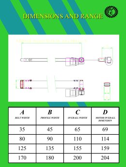
Z/WZKdKZsZd/>
ZEWh^KDEhdE/KE
sZd/>Z/WZKdKZ
ZEWh^ED/EdEE
ITALIANO
ENGLISH
A DESCRIZIONE SIMBOLI
1
A SYMBOL MEANING
1
B DESCRIZIONE APPARECCHIATURA
2
B DESCRIPTION OF THE EQUIPMENT
2
C DATI TECNICI
3
C TECHNICAL DATA
3
D NORME DI SICUREZZA
4
D SAFETY RULES
4
E ESEMPIO DI INSTALLAZIONE
5
E INSTALLATION EXAMPLE
5
F MESSA A PUNTO
5
F SETTING-UP
5
G FUNZIONAMENTO
6
G WORKING
6
H MANUTENZIONE ORDINARIA
8
H ROUTINE MAINTENANCE
8
I INCONVENIENTI E RIMEDI
8
I PROBLEMS AND SOLUTIONS
8
A
DESCRIZIONE SIMBOLI
IN QUESTO MANUALE VENGONO UTILIZZATI
I SEGUENTI SIMBOLI:
A
SYMBOL MEANING
THE FOLLOWING SYMBOL ARE USED IN THIS
MANUAL:
Segnala il rischio di un infortunio It indicates an accident risk or serious
anche mortale o danno grave damage to equipment if this warning
all’apparecchiatura se non viene is not followed
eseguito l’avvertimento
Segnala il rischio di lesioni e It indicates wound and finger
schiacciamenti alle dita per la squashing risk due to movable parts
presenza
di
parti
mobili in the equipment
nell’apparecchiatura
Segnala il divieto di passaggio o Warning to prevent the transit or stop
sosta in un punto che può risultare in hazardous erea because of drive
pericoloso per la presenza di parti in mechanisms
movimento o altro
Segnalano la necesità di utilizzare It is obligatory to wear suitable
particolari accessori come guanti, clothing as gloves, glasses or mask
occhiali e maschere di protezione for operator safety
per la sicurezza dell’operatore
QUESTA APPARECCHIATURA E’ AD
USO
ESCLUSIVAMENTE
PROFESSIONALE.
NON
E’
PREVISTA
PER
UN
UTILIZZO
DIVERSO DA QUELLO DESCRITTO
IN QUESTO MANUALE
WE ADVISE THE USE OF THIS
EQUIPMENT
ONLY
BY
PROFESSIONAL OPERATORS. ONLY
USE THIS MACHINE FOR USAGE
SPECIFICALLY MENTIONED IN THIS
MANUAL
LARIUS – 24032 CALOLZIOCORTE (LECCO) VIA STOPPANI 21 – TEL. 0341/621152 FAX 0341/62143
PAG.1
ITALIANO
B
ENGLISH
B
DESCRIZIONE APPARECCHIATURA
DESCRIPTION OF THE EQUIPMENT
The reciprocator is an element for painting
booths suitable for automatic powder or liquid
paint application. It is made of a supporting
inspectionable structure in steel-sheet integral to
a base with clamps.
The slide guide and the mobile trolley are located
inside the structure. The gun supporting arms are
fixed to the mobile trolley.
The guide and the trolley are made of steel and
aluminium. The trolley runs on bearings.
The motion of the reciprocator is achieved
through a chain in synthetic material mortised on
a gear-motor unit.
A mechanical screw device allows an easy belt
tension.
The motor is asynchronous type, three-phases IP
55 self-breaking. The motorgear is equipped with
a safety adjusting clutch.
The reciprocator’s reversal points necessary to
detect the working range are obtained through an
electronic
potentiometer
allowing
the
adjustments of the reversal points in ranges
variable all along the stroke.
Il reciprocatore è un elemento per le cabine di
verniciatura ed è idoneo all’applicazione in
automatico di vernici in polvere o liquide. E’
costituito
da
una
struttura
portante
ispezionabile in lamiera d’acciaio solidale ad un
basamento dotato di ruote pivottanti e
dispositivi di fissaggio.
All’interno della struttura è posizionata la guida
di scorrimento ed il carrello mobile al quale
sono fissati i bracci di sostegno pistole.
La guida ed il carrello sono realizzati in acciaio
ed alluminio, il carrello scorre sui cuscinetti.
La movimentazione del reciprocatore è ottenuta
mediante gruppo motoriduttore e pulegge
dentate con cinghia in materiale sintetico.
Il motore è di tipo asincrono trifase IP 55
autofrenante. Il riduttore è dotato di frizione di
sicurezza regolabile.
Un dispositivo meccanico a vite consente una
facile tensione della cinghia.
I punti di inversione del reciprocatore necessari
ad individuare il campo di lavoro, sono ottenuti
tramite
un
potenziometro
elettronico,
consentendo la regolazione dei punti di
inversione in campi variabili su tutta la corsa.
1
N°
2
1
3
2
3
5
4
4
5
DESCRIZIONE
DESCRIPTION
Colonna
Column
Braccio pistole
Guns arm
Blocco carrello
Trolley clamping
Carrello
Trolley
Motoriduttore
Gear-motor
LARIUS – 24032 CALOLZIOCORTE (LECCO) VIA STOPPANI 21 – TEL. 0341/621152 FAX 0341/62143
PAG.2
ITALIANO
ENGLISH
Il reciprocatore è completo di una centralina di
comando e controllo in esecuzione a Rack 19”
completa di:
the reciprocator is complete with a Rack 19”
operation control unit complete with :
i
i
i
i
i
i
Start and stop switch
Reversal points switch
Digital indicator of reversal points
i
Potentiometer for speed control
i
i
Power cords
Intercommunication cables
Interruttore di marcia ed arresto
Commutatori per punti di inversione
Indicatore digitale dei punti di inversione
selezionati
Potenziometro per comando a distanza della
velocità
Cavi di alimentazione
Cavi di intercomunicazione
i
i
i
DESCRIZIONE DEL CASSETTO
1.
2.
Interruttore generale
Selettore automaticomanuale
Marcia-arresto
reciprocatore
Selettore
a
chiave
punto alto-basso
Potenziometro
di
regolazione velocità
Visualizzatore di quote
HB 235.09
3.
4.
5.
6.
RACK DESCRIPTION
2
5
1.
2.
1
3.
4.
5.
6 6.
3
Main selector
Automatic-manual
selector
Start-stop selector
Reversal point key
selector
Speed
potentiometer
Digital indicator
HB 235.09
4
Lo strumento elettronico HB 235.09 visualizza la
quota in mm.
The HB 235.09 electronic device shows the
dimension in millimetres.
C
C
DATI TECNICI
TECHNICAL DATA
MODELLO
RNP15
RNP20
RNP25
RNP30
Corsa utile (mm)
1500
2000
2500
3000
Altezza totale (mm)
2350
2850
3350
3850
Total height (mm)
Peso indicativo
230
260
290
320
Approx. Weight
Basamento (mm)
800x550
800x550
800x550
800x550
Basement (mm)
Alimentazione
220 V
220 V
220 V
220 V
Voltage supply
Potenza installata
0,75 Kw
0,75 Kw
0,75 Kw
0,75 Kw
Installed power
PER LE CARATTERISTICHE TECNICHE DI OGNI SINGOLO
COMPONENTE CONSULTARE GLI ALLEGATI
MODEL
working stroke (mm)
CHECK THE ENCLOSED DATAS SHEETS
TECHNICAL DETAILS OF EACH COMPONENTS
LARIUS – 24032 CALOLZIOCORTE (LECCO) VIA STOPPANI 21 – TEL. 0341/621152 FAX 0341/62143
TO
KNOW
PAG.3
ITALIANO
D
ENGLISH
NORME DI SICUREZZA
D
VERIFICARE
L’INTEGRITÀ
ALL’ATTO
DEL
DELL’IMBALLO
RICEVIMENTO.
TOGLIERE
L’APPARECHIATURA DALL’IMBALLO E
CONTROLLARE CHE NON ABBIA SUBITO
DANNI DURANTE IL TRASPORTO
i
NON PERMETTERE CHE PERSONE ESTRANEE
POSSANO ACCEDERE ALL’AREA DI LAVORO
SAFETY RULES
CHECK THAT PAKING IS UNDAMAGED ON
RECEIPT OF THE EQUIPMENT. UNPACK THE
MACHINE AND VERIFY IF THERE HAS BEEN
ANY DAMAGE DURING TRANSPORTATION
i
KEEP THOSE WHO ARE NOT RESPONSABLE FOR THE
EQUIPMENT OUT OF THE WORK AREA
i
PRIMA
DI
SPOSTARE
L’APPARECCHIATURA,
ASSICURARSI CHE I MEZZI DI TRASPORTO E DI
SICUREZZA (CARRO PONTE, TRANS-PALLET, CORDE,
ECC.) SIANO IN GRADO DI SOSTENERE IL PESO
DELL’APPARECCHIATURA STESSA
i
BEFORE MOVING THE UNIT, BE SURE THAT THE
TRANSPORT AND SAFETY MEANS USED (FORK-LIFT,
TRANS-PALLET, ROPES, ETC.) ARE ABLE TO HOLD
THE WEIGHT OF THE UNIT
i
DOPO AVER POSIZIONATO L’APPARECCHIATURA
RICORDARSI DI BLOCCARLA TRAMITE GLI APPOSITI
TIRANTI POSTI SUL CARRELLO
i
AFTER POSITIONNING THE UNIT, REMEMBER TO FIXE IT
WITH THE PROPPER DEVICES LOCATED ON THE
TROLLEY
5
i
i
i
i
SI
RACCOMANDA
DI
COLLEGARE
E
TUTTI
GLI
OGGETTI
L’APPARECCHIATURA
CONDUTTORI VICINI A QUESTA “A TERRA”
FARE ATTENZIONE A NON SCHIACCIARE I CAVI
ELETTRICI DI ALLACCIAMENTO
NON TRAINARE L’APPARECCHIATURA TRAMITE I CAVI
ELETTRICI
PRIMA
DI
OPERARE
QUALSIASI
TIPO
DI
MANUTENZIONE
TOGLIERE
L’ALIMENTAZIONE
ELETTRICA
i
i
i
i
IT IS SUGGESTED TO HEARTH THE EQUIPMENT AND
ALL THE CONDUCTORS OBJECTS NEAR THE WORK
AREA
BE AWARE: DO NOT CRUSH THE ELECTRICAL CABLES
DO NOT PULL THE UNITS USING THE ELECTRICAL
CABLES
BEFORE
ANY
MAINTENANCE
DISCONNECT THE ELECTRIC VOLTAGE
OPERATIONS
QUANDO L’APPARECCHIATURA È IN
FUNZIONE, NON PASSARE O SOSTARE
NEL RAGGIO D’AZIONE DEL BRACCIO
MOBILE
WHEN THE UNIT IS IN OPERATION DO NOT
TRANSIT OR STOP IN THE WORKING AREA
OF THE MOBILE GUNS ARM
QUANDO L’APPARECCHIATURA È IN
AL
FUNZIONE
NON
AVVICINARSI
CARRELLO MOBILE, IN MODO DA
EVITARE
POSSIBILI
LESIONI
O
SCHIACCIAMENTI DELLE DITA
WHEN THE UNIT IS IN OPERATION DO NOT
GET TO CLOSE TO THE MOBILE GUNS ARM,
IN ORDER TO AVOID POSSIBLE INJURIES AT
THE HANDS OR FINGERS
IN CASO DI SMONTAGGIO
PER
MANUTENZIONE
UTILIZZARE ATTREZZATURE
(GUANTI,
APPROPRIATE
MASCHERE,
OCCHIALI,
PER
EVITARE
ECC.)
L’INALAZIONE DI VERNICI IN
POLVERE O IL CONTATTO
CON EVENTUALI PRODOTTI
TOSSICI UTILIZZATI
IN CASE OF DISASSEMBLING
FOR
MAINTENANCE
REASONS, USE THE PROPPER
TOOLS (GLOVES, GLASSES,
ETC.)
TO
AVOID
MASK,
BREATHING POWDER PAINTS
OR GET IN CONTACT WITH
POISON SUBSTANCE USED
LARIUS – 24032 CALOLZIOCORTE (LECCO) VIA STOPPANI 21 – TEL. 0341/621152 FAX 0341/62143
PAG.4
ITALIANO
E
ENGLISH
ESEMPIO DI INSTALLAZIONE
Il reciprocatore è un componente usato nelle
linee di verniciatura automatiche. Come si vede
nell’immagine, due reciprocatori lavorano in
coppia verniciando il pezzo fissato sul
trasportatore. L’operatore si occupa solamente
del ritocco manaule.
E
INSTALLATION EXAMPLE
The reciprocator is a unit used in automatic
painting lines. As shown in the illustration, two
reciprocators are painting simultaneously the
piece fixed on the conveyor, while the operator is
touching up manually
1
5
2
6
3
4
7
8
DESCRIZIONE
1.
2.
3.
4.
5.
6.
7.
8.
F
reciprocatori verticali
cabina di verniciatura
trasportatore a catena
pezzo da verniciare
filtri
box master di gestione apparecchiature
ritocco manuale
alimentatore polveri
MESSA A PUNTO
DESCRIPTION
1.
2.
3.
4.
5.
6.
7.
8.
F
vertical reciprocators
painting booth
chain conveyor
piece to be powder coating
filters
box master control units
manual retouch
powder feeder
SETTING-UP
BLOCCAGGIO DEL RECIPROCATORE
FIXING OF THE RECIPROCATOR
Dopo aver posizionato il reciprocatore nella
posizione voluta, bloccarlo mediante gli appositi
tiranti posti nella parte posteriore del carrello
After having positionned the reciprocator in the
working area, fixe it with the propper devices
located in the rear part of the trolley
POSIZIONAMENTO DEI CAVI ELETTRICI E DEI TUBI DI
ALIMENTAZIONE
POSITIONNING OF ELECTRICAL CABLES AND POWDER
HOSES
LARIUS – 24032 CALOLZIOCORTE (LECCO) VIA STOPPANI 21 – TEL. 0341/621152 FAX 0341/62143
PAG.5
ITALIANO
ENGLISH
Avere cura che i cavi elettrici e i tubi di
alimentazione vernici siano posizionati in modo
da non ostacolare nessun tipo di operazione nei
pressi del reciprocatore, e da non essere
schiacciati o piegati. Avere cura che, in
vicinanza delle pistole, i cavi e i tubi non si
trovino a contatto con le pareti della cabina,
poiché il movimento alternato del braccio
potrebbe tranciarli
Be careful that the electric cables and powder
hoses are positionned in order to work freely
without obstacling the reciprocator when stroking
up and down. Be careful to avoid positionning
powder guns, hoses and cables closed to the
spray booth, as when the support is running up
and down could break them
REGOLAZIONE DEL BRACCIO PORTA PISTOLE
ADJUSTING GUNS SUPPORT
Nel caso la verniciatura comprenda
dei pezzi di diverse dimensioni è
necessario regolare la distanza del
braccio tenendo conto del pezzo di
misure maggiori
In case of mix products powder
coating, it is necessary, when
positionning the support, toconsider
the bigger piece to coat
REGOLAZIONE DELLA CORSA
ADJUSTING THE STROKE
La corsa del braccio è regolabile a piacere,
assicurarsi che il braccio non vada a sbattere
contro la parte inferiore o superiore della cabina
The stroke of the support can be adjusted
according to the required working lenght, watch
out the support of the reciprocator bangs on
lower or top walls of spray booth
G FUNZIONAMENTO
G
i
i
Dare
tensione
al
cassetto
tramite
l’interruttore generale
i Posizionare il selettore automatico-manuale
su “manuale”
i Regolare la velocità tramite il potenziometro
al minimo
i Premere il pulsante “marcia”
i Controllando la corsa girare il selettore su
“basso” quando la pistola si trova nel punto
inferiore del pezzo da verniciare e su “alto”
quando la pistola si trova nel punto
superiore del pezzo da verniciare
i Premere il pulsante “arresto”
i Posizionare il selettore automatico-manuale
su “automatico”
i Premere il pulsante “marcia”
A questo punto il reciprocatore coprirà
solamente la lunghezza del pezzo evitando
quindi che la vernice vada sprecata.
WORKING
Turn the general switch on
i
Put the manual-automatic selector on
“manual”
i Regulate the speed through the potentiometer
at the minimum
i Push the button “marcia”, (running)
i While checking the running, turn the selector
on “basso”, (down) when the gun is in the
lower part of the piece to be painted and on
“alto”, (up) when the gun is in the upper part
of it
i Push the button “arresto”, (stop)
i Put the manual-automatic selector on
“automatic”
i Push the button “marcia”, (running)
At this point the reciprocator will cover only the
length of the piece you are painting avoiding to
waste paint.
LARIUS – 24032 CALOLZIOCORTE (LECCO) VIA STOPPANI 21 – TEL. 0341/621152 FAX 0341/62143
PAG.6
ITALIANO
ENGLISH
ATTENZIONE: nel caso in cui, a tensione
disinserita,
il
braccio
venga
spostato
manualmente, la quota memorizzata viene persa
col possibile rischio che, una volta riattivato il
reciprocatore, la slitta vada a sbattere nel punto
superiore o nel punto inferiore della struttura. In
questo caso:
i Dare
tensione
al
cassetto
tramite
l’interruttore generale.
i Posizionare il selettore automatico-manuale
su “manuale”.
i Regolare la velocità tramite il potenziometro
al minimo.
i In corrispondenza del punto inferiore di
inversione, premere il pulsante azzeramento
sullo strumento QEM HB 235.09. (foto 1)
A QUESTO PUNTO RIPETERE LA PROCEDURA
“FUNZIONAMENTO”
ATTENTION: at no voltage, should the actuating
arm be manually moved, the instruction given are
no more considered and it can happen that when
you start working again the arm beat against the
upper and lower point of the installation. In this
case:
IL MOTORIDUTTORE È DOTATO DI UNA FRIZIONE DI
SICUREZZA REGOLABILE A PIACERE (foto 2). IN QUESTO
MODO, IN CASO DI ERRATA REGOLAZIONE DELLA CORSA
E DI URTO TRA IL BRACCIO E LA CABINA, IL MOTORE
GIRERÀ A VUOTO SALVAGUARDANDO L’INTEGRITÀ DELLA
CINGHIA. LA FRIZIONE VA REGOLATA IN BASE AL PESO
POSTO SUL BRACCIO
IL MOTORE E’ DI TIPO AUTOFRENANTE PER GARANTIRE
CHE IL PESO DELLE PISTOLE, AD APPARECCHIATURA
FERMA, NON SPOSTI IL BRACCIO VERSO IL BASSO. IN
CASO SI DEBBA SPOSTARE IL BRACCIO MANUALMENTE È
NECESSARIO AZIONARE L’APPOSITA LEVA POSTA SULLA
PARTE POSTERIORE DEL MOTORE (foto 3), E,
TENENDOLA TIRATA SPOSTARE MANUALMENTE IL
BRACCIO
THE MOTORGEAR IS EQUIPPED WITH A SAFETY CLUTCH
ADJUSTABLE (PICTURE 2), IN THIS WAY, IN CASE OF
MISTAKE IN ADJUSTING THE STROKE AND BANG BETWEEN
THE SUPPORT AND THE BOOTH, THE MOTOR IS RUNNING
FREE IN ORDER TO AVOID DAMAGE TO THE BELT. THE
CLUTCH HAS TO BE ADJUSTED ACCORDING TO THE
WEIGTH POSITIONNED ON THE SUPPORT
THE ELECTRIC MOTOR IS SELF-BREAKING TO KEEP THE
WORKING STROKE SIZES SET UP. IN CASE OF MANUAL
MOVING THE SUPPORT, IT IS NECESSARY TO USE THE
PROPPER LEVER POSITIONNED OF THE REAR PART OF THE
MOTOR (PICTURE 3). KEEPING IT PULLED, MOVE
MANUALLY THE SUPPORT
i
Turn the general switch on.
i
Put the manual-automatic selector on
“manual”.
Regulate the speed through the potentiometer
at the minimum.
In correspondence with the lower point of the
inversion, push the button to zero setting of
the instrument QEMHB 235.09.
AT THIS POINT JUST REPEAT THE “WORKING”
i
i
OPERATIONS
ATTENZIONE
WARNING
L’OPERAZIONE SOPRA DESCRITTA È
CONSENTITA
SOLAMENTE
PER
MANUTENZIONE
E
A
IMPIANTO
DISINSERITO
THE ABOVE MENTIONED OPERATION IS
ALLOWED ONLY IN CASE OF MAINTENANCE
AND WITH THE PLANT OFF
IL TIRAGGIO DELLA CINGHIA È REALIZZATO TRAMITE DUE
VITI POSTE SULLA TESTATA DI RINVIO DELLA GUIDA
LINEARE (foto 4). È IMPORTANTE FARE IN MODO CHE LE
VITI SIANO TIRATE NELLA STESSA MISURA (CONTANDO IL
NUMERO DI GIRI) IN MODO CHE LA CINGHIA NON SIA
INCLINATA
THE TENSION OF THE BELT IS MADE BY TWO SCREWS
POSITIONNED GUIDE HEAD (PICTURE 4). IT IS VERY
IMPORTANTS THAT THE SCREWS ARE EQUALLY
TIGHTENED (COUNTING THE NUMBER OF TURNS) IN ORDER
THAT THE BELT IS NOT INCLINED
LARIUS – 24032 CALOLZIOCORTE (LECCO) VIA STOPPANI 21 – TEL. 0341/621152 FAX 0341/62143
PAG.7
ITALIANO
ENGLISH
Frizione
Clutch
Foto 2
Picture 2
Pulsante di
azzeramento
Foto 1
Picture 1
Girare in senso orario Turn clockwise to tight
per stringere la frizione
the clutch
Button to zero
setting
Girare in senso antiorario Turn counter clockwise
per allentare la frizione
to loose the clutch
Leva per sbloccaggio freno motore
Viti per tiraggio cinghia
Lever to release motor brake
Screw for belt tightening
Foto 3
Picture 3
Foto 4
Picture 4
ALIMENTAZIONI E COLLEGAMENTI
1.
2.
3.
4.
Alimentazione proximity
ed encoder
Comando basculamento
pistole (opzione)
Alimentazione motore
Alimentazione da linea
(220V)
FEEDING AND CONNECTIONS
1.
1
2.
3.
4.
2
H
i
i
MANUTENZIONE ORDINARIA
Controllare periodicamente il tiraggio della
cinghia
Ogni mese ingrassare le ruote del carrello
tramite gli appositi ingrassatori
3
H
Proximity and encoder
feeding
Gun oscillation
(optional)
Motor feeding
Power feeding (220V)
4
ROUTINE MAINTENANCE
i
Check periodically the tension of the belt
i
Every month grease the trolley wheels
through the greasers located on the trolley
LARIUS – 24032 CALOLZIOCORTE (LECCO) VIA STOPPANI 21 – TEL. 0341/621152 FAX 0341/62143
PAG.8
ITALIANO
I
i
ENGLISH
INCONVENIENTI E RIMEDI
Î
Î
Verificare la correttezza degli allacciamenti
Verificare la funzionalità degli apparati interni
al cassetto (solo personale qualificato)
Î Verificare che il cavo di alimentazione sia
i Il motore non funziona
collegato
Î Verificare la tensione di uscita a vuoto
dell’inverter (solo personale qualificato)
Î Verificare che la cinghia non sia rotta
i Il braccio porta pistole non si muove
Î Verificare il tiraggio della frizione come
descritto a pag. 6
Î Verificare che i proximity rilevino il passaggio
i Nella modalità “MANUALE” non avviene
del carrello
l’inversione del moto
Î Verificare la funzionalità dei proximity
Î Verificare il serraggio dell’encoder montato
i Nella modalità “AUTOMATICO” il braccio
sull’albero di trasmissione
porta pistole non mantiene le quote
Î Verificare la funzionalità dell’encoder
impostate
NEL CASO DI COLLISIONE È POSSIBILE CHE, RIAVVIANDO IL RECIPROCATORE, QUESTO NON PARTA. L’INVERTER,
INFATTI, VA IN ALLARME E IMPIEGA QUALCHE MINUTO PER RESETTARSI. IN QUESTI CASI È SUFFICIENTE SPEGNERE
L’APPARECCHIATURA E RIACCENDERLA DOPO 5-10 MINUTI.
I
Il cassetto di gestione non funziona
PROBLEMS AND SOLUTIONS
i
The control box doesn’t work
Î
Î
i
The motor doesn’t work
Î
Î
i
The guns holding arm doesn’t move
Î
Î
i
No inversion of the movement in “manual”
mode
Î
Î
i
In “automatic “ mode the guns holding arm
does not keep the set measures
Î
Î
Check if the cables are properly connected
Control the interlockings functioning inside
the rack (only by skilled technicians)
Check if the elettricity supply cable is
properly connected
Control the outlet no-load voltage of the
inverter (only by skilled technicians)
Check any possible breakage of the driving
belt
Control the clutch adjustment as shown at
page 6
Check if the proximity pick ups read the
saddle approaching
Control the proximity pick ups functioning
Control the tightening of the encoder fitted on
the trasmission shaft
Control the encoder functioning
LARIUS – 24032 CALOLZIOCORTE (LECCO) VIA STOPPANI 21 – TEL. 0341/621152 FAX 0341/62143
PAG.9
ITALIANO
ENGLISH
IN CASE OF IMPACTS, THE RECIPROCATOR MAY NOT OPERATE AT THE RESTART. INFACT THE INVERTER WILL BE IN
ALARM MODE AND IT WILL TAKE A FEW MINUTES TO RE-SET. IT WILL BE ENOUGH TO SWITCH OFF THE EQUIPMENT AND
RESTART IT AFTER 5-10 MINUTES
LARIUS – 24032 CALOLZIOCORTE (LECCO) VIA STOPPANI 21 – TEL. 0341/621152 FAX 0341/62143
PAG.10
RECIPROCATORE - PARTICOLARI GUIDA LINEARE E MANUTENZIONE
RECIRPOCATOR - LINEAR GUIDE SPARE PARTS
RICAMBI CARRELLO MOBILE - MOBILE CART SPARE PARTS
RICAMBI TESTATA MOTRICE (INFERIORE) - DRIVING HEAD (LOWER) SPARE PARTS
RICAMBI TESTATA REGISTRAZIONE (SUPERIORE) - ADJUSTING HEAD SPARE PARTS (UPPER)
MANUTENZIONE GENERALE
Premessa:
Descrizione e Caratteristiche Tecniche Unita’ Lineari LITEK a Cinghia Dentata.
Le Unita’ Lineari sono state concepite per essere semplici e funzionali per il montaggio, per la
manutenzione e per la sostituzione delle parti usurabili, dovute al ciclo di lavoro nel tempo.
Le unita’ lineari assolvono il compito di movimentare alternativamente (avanti ed indietro) organi,
gruppi e quant’altro richiesto a fini industriali.
Le Unita’ a Cinghia Dentata sono composte dai seguenti Gruppi:
-Testata Motrice -Testata Rinvio -Profilato Strutturale -Carrello -Trasmissione Interna del Moto
-Motorizzazione Esterna
Le Unita’ a Cinghia Dentata non possono garantire un’alta precisione di traslazione e di ripetibilita’,
che si aggira in ogni modo su bassi valori di 0,1-0,2 mm. Cio’ dipende dalle reali tolleranze sul passo
dei denti delle cinghie per i limiti della vulcanizzazione della gomma.
Con la trasmissione a cinghia dentata come contropartita si ottiene alte velocità di traslazione e
d’accelerazione, con basse inerzie e bassi attriti.
Uso e manutenzione
Controllo Manomissioni
Le viti ed i dadi posti nei punti di registrazione sono marcati con vernice, in tal modo si evidenziano
immediamente le manomissioni.
Sono manomissioni anche, crash per motori in fuga, impatti da corpi esterni, introduzione di materiali
vari, utilizzi non previsti, assenza di controllo e manutenzione
Garanzia – Norme Le Unita’ Lineari sono garantite da difetti di costruzione e sottoposte a collaudo
ispettivo. Nel caso le unità necessitassero d’interventi di manutenzione , dovuti ad un normale logorio
lavorativo , il cliente è tenuto a leggere le Istruzioni prima di procedere.
Si declinano responsabilità per eventuali errori, manomissioni o danni causati nell’utilizzo, e se le
nostre raccomandazioni o procedure non sono applicate.
Controlli da Eseguire (RIFERIRSI A DISEGNO ESPLOSO “TESTATA DI REGISTRAZIONE”)
Il controllo visivo e tattile e’ molto importante ai fini del buon funzionamento e della durata nel tempo
delle unita’.
- Il primo controllo e’ verificare se la cinghia di trasmissione e’ tesa al giusto valore del 2 %, e gira
perfettamente in centro all’unità.
Come centratura procedere attraverso una delle due viti centrali sulla testata di rinvio (quell’opposta
al motore) parte frontale rotando d’alcuni gradi in un senso o nell’altro e controllare la cinghia in
movimento come si sposta, ottenuto lo spostamento nella direzione giusta, insistere passo passo
sempre con l’unità in movimento fino a raggiungere la posizione voluta.
Tensionamento della cinghia, ciclicamente (almeno ogni anno) ad unità ferma esercitare una
pressione di 5 / 6 kg sulla cinghia al centro del modulo con il carrello spostato ad un’estremità, senza
toccare il profilato, diversamente, tramite le due viti sopra descritte agire in senso antiorario fino a che
la cinghia in orizzontale non sfiori il profilato sottostante, quindi agire su entrambe in modo uniforme
in senso orario compiendo 2 giri per vite ogni metro di lunghezza dell’unità, tensione ottima per uno
spostamento del carrello costante, senza sovraccaricare i cuscinetti posti nelle 2 pulegge alloggiate
nelle testate, garantendo una ripetitivita’ nel posizionamento, che altrimenti non sarebbe possibile.
- Il secondo controllo e’ la verifica delle rotelle del carrello.
Se tutte le rotelle ruotano alla medesima velocità , vuol dire che hanno tutte il medesimo precarico e
solo in questo caso i carichi applicati sul carrello sono distribuiti equamente su ogni rotella . Se invece
ruotano solo alcune rotelle, queste sono caricate con un valore superiore a quello che dovrebbero
avere, mentre quelle che strisciano non sopportano alcun carico ma usurano sia la pista di contatto
che la barra di scorrimento, In definitiva tutto cio’ accorcia la durata delle rotelle, maggiori errori
geometrici durante il movimento e decadenza anticipata della durata delle piste e dei corpi volventi
che le compongono.
L’unita’ necessita subito di manutenzione per non compromettere definitivamente le barre di
scorrimento.
Registrazione o Sostituzione Rotelle (vedere disegno esploso “CARRELLO MOBILE”)
Le rotelle si possono suddividere in 2 tipologie: -Fisse - Registrabili ( ambedue con calotta di
protezione).
Le Rotelle Fisse sono il punto di riferimento del carrello rispetto al profilato, e non sono interessate
alla registrazione perché sono montate in fori calibrati.
Le Rotelle Registrabili sono quelle che danno rigidita’ al sistema di contrasto alle coppie di
ribaltamento che gravano sul carrello, dovute ai carichi risultanti applicati (vedi valori dichiarati nei
cataloghi tecnici ). Le Rotelle Registrabili per l’importanza che rivestono devono essere avvicinate
alla barra di scorrimento con estrema accuratezza, quest’avvicinamento e’ ottenuto tramite vite di
pressione che agisce sul gambo del perno, con dadi allentati quel tanto che basta affinché si possano
muovere.
Per intervenire sulle rotelle occorre smontare le Calotte di Protezione, svitando le 2 viti che le fissano,
lato del carro con vista sede grani di registro, sulla piastra carro al centro della calotta, tolte le
calotte, le rotelle sono a vista, provare con due dita a farle girare, senza che il carro si muova, se ciò
avviene significa che sono scariche, provvedere al precarico agendo in questo modo, allentare
leggermente il dado che fissa le rotelle senza creare gioco, quindi agire in senso orario sui grani di
registro piano piano su entrambe le rotelle, fina a costatare nel girarle con le dita un aumento d’attrito
sulle barre di scorrimento con il carro bloccato da una testata, è indispensabile che la resistenza sia
uguale in entrambe le rotelle e che non ci sia gioco sui perni, a questo punto ruotare ancora in senso
orario i due grani di 20°, poi bloccare i dadi dei perni com’erano in precedenza.
Per la sostituzione delle rotelle, prima bloccare quelle fisse, poi procedere con le registrabili come
sopra indicato.
Ricordiamo che le calotte di protezione servono anche a pulire le barre di scorrimento, mantenere
una certa quantità di grasso nelle sedi dei due feltrini laterali attraverso l’estrazione dei due grani sul
dorso della calotta.
Ricordiamo che i grani fungono da registro molla per pressione feltro.
Sostituzione cinghia.
Allentare completamente la cinghia con la procedura descritta nel tensionamento, togliere
completamente i due morsetti fissati frontalmente alle estremità del carro, sfilare la cinghia con
l’avvertenza di legare ad un’estremità uno spago abbastanza lungo da permettere di facilitare
l’inserimento della nuova cinghia, prima però assicurarsi che la lunghezza sia uguale alla sostituita,
eventualmente tagliare la parte eccedente con forbici da lamiera o con una taglierina, controllare che
nell’inserimento la cinghia non si attorcigli e che sia rivolta con i denti verso il centro del modulo,
inserirla nei morsetti com’era posta la vecchia, bloccare i morsetti sul carro poi procedere al
tensionamento come descritto nell’apposito capitolo, è estremamente importante controllare la
centratura con l’unità in movimento.
GENERAL MAINTENANCE
Description and Technical Units' Linear LITEK timing belt. The Unit 'Linear are designed to
be simple and functional for the installation, maintenance and replacement of wear parts,
due to duty cycle over time. The units' linear fulfill the task of alternately moving (forward
and backward) organs, groups, and anything else required for industrial purposes. Units'
are composed of toothed belt following groups:-Head Tractor Head-Referral-structural
profile-Cart-Transmission of Internal Engine External Moto-Unit 'toothed belt cannot
ensure high accuracy and repeatability of travel' , which is around in every way on low
values ..of 0.1-0.2 mm. This' tolerance depends on the actual pitch of the teeth of the belts
to the limits of the vulcanization of rubber. With toothed belt drive in return you get highspeed travel and high acceleration with low inertia and low friction.
USE AND MAINTENANCE
Control Tampering
The screws and bolts at the registration points are marked with paint, this will show you
immediately tampering. They are also tampering, crash engine in flight, impacts from
external bodies, introduction of various materials, not provided for use, lack of control and
Maintenance Guarantee The Standards Unit 'Linear are guaranteed against manufacturing
defects and are subject to acceptance inspection. If the units make up for maintenance
due to normal wear business, the customer must read the instructions before proceeding.
We accept no responsibility for any errors, tampering or damage caused usage, and if our
recommendations or procedures are not applied.
INSPECTION (REFER TO EXPLODED "ADJUSTING heads")
The visual and tactile and 'very important for the smooth operation and durability of the
units'. - The first check 'to check if the transmission belt' aimed at the right value of 2%,
and runs perfectly in the center of the unit. How to proceed through a centering of the two
center screws on the head of reference by rotating the front of a few degrees one way or
another, and check the belt in motion as you move, obtaining the move in the right
direction, step by step, always insist on the move with the drive until you reach the desired
position.
BELT TENSION – PERIODICALLY
(at least annually) to units still exert a pressure of 5 / 6 kg on the belt at the center of the
module with the truck moved at one end, without touching the profile, in contrast, using the
two screws above act counterclockwise until the belt does not just reach the horizontal
section below, then act on both uniformly clockwise 2 turns for making lives every meter of
length of the unit, excellent power for a constant movement of the trolley, without
overloading 2 seats in the pulley bearings housed in the head, giving a repetition
'positioning, which otherwise would not be possible.
- The second check, consisting in checking the wheels of the truck. If all wheels rotate at
the same speed, which means they have all the same pre-load and only in this case the
applied loads on the truck are equally distributed on each wheel. If, however, only a few
wheels rotate, they are loaded with a value greater than what they should have, while
those that move but do not bear any load is the wear track contact that the scroll bar, and
anything else 'shortens the duration of Accessibility, more geometric errors during
movement and decay of the early life of the tracks and rolling elements that compose
them. The units' maintenance needs immediately to affect definitely not the scroll bars.
Registration or Replacement Wheels
(see exploded "MOBILE CART") The wheels can be divided into two types: Fixed-Recordable (both with protective cover). The fixed wheels are the reference point of the
truck compared to the profile, and are not interested in registration because they are
mounted in holes. The Rollers recorded are those that give rigidity 'of the system couples
to contrast reversal which affect the shopping cart, due to the loads resulting applied (see
values ..reported in the technical catalogs). Adjustable wheels for the importance to be
approached with extreme accuracy the scroll bar, and this approach is obtained by
pressure acting on the shank of the pin, with loose nuts just enough to move them
To work on wheels, take off the protective cover, unscrew the 2 screws that secure the
side of the wagon seat with a view of setting screws on the plate at the center of the tank
shell, removed the caps, the wheels are exposed, try two fingers to make them turn
without moving the wagon, if it does mean that they are run to provide the preload acting in
this way, loosen the nut securing the wheels without causing the game, so act in a
clockwise direction on the grain floor register plan on both wheels, to note in fine turn them
with your fingers to increase friction on the scroll bar with a header blocked by the cart, it is
essential that the resistance is equal in both wheels and that there is no play on the pins At
this point still rotate clockwise the two grains of 20 degrees, then tighten the nuts of the
pins as they were before. To replace the wheels, block those fixed first, then proceed with
the recordings as indicated above.
Remember that the protective covers also serve to clean the scroll bars to maintain a
certain amount of fat in the premises of the two side pads through the extraction of the two
grains on the back of the shell. Recall that the grains act as a spring adjustment to
pressure felt.
Belt replacement
Loosen the belt tension with the procedure described in, drain out the two terminals
attached to the front end of the tank, remove the belt with the warning at one end to tie a
rope long enough to allow insertion of the new belt , but first make sure that length is equal
to be replaced, possibly cut off the excess with scissors or a cutter plate, check that
inserting the belt is not twisted and turned with the teeth toward the center of the form,
insert it was placed in the old terminals, block terminals on the cart and then proceed to
the tension as described in the chapter, it is extremely important to check the centering
with the moving unit.
COSTRUTTORE / MANUFACTURER:
23801 CALOLZIOCORTE – LECCO – ITALY – Via Stoppani, 21
tel. (39) 0341/62.11.52 – fax. (39) 0341/62.12.43
e-mail: [email protected] - internet: www.larius.com
La casa produttrice si riserva la possibilità di variare caratteristiche e dati del presente
manuale in qualunque momento e senza preavviso
Due to a constant product improvement, the factory reserves the right to modify technical
details mentioned in this manual without prior notice
Scarica