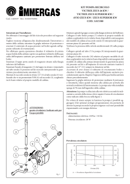
KIT RICIRCOLO CALDAIE SERIE
HERCULES KW E HERCULES CONDENSING KW
COD. 3.020001
Cod. 1.028071 - Rev. ST.001057/000
IL PRESENTE FOGLIO È DA LASCIARE
ALL'UTENTE ABBINATO AL
LIBRETTO ISTRUZIONI DELLA
CALDAIA
AVVERTENZE GENERALI.
Tutti i prodotti Immergas sono protetti con idoneo imballaggio da trasporto. Il materiale deve essere immagazzinato in ambienti asciutti ed al riparo dalle intemperie. Il
presente foglio istruzioni contiene informazioni tecniche
relative all’installazione del kit Immergas. Per quanto
concerne le altre tematiche correlate all’installazione del
kit stesso (a titolo esemplificativo: sicurezza sui luoghi di
lavoro, salvaguardia dell’ambiente, prevenzioni degli infortuni), è necessario rispettare i dettami della normativa
vigente ed i principi della buona tecnica.
L’installazione o il montaggio improprio dell’apparecchio
e/o dei componenti, accessori, kit e dispositivi Immergas
potrebbe dare luogo a problematiche non prevedibili a
priori nei confronti di persone, animali, cose. Leggere
attentamente le istruzioni a corredo del prodotto per
una corretta installazione dello stesso.
L'installazione e la manutenzione devono essere effettuate in ottemperanza alle normative vigenti, secondo le
istruzioni del costruttore e da parte di personale abilitato
nonché professionalmente qualificato, intendendo per
tale quello avente specifica competenza tecnica nel settore
degli impianti, come previsto dalla Legge.
INSTALLAZIONE MODELLI HERCULES KW E
HERCULES CONDENSING KW (FIG. 1).
Togliere tensione all'apparecchio disalimentando
l'interruttore a monte della caldaia.
Smontare la mantellatura della caldaia.
Accertarsi che il rubinetto ingresso acqua fredda (12)
sia chiuso e scaricare parzialmente il contenuto del bollitore agendo sull’apposito rubinetto di svuotamento.
Per effettuare questa operazione aprire un qualsiasi
rubinetto dell’acqua calda dell’impianto sanitario
per permettere l’entrata dell’aria nel boiler. Asportare
momentaneamente la coibentazione superiore (1) ed
Composizione kit:
n° 2- Guarnizioni 24x16x2 mm (2)
n° 1- Tubo allacciamento ricircolo (3)
n° 2- Guarnizioni 29x20x2 mm (4)
n° 1- Circolatore (5)
n° 2- Curve circolatore (da scegliere in funzione del proprio
modello di caldaia (6)
n° 1- Valvola unidirezionale OV20 (7)
n° 1- Guarnizione 34x27x2 mm (8)
n° 1 - Dado ribassato (9)
n° 1- Tubo allacciamento (10)
n° 1- Raccordo tubo allacciamento 3/4'' (10)
n°2 - Guarnizioni 18x10x2 (13)
n° 1- Tubo con valvola di
non ritorno OV 15 (14)
Legenda:
1 - Coibentazione bollitore
12 - Rubinetto entrata
acqua fredda
15 - Tubo presente in
caldaia
1
N.B.: prestare attenzione al collegamento della pompa
che deve avere il senso di circolazione dell'acqua uguale
alla freccia rappresentata in figura.
Ultimato il montaggio coprire gli allacciamenti del
bollitore con la coibentazione (1) precedentemente
asportata.
Allacciare il circolatore ad una rete di 230V ±10% /
50Hz rispettando la polarità L-N ed il collegamento
di terra, su tale rete deve essere prevista una disconnessione onnipolare con categoria di sovratensione
di classe III.
Accertarsi di aver chiuso il rubinetto di svuotamento
boiler e chiudere il rubinetto dell’acqua calda dell’impianto sanitario precedentemente aperto. Riaprire
il rubinetto entrata acqua fredda (12), rimontare la
mantellatura, quindi ridare tensione alla caldaia per
portarla alle normali condizioni di funzionamento.
Fig. 1
7
8
9
2
10
11
6
4
5
2
eliminare il tappo presente sul bollitore.
Effettuare il collegamento del kit come rappresentato
in figura.
4
ATTENZIONE:
questo circolatore è indicato solo per
l'acqua potabile
3
12
N.B.: prestare attenzione al collegamento della
pompa che deve avere il senso di circolazione
dell'acqua uguale alla freccia rappresentata in
figura.
calda dell’impianto sanitario precedentemente
aperto. Riaprire il rubinetto entrata acqua fredda
(12), rimontare la mantellatura, quindi ridare
tensione alla caldaia per portarla alle normali
condizioni di funzionamento.
DATI TECNICI:
-Alimentazione elettrica: .......230 Vac / 50 HZ
-Potenza: .................................................... 55 W
-Assorbimento: ........................................0,24 A
Prevalenza circolatore
C
B
Prevalenza (m c.a.)
Togliere tensione all'apparecchio disalimentando
l'interruttore a monte della caldaia.
Smontare la mantellatura della caldaia.
Accertarsi che il rubinetto ingresso acqua fredda
(12) sia chiuso e scaricare parzialmente il contenuto del bollitore agendo sull’apposito rubinetto
di svuotamento.
Per effettuare questa operazione aprire un qualsiasi rubinetto dell’acqua calda dell’impianto
sanitario per permettere l’entrata dell’aria nel
boiler. Asportare momentaneamente la coibentazione superiore (1) ed eliminare il tappo presente
sul bollitore.
Eliminare il tappo presente sul tubo (3).
Effettuare il collegamento del kit come rappresentato in figura.
Ultimato il montaggio coprire gli allacciamenti
del bollitore con la coibentazione (1) precedentemente asportata.
Allacciare il circolatore ad una rete di 230V ±10%
/ 50Hz rispettando la polarità L-N ed il collegamento di terra, su tale rete deve essere prevista
una disconnessione onnipolare con categoria di
sovratensione di classe III.
Accertarsi di aver chiuso il rubinetto di svuotamento boiler e chiudere il rubinetto dell’acqua
Prevalenza (kPa)
INSTALLAZIONE MODELLO
HERCULES SOLAR 200
CONDENSING (FIG. 2).
A
A = Prevalenza disponibile al
circolatore terza velocità
B = Prevalenza disponibile
al circolatore seconda
velocità
C = Prevalenza disponibile al
circolatore prima velocità
Portata (l/h)
Composizione kit:
n° 2- Guarnizioni 24x16x2 mm (2)
n° 1- Tubo allacciamento ricircolo (3)
n° 2- Guarnizioni 29x20x2 mm (4)
n° 1- Circolatore (5)
n° 2- Curve circolatore (da scegliere in funzione del proprio
modello di caldaia (6)
n° 1- Valvola unidirezionale OV20 (7)
n° 1- Guarnizione 34x27x2 mm (8)
n° 1 - Dado ribassato (9)
n° 1- Tubo allacciamento (10)
n° 1- Raccordo tubo allacciamento 3/4'' (11)
n°2 - Guarnizioni 18x10x2 (13)
n° 1- Tubo con valvola di non ritorno OV 15 (14)
15
7
2
13
14
1
8
9
2
10 11
6
4
5
13
Legenda:
1 - Coibentazione bollitore
12 - Rubinetto entrata
acqua fredda
15 - Tubo presente in
caldaia
Fig. 2
4
ATTENZIONE:
questo circolatore è indicato solo per
l'acqua potabile
3
12
BOILER RECIRCULATION KIT SERIES
HERCULES KW AND HERCULES CONDENSING KW
CODE 3.020001
Code 1.028071 - Rev. ST.001057/000
THIS SHEET MUST BE LEFT WITH THE
USER ALONG WITH THE BOILER
INSTRUCTION BOOK
GENERAL WARNINGS.
All products are protected with suitable transport packaging.
The material must be stored in dry environments and
protected against weathering.
This instruction manual provides technical information
for installing the kit. As for the other issues related to
kit installation (e.g. safety in the work site, environment
protection, injury prevention), it is necessary to comply
with the provisions specified in the regulations in force
and principles of good practice.
Improper installation or assembly of the appliance and/
or components, accessories, kit and devices can cause
unexpected problems to people, animals and objects.
Read the instructions provided with the product carefully to ensure a proper installation.
Installation and maintenance must be performed in
compliance with the regulations in force, according
to the manufacturer's instructions and by authorised
professionally qualified staff, intending staff with specific technical skills in the plant sector, as envisioned
by the Law.
INSTALLATION OF HERCULES KW AND
HERCULES CONDENSING KW MODELS (FIG.
1).
Remove voltage from the appliance by disconnecting
the switch upstream from the boiler.
Re-mount the boiler casing.
Make sure that the cold water inlet tap (12) is closed
and partially drain the contents of the storage tank
acting on the relevant drain valve.
To perform this operation open any hot water tap of
the domestic hot water system to let air into the storage
tank. Temporarily remove the upper insulation (1) and
the cap on the storage tank.
Connect the kit as shown in the figure.
Kit composition:
n° 2- Gaskets 24x16x2 mm (2)
n° 1- Recirculation connection pipe (3)
n° 2- Gaskets 29x20x2 mm (4)
n° 1- Circulator (5)
n° 2- Circulator curves (to be chosen according to your
boiler model (6)
n° 1- One-way valve OV20 (7)
n° 1- Gaskets 34x27x2 mm (8)
n° 1 - Lowered nut (9)
n° 1- Connection pipe (10)
n° 1- Connection pipe fitting 3/4'' (10)
n° 2- Gaskets 18x10x2 (13)
n° 1- Pipe with non-return valve OV 15 (14)
Key:
1 - Storage tank insulation
12 - Cold water inlet cock
15 - Pipe present in boiler
Fig. 1
7
1
8
9
2
10
11
6
4
5
2
N.B.: pay attention to the connection of the pump
whose water circulation direction must be the same
as the arrow shown in the figure.
Once assembly is complete, cover the storage tank connections with the previously removed insulation (1).
The power supply cable must be connected to a 230V
±10% / 50Hz mains supply observing L-N polarity
and earth connection; this network must also feature
an omnipolar circuit breaker of class III over-voltage
category.
Make sure you have closed the cylinder drain valve and
close the domestic hot water system valve which was
opened previously. Reopen the cold water inlet valve
(12), remount the casing, then power the boiler to bring
it to normal operating conditions.
4
ATTENTION:
this circulator is indicated for drinking
water only
3
12
N.B.: pay attention to the connection of the
pump whose water circulation direction must
be the same as the arrow shown in the figure.
Once assembly is complete, cover the storage
tank connections with the previously removed
insulation (1).
The power supply cable must be connected to a
230V ±10% / 50Hz mains supply observing L-N
TECHNICAL DATA:
-Electric power supply: ..........230 Vac / 50 HZ
-Power: ....................................................... 55 W
-Absorption: .............................................0.24 A
Circulator head.
C
B
Head (m c.a.)
Remove voltage from the appliance by disconnecting the switch upstream from the boiler.
Re-mount the boiler casing.
Make sure that the cold water inlet tap (12) is
closed and partially drain the contents of the
storage tank acting on the relevant drain valve.
To perform this operation open any hot water tap
of the domestic hot water system to let air into
the storage tank. Temporarily remove the upper
insulation (1) and the cap on the storage tank.
Remove the cap from the pipe (3).
Connect the kit as shown in the figure.
polarity and earth connection; this network must
also feature an omnipolar circuit breaker of class
III over-voltage category.
Make sure you have closed the cylinder drain
valve and close the domestic hot water system
valve which was opened previously. Reopen the
cold water inlet valve (12), remount the casing,
then power the boiler to bring it to normal operating conditions.
Head (kPa)
INSTALLATION OF HERCULES
SOLAR 200 CONDENSING MODEL
(FIG. 2).
A
A = Head available to the
third speed circulator
B = Head available to the
second speed circulator
C = Head available to the first
speed circulator
Flow rate (l/h)
Kit composition:
n° 2- Gaskets 24x16x2 mm (2)
n° 1- Recirculation connection pipe (3)
n° 2- Gaskets 29x20x2 mm (4)
n° 1- Circulator (5)
n° 2- Circulator curves (to be chosen according to your
boiler model (6)
n° 1- One-way valve OV20 (7)
n° 1- Gaskets 34x27x2 mm (8)
n° 1 - Lowered nut (9)
n° 1- Connection pipe (10)
n° 1- Connection pipe fitting 3/4'' (11)
n° 2- Gaskets 18x10x2 (13)
n° 1- Pipe with non-return valve OV 15 (14)
15
7
2
13
14
1
8
9
2
10 11
6
4
5
13
Key:
1 - Storage tank insulation
12 - Cold water inlet cock
15 - Pipe present in boiler
Fig. 2
4
ATTENTION:
this circulator is indicated for drinking
water only
3
12
Scaricare