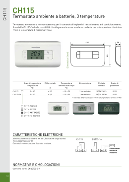
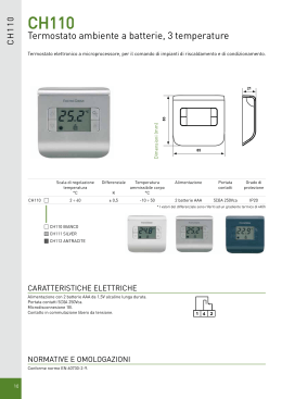
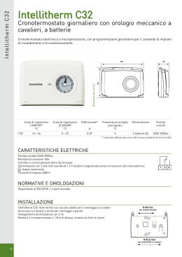
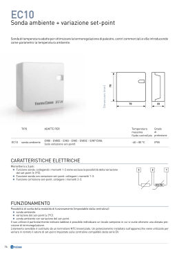
Regulation
Regolazione
EASY CLIMA SA 230
VERSION
1.6
TECHNICAL/INSTALLATION MANUAL
MANUALE TECNICO/INSTALLAZIONE
SAFETY WARNINGS - AVVERTENZE PER LA SICUREZZA
Read this manual carefully before installing and/or using the
equipment and keep it in an accessible place.
This equipment constitutes a component which is part of
complex installations: it is the responsibility of the electrical
installer to draw up the general diagram of the system and
the electrical connections outside the equipment.
The manufacturer’s technical office can be contacted on the
numbers shown on the back of this manual for queries or
special technical requests.
Le g g e re co n at te n z i o n e q u e s to l i b re t to p r i m a
dell’installazione e/o dell’uso dell’apparecchiatura e
conservarlo in un luogo accessibile.
La presente apparecchiatura costituisce un componente che
fa parte di installazioni complesse: è compito dell’impiantista
elettrico redigere lo schema generale dell’impianto e dei
collegamenti elettrici esterni all’apparecchiatura.
L’ufficio tecnico del Costruttore si rende disponibile
ai numeri indicati sul retro del presente libretto per
consulenze o richieste tecniche particolari.
•
CAUTION
Installation and maintenance must only be carried out by
qualified personnel.
The hydraulic and electrical systems and the places where
the equipment is to be installed must comply with the
safety, accident prevention and fire prevention standards
in force in the country of use.
•
ATTENZIONE
L’installazione e la manutenzione vanno eseguiti solo da
personale qualificato.
Gli impianti idraulici, elettrici ed i locali di installazione
delle apparecchiature devono rispondere alle norme di
sicurezza, antinfortunistiche e antincendio in vigore nel
Paese di utilizzo.
• It is essential to connect the equipment to an effective earthing
system and include it in an equipotential system whose
effectiveness shall conform the local regulations.
• E’ indispensabile collegare l’apparecchiatura ad un efficace
impianto di terra e includerla in un sistema equipotenziale
la cui efficacia deve ottemperare alle norme in vigore.
• Before making the electrical connection, ensure that the
voltage and frequency shown on the data plate correspond to
those of the power supply system.
• Prima di eseguire il collegamento elettrico, accertarsi
che la tensione e la frequenza riportate sulla targhetta
caratteristiche corrispondano a quelle dell’impianto
d’alimentazione.
GENERAL WARNINGS - AVVERTENZE GENERALI
• If, after having unpacked the equipment, any anomaly is
noted, do not use the equipment and contact an Assistance
Centre authorised by the manufacturer.
• After installation, dispose of the packaging in accordance with
the provisions of the regulations in force in the country of use.
• Use original spare parts only: disregarding this rule invalidates
the warranty.
• The manufacturer declines all responsibility and considers the
warranty invalid in the following cases:
-The aforementioned warnings and safety regulations,
including those in force in the country of installation, are not
respected.
- The information given in this manual is disregarded.
-
There is damage or injury to people, animals or objects,
resulting from incorrect installation and/or improper use of the
products and equipment..
-Inaccuracies or printing and transcription errors are
contained in this manual.
• The manufacturer also reserves the right to cease production at
any time and to make all the modifications which it considers
useful or necessary without any obligation to give notice.
• Se dopo aver disimballato l’apparecchiatura si nota una
qualsiasi anomalia non utilizzare l’apparecchiatura e
rivolgersi ad un Centro di Assistenza autorizzato dal Costruttore.
• Alla fine dell’installazione smaltire gli imballi secondo quanto
previsto dalle normative in vigore nel Paese di utilizzo.
• Esigere solo ricambi originali: la mancata osservazione di
questa norma fa decadere la garanzia.
• Il Costruttore declina ogni responsabilità nei casi seguenti:
- Non vengano rispettate le avvertenze e le norme di
sicurezza sopra indicate, comprese quelle vigenti nei paesi
di installazione.
- Mancata osservanza delle indicazioni segnalate nel
presente manuale.
- Danni a persone, animali o cose, derivanti da una errata
installazione e/o uso improprio di prodotti e attrezzature.
- Inesattezze o errori di stampa e trascrizione contenuti nel
presente manuale.
• Il Costruttore, inoltre, si riserva il diritto di cessare la
produzione in qualsiasi momento e di apportare tutte le
modifiche che riterrà utili o necessarie senza obbligo di
preavviso.
3
DISPOSAL - SMALTIMENTO
In accordance with the provisions of the following
European directives 2011/65/EU, 2012/19/EU
and 2003/108/EC, regarding reducing the use of
hazardous substances in electrical and electronic
equipment, in addition to waste disposal.
In base a quanto previsto dalle seguenti direttive
europee 2011/65/UE, 2012/19/UE e 2003/108/
CE, relative alla riduzione dell’uso di sostanze
pericolose nelle apparecchiature elettriche ed
elettroniche, nonché allo smaltimento dei rifiuti.
The crossed-out rubbish bin symbol shown on the equipment
indicates that electric and electronic products must not be collected
with domestic waste. At the end of their useful life these items
must be disposed separately from other waste according to the
relevant law.
At the end of the life cycle of the unit, before its removal, the
following precautions must be taken:
The refrigerating gas contained within it must be recovered
separately by specialised personnel and sent to collection centres;
The lubrication oil for the compressors must also be recovered and
sent to collection centres;
The structure and the various components, if they can no longer
be used, must be demolished and divided up according to the
type of product: this is particularly important for the copper and
aluminium components, which are included in the machine in
moderate quantities.
Il simbolo del cassonetto barrato riportato sull’apparecchiatura
significa che i prodotti elettrici ed elettronici non possono
essere smaltiti insieme ai rifiuti domestici non differenziati,
il prodotto alla fine della propria vita utile deve essere
raccolto separatamente dagli altri rifiuti e smaltito secondo le
disposizioni di legge in materia.
Al termine del ciclo di vita dell’unità, in previsione di una sua
rimozione, andranno seguiti una serie di accorgimenti:
Il gas refrigerante in essa contenuto va recuperato da parte di
personale specializzato ed inviato ai centri di raccolta;
L’olio di lubrificazione dei compressori va anch’esso recuperato
ed inviato ai centri di raccolta;
La struttura ed i vari componenti, se inutilizzabili, vanno
demoliti e suddivisi a seconda del loro genere merceologico: ciò
vale in particolare per il rame e l’alluminio presenti in discreta
quantità nella macchina.
All this helps collection, disposal and recycling centres reduce the
environmental impact this operation requires.
Appropriate separate waste collection for subsequent sending of
the disused equipment for recycling, treatment and compatible
environmental disposal contributes to preventing possible
negative effects on the environment and favours recycling of the
materials of which the equipment is composed.
The abusive disposal of the product by the user leads to the
application of the penalties envisaged by current regulations
regarding the matter.
Tutto ciò per agevolare i centri di raccolta, smaltimento e
riciclaggio e per ridurre al minimo l’impatto ambientale che
tale operazione richiede.
L’adeguata raccolta differenziata per l’avvio successivo
dell’apparecchiatura dismessa al riciclaggio, al trattamento e allo
smaltimento ambientale compatibile contribuisce ad evitare
possibili effetti negativi sull’ambiente e sulla salute e favorisce
il riciclo dei materiali di cui è composta l’apparecchiatura.
Lo smaltimento abusivo del prodotto da parte dell’utente
comporta l’applicazione delle sanzioni previste dalla vigente
normativa in materia.
4
INDEX - INDICE
Description
Descrizione
Pag.
Safety warnings
Avvertenze per la sicurezza
3
General warnings
Avvertenze generali
3
Disposal
Smaltimento
4
Preliminary operations
Operazioni preliminari
6
1
Content packaging
Contenuto imballo
7
2
Description
Descrizione
7
2.1
General description
Descrizione generale
7
2.2
Display description
Descrizione display
8
Key description
Descrizione tasti
10
Installation
Installazione
11
3.1
Overall dimensions
Dimensioni di ingombro
11
3.2
Installation onto DIN module
Installazione di barra DIN
11
3.3
Electrical connections
Collegamenti elettrici
12
2.3
3
4
Type 0
Type 0
12
Type 1
Type 1
14
Type 2
Type 2
16
Type 3
Type 3
18
Type 4
Type 4
20
Type 5
Type 5
22
Control unit parameters
Parametri cenralina
24
4.1
Technical menu
Menu tecnico
24
4.2
Password introduction
Inserimento password
24
4.3
Start up
Avviamento
25
4.4
Operating mode
Modo di funzionamento
26
4.5
Selection of the operating mode
Selezione del modo di funzionamento
27
Device for the selection
Dispositivi per la selezione
28
Zone set point
Set point zona
Main thermoregulation
Termoregolazione principale
29
30
4.6
Anti-freeze
Antigelo
31
4.7
Circulation pump
Circolatore
32
4.8
4.9
System pump configuration
Configurazione pompa impianto
32
Pump control
Controllo pompa
33
Pumps anti-sticking function
Funzione antibloccaggio pompe
33
Mixing valve
Valvola miscelatrice
34
Servomotor operation
Funzionamento servomotore
34
Set point calculation for the system flow temperature
Calcolo del set point per la temperatura di mandata dell’impianto
36
Dehumidification control
Controllo deumidificazione
42
4.10 Particular function
Funzioni particolari
44
Heat pump operating mode
Funzionamento a pompa di calore
44
Synoptic
Sinottico
44
4.11 Diagnostics
Diagnostica
45
4.12 Display and external probe
Display e sonda esterna
46
Accessori
46
5
Accessories
5
PRELIMINARY OPERATIONS - OPERAZIONI PRELIMINARI
TESTING, TRANSPORT AND UNPACKAGING
ISPEZIONE, TRASPORTO E DISIMBALLO
Upon receipt, check immediately that the packaging is intact:
the machine has left the factory in perfect working order and any
damage must be notified to the carrier immediately and noted on
the Delivery Sheet before it is countersigned.
Within 8 days, the customer must notify the manufacturer of the
extent and type of the damage noted, making a written report:
always take note of the serial number which can be found on the
plate affixed to the machine.
All’atto del ricevimento verificare immediatamente l’integrità
dell’imballo: la macchina ha lasciato la fabbrica in perfetto stato,
eventuali danni dovranno essere immediatamente contestati
al trasportatore ed annotati sul Foglio di Consegna prima di
controfirmarlo.
Il Cliente, entro 8 giorni, deve avvisare il Costruttore sull’entità
e la tipologia dei danni rilevati compilando un rapporto scritto:
riportare sempre anche il numero di matricola rilevabile dalla
targhetta posta a bordo macchina.
2a
2b
OK!
3b
3a
RDZ
6
within 8 days
entro 8 giorni
1
4
y•
Eas
Clima
SA
esc
set
1
2
3
4
5
6
7
MENU
AT
BT
The unit packaging must be removed with care, ensuring
that the machine is not damaged.
The materials which make up the packaging are different: wood,
cardboard, nylon etc.
Store them separately and deliver them for disposal or, where
appropriate, recycling, to the relevant companies, thus reducing
the environmental impact.
L’imballo dell’unità deve essere rimosso con cura
evitando di arrecare possibili danni alla macchina.
I materiali che costituiscono l’imballo sono di natura diversa:
legno, cartone, nylon, ecc.
Conservarli separatamente e consegnarli per lo smaltimento o
l’eventuale riciclaggio, alle aziende preposte allo scopo e ridurne
così l’impatto ambientale.
6
1
CONTENT PACKAGING - CONTENUTO IMBALLO
y•
Eas
A
aS
Clim
esc
set
1
2
3
4
5
6
7
MEN
U
AT
BT
2
DESCRIPTION - DESCRIZIONE
Easy-clima controller manages the supply water
temperature according to the outside temperature,
functioning both for winter heating and for summer
cooling with 2 different curves. The controller is
based on Proportional-Integral technology, can act
on the electric servomotor of the mixing valves, and activates
the pump. The whole system can work at 230V tension without
transformers. As optional operation the controller can also
manage the energy production for heating/cooling.
2.1
La centralina Easy clima regola la temperatura di mandata
in funzione della temperatura esterna, ha la possibilità di
funzionare sia in regime estivo che invernale, secondo 2
diverse curve. Il regolatore ad azione proporzionale-integrale
può agire su un servomotore elettrico posto sulla valvola
miscelatrice, inoltre, attiva la chiamata alla pompa. Tutto il
sistema può funzionare alla tensione di rete (230V) senza
l’ausilio di trasformatori. Il sistema, opzionalmente, può gestire
anche la chiamata della produzione estiva invernale.
GENERAL DESCRIPTION - DESCRIZIONE GENERALE
The user interface of Easy Clima SA device consists in:
• display showing temperature, time, parameters and alarm.
• icons to display machine states, the unit of measurement of the
value displayed and the state of the resources.
• keys for menu navigation, to set parameters, to silence the
alarms, to enter programming, and for the activation of the
direct functions.
L’interfaccia Utente del dispositivo Easy Clima SA consiste in :
• display per la visualizzazione della temperatura, dell’ora, dei
parametri e degli allarmi.
• icone per la visualizzazione degli stati macchina, delle unità
di misura della grandezza visualizzata, dello stato delle
risorse.
• tasti per la navigazione a menù, per l’impostazione dei
parametri, per la tacitazione degli allarmi, per l’ingresso in
programmazione, per l’attivazione delle funzioni dirette.
The display of information and programming of the device via
user interface are developed in menus with navigation using the
four keys as described in the relevant section.
La visualizzazione delle informazioni e la programmazione del
dispositivo tramite interfaccia utente sono concepite a
menù con navigazione effettuata mediante i quattro tasti come
descritto nella apposita sezione.
7
2.2
DISPLAY DESCRIPTION - DESCRIZIONE DISPLAY
The display is used to show the following information:
Il display è utilizzato per visualizzare le seguenti informazioni:
Main Display: value that can be set from parameter (as specified
further on in this chapter).
Visualizzazione Principale: grandezza impostabile da
parametro (come specificato oltre in questo capitolo).
Menu Navigation: the status folders, parameters, etc. can be
accessed.
Within every folder, it is then possible to enter the sub-folders or
parameters list
Navigazione a Menù: è possibile accedere alle cartelle stati,
parametri, etc.
All’interno di ogni cartella è poi possibile entrare in sottocartelle
oppure nell’elenco parametri
Alarms Display: the Alarm icon will switch on in the event of
alarms.
When accessing the Alarms menu, see the corresponding Alarm
Code displayed.
If there are several alarms simultaneously, the one with the
Visualizzazione Allarmi: in caso di allarmi si accenderà l’Icona
Allarme.
Quando si accede al menù Allarmi, si vedrà visualizzato il Codice
di Allarme corrispondente.
Se vi sono più allarmi contemporaneamente verrà
lowest index will be displayed: using the
and
keys it will
be possible to display the alarm codes present at the same time.
If the fundamental value is also in error mode, the Alarm icon will
be displayed, along with the "Err" string or
“Outr”.
visualizzato quello con indice più basso; con i tasti
e
, sarà possibile visualizzare gli altri codici di allarme presenti
contemporaneamente.
Se anche la grandezza fondamentale è in errore, verrà
visualizzata l’icona di Allarme, assieme alla stringa “Err“ oppure
“Outr”.
DISPLAY KEY TO SYMBOLS
LEGENDA DISPLAY
1
2
3 4
5
8
6
7
Num Description
Descrizione
1
Alarm icon
Icona allarme
2
Mode icon
Icone di modo
3
Economy icon
Icona economy
4
Clock icon
Icona orologio
5
Unit of measurement of the value displayed
Unità di misura del valore visualizzato
6
Menu navigation icon
Icona navigazione menu
7
Resources icon
Icone risorse
8
Values display
Display valori
8
Display icons table
Tabella icone display
Icon
Description
Icone Descrizione
Cooling
Raffreddamento
Heating
Riscaldamento
Stand-by
On with fixed light
Acceso a luce fissa
SUMMER = ON (Cool)
ESTATE = ON (Cool)
WINTER = ON (Heat)
INVERNO = ON (Heat)
On flashing
Acceso lampeggiante
STAND-BY = ON
Dehumidification
Deumidificazione
DEHUMIDIFIER = ON
DEUMIDIFICATORE = ON
ECONOMY MODE = ON
Economy
MODALITÀ ECONOMY = ON
Alarm
One or more alarms active
Allarme
Uno o più allarmi attivi
Time band operating
Time band operating enabled
Funzionamento a fasce orarie
Funzionamento a fasce orarie abilitato
Values display
Values display
Display valori
Visualizza valori
The value displayed is a temperature
value in °C
°C
Il valore visualizzato è un valore
temperatura in °C
The value displayed is % relative humidity
% R.H.
Il valore visualizzato è un valore di
umidità relativa %
The menu is shown in the display
Menu
Nel display viene visualizzato il menu
Low temperature system solenoid valve
Low temperature system solenoid valve = ON
Solenoide impianto bassa temperatura E l e t t r o v a l v o l a i m p i a n t o b a s s a
temperatura = ON
Low temperature system pump
Pompa impianto bassa temperatura
Low temperature system pump = ON
Pompa impianto bassa temperatura
= ON
3 point mixing valve
Valvola miscelatrice 3 punti
VMIX in OPENING mode (indicates the
opening “direction” of the servomotor,
NOT the duration of the impulse towards
the actuator)
VMIX in APERTURA (indica la “direzione”
di apertura del servomotore, NON la
durata dell’impulso verso l’attuatore)
Chiller
CHILLER = ON
Boiler
Caldaia
Season
Stagione
BOILER = ON
CALDAIA = ON
SUMMER = ON / WINTER = OFF
ESTATE = ON / INVERNO = OFF
It is possible to decide which value to display in normal operating
conditions (neither in menu navigation mode, nor in the event of
alarm signals) using the “SET/Info” key
Values modifing
Modifica valori
POST-CIRCULATION in progress, after the
COOLING or HEATING request has stopped.
POST-CIRCOLAZIONE in corso; dopo che
è cessata la richiesta CALDO o FREDDO
POST-CIRCULATION in progress, after the
COOLING or HEATING request has stopped.
POST-CIRCOLAZIONE in corso; dopo che
è cessata la richiesta CALDO o FREDDO
VMIX in CLOSING mode (indicates the
closing “direction” of the servomotor,
NOT the duration of the impulse towards
the actuator)
VMIX In CHIUSURA (indica la “direzione”
di chiusura del servomotore, NON la
durata dell’impulso verso l’attuatore)
È possibile decidere quale grandezza visualizzare a display
in condizioni normali di funzionamento (non in navigazione
menù, non in caso di segnalazione allarmi..) tramite il tasto
“SET/Info”
9
2.3
KEY DESCRIPTION - DESCRIZIONE TASTI
Keys functionality table
Tabella funzionalità tasti
Key
Tasto
Description / Descrizione
Short press
Pressione breve
Long press
Pressione prolungata
• From the main display, access is given to the user set-point menu.
• From the operational parameters menu, the SET key allows you to
- access the menu sub-folders
- access the value of any parameter of one of the menu sub-folders
- confirm the parameter and/or output value
SET
ESC
From the main display, access is given to
the selection of the fundamental value to
be displayed.
•Da visualizzazione principale, si ha l’accesso al menù dei set point
di utente.
Da visualizzazione principale, si ha
•All’interno dei menù dei parametri funzionali, il tasto SET permette l’accesso alla selezione della grandezza
- l’accesso alle sottocartelle del menù
fondamentale da visualizzare.
- l’accesso al valore di un qualsiasi parametro di una delle
sottocartelle del menù
- la conferma del valore del parametro e/o uscita
From main display, the operating STATUS
• With display off, the same is reactivated.
• Exit menus, list of parameters and parameter value (without saving the is changed from ON to STAND-BY and
value) and go back to the previous level
vice versa
•Con dispaly spento, riattiva il display.
Da visualizzazione principale, si opera il
•Si ottiene l’uscita da menù, da elenco parametri, da valore parametro cambio dello STATO di funzionamento
(senza salvataggio valore) e ritorno a livello precedente
da ON a STANDBY e viceversa
• Scrolling the folders and parameters display upwards
• Parameter value increase
• From the main display, the room set adjustment is activated at the From main display, the operating
current time (heating or cooling, comfort or economy) with flashing condition is changed from heating to
set value to be adjusted.
cooling and vice versa.
UP
DOWN
•Scorrimento verso l’alto della visualizzazione delle cartelle e dei
parametri
•Incremento del valore del parametro
•Da visualizzazione principale, si attiva la regolazione del set ambiente
in quel momento corrente (riscaldamento o raffrescamento, comfort
o economy) con lampeggio del valore del set da regolare,
• Scrolling the folders and parameters display downwards
• Parameter value decrease (if in parameter value modification mode) From the main display, if enabled, the
• From the main display, the system date and time adjustment is activated. operating MODE from ON-Comfort to
ON-Economy and vice versa.
•Scorrimento verso il basso della visualizzazione delle cartelle e dei
parametri
Da visualizzazione principale, se
•Decremento del valore del parametro (se in modifica valore abilitato, si opera il cambio del MODO
parametro)
di funzionamento da ON Comfort a ON
•Da visualizzazione principale, si attiva la regolazione dell’ora e della Economy e viceversa.
data di sistema.
Access is given to the parameter and machine status menus folders.
+
Da visualizzazione principale si opera
il cambio del regime di funzionamento
da riscaldamento a raffrescamento e
viceversa
Si ha l’accesso alle cartelle dei menù parametri e stati macchina.
10
3
3.1
INSTALLATION - INSTALLAZIONE
OVERALL DIMENSIONS - DIMENSIONI DI INGOMBRO
,2
70
,6
61
87
y•
Eas
A
aS
Clim
esc
set
1
2
3
4
5
6
7
U
MEN
AT
BT
3.2
INSTALLATION ONTO DIN MODULE - INSTALLAZIONE SU BARRA DIN
11
1
A I LM
BT
A
2
3
4
BT
5
1
2
6
3
4
7
5
7
AT
6
AT
a SA
•Clim
Easy
U
MEN
set
esc
B
C
D
E
F
G
H
B
C
D
12
NO
F
H
ES
T
OV
D
SU
W
RN
BT
1
2
3
4
5
6
7
SA
AT
Easy•Clima
MENU
set
esc
Y
COMFORT
ECONOM
U%
5
Hu
Ummidi
ido stat
sta
to
0,7
2x
°C
Th
Terermo
mo sta
sta t
to
5
0,7
2x
F= selector on/off
selettore on/off
G= comfort/economy clock
orologio comfort/economy
H= summer/winter switch
commutatore estate/inverno
I= humidity meter
umidostato
L= thermostat
termostato
M= delivery probe
sonda mandata impianto
A= power supply Easy Clima SA
alimentazione Easy Clima SA
B= “SA” exit power supply
alimentazione uscite “SA”
C= pump power supply
alimentazione pompa
D= dehumidifier power supply
alimentazione deumidificatore
E= humidifier relay
relè deumidificatore
TYPE 0
RD
T
ES
E
MF Y
CO NOM
O
EC
G ORT
KEY - LEGENDA
3.3
ELECTRICAL CONNECTIONS - COLLEGAMENTI ELETTRICI
TYPE 0
SCHEMA ELETTRICO
WIRING DIAGRAM
220 V ~
K1
Open / Apre
Close / Chiude
COM
12
9
10
11
6
7
8
Relay 2A 230V
Relè 2A 230V
Dehumidifier consent
Consenso deumidificatore
1
BT
3
4
5
6
7
AT
Pump
Pompa
SUPPLY
SUPPLY
GND
AI5
AI4
AI3
AI2
AI1
12V
AO5
AO4
AO3
DI/AO2
DI/AO1
AO1 / AO2
low voltage analogue output (SELV)
Uscite analogiche con tensione
non pericolosa (SELV)
2
Optional inputs and devices
Ingressi e dispositivi opzionali
L
220 V ~
N
Delivery probe
Sonda mandata
impianto
U%
°C
On/Stand-by switch
Interrutore ON/Stand by
Summer/Winter switch
Commutatore Estate/Inverno
ON/OFF thermostat
Termostato ON/OFF
ON/OFF humidistat
Umidostato ON/OFF
N.B. K1 non fornito da RDZ
N.B. K1 isn’t supplied by RDZ
13
Economy/Comfort clock
Orologio Economy/Comfort
1
2
A I LMN
BT
A
3
4
BT
5
1
2
6
3
4
7
5
7
AT
6
AT
a SA
•Clim
Easy
MEN
U
set
esc
B
C
D
E
F
G
H
B
C
D
14
NO
F
RD
T
ES
E
MF Y
CO NOM
O
EC
G ORT
H
ES
T
OV
SU
D
T-E
X
T
5
0,7
2x
W
RN
BT
1
2
3
4
5
6
7
SA
AT
Easy•Clima
MENU
set
esc
Y
COMFORT
ECONOM
U%
5
Hu
Ummidi
ido stat
sta
to
0,7
2x
°C
Th
Terermo
mo sta
sta t
to
5
0,7
2x
F= selector on/off
selettore on/off
G= comfort/economy clock
orologio comfort/economy
H= summer/winter switch
commutatore estate/inverno
I= humidity meter
umidostato
L= thermostat
termostato
M= delivery probe
sonda mandata impianto
N= external probe
sonda esterna
A= power supply Easy Clima SA
alimentazione Easy Clima SA
B= “SA” exit power supply
alimentazione uscite “SA”
C= pump power supply
alimentazione pompa
D= dehumidifier power supply
alimentazione deumidificatore
E= humidifier relay
relè deumidificatore
KEY - LEGENDA
TYPE 1
TYPE 1
SCHEMA ELETTRICO
WIRING DIAGRAM
220 V ~
K1
Open / Apre
Close / Chiude
COM
12
9
10
11
6
7
8
Relay 2A 230V
Relè 2A 230V
Dehumidifier consent
Consenso deumidificatore
1
2
3
4
5
6
7
AT
BT
SUPPLY
SUPPLY
GND
AI5
AI4
AI3
AI2
AI1
12V
AO5
AO4
AO3
DI/AO2
DI/AO1
AO1 / AO2
low voltage analogue output (SELV)
Uscite analogiche con tensione
non pericolosa (SELV)
Pump
Pompa
Optional inputs and devices
Ingressi e dispositivi opzionali
L
220 V ~
N
External probe
Sonda esterna
Delivery probe
Sonda mandata
impianto
U%
°C
On/Stand-by switch
Interrutore ON/Stand by
Summer/Winter switch
Commutatore Estate/Inverno
ON/OFF thermostat
Termostato ON/OFF
ON/OFF humidistat
Umidostato ON/OFF
N.B. K1 non fornito da RDZ
N.B. K1 isn’t supplied by RDZ
15
Economy/Comfort clock
Orologio Economy/Comfort
1
2
I
A MN O
BT
H
A
3
4
BT
3
L
2
4
5
7
5
6
AT
H
7
T
OR
MF Y
CO NOM
O
EC
1
6
AT
a SA
•Clim
Easy
U
MEN
set
esc
B
B
C
I
E
16
RD
NO
L
D
T
ES
C
D
E
F
F
G
G
ES
T
OV
SU
D
W
RN
BT
1
2
3
4
5
6
7
SA
AT
Easy•Clima
MENU
set
esc
Y
COMFORT
ECONOM
U%
5
Hu
Ummidi
ido stat
sta
to
0,7
2x
°C
Th
Terermo
mo sta
sta t
to
5
0,7
2x
L= comfort/economy clock
orologio comfort/economy
M= humidity meter
umidostato
N= thermostat
termostato
O= delivery probe
sonda mandata impianto
A= power supply Easy Clima SA
alimentazione Easy Clima SA
B= “SA” exit power supply
alimentazione uscite “SA”
C= pump power supply
alimentazione pompa
D= boiler power supply
alimentazione caldaia
E= boiler relay
relè caldaia
F= chiller power supply
alimentazione refrigeratore
G= chiller arelay
relè refrigeratore
H= dehumidifier power supply
alimentazione deumidificatore
I= humidifier relay
relè deumidificatore
KEY - LEGENDA
TYPE 2
TYPE 2
SCHEMA ELETTRICO
WIRING DIAGRAM
220 V ~
Optional inputs and devices
Ingressi e dispositivi opzionali
K1
Open / Apre
Close / Chiude
COM
12
9
10
11
6
7
8
Relay 2A 230V
Relè 2A 230V
Chiller consent
Consenso Chiller
Dehumidifier consent
Consenso deumidificatore
1
BT
3
4
5
6
7
AT
Pump
Pompa
SUPPLY
SUPPLY
GND
AI5
AI4
AI3
AI2
AI1
12V
AO5
AO4
AO3
DI/AO2
DI/AO1
AO1 / AO2
low voltage analogue output (SELV)
Uscite analogiche con tensione
non pericolosa (SELV)
2
L
220 V ~
N
K3
Boiler Consent
Consenso Caldaia
Delivery probe
Sonda mandata
impianto
K2
U%
°C
ON/OFF thermostat
Termostato ON/OFF
ON/OFF humidistat
Umidostato ON/OFF
Economy/Comfort clock
Orologio Economy/Comfort
N.B. K1 non fornito da RDZ
K2 e K3 sono relè a 12V (vedi capitolo “5 - ACCESSORI”)
N.B. K1 isn’t supplied by RDZ
K2 and K3 are relays with 12V of power suply (see chapter
“5 - ACCESSORIES”)
17
1
I
2
A MN O P
BT
H
A
3
4
BT
3
L
2
4
5
7
5
6
AT
H
7
T
OR
MF Y
CO NOM
O
EC
1
6
AT
a SA
•Clim
Easy
U
MEN
set
esc
B
B
C
I
E
18
RD
NO
L
D
T
ES
C
D
E
F
F
G
G
ES
T
OV
D
SU
T
5
0,7
T-E
X
2x
W
RN
BT
1
2
3
4
5
6
7
SA
AT
Easy•Clima
MENU
set
esc
Y
COMFORT
ECONOM
U%
5
Hu
Ummidi
ido stat
sta
to
0,7
2x
°C
Th
Terermo
mo sta
sta t
to
5
0,7
2x
L= comfort/economy clock
orologio comfort/economy
M= humidity meter
umidostato
N= thermostat
termostato
O= delivery probe
sonda mandata impianto
P= external probe
sonda esterna
A= power supply Easy Clima SA
alimentazione Easy Clima SA
B= “SA” exit power supply
alimentazione uscite “SA”
C= pump power supply
alimentazione pompa
D= boiler power supply
alimentazione caldaia
E= boiler relay
relè caldaia
F= chiller power supply
alimentazione refrigeratore
G= chiller arelay
relè refrigeratore
H= dehumidifier power supply
alimentazione deumidificatore
I= humidifier relay
relè deumidificatore
KEY - LEGENDA
TYPE 3
TYPE 3
SCHEMA ELETTRICO
WIRING DIAGRAM
220 V ~
Optional inputs and devices
Ingressi e dispositivi opzionali
K1
Open / Apre
Close / Chiude
COM
12
9
10
11
6
7
8
Relay 2A 230V
Relè 2A 230V
Chiller consent
Consenso Chiller
Dehumidifier consent
Consenso deumidificatore
1
BT
3
4
5
6
7
AT
Pump
Pompa
SUPPLY
SUPPLY
GND
AI5
AI4
AI3
AI2
AI1
12V
AO5
AO4
AO3
DI/AO2
DI/AO1
AO1 / AO2
low voltage analogue output (SELV)
Uscite analogiche con tensione
non pericolosa (SELV)
2
L
220 V ~
N
K3
Boiler Consent
Consenso Caldaia
External probe
Sonda esterna
Delivery probe
Sonda mandata
impianto
°C
K2
ON/OFF thermostat
Termostato ON/OFF
U%
ON/OFF humidistat
Umidostato ON/OFF
Economy/Comfort clock
Orologio Economy/Comfort
N.B. K1 non fornito da RDZ
K2 e K3 sono relè a 12V (vedi capitolo “5 - ACCESSORI”)
N.B. K1 isn’t supplied by RDZ
K2 and K3 are relays with 12V of power suply (see chapter
“5 - ACCESSORIES”)
19
BT
1
2
A I L MN
A
3
4
BT
1
5
2
3
6
4
7
5
6
AT
7
AT
a SA
•Clim
Easy
MEN
U
set
esc
B
B
C
D
E
F
G
H
C
D
20
F
RD
NO
T
ES
E
G
H
ES
T
OV
SU
D
W
RN
BT
1
2
3
4
5
6
7
SA
AT
Easy•Clima
MENU
set
esc
Y
COMFORT
ECONOM
U%
5
Hu
Ummidi
ido stat
sta
to
0,7
2x
°C
Th
Terermo
mo sta
sta t
to
5
0,7
2x
I= comfort/economy clock
orologio comfort/economy
L= humidity meter
umidostato
M= thermostat
termostato
N= delivery probe
sonda mandata impianto
A= power supply Easy Clima SA
alimentazione Easy Clima SA
B= “SA” exit power supply
alimentazione uscite “SA”
C= pump power supply
alimentazione pompa
D= heat pump power supply
alimentazione pompa di calore
E= heat pump relay
relè pompa di calore
F= season consent relay
relè contatto estate inverno
G= dehumidifier power supply
alimentazione deumidificatore
H= humidifier relay
relè deumidificatore
KEY - LEGENDA
TYPE 4
TYPE 4
SCHEMA ELETTRICO
WIRING DIAGRAM
220 V ~
Optional inputs and devices
Ingressi e dispositivi opzionali
K1
Open / Apre
Close / Chiude
COM
12
9
10
11
6
7
8
Relay 2A 230V
Relè 2A 230V
Dehumidifier consent
Consenso deumidificatore
1
BT
3
4
5
6
7
AT
Pump
Pompa
SUPPLY
SUPPLY
GND
AI5
AI4
AI3
AI2
AI1
12V
AO5
AO4
AO3
DI/AO2
DI/AO1
AO1 / AO2
low voltage analogue output (SELV)
Uscite analogiche con tensione
non pericolosa (SELV)
2
L
220 V ~
N
Heat pump
Pompa di calore
Delivery probe
Sonda mandata
impianto
Season consent
Contatto
estate/inverno
K2
U%
°C
K3
ON/OFF thermostat
Termostato ON/OFF
ON/OFF humidistat
Umidostato ON/OFF
Economy/Comfort clock
Orologio Economy/Comfort
N.B. K1 non fornito da RDZ
K2 e K3 sono relè a 12V (vedi capitolo “5 - ACCESSORI”)
N.B. K1 isn’t supplied by RDZ
K2 and K3 are relays with 12V of power suply (see chapter
“5 - ACCESSORIES”)
21
BT
1
2
3
A I L MN O
A
4
BT
1
5
2
3
6
4
7
5
6
AT
7
AT
a SA
•Clim
Easy
MEN
U
set
esc
B
B
C
D
E
F
G
H
C
D
22
F
RD
NO
T
ES
E
G
H
ES
T
OV
SU
D
T-E
X
T
5
0,7
2x
W
RN
BT
1
2
3
4
5
6
7
SA
AT
Easy•Clima
MENU
set
esc
Y
COMFORT
ECONOM
U%
5
Hu
Ummidi
ido stat
sta
to
0,7
2x
°C
Th
Terermo
mo sta
sta t
to
5
0,7
2x
I= comfort/economy clock
orologio comfort/economy
L= humidity meter
umidostato
M= thermostat
termostato
N= delivery probe
sonda mandata impianto
O= external probe
sonda esterna
A= power supply Easy Clima SA
alimentazione Easy Clima SA
B= “SA” exit power supply
alimentazione uscite “SA”
C= pump power supply
alimentazione pompa
D= heat pump power supply
alimentazione pompa di calore
E= heat pump relay
relè pompa di calore
F= season consent relay
relè contatto estate inverno
G= dehumidifier power supply
alimentazione deumidificatore
H= humidifier relay
relè deumidificatore
KEY - LEGENDA
TYPE 5
TYPE 5
SCHEMA ELETTRICO
WIRING DIAGRAM
220 V ~
Optional inputs and devices
Ingressi e dispositivi opzionali
K1
Open / Apre
Close / Chiude
COM
12
9
10
11
6
7
8
Relay 2A 230V
Relè 2A 230V
Dehumidifier consent
Consenso deumidificatore
1
BT
3
4
5
6
7
AT
Pump
Pompa
SUPPLY
SUPPLY
GND
AI5
AI4
AI3
AI2
AI1
12V
AO5
AO4
AO3
DI/AO2
DI/AO1
AO1 / AO2
low voltage analogue output (SELV)
Uscite analogiche con tensione
non pericolosa (SELV)
2
L
220 V ~
N
Heat pump
Pompa di calore
External probe
Sonda esterna
Delivery probe
Sonda mandata
impianto
Season consent
Contatto
estate/inverno
K2
°C
K3
ON/OFF thermostat
Termostato ON/OFF
U%
ON/OFF humidistat
Umidostato ON/OFF
Economy/Comfort clock
Orologio Economy/Comfort
N.B. K1 non fornito da RDZ
K2 e K3 sono relè a 12V (vedi capitolo “5 - ACCESSORI”)
N.B. K1 isn’t supplied by RDZ
K2 and K3 are relays with 12V of power suply (see chapter
“5 - ACCESSORIES”)
23
4 CONTROL UNIT PARAMETERS - PARAMETRI CENTRALINA
4.1
TECHNICAL MENU - MENU TECNICO
Attention: to access the following menu, the "Technical"
password must be entered, as with the "User" access it will
not be possible to display all parameters.
Attenzione: per poter accedere al seguente menu dovrà
essere inserita la password “Tecnico”, in quanto con
l’accesso “Utente” non sarà possibile visualizzare tutti
i parametri.
First level
Second level Description of parameters
Primo livello Secondo livello Descrizione parametri
1
4.2
par
1
st
2
tr
3
dh
4
pi
5
li
6
ri
7
pid
8
te
9
ft
10
test
Parameters for operating mode management
Parametri per la gestione della modalità di funzionamento
Parameters for management of set-points and room probes configuration
Parametri per la gestione dei set point e configurazione sonde ambiente
Parameters for management of the dehumidifier
Parametri per la gestione del deumidificatore
Parameters for management of pump
Parametri per la gestione della pompa
Parameters for the management of the anti-freeze
Parametri per la gestione dell’antigelo
Parameters for management of the flow set-point calculation in heating and cooling mode
Parametri per la gestione del calcolo set point mandata in riscaldamento e raffrescamento
Parameters for management of the PID
Parametri per la gestione del PID
Parameters for management of the system time band
Parametri per la gestione delle fasce orario dell’impianto
Parameters for management of the external probe
Parametri per la gestione della sonda esterna
Controller synoptic. (Activation of controller test)
Sinottico centralina. (Attivazione di test centralina)
PASSWORD INTRODUCTION - INSERIMENTO PASSWORD
Per poter accedere ai parametri tecnici della centralina si
In order to access the controller technical parameters, the pass
dovà impostare il parametro pass a “22” come da schema
seguente. Questa operazione dovrà essere eseguita tutte le
volte che si è ritornati nella schermata principale.
parameter must be set at “22” as in the following screen.
This operation must be performed every time returning to the
main screen.
HOME
1
•••
255
24
4.3
START UP - AVVIAMENTO
Easy Clima SA controller is pre-set at Type 1 mode. If the control
is to be set with a different configuration, proceed with quick
configuration using the type menu.
This parameter has the purpose of allowing the installer to set an
Easy Clima SA device configuration quickly and easily.
To access the type parameter, introduce the password for the
technical menu according to the following pathway:
HOME
L’impostazione di fabbrica prevede il funzionamento della
centralina Easy Clima SA configurato nella modalità Type
1. Nel caso si voglia impostare il controllo con una diversa
configurazione si può procedere con la configurazione rapita
attraverso il menu type .
Questo parametro ha lo scopo di permettere all’installatore di
impostare una configurazione del dispositivo Easy Clima SA, in
modo rapido e semplice.
Per accedere al parametro type si deve inserire prima la
password per il menu tecnico e lo si raggiunge tramite il
seguente percorso:
Password
"22"
par
0
•••
5
SCHEMA SETTAGGIO PARAMETRO IN BASE ALLA
CONFIGURAZIONE ELETTRICA
PARAMETER SETTING LAYOUT ACCORDING TO ELECTRIC
CONFIGURATION
TYPE = 5 TYPE = 4 TYPE = 3 TYPE = 2 TYPE = 1 TYPE = 0
RELEVANT DEVICES
DISPOSITIVI DA GESTIRE
NECESSARY INPUTS
INGRESSI NECESSARI
OPTIONAL INPUTS AND DEVICES
INGRESSI E DISPOSITIVI OPZIONALI
U%
°C
U%
°C
U%
°C
U%
°C
U%
°C
U%
°C
25
4.4
OPERATING MODE - MODO DI FUNZIONAMENTO
HOME
Password
"22"
par
Operating mode parameters table
Tabella parametri del modo di funzionamento
Label
st00
st01
Description of parameters
Setting operating mode.
1 = heating only
2 = cooling only
3 = heating and cooling
Enabling of remote ON-OFF digital input.
0 = disabled
1 = enabled
st07
Digital input value setting for the controller
to be at ON:
1 = Contact open
0 = Contact closed
Value that the Mode parameter must have
for the instrument to be OFF.
Automatic stand-by enabling
Set-point for the automatic stand-by in
winter (heating)
Set-point for the automatic stand-by in
summer (cooling)
st02
Automatic stand-by activation delay time
st10
st11
st04
st06
st20
st21
st22
st30
st31
st32
st40
st09
ST03
Enabling of the digital input for the remote
stand-by
Digital input value setting for the controller
to be at Stand-by:
1 = Contact open
0 = Contact closed
Value that the Stdb parameter must have
for the instrument to be in Stand-by.
Enabling of digital input for remote
summer/winter control.
Digital input value setting for the controller
to be in Summer mode (cooling):
1 = Contact open
0 = Contact closed
Value that the COOL parameter must have
for the instrument to be in Summer mode
(cooling).
Enabling of digital input for management
of the Comfort/Economy status from
remote. Contact closed = Economy,
Contact open = Comfort
Digital outputs configuration:
0 = BOILER on-off
CHILLER on-off
1 = Heat pump on-off
summer/winter switch
Not used
Descrizione parametri
Settaggio del modo di funzionamento.
1 = solo Caldo
2 = solo Freddo
3 = caldo e freddo
Abilitazione Ingresso digitale ON-OFF
remoto.
0 = disabilitato
1 = abilitato
Settaggio valore Ingresso digitale perché
la centralina venga messa in ON:
1 = Contatto aperto
0 = Contatto Chiuso
Valore che il parametro Mode deve avere
perchè lo strumento sia in OFF.
Abilitazione Stand-by automatico
Set Point per lo Stand-By Automatico in
stagione inverno (Riscaldamento)
Set Point per lo Stand-By Automatico in
stagione estate (Raffrescamento)
Tempo ritardo attivazione Stand-by
Automatico
Abilitazione dell’ingresso digitale per lo
Stand-by remoto
Settaggio valore Ingresso digitale perché
la centralina venga messa in Stand-by:
1 = Contatto aperto
0 = Contatto Chiuso
Valore che il parametro Stdb deve avere
perchè lo strumento sia in Stand-By.
Abilitazione ingresso digitale per
controllo Inverno/Estate remoto.
Settaggio valore Ingresso digitale perché
la centralina sia in stagione Estate
(Raffrescamento):
1 = Contatto aperto
0 = Contatto Chiuso
Valore che il parametro COOL deve avere
perchè lo strumento sia in stagione
Estate (Raffrescamento),
Abilitazione Ingresso digitale per la
gestione degli stati Comfort/Economy
da remoto. Contatto chiuso = Economy,
Contatto aperto = Comfort
Configurazione Uscite Digitali :
0 = on-off CALDAIA
on-off CHILLER
1 = on-off Pompa di calore
commutatore estate/inverno
Non usato
26
Min
Max
Default
U.M.
1
3
3
num
OFF
ON
OFF
bool
OFF
ON
OFF
bool
OFF
ON
ON
bool
OFF
ON
OFF
bool
-50.0
99.9
23.0
°C
-50.0
99.9
23.0
°C
1
255
1
min.
OFF
ON
OFF
bool
OFF
ON
OFF
bool
OFF
ON
OFF
bool
OFF
ON
OFF
bool
OFF
ON
OFF
bool
OFF
ON
OFF
bool
OFF
ON
OFF
bool
0
1
0
bool
0
1
1
bool
SELECTION OF THE OPERATING MODE
SELEZIONE DEL MODO DI FUNZIONAMENTO
The controller is set-up to work in 4 main operating modes:
• Off: The controller is off, every utility is off and alarms
management is disabled.
• Stand by: Rest mode that is activated when the heating and
cooling radiant system modes are not requested, but the system
must be managed in terms of alarms and anti-freeze.
• Summer: Operating condition like radiant system in cooling
mode.
• Winter: Operating condition like radiant system in heating
mode.
La centralina è predisposta per lavorare in 4 modalità principali
di funzionamento:
• Off: La centraline è spenta, ogni utenza è spenta e la gestione
allarmi disabilitata.
• Stand-by: Modalità di riposo che viene attivata quando
le modalità di sistema radiante freddo o caldo non sono
richieste, ma è necessario gestire l’impianto in termini di
allarmistica, e antigelo.
• Estate: Regime di funzionamento come sistema radiante in
raffrescamento.
• Inverno: Regime di funzionamento come sistema radiante
in riscaldamento.
The SUMMER and WINTER modes are in turn divided into another
two modes:
• Comfort: consists in running the system in a way to obtain the
best room comfort.
• Economy: consists in running the system in energy saving
mode at the expense of comfort. In this mode, the controller
acts exactly as if in SUMMER or WINTER mode, except for the
flow temperature calculation. If the mode is active, a dedicated
LED symbol appears on the display .
Le modalità ESTATE e INVERNO sono suddivise a loro volta in
ulteriori due modalità:
• Comfort: consiste nel far funzionare l’impianto in modo da
ottenere il miglior comfort ambiente.
• Economy: consiste nel far funzionare l’impianto in modalità
di risparmio energetico a scapito del comfort. In questa
modalità la centralina si comporta esattamente come se
fosse in ESTATE o in INVERNO, fatta eccezione per il calcolo
della temperatura di mandata. Se la modalità è attiva
comparirà un simbolo a Led dedicato sul display .
The Comfort/Economy mode can be activated/deactivated from
digital input, the relative controller key of from time bands.
Le modalità Comfort/Economy possono essere attivate/
disattivate da ingresso digitale, il relativo tasto della centralina
o da fasce orarie.
OPERATING SEASON
STAGIONALITÀ DI FUNZIONAMENTO
Par.
Setting operating mode
Par.
Mode
Description
Val.
1
Cooling
only
Only OFF, STAND-BY and COOLING modes
are allowed
2
Heating
only
Only OFF, STAND-BY and HEATING modes
are allowed
3
Heating
All modes are allowed
and cooling
Val.
st00
27
st00
Settaggio del modo di funzionamento
Modalità
Descrizione
1
Solo freddo
Sono ammesse solo le modalità OFF,
STAND-BY e Estate
2
Solo caldo
Sono ammesse solo le modalità OFF,
STAND-BY e Inverno
3
Caldo e
freddo
Sono ammesse tutte le modalità
DEVICE FOR THE SELECTION
DISPOSITIVI PER LA SELEZIONE
The operating mode can be set using the following methods:
L’impostazione del modo di funzionamento può essere fatto
usando le seguenti modalità:
A Key: the mode can be selected manually from the relevant key
on user interface, with long pressing.
B Digital Input: the status of the device can be forced via remote
STD-BY, remote OFF, remote Summer/Winter digital inputs.
C Automatic: the function is called automatic STD-BY and allows
automatic ON/STAND-BY/ON mode change on the basis of the
external temperature
A Tasto: il modo può essere selezionato in modo manuale da
tasto dedicato su interfaccia utente, con pressione prolungata.
B Ingresso Digitale: mediante ingressi digitali STD-BY
remoto, OFF remoto, Estate/Inverno remoto è possibile forzare
lo stato del dispositivo.
C Automatico: la funzione è detta STD-BY automatico,
permette il cambio modo ON/STAND-BY/ON automatico in base
alla temperatura esterna
A ACTIVATION VIA KEYS
A ATTIVAZIONE TRAMITE TASTI
Functionality can be activated by long pressing (5 seconds)
Funzionalità attivabili tremite pressione prolungata (5 secondi)
Summer /Winter
Estate / Inverno
ON / Stand By
Comfort / Economy
B ATTIVAZIONE TRAMITE INGRESSO DIGITALE
B ACTIVATION VIA DIGITAL INPUT
By enabling the activation modes via digital input, the
functionalities can no longer be modified via keys.
Abilitando le modalità di attivazione tramite ingresso digitale,
non sarà più possibile modificare le funzionalità tramite tasti.
Remote mode change priority via digital input
1. The remote Off digital input is that with higher priority.
Activating it in any condition forces the “remote Off” status.
2. The stand-by digital input does not have priority over Off, in
whichever mode the latter has been set. By activating stand-by
from digital input, the “remote stand-by” status is set
3. The Summer/Winter condition digital input does not have
priority over the Off and Stand-by status. By activating the
Winter/Summer modes from digital input, a “remote winter”
or “remote summer” machine status is implemented.
Priorità cambio modo remoto tramite digital input
1. Il digital input per l’Off remoto è quello con priorità
maggiore, attivandolo in qualsiasi condizione, viene forzato
lo stato “Off remoto”.
2. Il digital input Stand-by non ha priorità sullo stato Off, in
qualsiasi modo quest’ultimo sia stato impostato. Attivando
lo Stand-by da digital input , in modalità ON, viene
impostato lo stato “Stand-by remoto”
3. Il digital input di regime Inverno/Estate non ha priorità
sugli stati Off e Stand-by. Attivando le modalità Inverno/
Estate da digital input , in modalità ON , si impone uno stato
macchina “Inverno remoto” o “Estate remoto”.
C STAND-BY AUTOMATICO
C AUTOMATIC STAND-BY
L’abilitazione cambio Modo Stand-By Automatico, e permette
di attuare lo Stand-By automatico sulla base della temperatura
esterna
N.B. Se la sonda impostata risulta mancante o in errore, la
funzione di “Stand-By automatico” viene esclusa.
La regolazione viene fatta in base a due set point st06 nella
stagione invernale e st07 nella stagione estiva.
Nel disegno sottoriportato viene descritta la logica di
funzionamento.
The enabling of automatic stand-by mode change parameter,
allows you to actuate the automatic stand-by on the basis of the
external temperature
N.B. If the probe set should be missing or in error mode, the
“automatic stand-by” function is excluded.
Adjustment is performed on the basis of two set-points st06 in
the winter season and st07 in the summer season.
The operational logic is described in the drawing shown below.
Mode
Set point St06
System
ON
Impianto
ON
Heating
Riscaldamento
Mode
Automatic
Stand by
Stand by
Automatico
Set point St07
Automatic
Stand by
Stand by
Automatico
Probe St05
Sonda St05
Cooling
Raffrescamento
28
System
ON
Impianto
ON
Probe St05
Sonda St05
4.5
ZONE SET POINT - SET POINT ZONA
HOME
Password
"22"
par
Label
Description of parameters
Descrizione parametri
Min
Max
Default
U.M.
Main thermoregulation probe selection / Scelta sonda di termoregolazione principale
tr01
Probe selection for management of the
system in summer mode (cooling):
0 = no probe
1 = external probe
Selezione Sonda per la gestione
dell'impianto in estate (raffresc.):
0 = nessuna sonda
1 = sonda esterna
0
1
1
num
tr02
Probe selection for management of the
system in winter mode (heating):
0 = no probe
1 = external probe
Selezione Sonda per la gestione
dell'impianto in inverno (riscald.):
0 = nessuna sonda
1 = sonda esterna
0
1
1
num
s_cc
Comfort cooling set-point
Set point Comfort raffrescamento
tr03
tr04
25.0
°C
tr03
Minimum set -point in cooling mode
Minimo set point in raffrescamento
-50.0
tr04
16.0
°C
tr04
Maximum set -point in cooling mode
Massimo set point in raffrescamento
tr03
99.9
30.0
°C
tr05
Cooling hysteresis
Isteresi raffrescamento
0.1
25.5
0.4
°C
s_cr
Cooling economy set-point
Set point Economy raffrescamento
S_cc
tr04
28.0
°C
Set-point and hysteresis in cooling mode / Set point ed isteresi in Raffrescamento
Set-point and hysteresis in heating mode / Set point ed isteresi in Riscaldamento
tr06
tr07
20.0
°C
Minimo set point in riscaldamento
-50.0
tr07
10.0
°C
Massimo set point in riscaldamento
tr06
99.9
30.0
°C
0.1
25.5
0.4
°C
tr06
s_Hc
17.0
°C
s_hc
Comfort heating set-point
Set point Comfort riscaldamento
tr06
Minimum set-point in heating mode
tr07
Maximum set-point in heating mode
tr08
Heating hysteresis
Isteresi riscaldamento
s_HR
Economy heating set-point
Set point Economy riscaldamento
SET-POINT AND HYSTERESIS
SET POINT E ISTERESI
There are two parameters to set the work set-point:
• S_CC Comfort cooling set-point
• S_HC Comfort heating set-point
Esistono due parametri per la modifica dei Set point di lavoro:
• S_CC Set point Comfort raffrescamento
• S_HC Set point Comfort riscaldamento
With the parameters:
• tr03 Minimum Set -point in cooling mode
• tr04 Maximum Set -point in cooling mode
• tr06 Minimum set-point in heating mode
• tr07 Maximum set-point in heating mode
the minimum and maximum setting values can be limited from
the cooling and heating comfort set points menu.
Con i parametri :
• tr03 Minimo Set point in raffrescamento
• tr04 Massimo Set point in raffrescamento
• tr06 Minimo Set point in riscaldamento
• tr07 Massimo Set point in riscaldamento
è possibile limitare i valori massimi e minimi di impostazione
da menù dei set point Comfort raffrescamento e riscaldamento.
There are two parameters to set the work hysteresis, one for every
operating mode;
• tr05 Cooling hysteresis
• tr08 Heating hysteresis
Esistono due parametri per l’impostazione delle isteresi di
lavoro, uno per ogni modalità di funzionamento:
• tr05 Isteresi raffrescamento
• tr08 Isteresi riscaldamento
29
ECONOMY SET-POINT
SET POINT ECONOMY
The following set-points are used in the economy mode:
• S_cR Economy cooling set-point
• S_HR Economy heating set-point
In modalità economy si adottano i seguenti set-points:
• S_cR Set point economy raffrescamento
• S_HR Set point economy riscaldamento
Moreover, in reduced conditions, the calculation methods change.
Inoltre, in regime ridotto, cambiano le modalità di calcolo della
temperatura di mandata.
MAIN THERMOREGULATION
TERMOREGOLAZIONE PRINCIPALE
The thermoregulation control is based on the temperature offset
detected with respect to the set-points set.
Il controllo della termoregolazione avviene in base allo
scostamento della temperatura rilevata rispetto ai set point
impostati.
REFERENCE PROBE FOR THERMOREGULATION FUNCTION
SONDA DI RIFERIMENTO PER LA FUNZIONE DI
TERMOREGOLAZIONE
The thermoregulation is normally performed on the basis of the
room temperature.
La termoregolazione viene fatta normalmente in base alla
temperatura ambiente.
Different thermoregulation probes can be selected for the heating
and cooling modes via the following parameters:
è possibile selezionare diverse sonde di termoregolazione
per le modalità di riscaldamento e raffrescamento mediante i
seguenti parametri:
tr01
tr02
Value
0
1
Selezione Sonda per la gestione dell’impianto
in raffrescamento
Selezione Sonda per la gestione dell’impianto
tr02 in riscaldamento
Valore Descrizione
0
Nessuna sonda
1
Sonda esterna
Probe selection for management of the LT system
in cooling mode
Probe selection for management of the LT system
in heating mode
Description
No probe
External probe
tr01
30
4.6
ANTI-FREEZE - ANTIGELO
HOME
Password
"22"
par
Label
Description of parameters
Descrizione parametri
Min
Max
Default
U.M.
Li00
Enable anti-freeze function
Abilitazione funziona antigelo
0
3
3
num
LI01
Activation of the area valve:
OFF = disabled
ON = Activated on digital input request
Attivazione della valvola di zona:
OFF = Disabilitata
ON = Attiva su richiesta ingresso digitale
OFF
ON
ON
bool
LI02
Digital input value setting so that the area
valve is activated:
Open contact = ON
Closed Contact = OFF
Settaggio valore Ingresso digitale
perché la valvola di zona venga attivata:
Contatto aperto = ON
Contatto Chiuso = OFF
OFF
ON
ON
bool
Li03
Area valve deactivation delay after energy Ritardo disattivazione valvola di zona
request stop
dopo la cessazione richiesta energia
0
900
3
sec/10
Li04
Set point for the Anti-freeze function for Set Point per la funzione Antigelo per
Flow Probe
Sonda Mandata
-50.0
99.9
5.0
°C
Li05
Hysteresis for the Anti-freeze set-point for Isteresi per il Set Point Antigelo per
Flow probe
Sonda Mandata
0.1
25.5
2.0
°C
LI06
Indicates the maximum activation time in Indica il tempo massimo di attivazione
Anti-freeze mode
antigelo
0
255
30
sec x10
ANTI-FREEZE OPERATING MODE
MODALITÀ DI FUNZIONAMENTO ANTIGELO
No-ice function is enabled by setting the following parameter
L’abilitazione della funzione antigelo avviene settando il
parametro Li00 .
Li00 .
li00
Value
0
3
1-2
Parametro per l’attivazione della funzione
antigelo
Valore Descrizione
0
Antigelo disabilitato
3
Antigelo abilitato
1 - 2 Non usati
Parameter for the activation of the anti-freze
function
Descrizione
Anti-freeze disabled
Anti-freeze enabled
Not used
li00
Parameters in the event of use of the flow probe:
• Li04 Set point for the Anti-freeze function for Flow Probe
• Li05 Hysteresis for the Anti-freeze set-point for Flow probe
Parametri in caso di utilizzo della sonda di mandata:
• Li04 Set Point per la funzione Antigelo per Sonda Mandata
• Li05 Isteresi per il Set Point Antigelo per Sonda Mandata
N.B. the anti-freeze function is only active in the heating mode
in Comfort, Economy and Stand-by conditions. The anti-freeze
mode is not active in the OFF state and whenever alarms are
present that block the outputs
N.B. la funzione antigelo è attiva solo nella modalità
riscaldamento in Comfort, Economy e Stand-by. Non è attivo
l’antigelo in stato di OFF, raffrescamento e qualora siano
presenti allarmi che bloccano le uscite.
The anti-freeze function is
adjusted as illustrated in the figure
Anti-freeze ON
alongside.
Antigelo ON
Anti-freeze set point
Set point Antigelo
anti-freeze
Hysteres
Isteresi
antigelo
31
La regolazione della funzione
antigelo avviene come illustrato
nella figura a fianco.
Temperature
Temperatura
4.7
CIRCULATION PUMP - CIRCOLATORE
HOME
Password
"22"
par
Label
Description of parameters
Descrizione parametri
Min
Max
Default
U.M.
Pi01
Pi02
Pump switch-on delay time
Tempo ritardo accensione pompa
0
255
1
sec/10
Pump switch-off delay time
Tempo ritardo spegnimento pompa
0
255
3
sec/10
Pi03
Minimum time between one switch-on Tempo minimo tra una accensione e un
and successive pump switch-off
successivo spegnimento pompa
0
255
1
sec/10
Pi04
Minimum time between one switch-off Tempo minimo tra uno spegnimento
and successive pump switch-on
e una successiva riaccensione pompa
0
30
1
sec/10
Pi06
Pump inactivity time due to anti-sticking Tempo inattività pompa per ciclo anticycle
bloccaggio
0
255
72
ore
Pi07
Enabling of pump operation:
0 = disabled
1 = enabled
0
1
1
bool
Pi05
Pumps switch-on duration due to anti- Durata accensione pompe per ciclo di
seizure cycle
antigrippaggio
0
255
10
sec
Abilitazione funzionamento pompa:
0 = disabilitata
1 = abilitata
SYSTEM PUMP CONFIGURATION
CONFIGURAZIONE POMPA IMPIANTO
ENABLING
ABILITAZIONE
The pump controlled by Easy Clima SA control unit is enabled with
the following parameter:
La pompa controllata dalla centralina Easy Clima SA viene
abilitata con il parametro:
• Pi07 Enabling pump operation
• Pi07 Abilitazione funzionamento pompa
GENERAL OPERATING CONDITIONS
CONDIZIONI GENERALI DI FUNZIONAMENTO
Below find the list of operating modes of the circulation pumps on
the basis of control unit status:
• Off: the area pump is switched off immediately
• Stand by: the area pump has the same behaviour as operation
in on mode
• On: as well as the main adjustment specified in the following
paragraphs, it is also possible to have the following conditions
with higher priority:
• The pump is forced on by any dehumidification request with
dh01 parameter set at “2”
Pump stops immediately if the supply water temperature exceeds
safety limit.
The minimum time between one switch-on and the successive
switch-off can be set by the following parameters:
• pi03 Minimum time between one switch-on and successive
pump switch-off
The minimum time between one switch-off and successive switchon of the pumps can be set by the following parameters:
• Pi04 Minimum time between one switch-off and successive
pump switch-on
Di seguito verranno elencati i modi di funzionamento dei
circolatori in base agli stati della centralina:
• Off: la pompa di zona viene spenta immediatamente
• Stand by: la pompa di zona ha lo stesso comportamento
del funzionamento in on
• On: oltre alla regolazione principale specificata nei seguenti
paragrafi, si possono avere anche le seguenti condizioni con
una priorità maggiore:
• La pompa è forzata accesa da una eventuale richiesta
deumidificazione con parametro dh01 impostato a “2”
La pompa viene immediatamente spenta se la temperatura di
mandata supera la soglia di sicurezza.
Il tempo minimo tra una accensione e un successivo
spegnimento è impostabile dai parametri:
• pi03 Tempo minimo tra una accensione e un successivo
spegnimento pompa
Il tempo minimo tra uno spegnimento ed una successiva
riaccensione delle pompe è impostabile dai parametri:
• Pi04 Tempo minimo tra uno spegnimento e una successiva
riaccensione pompa
32
CONTROLLO POMPA
PUMP CONTROL
The pump starts soon after the activation of the energy production;
this delay is set by the following parameter:
• Pi01 Delay time for pump activation
La pompa viene avviata un certo tempo dopo l’attivazione
della richiesta di produzione, questo ritardo è impostato dal
seguente parametro:
• Pi01 Tempo ritardo accensione pompa
The pump stops after the deactivation of the energy production;
this delay is set by the following parameter:
• Pi02 Delay time for pump deactivation (Post-circulation)
The post-circulation also occurs in stand-by mode.
La pompa viene allo stesso modo spenta un certo tempo dopo
la disattivazione della richiesta di produzione, questo ritardo è
impostato dal seguente parametro:
• Pi02 Tempo ritardo spegnimento pompa (Post circolazione)
La post circolazione in spegnimento è eseguita anche in modo
stand by.
STATUS
STATO
ON
Power request
Richiesta di energia
OFF
ON
System pump
Pompa impianto
OFF
Pi02
Pi01
Time
Tempo
PUMPS ANTI-STICKING FUNCTION
FUNZIONE ANTI-BLOCCAGGIO POMPE
The anti-sticking function is enabled by setting the following
parameters
L’abilitazione della funzione Anti-sticking avviene impostando
i seguenti parametri
• Pi06 Pump inactivity time due to anti-sticking cycle
• pi05 Pumps switch-on duration due to anti-seizure cycle
• Pi06 Tempo inattività pompa per ciclo anti-bloccaggio
• pi05 Durata accensione pompe per ciclo di antigrippaggio
This function prevents mechanical anomalies due to long inactivity
of the pumps.
If the pump remains off for a time equal to or over the value set in
the pi06 parameter (area water pump inactivity time due to antisticking), the device forces its switch-on for the time defined with
the pi05 parameter (activation duration due to anti-sticking).
The function is always active in any control operating status,
except off.
The pump general operating conditions are valid. In the presence
of alarms that block the pump, this will not be activated due to
anti-sticking.
Questa funzione impedisce anomalie meccaniche dovute ad
inattività prolungata della pompa.
Se la pompa rimane spenta per un tempo pari o superiore
al valore impostato nel parametro pi06 (tempo inattività
pompa acqua di zona per anti-bloccaggio), il dispositivo forza
la sua accensione per il tempo definito con il parametro pi05
(durata attivazione pompa per anti-sticking).
La funzione è sempre attiva in qualsiasi stato di funzionamento
del controllo, eccetto in off.
Valgono le condizioni generali di funzionamento della pompa,
in presenza di allarmi che bloccano la pompa, essa non verrà
attivata per anti-sticking.
STATUS
STATO
ON
Pompa
Pompa
OFF
Pi06
Pi05
33
Pi06
Pi05
Time
Tempo
4.8
MIXING VALVE - VALVOLA MISCELATRICE
Easy Clima SA device controls a mixing valve for the low
temperature LT system.
The mixing valve is adjusted in opening/closing in association with
the activation of the LT system pump
Easy Clima SA device allows to control a 3 point modulating
mixing valve.
The presence of the mixing valve is always enabled.
Il dispositivo Easy Clima SA controlla una Valvola Miscelatrice
per l’impianto a bassa temperatura BT.
La Valvola Miscelatrice é regolata in apertura/chiusura in
associazione all’attivazione della Pompa impianto BT.
Il dispositivo Easy Clima SA, consente di controllare una
miscelatrice modulante a 3 punti.
La presenza della Valvola Miscelatrice è sempre abilitata.
In Off mode, the mixing valve is in closed condition.
In Off la Valvola Miscelatrice si posiziona in chiusura.
The mixing valve closes immediately in the event of block alarms
La Valvola Miscelatrice si chiude immediatamente in caso di
allarmi di blocco Er00 , Allarme (digitale) generale (si rimanda
alla tabella allarmi)
Er00 , general (digital) alarm (refer to the alarms table).
HOME
Password
"22"
par
SERVOMOTOR OPERATION
FUNZIONAMENTO SERVOMOTORE
With LT system pump off, the mixing valve is completely closed.
With exception to specific cases (e.g. anti-sticking, anti-freeze, etc.),
with LT system pump on, the LT system mixing valve is modulated
depending on the system flow temperature, in away to reach the
set-point calculated (see relevant chapter).
PID type regulation is applied, considering the difference between
flow set-point and flow temperature as error (only probe that must
always be present).
Practically, mixing valve opening (0-100%) is determined by a PID
regulator
Con Pompa impianto spenta, la valvola miscelatrice è in
condizioni di completa chiusura.
Ad eccezione di casi specifici (es. anti-sticking, antigelo, etc.),
con Pompa impianto BT accesa, la valvola miscelatrice impianto
BT viene modulata in funzione della temperatura di mandata
impianto.
Si applica una regolazione di tipo PID, considerando come
errore la differenza tra set-point di mandata e temperatura di
mandata (unica sonda che deve sempre essere presente).
In pratica, l’apertura della valvola miscelatrice (0-100%) è
determinata da un regolatore PID
34
PARAMETRI DELLA FUNZIONE PID
PARAMETERS OF THE PID FUNCTION
Label
Description of parameters
Descrizione parametri
Min
Max
U.M.
Default
Type of modulating mixing valve for PID function in heating and cooling mode
Tipo di valvola miscelatrice modulante per funzione PID in riscaldamento e raffrescamento
ri00
Type of mixing valve:
0 = 3 point
1 = modulating 0-10 V
Modalità della valvola miscelatrice:
0 = 3 punti
1 = modulante 0-10 V
0
1
0
bool
ri20
Mixing valve period
Periodo valvola miscelatrice
1
999
180
sec
Type of modulating mixing valve for PID function in heating and cooling mode
Tipo di valvola miscelatrice modulante per funzione PID in riscaldamento e raffrescamento
ri60
Cooling proportional band
Banda proporzionale raffrescamento
1
999
60
°C x10
ri61
Integral cooling time
Tempo integrale raffrescamento
0
9999
1800
sec x 10
ri62
Derived cooling time
Tempo derivato raffrescamento
0
999
0
sec x 10
ri64
Integral time for the cooling windup Tempo integrale per l'anti reset
anti-reset
windup raffrescamento
0
999
10
sec x 10
ri66
Dead band in cooling mode
Banda morta in raffrescamento
0
100
3
°C x10
Updating period of the PID cooling
Periodo di aggiornamento del PID
raffrescamento
2
999
20
sec x 10
ri71
Type of modulating mixing valve for PID function in heating and cooling mode
Tipo di valvola miscelatrice modulante per funzione PID in riscaldamento e raffrescamento
ri80
Heating proportional band
Banda proporzionale riscaldamento
1
999
60
°C x 10
ri81
Integral heating time
Tempo integrale riscaldamento
0
9999
1800
sec x 10
ri82
Derived heating time
Tempo derivato riscaldamento
0
999
0
sec x 10
ri84
Integral time for the heating windup Tempo integrale per l'anti reset
anti-reset
windup riscaldamento
0
999
10
sec x 10
ri86
Dead band in heating mode
Banda morta in riscaldamento
0
100
3
°C x 10
ri91
Updating period of the PID heating
Periodo di aggiornamento del PID
riscaldamento
2
999
100
N.B.
On the basis of the current heating or cooling condition, the mixing
valve will always be modulated depending on the offset verified
between the set-point calculated and flow probe, but with the
following distinctions:
In Heating mode:
• if the flow probe detects a temperature higher than the setpoint, the mixing valve closes
• if the flow probe detects a temperature lower than the set-point,
the mixing valve opens
In Cooling mode:
• if the flow probe detects a temperature higher than the setpoint, the mixing valve opens
• if the flow probe detects a temperature lower than the set-point,
the mixing valve closes
sec x 10
N.B.
In base al regime corrente di riscaldamento o raffrescamento,
la Valvola Miscelatrice verrà modulata sempre in funzione
dello scostamento verificato tra set-point calcolato e sonda di
mandata, ma con le seguenti distinzioni:
In Riscaldamento:
• se la sonda di mandata rileva una temperatura maggiore del
set-point, allora la Valvola Miscelatrice và in chiusura
• se la sonda di mandata rileva una temperatura minore del
set-point, allora la Valvola Miscelatrice và in apertura
In Raffrescamento:
• se la sonda di mandata rileva una temperatura maggiore del
set-point, allora la Valvola Miscelatrice và in apertura
• se la sonda di mandata rileva una temperatura minore del
set-point, allora la Valvola Miscelatrice và in chiusura
SET-POINT CALCULATION FOR THE SYSTEM
CALCOLO DEL SET POINT PER LA
FLOW TEMPERATURE
TEMPERATURA DI MANDATA IMPIANTO
HOME
Password
"22"
par
35
The flow temperature of the LT system is the main value on which
the radiant system is regulated.
La temperatura di mandata dell’impianto è la grandezza
principale su cui si basa la regolazione del sistema radiante.
The set-point is the temperature that must be reached downstream
from the mixing valve, on the basis of the real situation of the
internal environment and of the external environment (external
temperature).
The set-point calculation is obtained differently and with different
variables depending whether the system is in heating or in cooling
mode.
Moreover, the calculation result is different depending on whether
the controller is in comfort or reduced mode.
The “reduced set” has the aim of saving energy and is typically
used in situations where maximum comfort can be renounced
(e.g. no-one lives in the rooms in the period the reduced set and/
or night time period etc. is adopted).
Il set point è la temperatura che deve essere raggiunta a
valle della valvola miscelatrice, in base alla situazione reale
dell’ambiente interno, e dell’ambiente esterno (temperatura
esterna).
Il calcolo del set point è svolto in modo diverso e con variabili
diverse a seconda che l’impianto sia in Riscaldamento o in
Raffrescamento.
Inoltre, il risultato del calcolo è diverso a seconda che la
centralina sia in modalità comfort o economy.
Il “set economy” ha finalità di risparmio energetico ed è
tipicamente usato nelle situazioni in cui si può rinunciare al
comfort ottimale (es. nessuno abita gli ambienti nel periodo di
adozione del set ridotto e/o periodo notturno etc.).
Label
Description of parameters
Descrizione parametri
Min
Max
Default
U.M.
OFF
ON
ON
bool
Parameters for the set-point calculation in heating mode
Parametri per il calcolo del set point in riscaldamento
Abilitazione uscita digitale consenso
caldaia
rh00
Enabling of boiler consent digital output
rh10
Boiler consent digital output activation Tempo minimo attivazione uscita
minimum time
digitale consenso caldaia
0
255
1
sec / 10
rh11
Boiler consent digital output activation Tempo ritardo attivazione uscita
delay time
digitale consenso caldaia
0
255
1
sec / 10
ri10
Massimo valore che può assumere
Maximum value that the flow set-point
il set point di mandata per valvola
can assume for mixing valve
miscelatrice
0.0
99.9
45.0
°C
ri13
Simulated value of the Comfort room Valore simulato della temperatura
temperature
ambiente Confort
5.0
35.0
20.0
°C
ri15
Simulated value of the Economy room Valore simulato della temperatura
temperature
ambiente Economy
5.0
35.0
16.0
°C
ri43
Flow temperature dynamic differential Banda proporzionale differenziale
proportional band, for comfort and dinamico temperatura di mandata, sia
economy mode
per modalità Comfort che Economy
0.0
99.9
2.0
°C
ri44
Massimo differenziale dinamico
Comfor t mode, flow temperature
temperatura di mandata, modalità
maximum dynamic differential
Comfort
0.0
99.9
4.0
°C
ri46
Comfort mode flow temperature gradient
Gradiente temperatura di mandata,
modalità Comfort
0.0
255
10
°C x 10
ri47
Comfort mode external temperature Set point temperatura esterna, modalità
set-point
Comfort
-50.0
99.9
20.0
°C
ri50
Flow minimum temperature
-50.0
99.9
22.0
°C
ri45
Massimo differenziale dinamico
Economy mode, flow temperature
temperatura di mandata, modalità
maximum dynamic differential
Economy
0.0
99.9
4.0
°C
ri48
Economy mode flow temperature Gradiente temperatura di mandata,
gradient
modalità Economy
0
255
10
°C x 10
ri49
Economy mode external temperature Set point temperatura esterna, modalità
set-point
Economy
-50.0
99.9
16.0
°C
ri51
E c o n o m y m o d e f l o w m i n i m u m Temperatura minima di mandata,
temperature
modalità Economy
-50.0
99.9
22.0
°C
Temperatura minima di mandata
36
Label
rc00
rc10
rc11
ri12
ri14
ri16
ri33
ri34
ri36
ri37
ri35
ri38
ri39
ri32
ri11
ri01
ri02
Description of parameters
Descrizione parametri
Min
Parameters for the set-point calculation in cooling mode
Parametri per il calcolo del set point in raffrescamento
Abilitazione uscita digitale consenso
Enabling of chiller consent digital output
OFF
chiller
Boiler consent digital output activation Tempo minimo attivazione uscita
0
minimum time
digitale consenso caldaia
Boiler consent digital output activation Tempo ritardo attivazione uscita
0
delay time
digitale consenso caldaia
Massimo valore che può assumere
Maximum value that the flow set-point
il set point di mandata per valvola
0.0
can assume for mixing valve
miscelatrice
Simulated value of the Comfort room Valore simulato della temperatura
5.0
temperature
ambiente Confort
Simulated value of the Economy room Valore simulato della temperatura
5.0
temperature
ambiente Economy
Flow temperature dynamic differential Banda proporzionale differenziale
proportional band, for comfort and dinamico temperatura di mandata, sia
0.0
economy mode
per modalità Comfort che Economy
Massimo differenziale dinamico
Comfor t mode, flow temperature
temperatura di mandata, modalità
0.0
maximum dynamic differential
Comfort
Gradiente temperatura di mandata,
0
Comfort mode flow temperature gradient
modalità Comfort
Comfort mode external temperature Set point temperatura esterna,
-50.0
set-point
modalità Comfort
Massimo differenziale dinamico
Economy mode, flow temperature
temperatura di mandata, modalità
0.0
maximum dynamic differential
Economy
Economy mode flow temperature Gradiente temperatura di mandata,
0
gradient
modalità Economy
Economy mode external temperature Set point temperatura esterna,
-50.0
set-point
modalità Economy
Flow minimum temperature
Temperatura minima di mandata
0.0
Minimum calculation temperature of Temperatura minima di calcolo del
1.0
the dew point
punto di rugiada
Enabling of components N and G for Abilitazione delle componenti N e G
the flow set-point calculation for mixing per il calcolo del set point di mandata
0
valve
per valvola mix
Delta structure for the calculation of the Delta struttura per il calcolo del set
1
flow set-point for mixing valve
point di mandata per valvola mix
Max
Default
U.M.
ON
ON
bool
255
1
sec / 10
255
1
sec / 10
99.9
29.0
°C
35.0
25.0
°C
35.0
28.0
°C
99.9
2.0
°C
99.9
4.0
°C
255
5
°C x 10
99.9
32.0
°C
99.9
4.0
°C
255
5
°C x 10
99.9
36.0
°C
20.0
15.0
°C
20.0
5.0
°C
1
0
bool
10.0
4.0
°C
WINTER COMFORT LT SYSTEM FLOW TEMPERATURE
SET-POINT.
SET POINT TEMPERATURA DI MANDATA IMPIANTO BT
COMFORT INVERNALE.
With system in heating mode, the set-point is calculated on the
basis of the following parameters:
• F: External climate (linear relation, mainly for compensation in
order to adapt the supply of heat depending on the potential
heat loss of the building, which changes on variation of the
external temperature to different degrees and depending on
the structure of the building, etc.);
• G: Room Correction Factor (optional) (difference between
room temperature and the heating set-point regulated for the
room itself).
Con impianto in Riscaldamento, il set point è calcolato in base
ai seguenti parametri:
• F: Climatica esterna (relazione lineare, principalmente a
scopo di compensazione per adattare l’erogazione di caldo
in funzione della potenziale dispersione termica dell’edificio,
che varia al variare della temperatura esterna in grado
variabile e dipendente dalla struttura dell’edificio, etc.);
• G: Fattore Correzione Ambiente (opzionale) (differenza tra la
temperatura ambiente ed il set point riscaldamento regolato
per l’ambiente stesso).
Practically, the winter comfort flow set-point is equal to F+G.
In pratica il set point mandata comfort invernale è uguale a F+G.
37
Winter Comfort Outside Climatic Regulation
Climatica Esterna Invernale Comfort
F
Chart F
Grafico F
ri46
+
Comfort Heat.
Delivery Min.
Temp.
Temp. Min.
Mandata Risc.
Comfort ri50
Comfort Heat. External Temp. Set Point
Set Point Temp. Esterna Risc. Comfort
ri47
-
External temperature
Temperatura esterna
N.B.: in caso di sonda temperatura esterna non configurata o in
errore, la componente F assume valore ri50 + 15 °C.
Se la sonda di temperatura ESTERNA é configurata ma in errore,
oltre a quanto sopra descritto per il calcolo del fattore F, si
determina anche una segnalazione di ALLARME.
N.B.: if the external temperature probe is not configured or in error
mode, the component F assumes value ri50 + 15 °C.
If the EXTERNAL temperature probe is configured but in error mode,
as well as that described above for the calculation of the factor F,
an ALARM signal is also determined.
Winter Comfort room correction factor
Fattore correzione ambiente Invernale Comfort
Chart G
Grafico G
G
RoomSet Point in Comfort heating
Set Point ambiente in riscaldamento Comfort
tr20
Comfort max
dynamic differential
Max differenziale
dinamico comfort
+ri44
Comfort max
dynamic differential
Max differenziale
dinamico comfort
-ri44
range
banda
ri43
range
banda
ri43
The "Room Correction in heating mode" factor G can be enabled
or not using a dedicated parameter ri01 .
N.B. The maximum value of the flow temperature set-point is
however limited to the value of the ri10 parameter (maximum
value of the flow set-point due to mixing valve), in order to
comply with the EN 1264 Standard. The component G is useful for
accelerating the heating process in particular situations: system
start-up after a long pause.
Simulated temperature
Temperatura simulata
Il fattore di “Correzione Ambiente in riscaldamento” G può
essere abilitato o meno, attraverso un parametro dedicato
ri01 .
N.B. ll valore massimo del set point temperatura di mandata è
comunque limitato dal valore del parametro ri10 (Massimo
valore che può assumere il set point di mandata per valvola
miscelatrice), ai fini del rispetto della norma EN 1264. La
componente G è utile per accelerare il processo di riscaldamento
in situazioni particolari: avviamento dell’impianto dopo una
lunga pausa.
La componente G viene calcolata con il valore di temperatura
simulato, pari al parametro ri13 (regolabile da 5,0° a 35,0°C,
con risoluzione 0,1 °C, e valore di Default=20,0°C).
Se è vero che in caso di sommatoria ad F del fattore G (max =+
ri44 ) non deve essere superato il valore di ri10 , altrettanto
deve essere fatto in caso di sottrazione del fattore G (min =–
ri44 ) dal fattore F, che in questo caso, NON deve risultare
inferiore al valore di ri50 .
The component G is calculated with the simulated temperature
value at the ri13 parameter (adjustable from 5.0° to 35.0°C,
with 0.1 °C resolution and Default value =20.0°C).
If it is true that on adding the factor G to F (max =+ri44 ), the
value of ri10 must not be exceeded, the same must apply if the
factor F is subtracted from the factor F (min =–ri44 ), which in
this case, MUST NOT result lower than the value of ri50 .
38
WINTER ECONOMY LT SYSTEM FLOW TEMPERATURE
SET-POINT.
SET POINT TEMPERATURA DI MANDATA IMPIANTO BT
ECONOMY INVERNALE.
The flow set-point in economy heating mode is calculated in
the presence of a heating request in the Economy status (from
keyboard or from digital input).
The calculation procedure is the same as the comfort flow set-point,
but using the Economy parameters.
Il set point di mandata di riscaldamento in economy è calcolato
in presenza di una richiesta di riscaldamento in stato di Economy
(da tastiera o da ingresso digitale).
La procedura di calcolo è uguale al set point di mandata di
comfort, ma si utilizzano i parametri di Economy.
Winter economy flow set-point = F’ + G’
Set point mandata economy invernale = F’ + G’
Winter Economy Outside Climatic Regulation
Climatica Esterna Invernale Economy
F’
Chart F’
Grafico F’
ri48
+
Economy Heat.
Delivery Min.
Temp.
Temp. Min.
Mandata Risc.
Economy
ri51
-
External temperature
Temperatura esterna
Winter Economy room correction factor
Fattore correzione ambiente Invernale Economy
G’
Chart G’
Grafico G’
Economy Heat. External Temp. Set Point
Set Point Temp. Esterna Risc. Economy
ri49
RoomSet Point in Economy heating
Set Point ambiente in riscaldamento Economy
tr24
Economy max
dynamic differential
Max differenziale
dinamico economy
+ri45
Economy max
dynamic differential
Max differenziale
dinamico economy
-ri45
range
banda
ri43
range
banda
ri43
39
Simulated temperature
Temperatura simulata
SUMMER COMFORT LT SYSTEM FLOW TEMPERATURE
SET-POINT.
SET POINT TEMPERATURA DI MANDATA IMPIANTO BT
COMFORT ESTIVO.
In cooling mode, the set-point is calculated on the basis of:
• Value H, i.e. the dew point calculated on the basis of the room
humidity temperature conditions;
• Value DST, i.e the delta structure value set via ri02 parameter);
• Value L, i.e. the minimum flow temperature in cooling mode
(value set via ri32 parameter);
• Value M, i.e. on the basis of the external temperature, it is the
value obtained from the climatic curve. Value N, i.e. the summer
room correction factor calculated on the basis of the difference
between the room temperature and the set-point value in
cooling mode.
In raffrescamento, il set point è calcolato in base a:
• Valore H, ovvero il punto di rugiada calcolato in base alle
condizioni di temperatura umidità ambiente;
• Valore DST, ovvero il delta struttura (valore impostato tramite
parametro ri02 );
• Valore L, ovvero la temperatura minima di mandata in
raffrescamento (valore impostato tramite parametro ri32 );
• Valore M, ovvero in base alla temperatura esterna è il valore
ricavato dalla curva climatica.
• Valore N, ovvero il fattore di correzione ambiente estivo
calcolato in base alla differenza tra la temperatura ambiente
e il valore di set point in raffrescamento.
The calculation formula is the following:
Summer comfort flow set-point = Max (L+ M + N; H – DST)
La formula di calcolo è la seguente:
Set point mandata comfort estivo = Max (L+ M + N; H – DST)
Notes
The “DST” factor is generally set depending on the type of radiating
surface (floor, ceiling, wall…), as each type is characterised by a
different structure and heat inertia.
The minimum value that the H factor can assume is 5.
Note
Il fattore “DST” è generalmente impostato in funzione della
tipologia di superficie radiante (pavimento, soffitto, parete…),
in quanto ciascuna tipologia è caratterizzata da una struttura
ed inerzia termica diverse.
Il valore minimo che può assumere il fattore H è pari a 5.
Summer Comfort Outside Climatic Regulation
Climatica Esterna Estiva Comfort
M
Chart M
Grafico M
ri36
+
Comfort Cool. External Temp. Set Point
Set Point Temp. Esterna Raffr. Comfort
ri37
External temperature
Temperatura esterna
Nota: in caso di sonda temperatura esterna non configurata o
in errore, la componente M assume valore 0.
Se la sonda di temperatura ESTERNA è configurata ma in errore,
oltre a quanto sopra descritto per il calcolo del fattore M, si
determina anche una segnalazione di ALLARME.
Note: if the external temperature probe is not configured or in error
mode, the component M assumes value 0.
If the EXTERNAL temperature probe is configured but in error mode,
as well as that described above for the calculation of the factor M,
an ALARM signal is also determined.
Summer Economy room correction factor
Fattore correzione ambiente Estiva Economy
Chart N
Grafico N
N’
Room Set Point in Economy cooling
Set Point ambiente in raffrescamento Economy
tr14
Comfort max
dynamic differential
Max differenziale
dinamico comfort
+ri35
Comfort max
dynamic differential
Max differenziale
dinamico comfort
-ri35
range
banda
ri33
range
banda
ri33
40
Simulated temperature
Temperatura simulata
The component N is calculated with the simulated temperature
value at the ri14 parameter (adjustable from 5.0° to 35.0°C,
with 0.1 °C resolution and Default value =20.0°C).
La componente N viene calcolata con il valore di temperatura
simulato pari al parametro ri14 (regolabile da 5,0° a 35,0°C,
con risoluzione 0,1 °C, e valore di Default=20,0°C).
N.B. The result of the L+M+N calculation is limited to the ri12
and ri32 values
N.B. Il risultato del calcolo L+M+N è limitato dai valori ri12
e ri32
SUMMER ECONOMY LT SYSTEM FLOW TEMPERATURE
SET-POINT.
SET POINT TEMPERATURA DI MANDATA IMPIANTO BT
ECONOMY ESTIVO.
The flow set-point in economy cooling mode is calculated in the
presence of a cooling request in the Economy status (from key or
from digital input).
The calculation procedure is the same as the comfort flow set-point,
but using the economy parameters.
Il set point di mandata di raffrescamento in economy è calcolato
in presenza di una richiesta di raffrescamento in stato di
economy (da tasto o da ingresso digitale).
La procedura di calcolo è uguale al set point di mandata di
comfort, ma si utilizzano i parametri di economy.
The calculation formula is the following:
Summer economy flow set-point = Max (L + M’ + N’; H – DST)
La formula di calcolo è la seguente:
Set point mandata economy estivo = Max(L + M’ + N’; H – DST)
Summer Comfort Outside Climatic Regulation
Climatica Esterna Estiva Economy
M’
Chart M’
Grafico M’
ri38
+
Economy Cool. External Temp. Set Point
Set Point Temp. Esterna Raffr. Economy
ri39
External temperature
Temperatura esterna
Summer Economy room correction factor
Fattore correzione ambiente Estiva Economy
Chart N
Grafico N
N’
Room Set Point in Economy cooling
Set Point ambiente in raffrescamento Economy
tr14
Comfort max
dynamic differential
Max differenziale
dinamico comfort
+ri35
Comfort max
dynamic differential
Max differenziale
dinamico comfort
-ri35
range
banda
ri33
range
banda
ri33
41
Simulated temperature
Temperatura simulata
4.9
DEHUMIDIFICATION CONTROL - CONTROLLO DEUMIDIFICAZIONE
The dehumidification is controlled via digital input (hygrostat).
HOME
Il controllo della deumidificazione avviene tramite ingresso
digitale (umidostato).
Password
"22"
par
Label
Description of parameters
dh01
Enabling of dehumidifier output:
0 = disabled
1 = enabled
2 = enabled with HT system
3 = Actived only from digital contact
dh02
dh03
dh04
dh12
dh13
LT area with dehumidifier flow set-point
(dH01=3)
Enabling of dehumidification digital
input
Dehumidification digital input value
setting:
OFF = Contact open
ON = Contact closed
Dehumidifier output activation delay
time
Dehumidifier output activation minimum
time
dh15
Dehumidifier maximum operating time
dh16
Dehumidifier switch-off minimum time
after the maximum switch-on time has
expired
Descrizione parametri
Abilitazione
Abilitazione uscita deumidificatore:
0 = disabilitato
1 = abilitato
2 = abilitato con impianto BT
3 = Attivo solo da contatto digitale
Funzionamento
Set point mandata zona BT con
deumificatore (dH01=3)
Abilitazione ingresso digitale
deumidificazione
Settaggio valore Ingresso digitale
deumidificazione:
OFF = Contatto aperto
ON = Contatto Chiuso
Tempo di ritardo attivazione uscita
deumidificatore
Tempo minimo di attivazione uscita
deumidificatore
Tempo massimo di funzionamento del
deumidificatore
Tempo minimo di spegnimento del
deumidificatore dopo che è trascorso
il tempo massimo di accensione
Min
Max
Default
U.M.
0
3
2
num
0.0
99.9
150
°C
0
1
1
bool
OFF
ON
ON
bool
0
255
1
sec / 10
0
255
18
sec / 10
1
255
255
min
1
255
1
sec / 10
ENABLING
ABILITAZIONE
Dehumidifier management is enabled with the dH01 parameter
(enabling of dehumidifier output), by setting it different to 0.
dH01 (Abilitazione uscita deumidificatore) impostandolo
La gestione del deumidificatore viene abilitata con il parametro
diverso da 0.
GENERAL OPERATING CONDITIONS
CONDIZIONI GENERALI DI FUNZIONAMENTO
The dehumidification control will never be activated in the heating
OFF, Stand-by and ON modes.
Nelle modalità OFF, Stand-by e ON riscaldamento, il comando
deumidificazione non verrà mai attivato.
In cooling ON mode, as well as the main adjustment (compare
room probe/humidity set-point), the following situations are also
possible:
• the dehumidification control digital output is off for a minimum
time set in the dH16 OFF dehumidifier parameter, if the
dehumidifier is running for a period of time longer than the
value set in the dH15 parameter;
• the output is switched off immediately in the event of block
alarms of the output itself.
In ON raffrescamento, oltre alla regolazione principale
(confronto Sonda ambiente / Set Point umidità), si possono
avere anche le seguenti situazioni:
• l’uscita digitale di comando deumidificazione è spenta
per un Tempo minimo impostato nel parametro dH16 di
OFF deumidificatore, nel caso in cui il deumidificatore sia
in funzione da un tempo superiore al valore impostato nel
parametro dH15 ;
• l’uscita è spenta immediatamente in caso di allarmi di blocco
dell’uscita stessa.
42
DEHUMIDIFICATION OPERATING MODE
MODALITÀ DI FUNZIONAMENTO DELLA DEUMIDIFICAZ.
The dehumidification operating mode is managed by the dH01
parameter.
La modalità di funzionamento della deumidificazione è gestita
dal parametro dH01 .
dh01
Enabling of dehumidifier output
Value
Description
dh01
Valore
Abilitazione uscita deumidificatore
Descrizione
0
Dehumidifier output disabled
0
Uscita deumidificatore disabilitata
1
Dehumidifier output enabled
1
Uscita deumidificatore abilitata
2
Dehumidifier output enabled with HT system
2
Uscita deumidificatore abilitata con impianto BT
3
Only from digital contact
3
Solo da contatto digitale
Parameter dH01 = 0
Dehumidification management is not envisioned.
Parametro dH01 = 0
Non è prevista la gestione della deumidificazione.
Parameter dH01 = 1
When the room relative humidity exceeds the set-point value
added to the hysteresis value and after a set delay, the control
unit activates:
• the chiller
• the dehumidifier
Parametro dH01 = 1
Quando l’umidità relativa ambiente rilevata supera il valore
di set point sommato al valore di isteresi e dopo un ritardo
impostato, la centralina attiva:
• il refrigeratore
• il deumidificatore
Parameter dH01 = 2
In this case, the room dehumidification phase depends on
the LT system as the dehumidifier cooling water is withdrawn
downstream from the LT pump mixer;
Parametro dH01 = 2
In questo caso la fase di deumidificazione dell’ambiente è
dipendente dall’impianto BT in quanto l’acqua di raffreddamento
del deumidificatore viene prelevata a valle della miscelatrice e
della pompa BT;
DEHUMIDIFICATION DIGITAL INPUT MANAGEMENT
WITH dH01 = 3
GESTIONE INGRESSO DIGITALE DEUMIDIFICAZIONE
CON dH01 = 3
The operating mode of the dehumidification call via digital input
is managed by the dH03 parameter.
La modalità di funzionamento della chiamata alla
deumidificazione tramite ingresso digitale è gestita dal
parametro dH03
dh03
Enabling of dehumidification digital input
dh03
Abilitazione ingresso digitale deumidificazione
Value
Description
Valore
Descrizione
0
Digital input disabled
0
Ingresso digitale disabilitato
1
Digital input enabled and dehumidification output
active
1
Ingresso digitale abilitato e attiva l’uscita
deumidificazione
2
Digital input enabled and dehumidification output
not active
2
Ingresso digitale abilitato, ma non attiva l’uscita
deumidificazione
Parameter dH03 = 0
Digital input disabled
Parametro dH03 = 0
Ingresso digitale disabilitato
Parameter dH03 = 1
Dehumidification activation request from dehumidification digital
input activate the dehumidifier output
Parametro dH03 = 1
L’attivazione richiesta deumidificazione da ingresso digitale
deumidificazione attiva l’uscita deumidificatore.
Parameter dH03 = 2
Dehumidification activation request from dehumidification digital
input doesn’t activate the dehumidifier output
Parametro dH03 = 2
L’attivazione richiesta deumidificazione da ingresso digitale
deumidificazione non attiva l’uscita deumidificatore.
43
4.10
PARTICULAR FUNCTION - FUNZIONI PARTICOLARI
HEAT PUMP OPERATING MODE
FUNZIONAMENTO A POMPA DI CALORE
Via the st09 parameter, it is possible to define the functionality
of the controller on the basis of the system installed:
• Hot+cold system that uses a boiler for heating and a chiller
for cooling
• Hot-cold system that uses a heat pump for heating and cooling
Tramite il parametro st09 è possibile definire la funzionalità
della centralina in base all’impianto installato:
• Impianto Caldo-Freddo che utilizza una caldaia per il
riscaldamento e un chiller per il raffrescamento
• Impianto Caldo-Freddo che utilizza una pompa di calore sia
per il riscaldamento che il raffrescamento
st09
DOL4 and DOL6 outputs configuration
st09
Configurazione Uscite DOL4 e DOL6
Value
Description
Valore
Descrizione
0
• BOILER on-off
• CHILLER on-ff
0
•On-off CALDAIA
•On-off CHILLER
1
• Heat pump on-off
• Summer/winter switch
1
•On-off Pompa di calore
•Commutatore estate/inverno
Parameter st09 = 0
The production digital outputs are coupled respectively to boiler
and chiller.
Parametro st09 = 0
Le uscite digitali produzione vendono abbinate rispettivamente
a Caldaia e Chiller.
Parameter st09 = 1
The boiler output is activated from the heating request and the
cooling request, while the chiller output will function as summer/
winter switch (Summer contact closed/Winter contact open).
Parametro st09 = 1
l’uscita Caldaia viene attivata sia dalla richiesta di riscaldamento
che di raffrescamento, mentre l’uscita Chiller funzionerà da
commutatore estate/inverno (Estate contatto chiuso / Inverno
contatto aperto).
SYNOPTIC
SINOTTICO
This function allows the installer to test operations of the digital
and analogue outputs.
The function can only be activated with mode set at OFF (all utilities
and regulations are disabled).
Questa funzione ha lo scopo di permettere all’installatore di
testare il funzionamento delle uscite digitali ed analogiche.
La funzione è attivabile solo con mode impostato in OFF (tutte
le utenze e le regolazioni sono disabilitate).
A string appears on the display on activation of the function, which
identifies the load to activate, according to the table given below:
All’attivazione della funzione, sul display compare una stringa
che identifica del carico da attivare, secondo al tabella sotto
riportata:
ON /
OFF
HOME
HOME
Password
"22"
par
Label
out1
out2
out3
out4
out5
out6
Descrizione parametri
Chiusura miscelatrice
Apertura miscelatrice
Deumidificatore
Pompa
Chiller (Solo con TYPE > 1)
Caldaia (Solo con TYPE > 1)
Description of parameters
Mixing valve closing
Mixing valve opening
Dehumidifier
Pump
Chiller (Only with TYPE > 1)
Boiler (Only with TYPE > 1)
44
4.11
DIAGNOSTICS - DIAGNOSTICA
The diagnostics consists in the management of everything that is
associated to the alarms.
For Easy Clima device, all alarms have "automatic rearm".
La diagnostica consiste nella gestione di tutto ciò che è
associato agli allarmi.
Peri il dispositivo Easy Clima tutti gli allarmi sono a “riarmo
automatico.
HOME
par
Below find the list of various alarm codes that appear and their
diagnostic meaning:
Di seguito l’elenco dei vari codici di allarme che compaiono ed
il loro significato diagnostico :
Code Alarm
Alarm management
Type
Cod.
Er00
General alarm
All outputs are
switched off
Digital
Er00 Allarme generale
Er01
LT Flow temperature
probe error
All outputs are
switched off
Analogue
Er02
External Temperature
Probe Error
Operation without Ext.
probe
Analogue
Er03
Area 1 Room
Temperature Probe
Error
Operation without
Room probe
Analogue
Er04
Operation only with
Area 1 Room Humidity humidistat in DIL5 or
Probe Error from AIL2
with 4-20 mA probe
in AIL3
Analogue
Er04
Area 1 Room Humidity Operating only with
Probe Error from AIL3
humidistat in DIL5
Analogue
Clock fault error
Digital
Er06
Dehumidifier switchExceeding humidity
off with Chiller and
maximum threshold in system (HT or LT)
progress
remaining in operating
mode
Digital
Er07
Automatic stand-by in
progress
Digital
Er08
LT system temperature
below lower SAFETY
limit, parameter
Er09
Er46
Mandata BT
Er02
Errore Sonda
Temperatura Esterna
Errore Sonda
Digital
LT system higher
temperature SAFETY
limit exceeded,
parameter tr30
Switch-off of all LT
system loads. Manual
rearm in main page
with long pressure of
the "ESC" key until the
error disappears
Digital
Clock to adjust error
Operating without
automatism of the
time bands
Digital
Tutte le uscite
vengono spente
Digitale
Tutte le uscite
vengono spente
Analogico
Funzionamento senza
Analogico
sonda Ext.
Errore Sonda Umidità
Er04 Ambiente Zona 1 da
AIR2
Funzionamento solo
con Umidostato in
DIL5 o con Sonda
4-20mA in AIL3
Analogico
Funzionamento solo
con Umidostato in
DIL5
Analogico
Funzionamento
senza automatismo
delle fasce orarie
(reimpostare Data/
Ora)
Digitale
Spegnimento
Deumidificatore, con
Chiller ed Impianto
(AT o BT) che rimane
in funzione
Digitale
Solo gestione
Antigelo
Digitale
Errore Sonda Umidità
AIL3
Errore Orologio
guasto
Superamento soglia
Er06 massima di Umidità
in corso
Er07
Stand-By Automatico
in corso
Spegnimento di tutti
i carichi impianto BT
Temperatura impianto
Riarmo manuale in
BT sotto il limite di
Er08 SICUREZZA inferiore, pagina principale con
pressione prolungata
parametro tr31
tasto “ESC” fino alla
scomparse dell’errore
Digitale
Spegnimento di tutti
i carichi impianto BT
Superato limite di
Riarmo manuale in
SICUREZZA superiore
Er09 temperatura impianto pagina principale con
pressione prolungata
BT, parametro tr30
tasto “ESC” fino alla
scomparsa dell’errore
Digitale
Funzionamento senza
automatismo delle
fasce orarie
Digitale
Er46
45
Tipo
Funzionamento senza
Analogico
Sonda Amb.
Er05
Switch-off of all LT
system loads. Manual
rearm in main page
with long pressure of
the "ESC" key until the
error disappears
Gestione allarme
Er03 Temperatura
Er04 Ambiente Zona 1 da
Er05
tr31
Errore Sonda
Er01 temperatura di
Ambiente Zona 1
Operating without
automatism of the
time bands (reset date/
time)
Anti-freeze
management only
Allarme
Errore orologio da
regolare
4.12
DISPLAY AND EXTERNAL PROBE - DISPLAY E SONDA ESTERNA
HOME
Password
"22"
par
Label Description of parameters
Descrizione parametri
ds00
Set the value displayed on the main Imposta valore visualizzato sulla
screenshot:
maschera principale:
0 = delivery temperature
0 = temperatura di mandata
1 = external temperature
1 = temperatura esterna
2,3 = not used
2, 3 = non usato
4 = delivery set temperature
4 = set di mandata
5 = mixing valve position
5 = posizione valvola miscelatrice
6 = clock
6 = orologio
7 = day
7 = giorno del mese
8 = mouth
8 = mese
9 = year
9 = anno
ft01
Enabling external probe
5
Abilitazione Sonda esterna
Min
Max
Default
U.M.
0
9
0
num
OFF
ON
ON
bool
ACCESSORIES - ACCESSORI
Description of accessories
Descrizione accessori
Pair of 12V relay for Easy Clima SA230
Coppia relè 12V per Easy-Clima SA230
External Probe
Sonda esterna
VJ 230V servomotor
Servomotore VJ 230V
White wall-mounting electronic humidistat
Umidostato elettronico da parete bianco
Black wall-mounting electronic humidistat
Umidostato elettronico da parete nero
Wall-embedded Electronic Thermostat
Temostato elettronico da incasso
Wall-embedded Electronic Chrono-thermostat
Cronotermostato digitale da incasso
46
Product code
Cod. prodotto
u.m.
3224020
pz.
7301055
pz
3230000
pz
7015060
pz.
7015055
pz.
7015070
pz.
7015065
pz.
9100266.06 - 12/2015
Scaricare