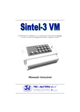
ITALIANO
ITALIANO
Combinatori telefonici GSM
con messaggi vocali
TDC26 - TDC36 - TM26GSM TM66GSM - ERMES2
MANUALE PER L'UTENTE
(per circuiti 619aMA-1.xx, 622aMA-1.xx)
TDC26-TDC36-TM26GSM-TM66GSM-ERMES2- Manuale per l'utente
Indice
Capitolo 1
Introduzione
3
1.1 Caratteristiche funzionali ..................................................................................................3
1.2 Caratteristiche tecniche ....................................................................................................3
Capitolo 2
2.1
2.2
2.3
2.4
Capitolo 3
Installazione
4
Collegamenti TDC26 ........................................................................................................4
Cellegamenti ERMES2,TM66GSM,TDC36,TM26GSM....................................................5
Collegamento antenna (ERMES2-TM66GSM-TM26GSM-TDC36)..................................6
Connessione alla linea GSM ............................................................................................7
Programmazione
8
3.1
3.2
3.3
3.4
3.5
3.6
Accesso alla programmazione..........................................................................................9
Rubrica ...........................................................................................................................10
Mess. Vocali....................................................................................................................12
Messaggi TXT/SMS........................................................................................................14
Canali ...........................................................................................................................15
Uscite ...........................................................................................................................17
3.6.1 Modo ..................................................................................................................17
3.6.2 Input Riferim.......................................................................................................18
3.6.3 Durata Impulso...................................................................................................18
3.7 Parametri ........................................................................................................................19
3.7.1 Controllo Remoto ...............................................................................................19
3.7.2 Scelta della lingua ..............................................................................................20
3.7.3 Impulsi Risposta.................................................................................................20
3.7.4 Num Chiamate ...................................................................................................21
3.7.5 Num. Messaggi ..................................................................................................21
3.8 Codici ...........................................................................................................................22
3.9 Info
...........................................................................................................................23
3.10 Ripristino impostazioni di default ....................................................................................23
Capitolo 4
Funzionamento
24
4.1 Descrizione generale del funzionamento........................................................................24
4.2 Controllo locale ...............................................................................................................25
4.2.1 STOP CICLO .....................................................................................................25
4.2.2 STOP TOT CICLI ...............................................................................................25
4.2.3 COMANDI USCITE............................................................................................26
4.2.4 STATO INGRESSI .............................................................................................27
4.2.5 FUORI SERVIZIO ..............................................................................................27
4.2.6 IN SERVIZIO......................................................................................................28
4.2.7 TELEFONA ........................................................................................................28
4.2.8 CONTROLLO REMOTO ....................................................................................29
2
Introduzione
1
Introduzione
1.1
Caratteristiche funzionali
!
!
!
!
!
!
!
!
!
!
!
Microfono incorporato
Modulo GSM dual band
Ritardo programmabile singolarmente sugli ingressi
Possibilità di abbinare ogni numero telefonico ad un solo canale, alcuni canali o a tutti i canali
Tamper di protezione antiapertura
Ascolto ambientale da remoto con funzione “viva voce”
Menù di programmazione multilingua : Italiano,Inglese,Francese,Tedesco,Spagnolo,Portoghese.
Numero di ripetizioni messaggio e cicli di chiamata programmabili
Indicazione dell'intensità di segnale GSM e del gestore telefonico
Mascheramento ID chiamante
Funzione CLIP: attivazione di una uscita tramite un solo squillo(chiamata senza risposta) da uno dei telefoni
Presenti in rubrica SMS, con relativo re-invio di uno squillo di conferma
1.2
Caratteristiche tecniche
TDC26
Messaggi SMS (128 car.)
Messaggi sul display (16 car.) per il monitoraggio
dello stato degli ingressi e delle uscite
Codici operatore programmabili
(Codice MASTER e Codice COMANDI)
Canali
Tensione nominale di alimentazione
Assorbimento massimo
Assorbimento in standby
Messaggi vocali (16 sec.)
Messaggi vocali di stato (2 sec.) per il monitoraggio
dello stato degli ingressi e delle uscite
Rubrica
Vano per batteria
Alimentatore / caricabatteria
Ingressi programmabili in modo impulso o stato,
condizionabili agli altri ingressi
Ingressi condizionamento INT
Uscite relè a scambio programmabili
Uscite a collettore aperto 100mA max.
Contenitore esterno
Dimensioni (L)
Dimensioni (A)
Dimensioni (P)
TDC36
2
12
ERMES2
6
28
TM26GSM TM66GSM
2
6
12
28
2
2
6
12Vcc±10%
400mA
70mA
7
28
3
12
16numeri
12V7Ah (non inclusa)
AL1 (incluso)
2
6
2
1
5
1
ABS
140mm
115mm
29mm
280mm
230mm
96mm
2
6
3
12
7
28
2
6
1
5
metallico
285mm
95mm
17mm
3
TDC26-TDC36-TM26GSM-TM66GSM-ERMES2- Manuale per l'utente
2 Installazione
2.1
Collegamenti TDC26
Questo collegamento permette
l’inserimento ed il disinserimento
della centrale antifurto sia tramite
la chiave elettronica,
sia tramite combinatore telefonico.
NOTA: se si utilizza solo il combinatore
telefonico è necessario collegare
solo le uscite C ed NC del Relè1
del combinatore sui morsetti Chiave
della centrale.
Chiave
elettronica
Relè 2
(opzionale)
Centrale
antifurto
Diodo
1N4004 o
simili
TDC26
OUT1
C
NA
JP
OUT2
Int1
IN K1
IN K2
12Vcc
STENDERE COMPLETAMENTE
IL FILO DELL‘ANTENNA PER
2MT PRIMA DI DARE
TENSIONE ALL’APPARECCHIO
Esempio di attivazione canale 2
*
In serie
alla 24h
Selezionare
tramite jumper il
funzionamento del
morsetto JP
Tasto di
Accesso alla
programmazione
mediante RESET
INT2
OUT1 NC
Connettere l’antenna
contenuta nella confezione .
Le antenne possono essere
distanziate ulteriormene
tramite la prolunga
di 5 mt PR-ANT
(NON INSTALLARE
PIÙ DI UNA PROLUNGA).
4
1.Tramite l’utilizzo di un qualsiasi telefono GSM
è necessario eliminare il codice di accesso
(codice PIN) che abilita l’utilizzo della SIM card;
2.Inserire la SIM card all’interno
del modulo tenendo
conto dell’angolo smussato
3.NON
FORZARE LA SIM.
Il fondo del TDC26 può essere montato su una comune
cassetta murale tipo “503”.
Intstallazione
2.2
Collegamenti ERMES2 / TM66GSM / TDC36 / TM26GSM
ERMES2 / TM66GSM / TDC36 / TM26GSM
SETUP
Tamper
Int1 Int2 K1 K2 K3 K4 K5 K6
C1 NA1 NC1 U2 U3 U4 U5 U6
OUT6
OUT5
OUT3
OUT4
OUT2
IN2
IN3
IN4
IN5
IN6
IN1
INT1
OUT1
12V
Esempio di
attivazione
canali 2÷6
Centrale
antifurto
per ERMES2
e TM66GSM
ATTENZIONE!
Per utilizzare le uscite
positive ‘+ Sir’ e ‘+ Int.’
della centrale il negativo
deve essere in comune
all’alimentazione
dell’ERMES2 / TM66GSM
+ Sir.
+ Int.
solo
per ERMES2
Chiave
elettronica
Nero
Rosso
Sezionatore
Rete
230V~
50Hz
Questo collegamento permette
l’inserimento ed il disinserimento
a distanza della centrale antifurto
unitamente
all’utilizzo della chiave
elettronica.
Bianco
Questo collegamento, se utilizzato, consente di
inviare ad uno degli ingressi (K1,K2...) un positivo
di riferimento in presenza della tensione di rete 230Vac.
Impostando nella programmazione l’ingresso come
“Livello Positivo”, al mancare della tensione di rete il
combinatore invierà il messaggio di allarme relativo.
solo
nell’ERMES 2
e nel TDC36
5
TDC26-TDC36-TM26GSM-TM66GSM-ERMES2- Manuale per l'utente
2.3
Collegamento antenna (ERMES2 - TM66GSM - TDC36 TM26GSM)
1.Tramite l’utilizzo di un qualsiasi
telefono GSM è necessario
eliminare il codice di accesso
(codice PIN) che abilita l’utilizzo
della SIM card;
2.Inserire la SIM card all’interno
del modulo tenendo
conto dell’angolo smussato.
NOTA: Non forzare la SIM.
Connettere l’antenna con
cavo da 2 mt ANTGSM4.
Le antenne possono essere
distanziate ulteriormene
tramite la prolunga
di 5 mt PR-ANT
(NON INSTALLARE
PIÙ DI UNA PROLUNGA).
ATTENZIONE:
LA SIM UNA VOLTA INSERITA FUORIESCE
DI CIRCA 4MM DAL CIRCUITO
NON FORZARE LA SIM!!
6
Intstallazione
2.4
Connessione alla rete GSM
Il modulo GSM funziona con una comune SIM Card GSM. Se all’accensione del
combinatore viene visualizzata la seguente schermata:
__INSERIRE_SIM
significa che non è stata inserita la SIM card all’interno del modulo GSM, oppure è stata
inserita in modo errato. Quindi SPEGNERE IL COMBINATORE, e procedere all’inserimento
della SIM card come indicato nei paragrafi precedenti.
Una volta inserita la scheda GSM, all’accensione del combinatore, o in caso di reset,
viene avviata la ricerca della rete GSM ed il display visualizza il seguente messaggio:
Registrazione...
Al termine della ricerca, se il combinatore è connesso alla rete GSM verrà visualizzato lo
stato della registrazione come visualizzato di seguito:
Intensità di campo bassa
05¥__TIM
Intensità di campo massima
30¥__TIM
Il LED rosso “GSM” presente sul pannello indica l'attività del modulo GSM;
!
!
!
!
Spento: GSM non operativo
Acceso: GSM procedura di avvioe e registrazione
Un flash al secondo: GSM registrato ed in attesa
Lampeggiante: GSM telefonata in corso
Il LED verde “Status”, invece, indica il controllo che il combinatore effettua sul modulo
GSM
7
TDC26-TDC36-TM26GSM-TM66GSM-ERMES2- Manuale per l'utente
3
Programmazione
Nei menù è possibile operare in due modalità differenti:
! utilizzando i tasti:
!
ad esempio:
!
oppure
fino a visualizzare la voce desiderata
e premendo:
Init_GSM_.......
8-PROGRAMMAZIONE
oppure
oppure
!
utilizzando il tasto di scelta rapida:
(Programmazione)
Ciò è valido sia nel Menù Principale, per accedere ad un qualsiasi sottomenù, sia
all'interno dei vari sottomenù, dove è inoltre possibile utilizzare i tasti di scelta rapida
per selezionare un determinato parametro, un determinato impianto, e così via.
NOTA Nel manuale, nella maggior parte dei casi, sarà utilizzata la modalità
con i tasti di scelta rapida. In tal modo, durante la consultazione del
manuale, sarà possibile utilizzare la sequenza di tasti presente a
fianco ad ogni Paragrafo per accedere velocemente alla
programmazione descritta al suo interno.
È possibile in ogni caso abbandonare la programmazione digitando
oppure
Una volta effettuata l’installazione e data la tensione al combinatore selezionare
la lingua desiderata utilizzando i tasti
oppure
e premere il tasto
oppure .
Le lingue disponibili sono Italiano, Inglese, Francese, Spagnolo, Portoghese,
Tedesco.
Dopo aver selezionato la lingua del combinatore,in condizione di stand/by
visualizzano lo stato, a rotazione, dei due canali di ingresso (di default CH1 è abilitato
e CH2 è disabilitato di default).
! Viene visualizzato:
che si alterna con:
25¥ TIM
Ch1 Rubrica Off
25¥ TIM
Ch1 Disabilitato
Una volta inserita la SIM il combinatore effettuerà la registrazione alla rete del
gestore telefonico visualizzando:
8
Programmazione
Registrazione...
CH1_Rubrica_Off
! Appena effettuata la registrazione viene visualizzato:
10¥_TIM
CH1_Rubrica_Off
Per attivare un ciclo di chiamate su un canale è necessario che vi sia abilitato
almeno un numero telefonico:la voce “Ch1 Rubrica OFF” indica che al canale 1 non è
associato alcun numero telefonico né per le chiamate vocali, né per l’invio degli SMS
e pertanto risulta non operativo.
3.1
Accesso alla programmazione
La programmazione del combinatore è consentita soltanto dalla tastiera locale
digitando il codice MASTER (
)
! Digitare il codice:
! Premere il tasto:
! Viene visualizzato:
(Codice default MASTER)
(Programmazione)
_PROGRAMMAZIONE
1-Rubrica
La programmazione del combinatore prevede:
!
!
!
!
!
!
!
!
!
!
Rubrica Voce
16 numeri telefonici a cui saranno inoltrati i Messaggi Vocali.
Messaggi Vocali 3 da 16 secondi (messaggio comune, canale 1, canale 2) + 12 messagi di stato da
2 secondi ciascuno.
Messaggi Testo Descrizioni stato ingressi e uscite.
Canali
Impostazione degli ingressi, delle condizioni e dei ritardi di attivazione.
Messaggi Vocali 6(nell’ERMES2 e nel TM66GSM) o 2 (nel TDC36, nel TDC26 e nel TM26GSM)
di stato
messaggi vocali di 15 secondi relativi alle attivazioni dei canali.
2 messaggi vocali di 2 secondi relativi ai due stati dell’ingresso INT.
12 (nell’ERMES2 e nel TM66GSM) o 4 (nel TDC36, nel TDC26 e nel TM26GSM)
messaggi vocali di 2 secondi relativi ai due stati di ogni ingresso.
12 (nell’ERMES2 e nel TM66GSM) o 4 (nel TDC36, nel TDC26 e nel TM26GSM)
messaggi vocali di 2 secondi relativi ai due stati di ogni uscita.
Messaggi SMS
6 (nell’ERMES2 e nel TM66GSM) o 2 (nel TDC36, nel TDC26 e nel TM26GSM)
SMS di 100 caratteri relativi alle attivazioni dei canali 2 SMS di 16 caratteri relativi
ai due stati dell’ingresso INT.12 (nell’ERMES2 e nel TM66GSM) o 4 (nel TDC36,
nel TDC26 e nel TM26GSM) SMS di 16 caratteri relativi ai due stati di ogni
ingresso.
12 (nell’ERMES2 e nel TM66GSM) o 4 (nel TDC36, nel TDC26 e nel TM26GSM)
SMS di 16 caratteri relativi relativi ai due stati di ogni uscita.
Uscite
Impostazione delle uscite.
Parametri
In questa sezione si improntano i parametri di funzionamento del combinatore.
Codici
Variazione del Codice MASTER e del Codice COMANDI.
Info
Visualizzazione informazioni del modello di combinatore e del firmware.
9
TDC26-TDC36-TM26GSM-TM66GSM-ERMES2- Manuale per l'utente
3.2
Rubrica
In questo menù è possibile inserire o modificare i numeri telefonici che il
combinatore deve chiamare in caso di attivazione di un canale.
! Digitare il codice:
! Premere il tasto:
! Premere il tasto:
! Viene visualizzato:
! Premere il tasto:
! Viene visualizzato:
! Premere il tasto:
(Codice default MASTER)
(Programmazione)
(Rubrica)
Numero___01
Num._01
oppure
Numero
Non Programmato
Numero
_
! Viene visualizzato:
! Digitare il numero da memorizzare e premere il tasto
>
! Una volta memorizzato il numero telefonico digitare il tasto
! Viene visualizzato:
! Premere il tasto:
! Viene visualizzato:
! Digitare il nome da memorizzare:
ad esempio:
Nome
Num. 01
Nome
Num. 01
>
2-Nome
Signor_Rossi
! Premere il tasto:
NOTA: La lunghezza massima del nome da inserire è di 16 caratteri.
10
Programmazione
Per comporre il testo del nome è sufficiente mantenere premuto uno dei tasti per
visualizzare in sequenza sul display le lettere serigrafate sul pannello; i caratteri
?!,.:;”’<=>()1
ABCabc2
DEFdef3
disponibili sono i seguenti:
GHIghi4
JKLjkl5
MNOmno6
PQRSpqrs7
TUVtuv8
WXYZwxyz9
*
[spazio] + & @ / % $ _ 0
*
NOTA: Per cancellare una lettera o un numero in fase di memorizzazione o
modifica utilizzare i tasti
oppure
per scegliere quale lettera o
numero e utilizzare il tasto
per cancellare.
! Una volta memorizzato il nome del numero telefonico digitare il tasto
premere il tasto
oppure .
! Viene visualizzato
e
Chiamata Voce
Canale
>--
Premere il tasto che corrisponde al numero del canale (es.
per il canale 1;
per il
canale 2, etc..). Per eliminare l’assegnazione è sufficiente digitare nuovamente il numero del
canale.
Una volta assegnato il canale premere il tasto
una volta per tornare indietro e
selezionare il successivo numero da memorizzare utilizzando i tasti
oppure .
Ripetere la stessa procedura appena citata per memorizzare gli altri numeri.
NOTA: Se nessun numero è inserito nella rubrica e assegnato ad almeno uno dei
canali (nel caso degli altri canali dovranno essere prima abilitati), il
combinatore visualizzerà rispettivamente per ogni canale nel display iniziale:
25¥ TIM
Ch1 Rubrica Off
! Una volta assegnato uno o più canali ad uno o più numeri telefonici digitare il
tasto
SMS
Canale___>--
! Viene visualizzato:
! Premere il tasto corrispondente al canale a cui si vuole assegnare l’sms.
! Viene visualizzato:
SMS
Canale___>1-
11
TDC26-TDC36-TM26GSM-TM66GSM-ERMES2- Manuale per l'utente
! Una volta assegnato uno o più canali ad uno o più numeri telefonici digitare il
tasto
! Viene visualizzato:
CLIP
Off
--
In questa voce del menù è possibile inserire l’operazione che il combinatore
esegue quando riceve una telefonata.
3.3
1
OUT1_OFF______--
Seleziona l’uscita 1
2
OUT2_OFF______--
Seleziona l’uscita 2
3
OUT3_OFF______--
Seleziona l’uscita 3
4
OUT4_OFF______--
Seleziona l’uscita 4
5
OUT5_OFF______--
Seleziona l’uscita 5
6
OUT6_OFF______--
Seleziona l’uscita 6
7
OUTX_ON_______--
Invia un comando ON sull’uscita selezionata
8
OUTX_OFF______CR
Abilita la chiamata di conferma
9
OUTX_OFF______--
Invia un comando OFF sull’uscita selezionata
0
Off
Disabilita il CLIP
Mess. Vocali
I messaggi vocali sono quelli che il combinatore utilizza per segnalare un allarme
oppure lo stato degli ingressi e delle uscite all’utente durante una connessione
telefonica.
! Digitare il codice:
(Codice default MASTER)
! Premere il tasto:
(Programmazione)
! Premere il tasto:
(Messaggi Vocali)
! Viene visualizzato:
! Tenere premuto il tasto:
! Viene visualizzato:
! Premere il tasto:
! Viene visualizzato:
Msg._COMUNE
*_Play_____#_Rec
(registrazione)
Msg._COMUNE
>>>>>>>>>>>>>>>>
(riproduzione)
Msg._COMUNE
>>>>>>>>>>>>>>>>
Nella pagina seguente è riportata una tabella dei messaggi vocali disponibili, indicati
nella parte superiore del display:
12
Programmazione
Messaggi
di allarme
Indicazione sulla prima riga del display
Msg._COMUNE
*_Play_____#_Rec
Canale_1
*_Play_____#_Rec
Canale_2
*_Play_____#_Rec
Durata:
Utilizzo:
16 sec.
E' trasmesso per primo durante
una chiamata di un ciclo di allarme
Segue il messaggio comune
quando si attiva il canale 1
Segue il messaggio comune
quando si attiva il canale 2
16 sec.
16 sec.
NOTA: i display dei canali arrivano a 6 per i modelli ERMES2, TM66GSM
Il messaggio inviato durante una chiamata a seguito dell'attivazione di un
canale è composto dal messaggio comune seguito dal messaggio specifico del
canale attivato, il tutto ripetuto per quante volte indicato dal parametro “Num Messaggi”
(vedi par. 3.7.5).
_NO
2 sec.
In_K1______
SI
*_Play_____#_Rec
In_K2___
___NO
2 sec.
In K2___
___SI
2 sec.
INT1__________NO
*_Play_____#_Rec
INT1__________SI
*_Play_____#_Rec
INT2__----_
NO
2 sec.
INT2_______
SI
2 sec.
Segnala l'ingresso
canale 1 non attivo
Segnala l'ingresso
canale 1 attivo
Segnala l'ingresso
canale 2 non attivo
Segnala l'ingresso
canale 2 attivo
Indica la mancanza della tensione
+12Volt sull'ingresso INT1
Indica la presenza della tensione
+12Volt sull'ingresso INT1
Indica la mancanza della tensione
+12Volt sull'ingresso INT2
Indica la presenza della tensione
+12Volt sull'ingresso INT2
Out_1_________NO
*_Play_____#_Rec
Out_1_________SI
*_Play_____#_Rec
Out_2_________NO
*_Play_____#_Rec
Out_2_________SI
2 sec.
Messaggio per uscita OUT1 non attiva
Messaggi
di stato
In_K1_____
2 sec.
2 sec.
2 sec.
2 sec.
Messaggio per uscita OUT1 attiva
2 sec.
Messaggio per uscita OUT2 non attiva
2 sec.
Messaggio per uscita OUT2 attiva
NOTA: Nei modelli ERMES2 e TM66GSM,i messaggi vocali di stato sono in totale 12
per gli ingressi + 4 per gli ingressi INT + 12 per le uscite.
I messaggi di stato sono utilizzati durante il controllo remoto per segnalare lo stato
degli ingressi e delle uscite e vengono trasmessi a seguito di un comando di
attivazione o interrogazione delle uscite, oppure a seguito di un comando di
interrogazione degli ingressi.
Una volta registrato selezionare il successivo messaggio vocale da memorizzare
utilizzando i tasti
oppure
e premere poi il tasto
oppure .e ripetere poi la stessa
procedura appena citata per memorizzare gli altri messaggi.
NOTA: Quando un canale viene allarmato, il combinatore effettua un ciclo di
chiamate a tutti i numeri inseriti nella Rubrica Voce abbinati a quel canale
per inoltrare il Messaggio Vocale relativo. Il parametro “Quantità Cicli”
descritto più avanti permette di stabilire quante volte tale ciclo di chiamate
dovrà essere ripetuto. Se durante l’invio del messaggio vocale si
digita “
”, il numero chiamato viene escluso dall’elenco delle
successive telefonate.
E’ consigliabile quindi inserire alla fine della registrazione dei Messaggi
Vocali di allarme una nota del tipo: “...Digitare cancelletto zero per non
ricevere più questo messaggio di allarme”.
13
TDC26-TDC36-TM26GSM-TM66GSM-ERMES2- Manuale per l'utente
3.4
Mess. TXT/SMS
In questo menù è possibile inserire o modificare gli SMS che il combinatore invia
in caso di allarme e le descrizioni che compaiono sul display per indicare lo stato degli
ingressi e delle uscite.
Le descrizioni verranno poi visualizzate quando si digitano sulla tastiera del
combinatore i comandi di interrogazione/comando per gli ingressi e per le uscite
(vedi par. 4.2.3).
! Digitare il codice:
! Premere il tasto:
! Premere il tasto:
(Codice default MASTER)
(Programmazione)
(Mess. Testo)
Canale
Ch. 1
! Viene visualizzato:
! Premere il tasto:
oppure
! Viene visualizzato:
! Digitare il messaggio da memorizzare
ad esempio:
1
Canale
Ch. 1
1
Canale 2
_
Irrigazione
>
! Premere il tasto:
Una volta digitato il messaggio utilizzare i tasti
oppure
per memorizzare gli altri.
oppure
e premere poi il tasto
Di seguito è riportata una tabella degli stati degli ingressi e delle uscite che sono
visualizzati nella parte superiore del display:
Canale___1____
Ch._1
In_K1________NO
*_Play_____#_Rec
In__K1_______SI
*_Play_____#_Rec
In_K2________NO
*_Play_____#_Rec
In_K2________SI
*_Play_____#_Rec
INT_1________NO
*_Play_____#_Rec
INT_1________SI
*_Play_____#_Rec
INT_2________NO
*_Play_____#_Rec
INT_2________SI
*_Play_____#_Rec
Out_1________NO
*_Play_____#_Rec
Out_1________SI
*_Play_____#_Re
Out_2________NO
*_Play_____#_Rec
Out_2________SI
*_Play_____#_Rec
14
Descrizione canale che verrà inviata tramite SMS
(da Ch1 ÷Ch2)TDC26, TDC36, TM26GSM / (da Ch1 ÷Ch 6) ERMES2, TM66GSM
Descrizione per ingresso canale 1 non attivo
Descrizione per ingresso canale 1 attivo
Descrizione per ingresso canale 2 non attivo
Descrizione per ingresso canale 2 attivo
Descrizione per tensione +12Volt su INT1 non presente
Descrizione per presenza della tensione di +12Volt su INT1
Descrizione per tensione +12Volt su INT2 non presente
Descrizione per presenza della tensione di +12Volt su INT2
Descrizione per uscita out1 non attiva
Descrizione per uscita out1 attiva
Descrizione per uscita out2 non attiva
Descrizione per uscita out2 attiva
Programmazione
3.5
Canali
In questo menù è possibile impostare come devono essere attivati i canali del
combinatore.
! Digitare il codice:
! Premere il tasto:
! Premere il tasto:
(Codice default MASTER)
(Programmazione)
(Canali)
! Viene visualizzato:
! Premere il tasto:
! Viene visualizzato:
! Premere il tasto:
! Viene visualizzato:
SELEZ._CANALE
Canale___1
oppure
Canale
1
1-Attivazione
oppure
1-Attivazione
Impulso NA
Scegliere tra i modi di attivazione raffigurati nella tabella sotto a quale condizione
il canale si deve allarmare utilizzando i tasti
oppure
. Premere poi il tasto
oppure .
1-Attivazione
Impulso_NA
1-Attivazione
Impulso_NC
1-Attivazione
Livello_NA
1-Attivazione
Livello_NC
1-Attivazione
Non_Attivo
Il canale è attivato dalla presenza di un positivo 12Vcc
all’ingresso del canale; il ciclo di chiamate
viene avviato ed effettuato fino al termine,
se non interrotto tramite comandi.
Il canale è attivato dall'assenza di un positivo 12Vcc
sull’ingresso del canale; il ciclo di chiamate
viene avviato ed effettuato fino al termine,
se non interrotto tramite comandi
Il canale è attivato dalla presenza di un positivo 12Vcc
sull’ingresso del canale;il ciclo di chiamate viene
eseguito fino al termine se non interrotto
da un comando o dal venire a mancare
del positivo dell’ingresso.
Il canale è attivo al mancare del positivo 12Vcc
sull’ingresso del canale; il ciclo di chiamate
viene eseguito fino al termine,
se non interrotto tramite comando o tramite il ripristino
del positivo 12Vcc sull'ingresso
Impulso NA
12V
0
Impulso NC
12V
0
Livello NA
12V
0
Livello NC
12V
0
Il canale non si attiva in nessuna condizione
e sul display
del combinatore viene visualizzato:
GSM.............
CH1_Disabilitato
15
TDC26-TDC36-TM26GSM-TM66GSM-ERMES2- Manuale per l'utente
Una volta scelta la condizione in cui il canale selezionato si allarma, è possibile
scegliere se condizionare o meno tale ingresso ad INT1, INT2 oppure a In K1, In K2.
“Condizionare” un ingresso significa farlo dipendere dalla presenza di un altro
positivo per renderlo operativo; al mancare di questa condizione l’ingresso non è
operativo o, se viene a mancare successivamente all’attivazione dell’ingresso,
genera l’arresto dei cicli in corso.
Esempio di programmazione ingresso IN K1 per attivazione ciclo o allarme
antifurto condizionato dall’inserimento della centrale (+INT):
! Impulso NA con +INT attivo
Il ciclo di chiamate parte se la centrale è inserita (INT attivo) e se va in
allarme (IN K1 attivato dal positivo di allarme della centrale).
In tal caso per arrestare il ciclo di chiamate del combinatore è sufficiente
disinserire la centrale da locale o da remoto.
! Impulso NA con impulso disattivo
In tal caso per arrestare il ciclo di chiamate agire sul combinatore oppure
attendere il termine dei cicli.
! Premere il tasto
! Viene visualizzato:
2-Input
INT1
INT
Utilizzare i tasti
oppure
per scegliere quale ingresso (IN1; INT1; IN2; INT2
rappresentati nella tabella sotto) usare come “Input INT”. Premere poi il tasto
Interdetto
oppure
INT1
Interdetto
INT2
Interdetto
In_K1
Interdetto
In_K2
Interdetto
Off
Ingresso INT 1
Ingresso INT 2
Ingresso canale 1
Ingresso canale 2
Nessuna condizione
NOTA: non è possibile usare In K1 come “Input INT” del canale 1 e In K2
come “Input INT” del canale 2.
Una volta indicato a quale ingresso dipende la funzione dell’ ingresso positivo
interrotto per ogni canale è possibile inserire un ritardo fra il segnale di attivazione del
canale e l'inizio effettivo del ciclo di chiamate.
! Premere il tasto
! Viene visualizzato:
! Premere il tasto oppure
! Viene visualizzato:
16
3-Ritardo
0000
3-Ritardo
----
Programmazione
Digitare il ritardo con la tastiera che è di 9999 secondi massimo (pari a 2h 46' 39”)
e premere il tasto
oppure
.
NOTA: Se durante il tempo di ritardo interviene un evento che annulla il ciclo, il
timer del ritardo viene ricaricato, ed un eventuale nuova attivazione
ricomincia il conteggio daccapo.
3.6
Uscite
In questo menù è possibile impostare i parametri di funzionamento delle uscite
che sono: Modo, Input Riferim. e Durata Impulso.
! Digitare il codice:
! Premere il tasto:
! Premere il tasto:
6
(Codice default MASTER)
(Programmazione)
(Uscite)
SELEZ._USCITA
Out_1
! Viene visualizzato
Selezionare l’uscita (da 1 a 2 per TDC26, TDC36, TM26GSM e da 1 a 6 per
ERMES2, TM66GSM) premendo i tasti
oppure . Premere poi il tasto
oppure
3.6.1
Modo
Una volta selezionata l’uscita bisogna impostarne il comportamento quando
riceve un comando di attivazione o di disattivazione (vedi par. 4.2.3).
Out_1
Modo
! Viene visualizzato
! Premere il tasto
oppure
Utilizzare i tasti
oppure
poi il tasto
oppure .
Modo
ON/OFF
Modo
IMPULSO
Modo
TOGGLE
per scegliere il “Modo” (vedi tabella sotto). Premere
Il comando ON inverte lo stato dell’uscita se questa risulta disattiva
e non ha effetto se risulta già attiva. Viceversa il comando OFF
commuta l’uscita solo se questa risulta attiva. Per valutare la condizione
dell'uscita (se è attiva o disattiva), il combinatore fa riferimento alla condizione
dell'uscita stessa o dell'ingresso di riferimento in accordo
a quanto impostato nell'opzione “Input Riferim” (vedi par. 3.6.2).
Il comando ON genera un impulso sull’uscita se questa risulta disattiva
e non ha effetto se risulta già attiva. Viceversa il comando OFF
commuta l’uscita solo se questa risulta attiva.
Anche in questa modalità lo stato dell'uscita (attivo o disattivo) dipende
da come si imposta il parametro per l'ingresso di riferimento.
La differenza rispetto alla modalità precedente consiste
che l'operazione che viene eseguita non è quella della commutazione,
ma è la generazione di un impulso off-on-off, della durata impostata
nel parametro “Durata Impulso” (vedi par. 3.6.3).
Con questa scelta i comandi ON e OFF hanno sempre l'effetto di invertire lo stato
dell'uscita indipendentemente dalla sua condizione.
17
TDC26-TDC36-TM26GSM-TM66GSM-ERMES2- Manuale per l'utente
3.6.2 Input Riferim.
L’ingresso di riferimento è usato per la valutazione dello stato dell’ uscita (attiva o
disattiva), sia per l’esecuzione dei comandi sulle uscite, sia per determinare le
indicazioni sui display o i messaggi vocali da inviare in caso di interrogazione da
remoto.
! Premere il tasto:
Input_Riferim.
INT1
! Viene visualizzato:
Utilizzare i tasti
oppure
per scegliere quale “Input Riferim.” (vedi tabella
sotto) è utilizzato per determinare lo stato dell’uscita. Premere poi il tasto
oppure
.
Interdetto
In K1
Interdetto
In K2
Interdetto
Int 1
Interdetto
Int 2
Lo stato dell'uscita è determinato con riferimento all'ingresso K1: con una tensione
di 12V presente sull'ingresso K1 il combinatore considera
l'uscita attiva, mentre in mancanza di tale tensione valuta l'uscita disattiva
L'uscita fa riferimento all'ingresso K2
L'uscita fa riferimento all'ingresso INT1
L'uscita fa riferimento all'ingresso INT2
In questo caso l'uscita non fa riferimento ad un ingresso, ma lo stato di attivo
e disattivo è determinato dalla condizione stessa dell'uscita:
OUT1 si attiva quando il relè di uscita collega i morsetti Ce NA
mentre OUT2 è attiva quando attraverso
il morsetto può circolare corrente verso il negativo di alimentazione
Interdetto
Nessun_Input
3.6.3 Durata Impulso
Imposta la durata dell’impulso generato sull’uscita espressa in secondi. Se
l’uscita non è programmata in modo ad impulsi questo valore è ignorato.
! Premere il tasto:
Durata_Impulso
01
! Viene visualizzato:
! Premere il tasto
oppure
Durata_Impulso
--
! Viene visualizzato:
Selezionare la durata dell’implulso con la tastiera che è da 1÷99 secondi.
! Premere il tasto
18
oppure
Programmazione
3.7
Parametri
In questa sezione si impostano i paremetri di funzionamento del combinatore.
! Digitare il codice:
! Premere il tasto:
! Premere il tasto:
(Codice default MASTER)
(Programmazione)
(Parametri)
Contr._Remoto
On
! Viene visualizzato:
Utilizzare i tasti
oppure
Premere poi il tasto
oppure .
per scegliere quale parametro impostare.
NOTA: Nei sottoparagrafi che seguono vengono spiegati i funzionamenti dei
singoli parametri e come raggiungerli dal menù principale
direttamente con una combinazione di tasti.
3.7.1 Contr. Remoto
Con questo parametro si abilita/disabilita il combinatore ad accettare il controllo
da remoto.
NOTA: se si disabilita questo parametro il combinatore non risponde alle
chiamate provenienti dall'esterno e non accetta i comandi di
attivazione o interrogazione degli ingressi e delle uscite durante le
chiamate di allarme.
!
!
!
!
Digitare il codice:
Premere il tasto:
Premere il tasto:
Premere il tasto:
(Codice default MASTER)
(Programmazione)
(Parametri)
(Contr. Remoto)
! Viene visualizzato:
Premere il tasto
oppure
Contr._Remoto
On
per attivare o disattivare il parametro.
19
TDC26-TDC36-TM26GSM-TM66GSM-ERMES2- Manuale per l'utente
3.7.2 Scelta della lingua
In questo menù è possibile cambiare la lingua che il combinatore telefonico
utilizza per le indicazioni nel display..
!
!
!
!
!
Digitare il codice:
Premere il tasto:
Premere il tasto:
Premere il tasto:
Premere il tasto:
(Codice default MASTER)
(Programmazione)
(Parametri)
(Lingua)
oppure
Lingua
Italiano
! Viene visualizzato:
NOTA: Alla prima accensione il combinatore richiede la scelta della lingua da
utilizzare.Le lingue disponibili sono: Italiano, Inglese, Francese,
Spagnolo, Portoghese, Tedesco.
Selezionare la lingua desiderata utilizzando i tasti
tasto
oppure .
3.7.3
oppure
e premere il
Impulsi Risposta
Indica il numero di squilli che il combinatore attende prima rispondere alla
chiamata quando è abilitato il controllo remoto.
!
!
!
!
Digitare il codice:
Premere il tasto:
Premere il tasto:
Premere il tasto:
(Codice default MASTER)
(Programmazione)
(Parametri)
(Impulsi Risposta)
Impulsi_Risposta
02
! Viene visualizzato:
! Premere il tasto:
oppure
Impulsi_Risposta
--
! Viene visualizzato:
Selezionare il numero di impulsi da 0 ÷ 40 secondi.
! Premere il tasto
oppure
NOTA: Il combinatore non accetta un numero superiore a 40. Se si imposta 00
il combinatore non risponde alle chiamate esterne.
20
Programmazione
3.7.4
Num. Chiamate
Questo parametro imposta quanti tentativi di chiamata il combinatore esegue per
ogni numero della rubrica in un ciclo di allarme.
! Digitare il codice:
(Codice default MASTER)
! Premere il tasto:
(Programmazione)
! Premere il tasto:
(Parametri)
! Premere il tasto:
(Num. Chiamate)
! Viene visualizzato:
! Premere il tasto:
! Viene visualizzato:
Num._Chiamate
3
oppure
Num._Chiamate
-
Selezionare il numero di chiamate (massimo 9).
! Premere il tasto
oppure
NOTA: Se durante la connessione si dà dal telefono connesso un comando di
“STOP CHIAMATA CORRENTE” (vedi par. 4.2.8), la chiamata non
viene più ripetuta nel seguito del ciclo. Con un comando di “STOP
CICLO IN CORSO” o di “STOP TUTTI I CICLI”, nessuna chiamata
viene più eseguita per il ciclo corrente o per tutti i cicli attivi (vedi par.
4.2.8).
3.7.5
Num. Messaggi
Questo parametro indica quante volte i messaggi vocali (messaggio comune +
messaggio di canale) vengono ripetuti ad ogni chiamata.
!
!
!
!
Digitare il codice:
Premere il tasto:
Premere il tasto:
Premere il tasto:
! Viene visualizzato:
! Premere il tasto:
! Viene visualizzato:
(Codice default MASTER)
(Programmazione)
(Parametri)
(Num. Messaggi)
Num._Messaggi
3
oppure
Num._Messaggi
-
Digitare il numero di messaggi vocali (massimo 9).
! Premere il tasto
oppure
NOTA: Dopo qualche secondo dal termine dei messaggi se non interviene il
controllo remoto la comunicazione è interrotta.
21
TDC26-TDC36-TM26GSM-TM66GSM-ERMES2- Manuale per l'utente
3.8
Codici
Il combinatore gestisce due codici entrambi di 4 cifre, uno MASTER ed uno
COMANDI.
Utilizzando il codice MASTER si ha il controllo totale del combinatore con
l'accesso ai comandi locali e da remoto e con la possibilità di programmare lo stesso
combinatore.
Utilizzando invece il codice COMANDI si hanno alcune limitazioni: non sono
consentiti i comandi locali di Stop totale cicli di allarme,messa in stato di fuori servizio
e di ripristino in servizio,di accesso alla programmazione e alla funzione “Telefona”
nonché i comandi remoti di Stop ciclo in corso,Stop totale cicli,Ascolto ambientale
con viva voce.
! Digitare il codice:
! Premere il tasto:
! Premere il tasto:
! Viene visualizzato:
! Premere il tasto:
! Viene visualizzato:
(Codice default MASTER)
(Programmazione)
(Codici)
SELEZ._CODICE
CODICE_MASTER
oppure
CODICE_MASTER
----
Digitare il codice MASTER da memorizzare e premere il tasto
oppure
Una volta assegnato il codice MASTER utilizzare i tasti
oppure
premere poi il tasto
oppure
per assegnare il codice COMANDI.
! Viene visualizzato:
! Premere il tasto:
! Viene visualizzato:
.
e
SELEZ._CODICE
CODICE_COMANDI
oppure
CODICE_COMANDI
----
Digitare il codice COMANDI da memorizzare e premere il tasto
oppure .
NOTA: quando il codice non è abilitato ad accedere ad un menù si
visualizzerà la scritta “NON PERMESSO” sul display.
NOTA: la lunghezza massima sia del codice MASTER che del codice
COMANDI da inserire è di 4 numeri.
In caso di smarrimento del codice MASTER,è possibile accedere
direttamente alla programmazione del combinatore mantenendo premuto il
tasto SETUP per 15 secondi (vedi par. 2.1).
22
Programmazione
3.9
Info
In questa parte sono radunate le informazioni utili per l'individuazione del
modello di combinatore e la release del firmware. Queste informazioni possono
essere richieste dal servizio di assistenza alla clientela per poter facilmente
individuare il prodotto e dare gli opportuni suggerimenti per il suo uso.
!
!
!
!
!
!
!
Digitare il codice:
Premere il tasto:
Premere il tasto:
(Codice default MASTER)
(Programmazione)
(Info)
Modello
__2_Canali_GSM
Viene visualizzato:
Premere il tasto:
oppure
Rel._Firmware
619aSW-1.01
Viene visualizzato:
Premere il tasto:
oppure
IMEI...
000000000000000
Viene visualizzato:
3.10
Ripristino impostazioni di default
Per riportare il combinatore alle impostazioni di default bisogna operare in questa
sequenza:
! togliere l’alimentazione
! Mantenere premuto il pulsante setup sul circuito (vedi par. 2.1)
! ridare alimentazione al combinatore
! rilasciare il pulsante setup
! premere 5 volte il tasto
entro 10 secondi
Le impostazioni di default sono:
Rubrica
Descrizione per numeri in Rubrica
Messaggi vocali
Messaggi testo
Canale 1
Canale 2
Uscita 1
Uscita 2
Contr. Remoto
Impulsi risposta
Num. Chiamate
Num. Messaggi
Codice MASTER
Codice COMANDI
Lingua
nessun numero programmato
“numero 01...16”
tutti cancellati
descrizione uguale alla prima riga del display
Attivazione: Impulso NA; Input INT: In INT 1; Ritardo: 0000
Attivazione: Non attivo; Input INT: Off; Ritardo: 0000
Modo: ON/OFF; Input Riferim.: In INT1; Durata impulso: 01
Modo: ON/OFF; Input Riferim.: Nessun Input; Durata impulso: 01
ON
03
3
3
1234
5678
non modificata
23
TDC26-TDC36-TM26GSM-TM66GSM-ERMES2- Manuale per l'utente
4
Funzionamento
L'uso del combinatore GSM è facilitato dalla presenza del display che fornisce
informazioni sulle attività e sullo stato del combinatore. La retroilluminazione del
display è gestita automaticamente: si attiva quando l'utente digita un qualsiasi tasto o
si attiva un canale e si spegne trascorsi 20 secondi circa dal termine di tutte le
operazioni.
Le informazioni sono visualizzate su due righe; sulla prima appaiono quelle
relative allo operazioni del combinatore sulla linea telefonica, mentre sulla seconda
le indicazioni riguardano lo stato dei canali.
Prima riga del display:
! Init GSM....
! INSERIRE SIM
! REGISTRAZIONE..
! 20¥
TIM
! 20¥
! 20¥
! 20¥
!
!
!
!
Chiama..
Ch. fallita
Occupato
20¥
20¥
20¥
Ric.
Invio SMS
Fine chiam.
Connesso
Chiamata
Seconda riga del display:
! Chn Rubrica off
! Chn Disabilitato
! Chn Interdetto
! Chn In Attesa
! Chn Intervallo
! Chn Timer
0012
! Controllo Remoto
4.1
Inizializzazione del modulo di connessione telefonica
GSM
Il combinatore attende l’inserimento di una SIM card
Tentativo di registrazione sulla rete telefonica in corso
Indica l’avvenuta connessione con il gestore
telefonico specificato e segnala in particolare
l’intensità del segnale (da 1 a 30) con il simbolo ¥
lampeggiante
In corso un tentativo di chiamata telefonica
Il tentativo di chiamata non ha avuto risposta
Il numero chiamato risulta occupato oppure la
chiamata è stata rifiutata
Invio degli SMS in corso
La chiamata telefonica è conclusa
Connessione telefonica effettuata
Ricezione chiamata telefonica
Nessun numero telefonico è associato al canale
Il canale è non Attivo
Sull’ingresso Input INT programmato non è presente
la tensione di 12V
Il canale è pronto ed in attesa di un segnale di
attivazione
Piccola pausa tra una telefonata e l’altra
Conteggio del tempo rimanente fra l’attivazione del
canale e la partenza del ciclo di chiamate
Attivazione del controllo da remoto durante la
connessione
Descrizione generale del funzionamento
L'attivazione di un canale genera una sequenza di chiamate verso i numeri
telefonici inseriti nella Rubrica con l'invio del messaggio vocale
registrato,(messaggio comune + messaggio di canale),ripetuto tante volte quante
stabilito dal parametro “Num. messaggi”. L'intero ciclo di chiamate è ripetuto per il
numero di volte determinato dal parametro “Num. Chiamate”.
24
Funzionamento
4.2
Controllo locale
Attraverso la tastiera, oltre che per la programmazione, è possibile interagire con
il combinatore per attivare le sue uscite o interrogare i suoi ingressi.
Per accedere alle voci del menù di funzionamento indicate di seguito per il
controllo locale è necessario digitare il Codice MASTER (default “1234”), o il Codice
COMANDI (default “5678”).
Codice
MASTER COMANDI
!
!
!
!
!
!
!
!
!
1 - STOP CICLO - permette l’interruzione dei cilcli di chiamate
2 - STOP TOT CICLI - permette l’interruzione della chiamata corrente
3 - COMANDI USCITE - permette il controllo diretto delle uscite
4 - STATO INGRESSI - permette il monitoraggio dello stato degli ingressi
6 - FUORI SERVIZIO - permette la messa in fuori servizio
7 - IN SERVIZIO - permette la messa in servizio
8 - PROGRAMMAZIONE - permette la programmazione del combinatore
9 - TELEFONA - permette l'uso in locale del combinatore come telefono GSM
0 - STOP CHIAMATA - permette l’interruzione della chiamata corrente
4.2.1
•
•
•
•
•
•
•
•
•
•
/
•
•
/
/
/
/
•
STOP CICLO
Questa opzione arresta qualsiasi ciclo di chiamate che sia stato attivato su
qualsiasi canale. Il ciclo si arresta anche quando gli ingressi sono programmati in
modalità “Livello NA” o “Livello NC” e quando lo stato di attivazione permane (vedi
par. 3.5).
! Digitare il codice:
! Premere il tasto:
(Codice default MASTER)
COMANDO_ESEGUITO
! Viene visualizzato:
4.2.2
STOP TOT CICLI
Annulla tutti i cicli di chiamate sia quello in corso che quelli eventualmente in
attesa, e chiude la connessione in corso
! Digitare il codice:
! Premere il tasto:
(Codice default MASTER)
(Stop totale cicli)
COMANDO_ESEGUITO
! Viene visualizzato:
25
TDC26-TDC36-TM26GSM-TM66GSM-ERMES2- Manuale per l'utente
4.2.3 COMANDI USCITE
oppure
Da accesso all'interrogazione e al comando delle uscite. Se il combinatore non è
allarmato e si digita un codice di accesso, questa è la voce del menù che appare sul
display.
! Digitare il codice:
! Premere il tasto:
! Viene visualizzato:
(Codice default MASTER)
(Comandi Uscite)
Out_1
Antifurto_____NO
Descrizione degli stati degli ingressi e delle uscite (vedi par. 3.4)
A tal punto, utilizzare i tasti
e
per comandare l’uscita secondo la sua
programmazione (vedi par. 3.6):
! Se l’uscita è impostata “ON/OFF”, il tasto
!
!
!
attiva l’uscita ed il tasto
la
disattiva.
Se l’uscita è impostata “TOGGLE”, sia il tasto
che il
invertono lo stato
dell’uscita.
Se l’uscita è impostata “IMPULSO”, sia il tasto
che il
creano un impulso
sull’uscita.
Se l’uscita è impostata anche su “input Rif.” il funzionamento dei tasti
e
è
condizionato dallo stato dell'ingresso di riferimento (vedi par. 3.6.1 e 3.6.2.).
Nell’esempio di installazione (vedi par. 2.1) il relè della chiave elettronica ed il relè
del combinatore sono interconnessi per inserire e disinserire l’impianto antifurto
tramite entrambe i dispositivi; in tal modo, infatti, l'inversione di stato di ognuno dei
relè provoca l'inserimento o il disinserimento dell'impianto.
Ciò comporta, quindi, che l’attivazione del relè del combinatore NON corrisponde
sempre all’inserimento dell'impianto.
Per operare un comando di inserimento è quindi necessario conoscere l'effetivo
stato della centrale tramite la sua uscita "+Int" collegata all’ingresso "INT" del
combinatore. In tal modo, digitando
per l'inserimento, il combinatore scambierà lo
stato del proprio relè solo se la centrale risulterà disinserita, altrimenti non vi sarà
effetto; di conseguenza non verrà visualizzato il messaggio relativo allo stato
dell’uscita relè, ma bensì lo stato dell’ingresso "INT" da cui il relè dipende, per
indicare lo stato reale dell'impianto. Quindi, se il display visualizza
Antifurto_____ON
tale messaggio sarà relativo allo stato dell’ingresso "INT", ed un eventuale comando
corrisponderà semplicemente ad una inversione dello stato del relè, per visualizzare lo stato
risultante dell’ingresso:
Antifurto____OFF
26
Funzionamento
4.2.4
STATO INGRESSI
oppure
Accede alla visualizzazione dello stato degli ingressi.
! Digitare il codice:
(Codice default MASTER)
oppure
(Codice default
COMANDI)
(Stato Ingressi)
! Premere il tasto:
In_K1
Irrigazione___NO
! Viene visualizzato:
Utilizzare i tasti
visualizzare lN1 e IN2.
oppure
oppure direttamente i tasti
oppure
per
Utilizzare i tasti
oppure
visualizzare lNT1 e INT2.
oppure direttamente i tasti
oppure
per
4.2.5
FUORI SERVIZIO
Con questo comando il combinatore azzera tutti i cicli di allarme e non accetta più
altre attivazioni. Una eventuale chiamata telefonica in corso al momento del
comando non viene interrotta, ma continua regolarmente fino alla sua regolare
conclusione. Le altre funzioni del combinatore rimangono operative, compresa la
risposta alle telefonate dall'esterno ed il comando e interrogazione degli ingressi e
delle uscite.
! Digitare il codice:
(Codice default MASTER)
! Premere il tasto:
(Fuori Servizio)
_FUORI_SERVIZIO
! Viene visualizzato per quelche secondo:
NOTA: Una volta dato questo comando il combinatore visualizzerà nel menù
iniziale il seguente display:
23¥ I TIM
FUORI SERVIZIO
NOTA: Questo comando è eseguibile solo digitando il codice MASTER.
27
TDC26-TDC36-TM26GSM-TM66GSM-ERMES2- Manuale per l'utente
4.2.6
IN SERVIZIO
Questo comando riporta il combinatore al suo normale funzionamento da una
condizione di fuori servizio
! Digitare il codice:
! Premere il tasto:
(Codice default MASTER)
(In Servizio)
__IN_SERVIZIO
! Viene visualizzato per pochi secondi:
NOTA: Questo comando è eseguibile solo digitando il codice MASTER.
4.2.7
TELEFONA
Consente di effettuare una chiamata in viva voce dal combinatore per provare il
corretto funzionamento della linea telefonica.
! Digitare il codice:
! Premere il tasto:
(Codice default MASTER)
(Telefona)
Inserire_numero
__
! Viene visualizzato
Selezionare il numero di telefono.
! Premere il tasto
! Viene visualizzato
oppure
23¥ Chiama....
0123456789
Numero di telefono selezionato
Il combinatore attende una risposta entro il decimo squillo, poi abortisce il
tentativo.
NOTA: Questo comando è eseguibile solo digitando il codice MASTER.
28
Funzionamento
4.2.8
CONTROLLO REMOTO
oppure
Il combinatore è in grado di interpretare i toni multi-frequenza DTMF generati
comunemente dagli apparecchi telefonici e quindi di eseguire comandi o inviare
informazioni durante una connessione telefonica.
Se si programma l'opzione “Contr. Remoto” in ON (vedi par. 3.7.1) e “Impulsi
Risposta”maggiore di zero (vedi par. 3.7.3) è possibile accedere al controllo remoto
sia telefonando direttamente al combinatore che durante una chiamata di allarme.
Per attivare il controllo remoto è necessario digitare un codice di accesso valido
(vedi par. 3.8) entro 10 secondi circa dalla connessione se la chiamata parte
dall'utente remoto oppure entro 10 secondi dalla fine dell'ultimo messaggio vocale
quando la chiamata parte dal combinatore.
Se il combinatore accetta il codice digitato trasmette tre beep in successione
lenta (circa 1 al secondo).
Quando si attiva il controllo remoto, sul display del combinatore compare sulla
seconda riga l'indicazione « GESTIONE REMOTA ».
! Digitare il codice dal telefono:
! Viene visualizzato sul combinatore:
! Digitare dal cellulare:
(Codice default MASTER)
oppure
(Codice default
COMANDI) (vedi par. 3.8)
Connesso_.......
GESTIONE_REMOTA
#0
STOP CHIAMATA CORRENTE
interrompe la chiamata in corso e annulla la chiamata per tutto il ciclo
Con questo comando il combinatore non esegue più la chiamata al numero
attuale nei successivi cicli di chiamate relativi all'attivazione del canale.
Il combinatore segnala il riconoscimento di questo comando con 5 beep in
rapida successione (circa 2 al secondo).
Questo comando non termina la comunicazione: per interromperla è
necessario digitare il comando “# # #”, oppure attendere la fine della
chiamata.
#1
STOP CICLO IN CORSO
interrompe il ciclo di chiamate relativi al singolo canale allarmato
Questo comando annulla il ciclo di chiamate corrente e comunica al
combinatore di non contattare i successivi numeri della rubrica.
Il riconoscimento di questo comando è segnalato tramite 5 beep in rapida
successione.
NOTA: Questo comando è eseguibile solo digitando il codice MASTER.
29
TDC26-TDC36-TM26GSM-TM66GSM-ERMES2- Manuale per l'utente
#2
STOP TUTTI I CICLI
interrompe il ciclo di chiamate relativi a tutti i canali allarmati.
Questa comando ferma sia il ciclo corrente che quello eventualmente in
attesa associato all'altro canale.
Il combinatore non esegue più telefonate ad altri numeri della rubrica, ma
ritorna in attesa di una successiva attivazione.
Il riconoscimento di questo comando è segnalato da 5 beep in rapida
successione.
NOTA: Questo comando è eseguibile solo digitando il codice MASTER.
#3
COMANDI USCITE (interrogazione / attivazione uscite)
consente di comandare le uscite.
Per comandare una uscita bisogna dapprima selezionarla:
digitare “1” per l'uscita OUT1 o “2” per OUT2 ed il combinatore invia il
messaggio registrato per lo stato dell'uscita selezionata.
Se si programma l'uscita in abbinamento ad un ingresso di riferimento (vedi
“Input Riferim.” par.3.6.2) il messaggio trasmesso è invece quello relativo allo
stato dell'ingresso di riferimento.
Questa configurazione è utilizzata generalmente quando il combinatore
comanda l'attivazione delle centrali antifurto con l'ingresso INT connesso al
positivo interrotto delle centrali.
In questo modo è possibile conoscere lo stato dell'uscita per l'inserimento
della centrale controllando direttamente lo stato di inserimento o
disinserimento.
Con il tasto “7” si invia il comando di attivazione dell'uscita selezionata e con il
tasto “9” quello di disattivazione. Al termine dell'esecuzione di questi comandi
il combinatore invia il messaggio relativo al nuovo stato dell’uscita.
Come già visto per il controllo da tastiera locale, un comando di attivazione
non ha effetto se l'uscita risulta già attiva, così come pure una disattivazione
non ha effetto se lo stato dell'uscita risulta già essere disattiva.
Se si digita un tasto diverso da quelli previsti per questo menù il combinatore
segnala l'errore con un beep lungo.
#4
INTERROGAZIONE STATO INGRESSI
Con questo comando è possibile interrogare il combinatore per conoscere lo
stato dei suoi ingressi attraverso i messaggi vocali. Al riconoscimento di
questo comando vengono emessi 3 beep.
Digitare 1 per l'ingresso IN
Digitare 2 per IN2
Digitare 7 per l'ingresso INT1
Digitare 8 per l'ingresso INT2
Il combinatore invia il messaggio registrato per lo stato dell'ingresso
selezionato.
NOTA: Digitando uno degli altri tasti non abilitati per questo comando, viene
emesso un beep lungo di segnalazione errore.
30
Funzionamento
#5
ASCOLTO AMBIENTALE CON VIVA VOCE
consente di ascoltare i rumori nell’ambiente in cui si trova l’apparato.
Il combinatore invia 3 beep di riconoscimento comando ed attiva la
connessione audio con l'apparecchio remoto.
Digitare “9” per attivare la comunicazione bidirezionale con viva voce (con
elevata sensibilità microfono)
Digitare “7” per attivare l’ascolto ambientale (riduce la sensibilita' microfono)
La connessione si interrompe dopo tre minuti; per ricominciare il conteggio dei
tre minuti, è necessario digitare un qualsiasi tasto e generare così un tono
multifrequenza. La connessione è interrotta se il combinatore riconosce un
segnale dalla centrale telefonica (ad esempio il tono di occupato) , o anche se
nessun rumore è captato dal microfono interno o attraverso il telefono
connesso, per un tempo superiore ai 20 secondi.
NOTA: Questo comando è eseguibile solo digitando il codice MASTER.
#6
FUORI SERVIZIO (CON STOP DI TUTTI I CICLI)
Arresta ogni funzionalità del combinatore. Sarà ancora possibile connettersi
al combinatore da remoto, se consentito dai parametri programmati, ed in
questo modo rimettere in servizio il combinatore oppure comandare o
interrogare gli ingressi e le uscite o attivare l'ascolto remoto.
Il riconoscimento è segnalato da 3 beep. Dopo i tre beep, è necessario digitare
nuovamente il codice MASTER. L'esecuzione del comando è infine
confermata con 5 beep in rapida successione.
#7
RIPRISTINO IN SERVIZIO
Riavvia ogni funzionalità del combinatore. Il combinatore conferma il
riconoscimento con tre beep.
NOTA: Questo comando è eseguibile solo digitando il codice MASTER.
### CHIUSURA CONNESSIONE
Alla ricezione di questo comando, accessibile anche senza digitare alcun
codice di accesso, il combinatore trasmette 5 beep e poi chiude la
connessione. Se questo comando è dato per terminare una connessione in un
ciclo di allarme, l'utente non è escluso dall'elenco di chiamate per il
proseguimento del ciclo. Se si desidera non ricevere più chiamate per il ciclo
di allarme in corso, occorre utilizzare il comando #0 (sottoposto però alla
digitazione del codice) e poi digitare ### per terminare la telefonata.
31
TDC26-TDC36-TM26GSM-TM66GSM-ERMES2- Manuale per l’utente
®
PROGETTAZIONI E PRODUZIONI ELETTRONICHE
Azienda con Sistema di
gestione per la Qualità
UNI EN ISO 9001:2000
COSTRUTTORE:
HiLTRON S.r.l.
INDIRIZZO:
Via Caserta al Bravo, 218 - 80144 - NAPOLI
Azienda con Sistema di
g e stio n e ambi ental e
UNI EN ISO 14001:2004
Sulla valutazione di prove eseguite su impianti campioni rispecchianti la configurazione
funzionale prevista per l'utilizzazione, risulta che i prodotti:
CODICE DEI PRODOTTI:
TDC26,TDC36,TM26GSM,ERMES2,TM66GSM
DESCRIZIONE DEI PRODOTTI:
COMBINATORE TELEFONICO GSM 6IN/6OUT CON MESSAGGI VOCALI
COMBINATORE TELEFONICO GSM 2IN/2OUT CON MESSAGGI VOCALI
MARCHIO UTILIZZATO:
Il marchio CIA è registrato dalla HiLTRON Srl
risultano conformi alla direttive di seguito indicate
EMC 89/336 CEE
MADE IN ITALY
DICHIARAZIONE DI CONFORMITA’
I SUDDETTI PRODOTTI SODDISFANO LE DIRETTIVE
RIPORTATE IN TABELLA CON RIFERIMENTO ALLE NORME COMUNITARIE.
DIRETTIVE
NORME DI RIFERIMENTO
EMC 89/336/CEE
EN50081-1 ; norma generica di emissione
EN50082-1 ; norma generica di immunità
BT 73/23/CEE e successive modifiche
EN60065 ; norma per la sicurezza delle apparecchiature elettriche
collegate alla rete d’uso domestico e analogo uso similare
Lead free
Pb
CONFORMITA’ RoHS
RoHS
compliant
Dichiarazione di conformità alle limitazioni dell’uso di sostanza pericolose regolamentate dalla direttiva
2002/95CE (RoHS) recepita con D.lgs 25 Luglio 2005 n°151 (Articolo 5).
Il prodotto è conforme alle disposizioni della direttiva su indicata sulle
restrizioni all’uso di alcune sostanze pericolose nelle apparecchiature elettriche ed elettroniche,ovvero
non le contengono in concentrazioni superiori ai margini previsti.
CONFORMITA’ RAEE
In alcuni paesi dell’Unione l prodotto non ricade nel campo di applicazione della legge nazionale
di recepimento della direttiva WEEE, e quindi non è in essi vigente
alcun obbligo di raccolta differenziata a fine vita
DATA
L’AMMINISTRATORE DELEGATO
01 Gennaio 2008
32
619ADI-1.01
ITALIANO
ENGLISH
GSM phone dialers
with vocal messages
TDC26 - TDC36 - TM26GSM TM66GSM - ERMES2
USER’S MANUAL
(for circuits 619aMA-1.xx, 622aMA-1.xx)
TDC26-TDC36-TM26GSM-TM66GSM-ERMES2- User’s manual
Index
Chapter 1
Introduction
3
1.1 Functional characteristics .................................................................................................3
1.2 Technical characteristics...................................................................................................3
Chapter 2
2.1
2.2
2.3
2.4
Chapter 3
Installation
4
Connections TDC26 .........................................................................................................4
Connections ERMES2,TM66GSM,TDC36,TM26GSM.....................................................5
Connections antenna (ERMES2-TM66GSM-TM26GSM-TDC36)....................................6
Connections line GSM ......................................................................................................7
Programming
8
3.1
3.2
3.3
3.4
3.5
3.6
Accessing programming ...................................................................................................9
Directory .........................................................................................................................10
Voice messages .............................................................................................................12
Text messages................................................................................................................14
Channels.........................................................................................................................15
Outputs ...........................................................................................................................17
3.6.1 Mode ..................................................................................................................17
3.6.2 Reference input..................................................................................................18
3.6.3 Pulse duration ....................................................................................................18
3.7 Parameters .....................................................................................................................19
3.7.1 Answerphone .....................................................................................................19
3.7.2 Tone Detector.....................................................................................................20
3.7.3 Tones / Pulses....................................................................................................20
3.7.4 Remote Control..................................................................................................21
3.7.5 Language selection............................................................................................21
3.7.6 Reply pulse ........................................................................................................22
3.7.7 Num. calls ..........................................................................................................23
3.7.8 Num. of Messagges ...........................................................................................23
3.8 Codes ...........................................................................................................................22
3.9 Info
...........................................................................................................................23
3.10 Reset to default settings .................................................................................................23
Chapter 4
Operation
24
4.1 General operation ...........................................................................................................25
4.2 Local control ...................................................................................................................25
4.2.1 STOP CYCLE ....................................................................................................25
4.2.2 STOP ALL CYCLES ...........................................................................................26
4.2.3 OUTPUT COMMANDS ......................................................................................26
4.2.4 INPUT STATUS..................................................................................................27
4.2.5 OUT OF ORDER................................................................................................28
4.2.6 IN SERVICE.......................................................................................................28
4.2.7 TELEPHONE .....................................................................................................28
4.2.8 REMOTE CONTROL .........................................................................................29
2
Introduction
1
Introduction
1.1
Functional characteristics
!
!
!
!
!
!
!
!
!
!
!
Built-in microphone
Dual Band GSM module
Delay on input singularly programmable
Possibility to assign each phone number singularly to one channel, some channel or to all channels
Antiopening and antitearing protection tamper
Remote ambient listening with viva-voce funciton
Multiple languages: Italian, English, French, German, Spanish, Portuguese
Message repetitions and calling cycles settable
Indication of the intensity of GSM signal and of the telephone manager
'Out of order' function
CLIP function :One output control by one ring (call without answer) from one phone number in SMS address book,
with automatic return of confirming ring
1.2
Technical characteristics
TDC26
SMS messagges (128 char.)
On display SMS messages (16 char.) for
monitoring of the input and output's state
Operators codes settable (Code MASTER and
Code COMMANDOS)
Channels
Power supply voltage
Max current consumption
Consumption in st/by
Vocal messages (16 sec.)
State vocal messages (2 sec.) for inputs / outputs
state monitoring
Address book
Bay for battery
Power supply / power set
Input channels programmable as pulse or as status
mode, conditionable to the others
Input channels conditioning INT
Programmable relay outputs
100mA open collector programmable outputs
External box
Dimensions (W)
Dimensions (H)
Dimensions (D)
TDC36
2
12
ERMES2
6
28
TM26GSM TM66GSM
2
6
12
28
2
2
6
12Vdc±10%
400mA
70mA
7
28
3
12
16numers
12V7Ah (not included)
AL1 (included)
2
6
2
1
5
1
ABS
140mm
115mm
29mm
280mm
230mm
96mm
2
6
3
12
7
28
2
6
1
5
metallic
285mm
95mm
17mm
3
TDC26-TDC36-TM26GSM-TM66GSM-ERMES2- Manuale per l'utente
2 Installation
2.1
TDC26 connections
This connection allows the input and output
of the burglar alarm whether with the
electronic key as with phone dial.
NOTE: If you use only the phone dial is necessary
to connect only the output C and
NC of the Relay1 of the phone dial
on Key terminals of the exchange.
Key
electronic
Relaay 2
(optionally)
Burglar
center unit
Diode
1N4004 or
similar
TDC26
OUT1
C
JP
NA
OUT2
Int1
IN K1
IN K2
12Vcc
ENSURE WIRE IS ENTIRELY
SPREAD BEFORE CYCLE
POWER ON
Example of activation channel 2
In series to
the 24h line
Select
operating of JP
clamp by jumper
JP
INT2
OUT1 NC
Key of
Access to the
programming
by means RESET
Connect the antenna
container in the box.
The antennas can
be distanced ulteriorly
by the PR-ANT 5mt cable
(DO NOT INSTALL MORE
THAN ONE)
4
1. Through the use of any GSM phone is
necessary to eliminate the access code
(code PIN) that qualifies the Sim card use.
2. Insert Sim Card in the module according
to the rounded corner.
3. NOT FORCED THE SIM CARD
The base of the TDC26 can be mounted on a standard
wall-mounted box 503-type.”.
Installation
2.2
Connections ERMES2 / TM66GSM / TDC36 / TM26GSM
ERMES2 / TM66GSM / TDC36 / TM26GSM
SETUP
Tamper
Int1 Int2 K1 K2 K3 K4 K5 K6
C1 NA1 NC1 U2 U3 U4 U5 U6
OUT6
OUT5
OUT3
OUT4
OUT2
IN2
IN3
IN4
IN5
IN6
IN1
INT1
OUT1
12V
Channel 2÷6
activation example
Burglar
central unit
only in
ERMES2 / TM66GSM
+ Sir.
ATTENTION!
In order to use the
positive outputs ‘+ Sir’ e ‘+ Int.’
Of burglar central the negative
must be in common
to the feeding of
ERMES2 / TM66GSM
+ Int.
Electronic
key
Black
only in
ERMES2
This connection allows
the insertion and the not
insertion at a distance of
burglar central unit united to
uses of electronic key.
Red
Switch
Net
230V~
50Hz
White
This connection, if used, consents
to send to one of inputs (K1,K2...) A positive one
of reference in presence of main voltage 230 Vac.
Setting up in the programming the input like
“Positive Level”, to lacking the mains voltage
telephone dialer will send the message of relative alarm.
only in
ERMES2
TDC36
5
TDC26-TDC36-TM26GSM-TM66GSM-ERMES2- Manuale per l'utente
2.3
Antenna connection (ERMES2 - TM66GSM - TDC36 TM26GSM)
1.Through I use it of a whichever
telephone GSM is necessary to eliminate
the access code (code PIN) that enabled
the use of the card;
2.To insert the SIM card to the inside
of the module being held
account of the dulled angle.
NOTE: Not forced the SIM.
To connect the antenna with
cable from 2 mt ANTGSM4.
The antennas can be distanced
ulteriorly through extend it of 5
mt PR-ANT(NOT TO INSTALL MORE
THAN ONE IT EXTENDS).
ATTENTION:
THE SIM INSERTED COME OUT FROM THE
CIRCUIT OF 4MM
NOT FORCED THE SIM!!
6
Installation
2.4
Connection to the GSM network
Module GSM works with common SIM Card GSM. If to the ignition of the phone dialer it
comes visualized shielded following:
__INSERT_SIM
it means that it has not been inserted the SIM card to the inside of module GSM, or has
been inserted in wrong way. Therefore TO TURN OFF THE PHONE DIALER, and to proceed
to the indicated insertion of the SIM card like in the previous paragraphs.
Once inserted card GSM, to the ignition of the combinatore, or in case of reset, comes
started the search of net GSM and the display it visualizes the following message:
Registration_...
To the term of the search, if the combinatore is connected to net GSM will come visualized
the state of the visualized recording like of continuation:
Low intensity of network
High intensity of network
05¥__TIM
30¥__TIM
The red LED "GSM" on the panel indicates the activity of module GSM;
!
!
!
!
Led OFF: not operating
Led ON: during one logon
A flash to the second: GSM recorded and in wait
Blinking: in inactivity or error condition
The green LED “Status”, it indicates the control that the phone dialer verified on GSM
module.
7
TDC26-TDC36-TM26GSM-TM66GSM-ERMES2- User’s manual
3
Programmation
It is possible to operate the menus in two different modes:
! using the keys:
!
for example:
!
or
fino a visualizzare la voce desiderata
and pressing:
Ready_.........
8-PROGRAMMING
or
or
!
using the fast selection button:
(Programming)
This is valid for both the Principal Menu, to access any submenu, and within any
of the various submenus, where it is moreover possible to utilise the fast selection
keys to select a given parameter, a given system, and so on.
NOTE In the manual, in most cases, the fast selection key method will be
used. In this manner, during the consultation of the manual, it will be
possible to utilise the sequence of keys beside each Paragraph to
quickly access the programming described within..
It is possible in any case to abandon programming by keying
or
Once installation has been carried out and the combiner has been powered up,
select the desired language using the
or
and press the
or .
The available languages are: Italian,English,French,Spanish,Portugues,German
When on standby mode, having selected the combiner language, the combiners
display the status of the two input channels (CH1 is enabled and CH2 is disabled by
default) in rotation.
! This will be displayed:
which alternates with
25¥ TIM
Ch1 Rubrica Off
25¥ TIM
Ch1 Disabled
Once inserted the SIM, the combinatore will carry out the recording to the net of
the telephone manager having visualized:
8
Programmation
Init_GSM_.......
CH1_Rubric_Off
! As soon as carried out the recording it comes visualized:
10Y TIM
Ch1 Rubric Off
In order to activate a cycle of calls on a channel it is necessary that a number
telephone is qualified at least voice “Ch1 Rubric OFF” indicates that to channel 1 is
not associated some telephone number neither for the vocal calls neither for the
shipment of the SMS and therefore turns out not operating.
3.1
Accessing programming
Programming of the combiner is only permitted from the local keyboard by keying
the MASTER code. (
)
! Key in the code:
! Press the button:
! This will be displayed:
(Default MASTER code)
(Programming)
_PROGRAMMING
1-Rubric
Programming of the combiner allows for:
!
!
!
!
!
!
!
!
!
!
Voice Directory 16 telephone numbers to which the Voice Messages will be forwarded.
Vocal Messages 3 of 11 seconds (common message, channel 1, channel 2) + 12 status messages
of 2 seconds each.
Text Messages
Input and output status descriptions.
Channels
Input, conditions and activation delay settings.
Vocal Messages 6 (in the ERMES2 and TM66GSM) or 2 (in the TDC36, the TDC26 and the
of State
TM26GSM) vocal messages of 15 second ones relati you to the activations of the
channels. 2 vocal messages of 2 second ones relati to you to the two states of
income INT. 12 (in the ERMES2 and TM66GSM) or 4 (in the TDC36, the TDC26
and the TM26GSM) vocal messages of 2 second ones relati to you to the two
states of every income 12 (in the ERMES2 and TM66GSM) or 4 (in the TDC36,
the TDC26 and the TM26GSM) vocal messages of 2 second relati to you to the
two states of every output.
SMS Messages 6 (In the ERMES2 and nel TM66GSM) or 2 (in the TDC36, in TDC26 and nel
TM26GSM) SMS of 100 relative characters you alle activations goddesses
channels 2 SMS of 16 relative characters you ai two states dell' income INT.
12 (In the ERMES2 and in TM66GSM) or 4 (in TDC36, in TDC22 and in
TM26GSM) SMS of 16 relative characters you ai two states of every input.12 (In
the ERMES2 and nel TM66GSM) or 4 (nel TDC36, nel TDC26 and nel TM26GSM)
SMS of 16 relative characters you relati ai two states to you of every escape.
Output
Formulation of the outputs.
Parameters
The function parameters of the combiner are set out in this section.
Codes
Variation of the MASTER code and COMMAND code.
Info
Display of information on the combiner model and the firmware.
9
TDC26-TDC36-TM26GSM-TM66GSM-ERMES2- User’s manual
3.2
Directory
In this menu it is possible to insert or modify the telephone numbers that the
combiner must call in case of activation of a channel.
! Key in the code:
! Press the button:
! Press the button:
! This will be displayed
! Press the button:
! This will be displayed:
! Press the button:
(Default MASTER code)
(Programming)
(Directory)
Number___01
Num.___01
or
Number
Not Programmed
Number
>
_
! This will be displayed
! Key the number to be stored and press the button
! Once the telephone number is stored, press the
! This will be displayed:
! Press the button:
! This will be displayed:
! Key in the name to be stored
for example:
key
Name
Num. 01
Name
Num.01
>
Name
Mr. Red
>
! Press the button::
NOTE: The maximum length of the name to be inserted is 16 characters.
10
Programmation
In order to write the text of the name, it is sufficient to keep one of the keys
pressed in order to display in sequence the letters printed on the panel; the available
ABCabc2
DEFdef3
characters are as follows: ? ! , . : ; ” ’ < = > ( ) 1
GHIghi4
JKLjkl5
MNOmno6
PQRSpqrs7
TUVtuv8
WXYZwxyz9
*
[spazio] + & @ / % $ _ 0
*
NOTE: To cancel a letter or number during memorisation, or to modify an
entry, use the
or
keys to choose the letter or number and use
the
key to cancel it.
! Once the name of the telephone number has been stored, press the
then press the
or .
Vocal call
C
hannel >-! This will be displayed:
key and
Press the
or
to assign the stored number to channel 1 and/or channel 2
respectively. To cancel the assignment, it is sufficient to key the channel number
once again.
Once the channel has been assigned, press the
key once to go back, and
select the next number to be stored using the
or
.
Repeat the above procedure to store the other numbers.
NOTE: If no number is inserted in the directory and assigned to at least one of the
two channels (in the case of the second channel, CH2, this will have to be
enabled first), the combiner displays the following on the initial display:
25¥ TIM
Ch1 Rubric Off
! Once assigned one or more telephone channels to one or more numbers to
digitare the key
SMS
Channel
>-! This will be displayed:
! Press the button correspondent at the canal to which it is wanted to be assigned
the sms.
! This will be displayed:
SMS
Channel
>111
TDC26-TDC36-TM26GSM-TM66GSM-ERMES2- User’s manual
Once assigned one or more telephone channels to one or more numbers to digitare
the key
!
This will be displayed:
Clip
Off
In this voice of the menù it is possible to insert the operation that the combinatore
executes when telephone call receives one.
3.3
1
OUT1_OFF______--
Select the output 1
2
OUT2_OFF______--
Select the output 2
3
OUT3_OFF______--
Select the output 3
4
OUT4_OFF______--
Select the output 4
5
OUT5_OFF______--
Select the output 5
6
OUT6_OFF______--
Select the output 6
7
OUTX_ON_______--
It sendes a command ON on the selected output
8
OUTX_OFF______CR
It qualifies the answer call on the selected output
9
OUTX_OFF______--
It sendes a command OFF on the selected output
0
Off
Disable the CLIP
Voice messages
The voice messages are those which the combiner uses to signal an alarm or the
status of the inputs and outputs to the user during a telephone connection
! Key in the code:
(Default MASTER code)
! Press the button:
(Programming)
! Press the button:
(Voice Messages)
! This will be displayed:
! Press the button:
! This will be displayed:
! Premere il tasto:
! This will be displayed:
COMMON_Msg.
*_Play_____#_Rec
(recording)
COMMON_Msg.
>>>>>>>>>>>>>>>>
(playback)
COMMON_Msg.
>>>>>>>>>>>>>>>>
A table of the available voice messages is then reported, indicated in the upper
area of the display:
12
Programmation
Allarm
messages
Indication on the first line of the display
COMMON_Msg.
*_Play_____#_Rec
Channel_1
*_Play_____#_Rec
Channel_2
*_Play_____#_Rec
Duration:
Operating:
16 sec.
It is transmitted for first during
one called of an alarm cycle
It follows active the common message
when channel 1
It follows active the common message
when channel 2
16 sec.
16 sec.
NOTE: The display of the 6 channel ERMES2,TM66GSM,arrived at 6 channels.
Status
Messages
The message sent during a call following the activation of a channel is
comprised of the common message, followed by the specific message of the
activated channel, the whole repeated several times (as indicated by the parameter
“Number of messages” (see para 3.7.5).
In_K1_________NO
*_Play_____#_Rec
In_K1_________SI
*_Play_____#_Rec
In_K2_________NO
*_Play_____#_Rec
In_K2_________SI
*_Play_____#_Rec
INT1__________NO
*_Play_____#_Rec
INT1__________SI
*_Play_____#_Rec
INT2__________NO
*_Play_____#_Rec
INT2__________SI
*_Play_____#_Rec
Out_1_________NO
*_Play_____#_Rec
Out_1_________SI
*_Play_____#_Rec
Out_2_________NO
*_Play_____#_Rec
Out_2_________SI
*_Play_____#_Rec
2 sec.
2 sec.
2 sec.
2 sec.
2 sec.
2 sec.
2 sec.
2 sec.
2 sec.
2 sec.
2 sec.
2 sec.
It marks it the income
not active channel 1
It marks it the income
active channel 1
It marks it the income
not active channel 2
It marks it the income
active channel 2
It indicates the absence of the
voltage +12Volt on input INT1
It indicates the presence of the
voltage +12Volt on input INT1
It indicates the absence of the
voltage +12Volt on input INT2
It indicates the presence of the
voltage +12Volt on input INT2
OUT1 message for the
not active output
OUT1 message for the
active output
OUT2 message for the
not active output
OUT2 message for the
active output
NOTA:In the ERMES2,TM66GSM models,the vocal messages of state are in
total 12 for input +4 for the output.
The status messages are used during remote control to signal the status of the
inputs and outputs and are transmitted following an activation or interrogation
command of the outputs, or following an interrogation command of the inputs.
Once recorded, select the next voice message to be stored using the
or
keys ,and then press the
or
. And repeat the above procedure to store the
other messages.
NOTE: When a channel becomes alarmed, the combiner carries out a cycle of calls to
all the numbers inserted in the Voice Directory connected to the channel to
forward the relative Voice Message.The “Cycle Quantity” parameter
described below establishes how many times this cycle of calls must be
repeated. If "
" is pressed during the sending of the voice message,
the number called is excluded from the directory of successive calls.
It is advisable therefore to insert a note at the end of recording the
Voice Message of the type: “… Key zero not to receive this alarm
message further”.
13
TDC26-TDC36-TM26GSM-TM66GSM-ERMES2- User’s manual
3.4
TXT/SMS messages
In this menu, it is possible to insert or modify the SMS that the combiner it sendes
in alarm case and the descriptions that appear on the display in order to indicate the
state of the input and the outputs.
These descriptions will then be displayed when the interrogation commands or
input and output commands are keyed on the keypad (see para 4.2.3).
! Key in the code:
! Press the button:
! Press the button:
(Default MASTER code)
(Programming)
(SMS Message)
Channel 1
Ch. 1
! This will be displayed:
! Press the button:
or
! This will be displayed
! Key the SMS message to be stored
For exmaple:
Channel
C_ h . 1
1
Channel 2
I r r i g a t i o _n
>
>
! Press the button:
Once the message to be stored has been keyed in, use the
then press the
or
key store the others.
or
keys and
A table of the status of the inputs and outputs which can be visualized in the
upper part of the display:
In_K1________NO
*_Play_____#_Rec
In_K1________SI
*_Play_____#_Rec
In_K2________NO
*_Play_____#_Rec
In_K2________SI
*_Play_____#_Rec
INT1_________NO
*_Play_____#_Rec
INT1_________SI
*_Play_____#_Rec
INT2_________NO
*_Play_____#_Rec
INT2_________SI
*_Play_____#_Rec
Out_1________NO
*_Play_____#_Rec
Out_1________SI
*_Play_____#_Re
Out_2________NO
*_Play_____#_Rec
Out_2________SI
*_Play_____#_Rec
14
Not active description for channel 1 input
Active description for channel 1 input
Not active description for channel 2 input
Active description for channel 2 input
Not presence voltage description for +12V on INT1
Presence voltage description for +12V on INT1
Not presence voltage descriptionfor +12V su INT2
Presence voltage description for +12V on INT2
Not active description for out 1 output
Active description for out 1 output
Not active description for out 2 output
Active description for out 2 output
Programmation
3.5
Channels
In this menu, it is possible to establish how the channels of the combiner must be
activated.
! Key in the code:
! Press the button:
! Press the button:
(Default MASTER code)
(Programming)
(Channels)
! This will be displayed
! Press the button:
! This will be displayed
! Press the button:
! This will be displayed
CHANNEL_SELECT
Channel__1
or
Channel 1
1-Activation
or
1-Activation
NC Impulse
Choose between the activation mode depicted in the table under which condition
the channel is alarmed, using the
or
keys. Then press the
or .
1-Activation
NO Impulse
1-Activation
NC Impulse
1-Activation
NO Level
1-Activation
NC Level
1-Activation
Not_Active
The channel is activated from the presence of a
positive 12Vcc to the input of the channel; the cycle
of calls comes started and carried out until the term,
if not interrupted through commandos..
The channel is activated from the absence of a
positive 12Vcc on the input of the channel; the cycle
of calls comes started and carried out until the term,
if not interrupted through commandos
The channel is activated from the presence
of a positive 12Vcc on the input of channel;il the cycle
of calls comes executed until the term if not interrupted
from a command or coming to lack
the positive one on the income
The channel is active to lacking the positive one 12Vcc
on the income of thechannel; the cycle of calls comes
activated and carriedout until the term, if not interrupted
through commandos or the restoration of the positive
one 12Vcc on the income
Impulse NO
12V
0
Impulse NC
12V
0
Level NO
12V
0
Level NC
12V
0
The active channel in no condition and on the first
one display of the combinatore is not come visualized:
Init GSM
Ch1 Disabled
15
TDC26-TDC36-TM26GSM-TM66GSM-ERMES2- User’s manual
Once the condition under which the selected channel is alarmed has been
chosen, it is possible to choose whether or not to condition this input to INT1, INT2 or
to In K1, In K2..
“Conditioning” an input means to make it depend on the presence of another
positive to make it operative; in the absence of this condition, the input is inoperative
or, if the condition becomes absent following the activation of the input, it causes the
current cycle to stop.
Example of programming of input IN K1 for cycle activation or burglar alarm
conditioned by the connection of the control panel (+INT):
! NO pulse with +INT active
The cycle of calls starts if the control panel is connected (INT active) and if it
is alarmed (IN K1 activated by the control panel alarm positive).
In this case, to stop the combiner's call cycle, it is sufficient to disconnect
the control panel from the local or remote.
! NO pulse with inactive pulse
In this case, to stop the call cycle, operate the combiner or else wait for the
end of the cycles.
! Press the button
! This will be displayed:
3-INT
INT1
Input
Use the
or
to select which input (IN1; INT1; IN2; INT2 represented in the
table below) to use as “Input INT”. Then press the
or
Interdetto
INT1
Interdetto
INT2
Interdetto
In_K1
Interdetto
In_K2
Interdetto
Off
Input INT 1
Input INT 2
Input channel 1
Input channel 2
No condition
NOTE: It is not possible to use In K1 as “Input INT” of channel 1 and In K2 as
“Input INT” of channel 2
Once the input on which the function of the interrupted positive input depends has
been indicated for each channel, it is possible to insert a delay between the channel's
activation signal and the actual start of the call cycle
! Press the button
! This will be displayed:
! Press the button or
! This will be displayed:
16
3-Delay
0000
3-Delay
----
Programmation
Key the delay with the keypad (for a maximum of 9999 seconds, equal to 2h 46'
39”) and press the
or
.
NOTE: If an event which overrides the cycle occurs during the delay period,
the delay timer is restarted, and any new activation will restart the
countdown from the beginning.
3.6
Outputs
In this menu, it is possible to set the function parameters of the outputs, which are:
Mode, Reference Input, and Pulse Duration.
! Key in the code:
! Press the button:
! Press the button:
6
! This will be displayed
(Default MASTER code)
(Programming)
(Outputs)
OUTPUT_SELECTION
Out_1
Select output (from 1 at 2 for TDC26, TDC36, TM26GSM and to 1 at 6 for
ERMES2, TM66GSM) press the button
or .After press the button
or
3.6.1
Mode
Once the output has been selected, it is necessary to set its behaviour when it
receives a command of activation or deactivation (see para 4.2.3).
! This will be displayed
! Press the button:
Use the
Or .
Mode
ON/OFF
Mode
IMPULSE
Mode
TOGGLE
or
Out_1
Mode
or
to select the “Mode” (see table below). Then press the
ON command inverts the state of the output is this result disactive
and have not effect if result activated. In other way the OFF command
invert the output only if this result activated. For estimate the condition
of the output (if is activated or disactivated), the combiner fa reference at the condition
of the output same,or of the input of reference in agreement
to set up how much in the option “Input Refer.” (see par. 3.6.2).
The ON command generates an impulse on the output if this result disactivated
and have not effect if result activated. In other way the command OFF
invert the output only if this result activated.
Also in this modality the state of the escape (active or disactive)
depends from as the parameter for the income of reference
adopts a position. The difference regarding the previous modality consists
that the operation that comes executed is not that
one of the commutation, but is the generation of an impulse off-on-off, of the duration
set up in the parameter "Duration Impulse" (sees par. 3.6.3).
With this choice commandos ON and OFF have always the effect to invert
the state of the escape independently from its condition.
17
TDC26-TDC36-TM26GSM-TM66GSM-ERMES2- User’s manual
3.6.2
Reference input
The reference input is used for the evaluation of the output status (active or
inactive), both for carrying out the commands,for determining the information on the
display or the voice messages to be sent in case of interrogation by the remote.
! Press the botton:
Input_Reference
INT1
! This will be displayed
Use the
or
to select which “Input Reference” (see table below) used in
order to determine the state of the escape. Then press the
or .
The state of the output is determined withreference to the K1 input : with a
present tension of 12V on the K1 inputthe combiner it considers
the active output, while in lack of such tension currency the disattiva output
Interdetto
In K1
Interdetto
In K2
Interdetto
Int 1
Interdetto
Int 2
The output makes reference the K2 input
The output makes reference the INT1 input
The output makes reference the input INT2
In this case the output does not make reference to an input, but the state
of assets and disactive is determined from the same condition of the
output: Active OUT1 when the relay of output it connects the clips
Ce NA and OUT2 is active when through the clip can
circular current towards the feeding negative
Interdetto
No_Input
3.6.3
Pulse duration
Set the duration of the pulse generated on the output, expressed in seconds. If
the output is not programmed in pulse mode, this value is ignored.
! Press the button:
! This will be displayed
! Press the button
Impulse_Duration
01
or
! This will be displayed
Impulse_Duration
--
Select the pulse duration with the keypad, from 1 to 99 seconds.
! Press the button
18
or
Programmation
3.7
Parameters
The function parameters of the combiner are set out in this section.
! Key in the code:
! Press the button:
! Press the button:
(Default MASTER code)
(Programming)
(Parameters)
! This will be displayed:
Use the
or
Remote Controls
On
to select which parameter to use. Then press the
or
.
NOTE: The functions of the single parameters, and how to reach them directly
from the main menu with a combination of keys, are set out in the
following sub-paragraphs
3.7.1
Remote Control
This parameter is used to enable or disable the combiner to accept remote
control.
NOTE: If this parameter is disabled, the combiner does not respond to calls
coming from outside and does not accept activation or interrogation
commands from the inputs and outputs during the alarm calls.
!
!
!
!
Key in the code:
Press the button:
Press the button:
Press the button:
! This will be displayed:
Use the
or
(Default MASTER code)
(Programming)
(Parameters)
(Remote control)
Remote_Controls
On
to activate or deactivate this parameter.
19
TDC26-TDC36-TM26GSM-TM66GSM-ERMES2- User’s manual
3.7.2 Language selection
This menu makes it possible to change the language that the telephone combiner
utilizzed for the indication on dislpay.
!
!
!
!
!
Key in the code:
Press the button:
Press the button:
Press the button:
Press the button:
(Default MASTER code)
(Programming)
(Parameters)
(Language)
or
Language Choice
English
! This will be displayed:
NOTE: To the first ignition the combiner demands the choice of the language
to use.The available languages are: Italian, English, French, Spanish,
Portuguese, German.
Select the language with
or
and press
or
.
3.7.3 Reply pulse
Indicates the number of rings the combiner waits for before responding to the call
when remote control is enabled.
!
!
!
!
Key in the code:
Press the button:
Press the button:
Press the button:
(Default MASTER code)
(Programming)
(Parameters)
(Reply pulse)
! This will be displayed:
! Press the button:
! This will be displayed:
Reply_Inpulses
02
or
Reply_Inpulses
--
Select the number of pulses, from 0 to 40 seconds.
NOTE: The combiner don’t accept a number greater than 40 is keyed in. If the
setting '00' is made, the combiner does not respond to external calls.
! Press the button
20
or
Programmation
3.7.4
Number of calls
This parameter sets how many call attempts the combiner carries out for each
number in the directory in one alarm cycle.
!
!
!
!
Key in the code:
Press the button:
Press the button:
Press the button:
! This will be displayed:
! Press the button:
! This will be displayed:
(Default MASTER code)
(Programming)
(Parameters)
(Number of calls)
No._Of_Calls
3
oppure
No._Of_Calls
-
Select the number of calls (9 maximum).
Use the
or
NOTE: If a “STOP CURRENT CALL” command is sent from the connected telephone
during connection (see para 4.2.7), the call is no longer repeated during the
cycle. With the “STOP CURRENT CYCLE” or “STOP ALL CYCLES”
command, no further calls will be carried out for the current cycle or for all
active cycles.
3.7.5
Number of messages
This parameter indicates how many times the voice messages (common
message + channel message) are repeated at each call.
!
!
!
!
Key in the code:
Press the button:
Press the button:
Press the button:
! This will be displayed:
! Press the button:
! This will be displayed:
(Codice default MASTER)
(Programmazione)
(Parametri)
(Num. Messaggi)
No._Of_Messages
3
or
No._Of_Messages
-
Key in the number of voice messages (9 maximum).
! Use the
or
NOTE: The call will be interrupted a few seconds following the end of the
messages if the remote control does not intervene.
21
TDC26-TDC36-TM26GSM-TM66GSM-ERMES2- User’s manual
3.9
Codes
The combiner manages two codes, both of four numbers, one MASTER and one
COMMANDS.
Using the MASTER code permits total control of the combiner with access to the
local and remote commands, and with the possibility of programming the combiner.
Using instead the code COMMANDS there are the limitation: not possible the
command for Stop all Cycles of allarm,Out of order and remittance in order,access at
the programmation and at the Telephone function.The remote commands of Stop
cycle in course,Stop total cycles,Listen of remote withspeakerphone.
! Key in the code:
! Press the button:
! Press the button:
! This will be displayed:
! Press the button:
! This will be displayed:
(Default MASTER code)
(Programming)
(Codes)
CODE_SELECTION
MASTER_CODE
or
MASTER_CODE
----
Key the MASTER code to be stored and press the
or
Once the MASTER code has been assigned, use the
press the
or
to assign the COMMANDS code.
! This will be displayed:
! Press the button:
! This will be displayed:
.
or
keys and then
CODE_SELECTION
COMMANDS_CODE
or
COMMANDS_CODE
----
Key the COMMANDS code to be stored and press the
or
.
NOTE: when the code is not enabled for access to a menu, “NOT
PERMITTED” will appear on the display.
NOTE: the maximum length of both the MASTER code and the COMMANDS
code to be inserted is 4 numbers.
Should one of the MASTER code, it is possible to directly access the
combiner programming by holding down the SETUP key for 15 seconds
(see para 2.1).
22
Programmation
3.9
Info
This section gathers together useful information for the identification of the
combiner model and the firmware release. This information may be requested by
technical assistance in order to identify the product more easily and give appropriate
suggestions for its use.
! Key in the code:
(Default MASTER code)
! Press the button:
(Programming)
! Press the button:
(Info)
Model
2_Channel_PSTN
! This will be displayed:
! Press the button:
or
Rel._Firmware
617aSW-1.01
! This will be displayed:
!
Press the button:
or
IMEI...
000000000000000
This will be displayed:
3.10
Reset to default settings
To return the combiner to the default settings, it is necessary to carry out the
following sequence:
! remove the power
! keep the setup button pressed (see para 2.1)
! return power to the combiner
! release the setup button
! press the
button 5 times before 10 seconds are up
The default settings are:
Address book
Description foraddress book
Vocal messages
Text messagges
Channel 1
Channel 2
Output 1
Output 2
Remote control
Reply pulse
Number of calls
Number Messagges
MASTER code
COMMAND code
Language
nessun number programmed
“Number 01...16”
All cancel
description equal to the first line of the display
Activation: Impulse NA; Input INT: In INT 1; Delay: 0000
Activation: No active; Input INT: Off; Delay: 0000
Mode: ON/OFF; Input Refer.: In INT1; Duration impulse: 01
Mode: ON/OFF; Input Refer.: No Input; Duration impulse: 01
ON
03
3
3
1234
5678
unchanged
23
TDC26-TDC36-TM26GSM-TM66GSM-ERMES2- User’s manual
4
Operation
Use of combiner is made easier by the presence of the display which provides
information on the activities and status of the combiner. The backlight of the display is
automatically controlled: this activates when the user presses any key or when a
channel is activated, and it turns off 20 seconds following the end of any operation.
The information is displayed on two lines; the first displays those relative to the
operations of the combiner on the telephone line, while the information on the second
relates to the status of the two channels.
!
!
!
!
First line of the display:
Init GSM....
INSERT SIM
REGISTRATION..
20¥
TIM
! 20¥
! 20¥
! 20¥
!
!
!
!
Call..
Failed Call
Occupied
20¥
Ship SMS
20¥
And of call
20¥
Connected
Called rec.
Second line of the display:
! Chn Rubric off
! Chn Disabled
! Chn Interdict
! Chn In Attesa
! Chn Interval
! Chn Timer
0012
! Remote Control
4.1
Initialization of the module of telephone logon GSM
The combiner attends the insertion of one SIM card
Attempt of recording on the telephone net in course
It indicates the happened logon with the specified
telephone manager and marks it in particular the
intensity of marks them (from 1 to 30) with the symbol
¥ blinking
In course an attempt of telephone call
The call attempt has not had answer
The called number turns out occupied or the call has
been refused
Shipment of the SMS in course
The telephone call is concluded
Connection out telephone logon
Called reception telephone
No telephone number is associated to the channel
The channel n is Not Active.
On the input programmed Input INT the tension of
12V is not present
The channel is ready and in attended of it marks them
of activation
Pause between one telephone call and the next.
Counter of the time remaining between the activation
of the channel and the departure of the cycle of calls
Activation of the control from remote during the
connection
General description of operation
The activation of a channel generates a sequence of calls towards the telephone
numbers inserted in the Directory, sending the recorded voice message (common
message + channel message),which is repeated the number of times established by
the “Number of messages” parameter. The complete cycle of calls is repeated for a
number of times determined by the "Number of calls” parameter.
24
Operation
4.2
Local control
It is possible, either by using the keypad or through programming, to interact with
the combiner so as to activate its outputs or interrogate its inputs.
To access the operation menu items for local control indicated below, the
combiner needs to the MASTER code (default “1234”) or COMMANDS code
(default "5678") must be keyed.
Code
MASTER COMMANDS
!
!
!
!
!
!
!
!
!
1 - STOP CYCLES - allows the interruption of the call cycles
2 - STOP ALL CYCLES - allows the interruption of the current call
3 - OUTPUT COMMANDS - allows the direct control of the outputs
4 - INPUT STATUS - allows the monitoring of the inputs status
6 - OUT OF ORDER - allows the combiner out of order
7 - IN SERVICE - allows combiner to be placed in service
8 - PROGRAMMATION - allows to program the combiner
9 - TELEPHONE - the local use of the combiner as a GSM telephone
0 - STOP CALL - allows the interruption of the current call
•
•
•
•
•
•
•
•
•
•
/
•
•
/
/
/
/
•
4.2.1 STOP CYCLE
This option stops any call cycle that has been activated on any channel. The cycle
also stops when the inputs are programmed with the “NA Level” or “NC Level”
conditions, and when the activation status is in effect (see para 3.5).
! Key in the code:
! Press the button:
(Default MASTER code)
COMMAND_PERFORM.
! This will be displayed:
4.2.2 STOP ALL CYCLES
This cancels all call cycles, both the one in progress and the one on hold, and
closes the current connection.
! Key in the code:
! Press the button:
(Default MASTER code)
(Stop all cycles)
COMMAND_PERFORM.
! This will be displayed:
25
TDC26-TDC36-TM26GSM-TM66GSM-ERMES2- User’s manual
4.2.3
OUTPUT COMMANDS
or
This gives access to interrogation and command of the outputs.If the combiner is
not allarmed and digit a code to acces,this is the voice othat appears on display:
! Key in the code:
! Press the button:
(Default MASTER code)
(Output commands)
Out_1
Anti-theft____NO
! This will be displayed:
Description of the stages of the input and outputs (see para 3.4)
At this point, use keys
programming (see para 3.6):
and
to control the output according to its
! If the output is set to “ON/OFF”, the
!
!
!
key activates the output and the
key
deactivates it.
If the output is set to “TOGGLE”, both keys
and the
key invert the status
of the output
If the output is set to “PULSE”, both keys
and the
create a pulse on the
output.
If the output is also set on "Input Refer.",the operation of the keys
and
is
conditioned by the status of the input reference (see para 3.6.1 and 3.6.2).
In the installation example (see para 2.1), the relay of the electronic key and the
relay of the combiner are inter-connected to exchange so as to connect and
disconnect the anti-theft system through the two devices; indeed, in this way, the
inversion of status of each of the relays provokes the connection or disconnection of
the system
This implies, therefore, that the activation of the combiner relay DOES NOT
always correspond to the connection of the system
To carry out a connection command, it is therefore necessary to know the actual
status of the exchange through its output “+Int” connected to the input “INT” of the
combiner. In this manner, when keying
for connection, the combiner will exchange
the state of just relè if it centers it them will only turn out disinserita, otherwise not will
be effect; consequently it will not come visualized the relative message to the state of
the escape relè, but but the state of income "INT" from which the relè it depends, in
order to indicate the real state of the system. Therefore, if the display it visualizes:
Anti-theft____ON
This message will be relative to the “INT” input, and any command will simply correspond
to an inversion of the relay status, to display the resulting input status:
Anti-theft___OFF
26
Operation
4.2.4 INPUTS STATUS
or
It approaches the visualization of the state of the input.
! Key in the code:
(Default MASTER code) or
(Default COMMANDS code)
(Inputs status)
! Press the button:
In K1
Irrigation
! This will be displayed
NO
Use keys
or
or key
or
directly to display IN1 and IN2.
Use keys
or
or key
or
directly to display INT1 and INT2.
4.2.5
OUT OF ORDER
With this command, the combiner will reset all the alarm cycles to zero and does
not accept any further activations. Any telephone call in progress at the time of the
command will not be interrupted, but continues as normal until its normal conclusion.
The other functions of the combiner remain operative, including responding to
outside calls, and the command and interrogation of the inputs and the outputs.
! Digitare il codice:
(Default MASTER code)
! Press the button:
(Out of order)
__OUT_OF_ORDER
! This will be displayed for some second:
NOTE: This command is only executable by keying in the MASTER code.
23¥ I TIM
OUT OF ORDER
NOTA: This command is only executable by keying in the MASTER
code..
27
TDC26-TDC36-TM26GSM-TM66GSM-ERMES2- User’s manual
4.2.6 IN SERVICE
This command returns the combiner to normal operation from an “Out of Order”
condition.
! Key in the code:
! Press the button:
(Default MASTER code)
(In Service)
___IN_SERVICE
! Viene visualizzato for some second:
NOTE: This command is only executable by keying in the MASTER code
4.2.7 TELEPHONE
This allows for making a speakerphone call from the combiner in order to test the
correct operation of the telephone line.
! Key in the code:
! Press the button:
(Default MASTER code)
(Telephone)
Enter_number
__
This will be displayed
Select the telephone number.
! Press the button
or
! This will be displayed:
23¥ Call....
0123456789
Number of telephone selectioned
It is possible to hear the multi-frequency tones or pulses generated by the
combiner through the loudspeaker, as well as the signals from the telephone
network. The combiner waits for a response up until the tenth ring, then aborts the
attempt.In the case of a response, the combiner commits the line for as long as the
connection remains active, or for as long as no key is pressed.
NOTE: This command is only executable by keying in the MASTER code.
28
Operation
4.2.8 REMOTE CONTROL
or
The combiner is able to interpret the DTMF multi-frequency tones commonly
generated by telephone apparatus, and therefore to carry out commands or send
information during a telephone connection.
If the “Remote Control” option is programmed to ON (see para 3.7.1) and
“Response Pulses” is greater than zero (see para 3.7.3), it is possible to access
remote control either by telephoning the combiner directly or during an alarm call.
To activate remote control, it is necessary to key in a valid access code (see para
3.8) within approximately 10 seconds from connection if the call comes from the
remote user, or within 10 seconds from the end of the last voice message when the
call comes from the combiner.
If the combiner accepts the code keyed in, it transmits three beeps in slow
succession (approximately 1 per second).
When remote control is activated, "REMOTE MANAGEMENT” appears on the
second line of the combiner display. During remote control, if the combiner does not
receive a DTMF multi-frequency tone for more than 3 minutes, it interrupts the
connection and cancels remote control
! Key in the code from the telephone
(Default MASTER code) or
(Default MASTER code) (see
para . 3.8)
Connected_......
The following is displayed on the combiner: R E M O T E _ M A N A G E M .
Key in from the telephone:
#0
STOP CURRENT CALL
Interrupts the call in progress and cancels the call for the whole cycle.
With this command, the combiner carries out no further calls to the current
number during successive call cycles relative to the activation of the channel.
The combiner signals recognition of this command with 5 beeps in rapid
succession (approximately 2 per second).
This command does not end communication: it is necessary to key in the
command “# # #” to break it, or else wait for the end of the call.
#1
STOP CURRENT CYCLE
Interrupts the call cycle relative to the single alarmed channel.
This command cancels the current call cycle and communicates to the
combiner not to contact the remaining numbers in the directory.
Recognition of this command is signalled by 5 beeps in rapid succession
NOTE: This command is only executable by keying in the MASTER code.
29
TDC26-TDC36-TM26GSM-TM66GSM-ERMES2- User’s manual
.#2
STOP ALL CYCLES
Interrupts the call cycle relative to all alarmed channels.
This command stops both the current call cycle and any waiting cycle
associated with the other channel.
The combiner carries out no further telephone calls to other numbers in the
directory, but returns to a waiting state for any successive activation.
Recognition of this command is signalled by 5 beeps in rapid succession.
NOTE: This command is only executable by keying in the MASTER code
#3
OUTPUT COMMANDS (interrogation / activation of outputs)
Allows for control of the outputs.
To command an output, it is necessary to select it first:
key “1” for output OUT1 or “2” for OUT2 and the combiner sends the recorded
message for the status of the selected output.
If the output is programmed in connection with a reference input (see
"Reference Input" para 3.6.2), the message transmitted is instead that relative
to the status of the reference input.
This configuration is generally used when the combiner commands the
activation of anti-theft exchanges with input INT connected to the interrupted
positive of the exchanges.
In this manner, it is possible to know the output status for connection of the
exchange by directly controlling the connection or disconnection status.
The activation command of the selected output is sent with the “7” key, and
the deactivation command with the “9” key.
Once these commands have been carried out, the combiner sends the
message relative to the new output status.
As has already been seen for control by the local keyboard, an activation
command has no effect if the output is already active, just as a deactivation
has no effect if the output status is already inactive.
If a key different to those expected for this menu is pressed, the combiner
signals the error with a long beep.
INTERROGATION OF INPUT STATUS
With this command, it is possible to interrogate the combiner to find out the
status of its inputs via voice messages. Three beeps are emitted on
recognition of this command.
Key 1 for the IN input
Key 2 for IN2.
Key 7 for the INT1 input.
Key 8 for the INT2 input.
The combiner sends the recorded message for the status of the selected
input.
NOTE: A long error beep is emitted when keying one of the keys not enabled
for this command.
#4
30
Operation
#5
LOUDSPEAKER MONITORING
Permits listening to the sound in the are in which the combiner is located.
The combiner sends 3 beeps of command recognition and activates audio
connection with the remote equipment.
Key “9” to activate two way comunication with viva-voce (with increased
microphone sensitivity).
Key “7” ” to activate the loudspeaker monitoring (reduces the microphone
sensitivity).
The connection breaks after three minutes; to recommence the countdown of
the three minutes, press any key and thus generate a multi-frequency tone.
The connection is interrupted if the combiner recognises a signal from the
telephone exchange (for example, the engaged signal), or if no noise is picked
up from the internal microphone or through the connected telephone for a
period of more than 20 seconds.
NOTE: This command is only executable by keying in the MASTER code.
#6
OUT OF ORDER (WITH STOP OF ALL CYCLES)
This stops all operation of the combiner. It will still be possible to connect to the
combiner by remote, if permitted by the programmed parameters, and
therefore be able to return the combiner to service or else command or
interrogate the inputs and outputs, or activate remote listening.
Recognition of this is signalled by 3 beeps. Following the three beeps, it is
necessary to key in the MASTER code once again. The execution of the
command is confirmed with 5 beeps in rapid succession.
#7
RETURN TO SERVICE
This restarts all operation of the combiner. The combiner confirms recognition
with three beeps.
NOTE: This command is only executable by keying in the MASTER code.
### CLOSE CONNECTION
AOn receipt of this command, accessible without keying in any access code,
the combiner transmits 5 beeps and then closes the connection. If this
command is given to terminate a connection during an alarm cycle, the user is
not excluded from the directory for the continuation of the cycle. If it is desired
that no further calls are received for the alarm cycle in progress, use command
#0 (subject to the keying in of the code) and then key ### to terminate the call.
31
TDC26-TDC36-TM26GSM-TM66GSM-ERMES2- User’s manual
®
PROGETTAZIONI E PRODUZIONI ELETTRONICHE
Quality management system C o m pa n y c o m p l y i n g
UNI EN ISO 9001:2000 w i t h E n v i r o n m e n t a l
management System
UNI EN ISO 14001:2004
CONSTRUCTOR:
HiLTRON S.r.l.
ADRESS:
Via Caserta al Bravo, 218 - 80144 - NAPOLI
On the appraisal of tests executed on systems rispecchianti champions the configuration works previewed
them for the use, turns out that the products:
CODE OF PRODUCTS:
TDC26,TDC36,TM26GSM,ERMES2,TM66GSM
DESCRIPTION OF PRODUCTS:
GSM TELEPHONE DIALER 6IN/6OUT WITH VOCAL MESSAGES
GSM TELEPHONE DIALER 2IN/2OUT WITH VOCAL MESSAGES
TRADE MARK:
The CIA logos is registered by HiLTRON Srl
they turn out consistent to the indicated directives of continuation
EMC 89/336 CEE
MADE IN ITALY
DECLARATION OF CONFORMITY
THE AFORESAID PRODUCTS SATISFY THE DIRECTIVES BROUGHT BACK IN TABLE
WITH REFERENCE TO THE COMMUNITARIAN NORMS.
DIRECTIVES
REFERENCE NORMS
EMC 89/336/CEE
EN50081-1 ; generic norm of emission
EN50082-1 ; generic norm of immunity
BT 73/23/CEE and
following modifications
EN60065 ; norm for the security of electrical equipments
connected to the net of domestic use and analogous similar use
Lead free
Pb
RoHS CONFORMITY
RoHS
compliant
Declaration of conformity to the restricted limitations of the use of substance dangerous
from directive 2002/95CE (RoHS) recepita with D.lgs 25 July 2005 n°151 (Article 5).
The product is in compliance with the dispositions of the directive on indicated on the restrictions
to the use of some dangerous substances in the equipment electronic electrical workers and
that is they do not contain to them in advanced concentrations to the previewed margins.
WEEE CONFORMITY
In some countries of the produced Union l it does not fall back in the field of national application
of a provision of recepimento of directive WEEE, and therefore he is not in they enforced
some obligation of collection differentiated to fine life.
DATE
DELEGATE ADMINISTRATOR
01 JANUARY 2008
32
619ADE-1.01
ITALIANO
FRANÇAIS
Combinateur téléphoniques GSM
avec messagges vocaux
TDC26 - TDC36 - TM26GSM TM66GSM - ERMES2
MANUEL POUR L’USAGER
(pour des circuits 619aMA-1.xx, 622aMA-1.xx)
TDC26 - TDC36 - TM26GSM - TM66GSM - ERMES2 - Manuel pour l'usager
Sommaire
Chapitre 1
Introduction
3
1.1 Caractéristiques fonctionnelles.........................................................................................3
1.2 Caractéristiques techniques .............................................................................................3
Chapitre 2
2.1
2.2
2.3
2.4
Chapitre 3
Installation
4
Branchements TDC26 ......................................................................................................4
Branchements ERMES2, TM66GSM, TDC36, TM26GSM...............................................5
Branchementsantenne......................................................................................................6
Connexion à la ligne GSM ................................................................................................7
Programmation
8
3.1
3.2
3.3
3.4
3.5
3.6
Comment accéder à la programmation ............................................................................9
Repertoire .......................................................................................................................10
Mess. Vocaux .................................................................................................................12
Messages TXT/SMS.......................................................................................................14
Canaux ...........................................................................................................................15
Sorties ...........................................................................................................................17
3.6.1 Modalité .............................................................................................................17
3.6.2 Entrée de réf. .....................................................................................................18
3.6.3 Durée Impulsion.................................................................................................18
3.7 Paramètres .....................................................................................................................19
3.7.1 Contrôle à distance ............................................................................................19
3.7.2 Choix langue ......................................................................................................20
3.7.3 Impulsion Réponse ............................................................................................20
3.7.4 Nombre d'appels ................................................................................................21
3.7.5 Nombre de messages........................................................................................21
3.8 Codes ...........................................................................................................................22
3.9 Info
...........................................................................................................................23
3.10 Rétablissement réglages par défaut ...............................................................................23
Chapitre 4
Fonctionnement
24
4.1 Description générale du fonctionnement ........................................................................24
4.2 Contrôle local..................................................................................................................25
4.2.1 STOP CYCLE ....................................................................................................25
4.2.2 STOP TOUS CYCLES .......................................................................................25
4.2.3 COMMANDES SORTIES...................................................................................26
4.2.4 ÉTAT ENTRÉES ................................................................................................27
4.2.5 HORS SERVICE ................................................................................................27
4.2.6 EN SERVICE .....................................................................................................28
4.2.7 TÉLÉPHONER...................................................................................................28
4.2.8 CONTRÔLE À DISTANCE.................................................................................29
2
Introduction
1
Introduction
1.1
Caractéristiques fonctionnelles
!
!
!
!
!
!
!
!
!
!
!
Microphone incorporé
Modulo GSM dual band
Ritardo programmabile singolarmente sugli ingressi
Possibilità di abbinare ogni numero telefonico ad un solo canale, alcuni canali o a tutti i canali
Tamper di protezione antiapertura
Ascolto ambientale da remoto con funzione “viva voce”
Menù di programmazione multilingua : Italiano,Inglese,Francese,Tedesco,Spagnolo,Portoghese.
Numero di ripetizioni messaggio e cicli di chiamata programmabili
Indicazione dell'intensità di segnale GSM e del gestore telefonico
Mascheramento ID chiamante
Funzione CLIP: attivazione di una uscita tramite un solo squillo(chiamata senza risposta) da uno dei telefoni
Presenti in rubrica SMS, con relativo re-invio di uno squillo di conferma
1.2
Caratteristiche techniques
TDC26
Messaggi SMS (128 car.)
Messaggi sul display (16 car.) per il monitoraggio
dello stato degli ingressi e delle uscite
Codici operatore programmabili
(Codice MASTER e Codice COMANDI)
Canali
Tensione nominale di alimentazione
Assorbimento massimo
Assorbimento in standby
Messaggi vocali (16 sec.)
Messaggi vocali di stato (2 sec.) per il monitoraggio
dello stato degli ingressi e delle uscite
Rubrica
Vano per batteria
Alimentatore / caricabatteria
Ingressi programmabili in modo impulso o stato,
condizionabili agli altri ingressi
Ingressi condizionamento INT
Uscite relè a scambio programmabili
Uscite a collettore aperto 100mA max.
Contenitore esterno
Dimensioni (L)
Dimensioni (A)
Dimensioni (P)
TDC36
2
12
ERMES2
6
28
TM26GSM TM66GSM
2
6
12
28
2
2
6
12Vcc±10%
400mA
70mA
7
28
3
12
16numeri
12V7Ah (non inclusa)
AL1 (incluso)
2
6
2
1
5
1
ABS
140mm
115mm
29mm
280mm
230mm
96mm
2
6
3
12
7
28
2
6
1
5
metallico
285mm
95mm
17mm
3
TDC26 - TDC36 - TM26GSM - TM66GSM - ERMES2 - Manuel pour l'usager
2
Installation
2.1
Branchements
Cette liaison permet à désactiver
et le disinserimento de la central antivol
soit par la clé électronique, soit par
combinateur téléphonique.
REMARQUE : s'il s'utilise seul le
combinateur téléphonique est
nécessaire de relier seulement
les sorties C et NC de Relè1 de la
combinateur sur les bornes Clé de la central.
Clé
électronique
Relè 2
(facultatif)
Centrale
d’alarme
Diode
1N4004 o
TDC26
OUT1
C
NA
JP
OUT2
Int1
IN K1
IN K2
12Vcc
ÉTENDRE COMPLÈTEMENT
LE FIL DELL`ANTENNA
POUR 2MT AVANT DONNER
TENSION À JE PRÉPARE
Exemple d'activation canal 2
*
En série
à 24h
Sélectionner
par jumper le
fonctionnement
de la borne JP
Tasto di
Accesso alla
programmazione
mediante RESET
INT2
OUT1 NC
Joindre l'antenne contenue
dans la confection.
Les antennes peuvent être
distancées ulteriormene
par la rallonge
de 5 mt PR-ANT
(NE PAS INSTALLER
QUELQUE RALLONGE).
4
1.Par je l’utilise de n’importe quel tèlèphone GSM
est nècessaire d’èliminer le code d’acces (code PIN)
qu’il habilite l’utilise de la SIM card à l’intèrieur de je
module en tenant compte de l’angle èbisilè;
2.Inserire la SIM card à l'intérieur de je module en
tenant compte de l'angle
3.NON FORCER LA SIM.
Le fond du TDC26 peut être monté sur une commune
caissette murale type "503".
Installation
2.2
Branchements ERMES2 / TM66GSM / TDC36 / TM26GSM
ERMES2 / TM66GSM / TDC36 / TM26GSM
SETUP
Int1 Int2 K1 K2 K3 K4 K5 K6
Tamper
C1 NA1 NC1 U2 U3 U4 U5 U6
OUT6
OUT5
OUT3
OUT4
OUT2
IN2
IN3
IN4
IN5
IN6
IN1
INT1
OUT1
12V
Exemple
d'activation
canaux 2÷6
Centrale
d’alarme
pour ERMES2
et TM66GSM
REMARQUE!
Pour utiliser les sorties
positives `+ Sir'et `+ Int.'
de la central le négatif
doit être en commune
à l'alimentation
de l'ERMES2/TM66GSM
+ Sir.
+ Int.
soulement
pou ERMES2
Clé
électronique
Nero
Cette branchement permet
d'activer et le désactiver
à distance de la central antivol
uniement à j'utilise de la
clé électronique.
Rosso
Sezionatore
Réseau
230V~
50Hz
Bianco
Cette branchement,si utilisé, permet d'envoyer à un des
entrées (K1, K2...) un positif de référence en présence
de la tension de réseau 230Vac. En établissant dans
la programmation l'entrée comme "Je nivelle Positif",
à manquer de la tension de réseau au combinateur
il enverra le message d'alarme relatif.
seulement
dans ERMES 2
e nel TDC36
5
TDC26 - TDC36 - TM26GSM - TM66GSM - ERMES2 - Manuel pour l'usager
2.3
Branchement antenne (ERMES2 - TM66GSM - TDC36 TM26GSM)
1.Par je l’utilise de n’importe quel teléphone GSM
est nécessaire d’éliminer le code d’accés
(code PIN) qu’il habilite l’utilise de la SIM card;
2.Insérer le SIM card à l'intérieur
de je module en tenant
compte de l'angle ébiselé.
REMARQUE: Ne pas forcer la SIM.
Joindre l'antenne avec creux
de 2 mt ANTGSM4.
Les antennes peuvent être
distancées ulteriormene
par la rallonge
de 5 mt PR-ANT
(NE PAS INSTALLER
QUELQUE RALLONGE).
ATTENTION :
LA SIM AUTREFOIS INSÉRÉE
FUIT ENVIRON 4MM DU CIRCUIT
NE PAS FORCER LA SIM !!
6
Installation
2.4
Connexion à la ligne GSM
Je module GSM fonctionne avec une commune SIM Card GSM. Si à l'allumage du
combinatore elle est visualisée la suivante masquée :
__INSERER_SIM
il signifie qu'elle n'a pas été insérée la SIM card à l'intérieur de module GSM, ou bien a été
insérée en mode erronée. Donc ÉTEINDRE COMBINATORE, et procéder à l'inserimento de
la SIM card comme indiqué dans les paragraphes précédents.
Une fois insérée la fiche GSM, à l'allumage du combinatore, ou en au caso de reset, elle
est entamée la recherche du réseau GSM et la display visualise le suivant message:
Enregistr...
Au terme de la recherche, si le combinatore il est joint au réseau GSM sera visualisé l'état
de l'enregistrement comme visualisé de suivi:
Intensité de champ basse
05¥__TIM
Intensité de champ
la plus grande
30¥__TIM
LED rouge "GSM" présent sur le panneau indique l'activité de module GSM;
!
!
!
!
Eteint: GSM pas opérationnel
Allumé: GSM procédure avvioe et d'enregistrement
Un flash à la seconde : GSM renregistré et dans attendue
Clignotant: GSM téléphonée en cours
LED vert "Status", par contre, indique contrôle que le combinatore il effectue sur module
GSM
7
TDC26 - TDC36 - TM26GSM - TM66GSM - ERMES2 - Manuel pour l'usager
3
Programmation
La navigation à travers les menus peut se faire de deux manières :
! à l'aide des touches :
!
par exemple:
!
ou bien
jusqu'à l'affichage de la fonction voulue
et en appuyant sur :
Pret_...........
8-PROGRAMMATION
ou bien
ou bien
En utilisant la touche de raccourci :
(Programmation)
Ceci est valable pour la navigation dans le Menu Principal afin d'accéder à
n'importe quel sous-menu, mais aussi pour naviguer à l'intérieur des différents sousmenus ; il est également possible d'utiliser les touches de raccourci afin de
sélectionner un paramètre, un appareil déterminé, etc…
!
REMARQUE :Dans ce manuel, la modalité la plus utilisée sera celle des
touches de raccourci. Ainsi, durant la lecture du manuel,
l'utilisateur pourra utiliser la séquence de touches présente à
côté de chaque paragraphe afin d'accéder plus rapidement à la
programmation qui y est décrite.
Pour quitter la programmation, il suffit de taper
ou bien
Une fois l'installation effectuée, et le combinateur mis sous tension, sélectionner
la langue voulue à l'aide des touches
ou bien
puis appuyer sur la touche ou
bien .
Les langues disponibles sont les suivantes : Italien, Anglais, Français,
Espagnol, Portuguais, Allemand.
Après avoir sélectionné la langue, les combinateurs si en état de veilleafficheront, en alternance, l'état des deux canaux d'entrée ( par défaut, CH1 est
activé et CH2 est désactivé).
! Voici ce qui s'affiche
en alternance avec
25¥__TIM
C H 1 R e p e r . A_ r r e t
25¥__TIM
C H 2 D e s a c t i_ v e
Une fois insérée la SIM le combinatore il effectuera l'enregistrement au réseau
du gérant téléphonique en visualisant
8
Programmation
Enregistr...
CH1 Reper. Arret
! Dès qu'effectuée l'enregistrement il est visualisé:
25¥__TIM
CH1 Reper. Arret
Pour activer un cycle d'appels sur un canal il est nécessaire qu'il y ait certifié au moins
un nombre telefonico:la voix "Ch1 Reper arret" indique qu'au canal 1 n'est pas
associé quelque nombre téléphonique né pour les appels vocaux, né pour l'envoi de
SMS et par conséquent résulte pas opérationnel.
3.1
Comment accéder à la programmation
La programmation du combinatore est permise seulement du clavier local en
tapant le code MASTER (
)
! Taper le code:
! Appuyer sur la touche:
! Voici ce qui s'affiche:
(Code default MASTER)
(Programmation)
_PROGRAMMAZIONE
1-Rubrica
La programmation du combinatore prévoit :
!
!
!
!
!
!
!
!
!
!
Repert. Voix
16 nombres téléphoniques auxquels ils seront avancés les Messages Vocaux.
Messages Vocaux 3 de 16 secondes (message commun, canal 1, canal 2) + 12 messagi d'état de 2
secondes chacun.
Messages Je teste Descriptions été des entrées et des sorties.
Canaux
Position des entrées, des conditions et des retards d'activation.
Messages Vocaux 6(nell'ERMES2 et dans le TM66GSM) ou 2 (dans le TDC36, dans le TDC26 e
d’etat
dans le TM26GSM) d'état messages vocaux de 15 secondes relatives aux
activations des canaux. 2 messages vocaux de 2 secondes relatives aux
deux états de l'entrée INT. 12 (dans l'ERMES2 et dans le TM66GSM) ou 4
(dans le TDC36, dans le TDC26 et dans le TM26GSM) messages vocaux de
2 secondes relatives aux deux états de chaque entrée. 12 (dans l'ERMES2
et dans le TM66GSM) ou 4 (dans le TDC36, dans le TDC26 et dans le
TM26GSM) messages vocaux de 2 secondes relatives aux deux états de
chaque sortie.
Messages SMS
6 (dans l'ERMES2 et dans le TM66GSM) ou 2 (dans le TDC36, dans le
TDC26 et dans le TM26GSM) SMS de 100 caractères relatifs aux activations
des canaux 2 SMS de 16 caractères relatifs aux deux états de l'entrée INT.12
(dans l'ERMES2 et dans le TM66GSM) ou 4 (dans le TDC36, dans le TDC26
et dans le TM26GSM) SMS de 16 caractères relatifs aux deux états de
chaque entrée. 12 (dans l'ERMES2 et dans le TM66GSM) ou 4 (dans le
TDC36, dans le TDC26 et dans le TM26GSM) SMS de 16 caractères relatifs
relatifs aux deux états de chaque sortie
Sorties
Position des sorties.
Paramètres
Dans ces section se caractèrisent les paramètres de functionnement du
combinateur .
Codes
Variation du Code MASTER et du Code TU COMMANDES.
Info
Visualisation informations du modèle de combinateur et du firmware
9
TDC26 - TDC36 - TM26GSM - TM66GSM - ERMES2 - Manuel pour l'usager
3.2
Repertoire
Ce menu permet d'insérer ou de modifier les numéros de téléphone que le
combinateur devra appeler en cas de déclenchement d'un canal.
! Taper le code:
! Appuyer sur la touche :
! Appuyer sur la touche :
! Voici ce qui s'affiche
! Appuyer sur la touche :
! Voici ce qui s'affiche:
! Appuyer sur la touche:
(Code par défaut : MASTER)
(Programmation)
(Repertoire)
Numero___01
Num._01
ou bien
Numero
01
Non Programme
Numero
_
! Voici ce qui s'affiche
! Taper le numéro qui doit être mémorisé et appuyer sur la touche
>
! Après mémorisation du numéro de téléphone, appuyer sur la touche
! Voici ce qui s'affiche :
! Appuyer sur la touche :
! Voici ce qui s'affiche:
! Taper le nom qui doit être mémorisé
par exemple :
Nom
Num. 01
Nom
_ um. 01
N
>
Nom
Mr. Rouge
>
! Appuyer sur la touche :
REMARQUE: Le nom ne devra pas avoir plus de 16 caractères.
10
Programmation
Pour taper le nom, il suffit de maintenir la pression sur l'une des touches afin
d'afficher sur l'écran les lettres inscrites sur le panneau ; les caractères disponibles
?!,.:;”’<=>()1
ABCabc2
DEFdef3
sont les suivants :
GHIghi4
JKLjkl5
MNOmno6
PQRSpqrs7
TUVtuv8
WXYZwxyz9
*
[spazio] + & @ / % $ _ 0
*
REMARQUE:Pour éliminer ou modifier une lettre ou un nombre lors de la phase de
mémorisation, utiliser les touches
ou bien
pour choisir la lettre ou
le nombre concerné, puis appuyer sur la touche
pour l'éliminer.
! Une fois le nom et le numéro de téléphone mémorisés, appuyer sur la touche
et sur
ou bien .
! Voici ce qui s'affiche:
Appel Vocal
Canal
>--
Appuyer sur la touche
ou bien
afin d'associer le numéro mémorisé au canal 1
et/ou au canal 2. Pour éliminer cette association, il suffit de retaper le numéro du canal.
Une fois le canal associé, appuyer une fois sur la touche
pour revenir en arrière et
sélectionner le numéro suivant qui devra être mémorisé, et ce, à l'aide des touches
ou
bien .
Répéter l'opération pour tous les numéros de téléphone suivants.
REMARQUE: si aucun numéro n'a été mémorisé dans l'agenda et associé,
au moins, à l'un des deux canaux (s'il s'agit du second canal
CH2, celui-ci devra au préalable avoir été activé), le
combinateur affichera respectivement sur l'écran principal
25¥__TIM
CH1 Reper. Arret
! Une fois assigné un ou plus de canaux à un ou plus de nombres téléphoniques
taper la touche
SMS
Canal
>-! Voici ce qui s'affiche:
! Presser la touche correspondant au canal auquel on veut assigner le sms.
! Voici ce qui s'affiche:
SMS
Canal
>111
TDC26 - TDC36 - TM26GSM - TM66GSM - ERMES2 - Manuel pour l'usager
! Une fois assigné un ou plus de canaux à un ou plus de nombres téléphoniques
taper la touche
! Viene visualizzato:
CLIP
Off
--
Dans cette voix du menu il est possible insérer l'opération qui le combinatore
exécute lorsque il reçoit une téléphonée.
3.3
1
OUT1_OFF______--
Sélectionne la sortie 1
2
OUT2_OFF______--
Sélectionne la sortie 2
3
OUT3_OFF______--
Sélectionne la sortie 3
4
OUT4_OFF______--
Sélectionne la sortie 4
5
OUT5_OFF______--
Sélectionne la sortie 5
6
OUT6_OFF______--
Sélectionne la sortie 6
7
OUTX_ON_______--
Il envoie commande ON sur la sortie sélectionnée
8
OUTX_OFF______CR
Habilite l'appel de confirmation
9
OUTX_OFF______--
Envoie commande OFF sur la sortie sélectionnée
0
Off
Disabilita CLIP
Mess. Vocaux
Les messages vocaux sont utilisés par le combinateur pour signaler à l'utilisateur
une alarme ou bien l'état des entrées et des sorties par l'intermédiaire d'une
connexion téléphonique.
! Taper le code :
(Code par défaut : MASTER)
! Appuyer sur la touche :
(Programmation)
! Appuyer sur la touche :
(Messages Vocaux)
! Voici ce qui s'affiche :
! Appuyer sur la touche :
! Viene visualizzato:
! Premere il tasto:
! Voici ce qui s'affiche :
Mess._COMMUN
*_Marche___#_Rec
(enregistrement)
Mess._COMMUN
>>>>>>>>>>>>>>>>
(reproduction)
Mess._COMMUN
>>>>>>>>>>>>>>>>
Ci-après, tableau des messages vocaux disponibles et indiqués dans la partie
supérieure de l'écran :
12
Programmation
Messages
d'alarme
Nom de la première ligne de la display
Mess._COMMUN
*_Play_____#_Rec
Canal_1
*_Play_____#_Rec
Canal_2
*_Play_____#_Rec
Durée:
Utilise:
16 sec.
Il est transmis pour premier
pendant un appel d'un cycle d'alarme
Il suit le message commun
lorsque on active le canal 1
Il suit le message commun
lorsque on active le canal 2
16 sec.
16 sec.
REMARQUE: Les display des canaux arrivent à 6 pour les modèles ERMES2,
TM66GSM
Messages
d'état
Le message envoyé pendant un appel suite à l'activation d'un canal est
composée du message commun suivi du message spécifique du canal activé, le
tout répété pour combien de fois indiqué du paramètre "Num des Messages” (voir par.
3.7.5).
2 sec.
Le signal l'entrée
canal 1 n'active pas
Le signal l'entrée
canal 1 active
Le signal l'entrée
canal 2 n'active pas
Le signal l'entrée
canal 2 active
Indique le manque
de la tension + 12Volt sur l'entrée INT1
Indique la présence
de la tension + 12Volt sur l'entrée INT1
Indique le manque
de la tension + 12Volt sur l'entrée INT2
Indique la présence
de la tension + 12Volt sur l'entrée INT2
2 sec.
Message pour sortie OUT1 pas active
In_K1________NON
*_Play_____#_Rec
In_K1________OUI
*_Play_____#_Rec
In_K2________NON
*_Play_____#_Rec
In_K1________OUI
2 sec.
INT1_________NON
*_Play_____#_Rec
INT1_________OUI
*_Play_____#_Rec
INT2_________NON
*_Play_____#_Rec
INT2_________OUI
*_Play_____#_Rec
Out_1________NON
*_Play_____#_Rec
Out_1________OUI
*_Play_____#_Rec
Out_2________NON
*_Play_____#_Rec
Out_2________OUI
*_Play_____#_Rec
2 sec.
2 sec.
2 sec.
2 sec.
2 sec.
2 sec.
2 sec.
Message pour sortie OUT1 active
2 sec.
Message pour sortie OUT2 pas active
2 sec.
Message pour sortie OUT2 active
Les messages d'état sont utilisés durant la phase de contrôle à distance afin de
signaler l'état des entrées et des sorties, et sont envoyés à la suite d'une
commande d'activation ou d'interrogation des sorties, ou bien d'une
commande d'interrogation des entrées.
Une fois enregistré,le message vocal sélectionner le successif qui doit être mémorisé
à l'aide des touches
ou bien
puis appuyer sur la touche
ou bien
.Répéter
l'opération pour tous les autres messages à mémoriser.
REMARQUE:En cas d'alarme sur un canal, le combinateur commence à appeler
tous les numéros présents dans l'Agenda lui étant associés afin de
leur envoyer le Message Vocal concerné. Le paramètre “Quantité
Cycles ”, qui sera détaillé plus loin, sert à établir le nombre de fois que
le cycle d'appels devra être répété.Si, durant l'envoi du message
vocal“
”,est tapé, le numéro appelé sera exclu de la liste des
appels successifs:
Il est donc recommandé d'insérer, à la fin de l'enregistrement des
Messages vocaux d'alarme, une remarque du type: “...Taper '#
zéro' pour ne plus recevoir ce message d'alarme ”
13
TDC26 - TDC36 - TM26GSM - TM66GSM - ERMES2 - Manuel pour l'usager
3.4
Messages Texto
Dans ce menu il est possible insérer ou modifier SMS qui le combinatore envoie
en caso d'alarme et les descriptions qui paraissent sur la display pour indiquer l'état
des entrées et des sorties.
Le descriptions seront alors affichées dès que les commandes
d'interrogation/commandes liées aux entrées et sorties seront tapées sur le clavier
du combinateur (voir parag. 4.2.3).
! Taper le code:
! Appuyer sur la touche:
! Appuyer sur la touche:
! Voici ce qui s'affiche
! Appuyer sur la touche:
! Voici ce qui s'affiche
! Taper le message à mémorisée
par exemple:
(Code par défaut : MASTER)
(Programmation)
(Mess. SMS)
Canal
Ch. 1
1
ou bien
Canal
_ h. 1
C
1
>
Canal
1
Irrigation
>
! Appuyer sur la touche :
Une fois la description tapée, utiliser les touches
touche
ou bien
pour mémoriser les suivantes.
ou bien
et appuyer sur la
Ci-après, tableau des états des entrées et des sorties qui peuvent être décrits et
indiqués dans la partie supérieure de l'écran :
In_K1________NON
*_Play_____#_Rec
In_K1________OUI
*_Play_____#_Rec
In_K2________NON
*_Play_____#_Rec
In_K2________OUI
*_Play_____#_Rec
INT1_________NON
*_Play_____#_Rec
INT1_________OUI
*_Play_____#_Rec
INT2_________NON
*_Play_____#_Rec
INT2_________OUI
*_Play_____#_Rec
Out_1________NON
*_Play_____#_Rec
Out_1________OUI
*_Play_____#_Re
Out_2________NON
*_Play_____#_Rec
Out_2________OUI
*_Play_____#_Rec
14
Description pour entrée canal 1 je n'active pas
Description pour entrée canal 1 j'active
Description pour entrée canal 2 je n'active pas
Description pour entrée canal 2 j'active
Description pour tension + 12Volt sur INT1 pas présent
Description pour présence de la tension de + 12Volt sur INT1
Description pour tension + 12Volt sur INT2 pas présent
Description pour présence de la tension de + 12Volt sur INT2
Description pour sortie out1 pas active
Description pour sortie out1 active
Description pour sortie out1 pas active
Description pour sortie out2 active
Programmation
3.5
Canaux
Ce menu permet de configurer le type d'activation des deux canaux du
combinateur.
! Taper le code
! Appuyer sur la touche:
! Appuyer sur la touche:
! Voici ce qui s'affiche
! Appuyer sur la touche:
! Voici ce qui s'affiche
! Appuyer sur la touche:
! Voici ce qui s'affiche
6
(Code par défaut : MASTER)
(Programmation)
(Canaux)
SELECT._CANAL
Canal____1
ou bien
Canal
1
1-Activation
ou bien
1-Activation
Impulsion NO
Choisir, parmi les modalités d'activation indiqués dans le tableau ci-après, la
condition dans laquelle le canal doit déclencher une alarme, et ce, à l'aide des
touches
ou bien . Ensuite, appuyer sur la touche
ou bien .
Activation
Impulsion_NO
Activation
Impulsion_NF
Activation
Niveau_NO
Activation
Niveau_NF
Activation
Non_Actif
Le canal est activé de la présence d'un positif 12Vcc
all'entrée du canal ; le cycle d'appels est entamé
et effectué jusqu'au terme,
si non interrompu par des commandements.
Le canal est activé de l'absence d'un positif 12Vcc
sur l'entrée du canal ; le cycle d'appels est entamé
et effectué jusqu'au terme,
si non interrompu par des commandements
Le canal est active à la présence d'un positif 12Vcc
sur l'entrée du canal ; le cycle d'appels est activé
et effectué jusqu'au terme, si non interrompu par
des commandements ou par l'absence du
positif 12Vcc sur l'entrée.
Le canal est active à manquer du positif 12Vcc sur
l'entrée du canal ; le cycle d'appels est activé
et effectué jusqu'au terme, si non interrompu par des
commandements ou par le rétablissement
du positif 12Vcc sur l'entrée
Impulsion NO
12V
0
Impulsion NF
12V
0
Niveau NO
12V
0
Niveau NF
12V
0
Le canal ne s'active pas dans aucune condition
et sur la premier display du combinatore il est visualisé :
Pret_...........
CH2_Desactive
15
TDC26 - TDC36 - TM26GSM - TM66GSM - ERMES2 - Manuel pour l'usager
Une fois la condition sélectionnée, il est possible de choisir si conditionner ou
non l'entrée en question à INT1, INT2 ou bien à In K1, In K2.
“Conditionner” une entrée signifie la rendre dépendante de la présence d'un
autre dispositif pour qu'elle puisse fonctionner ; le cas échéant, l'entrée ne
fonctionnera pas ou, si l'activation de l'entrée n'a pas lieu ultérieurement, l'arrêt des
cycles en cours sera déclenché.
Exemple de programmation d'une entrée IN K1 pour activer le cycle ou
l'alarme antivol conditionnée par le déclenchement de la centrale (+INT) :
! Impulsion NO avec +INT en fonction
Le cycle d'appels démarre si la centrale est enclenchée (INT en fonction) et
si présence d'alarme (IN K1 se met en fonction par l'intermédiaire du positif
de la centrale).Dans ce cas, pour arrêter le cycle d'appels du combinateur,
il suffit de désenclencher la centrale sur place ou à distance.
! Impulsion NO (Non Ouvert) avec impulsion non en fonction
Dans ce cas, pour arrêter le cycle d'appels, agir sur le combinateur ou bien
attendre la fin du cycle d'appels.
! Appuyer sur la touche
2-Entree INT
INT1
! Voici ce qui s'affiche
Utiliser les touches
ou bien
afin de choisir l'entrée (IN1, INT1, IN2, INT2
indiqués dans le tableau ci-après) qui servira d' “Input INT ”. Ensuite, appuyer sur la
Interdetto
touche
ou bien
INT1
Interdetto
INT2
Interdetto
In_K1
Interdetto
In_K2
Interdetto
Off
Entrée INT 1
Entrée INT 2
Entrée canal 1
Entrée canal 2
Aucune condition
REMARQUE: il est impossible d'utiliser In K1 comme “Entrée INT ” pour le
canal 1 et In K2 comme “Entrée INT” pour le canal 2.
Après avoir indiqué l'entrée dont dépend la fonction de l'entrée positive
interrompue pour chaque canal, il est possible de taper le délai entre le signal
d'activation du canal et le début effectif du cycle d'appels.
! Appuyer sur la touche
! Voici ce qui s'affiche
! Appuyer sur la touche
! Voici ce qui s'affiche
16
3-Retard
0000
ou bien
3-Retard
----
Programmation
Taper la durée du délai sur le clavier, le nombre maximum de secondes est de
9999 (soit 2h 46mn et 38 s), puis appuyer sur
ou bien
.
REMARQUE:Si, durant ce délai, un autre événement annule le cycle, le
temporisateur sera remis à zéro, et une nouvelle activation
potentielle fera redémarrer le compte dès le début.
3.6
Sorties
Ce menu permet de configurer les paramètres de fonctionnement des sorties,
soit : Modalité, Entrée Réf. et Durée Impulsion.
! Taper le code :
! Appuyer sur la touche :
! Appuyer sur la touche :
(Code par défaut : MASTER)
(Programmation)
(Sorties)
SELECT._SORTIE
Out_1
! Voici ce qui s'affiche
Choisir la sortie 1 ou bien 2 en appuyant sur les touches
appuyer sur la touche
ou bien
3.6.1
ou bien
. Ensuite,
Modalité
Une fois la sortie sélectionnée, il est nécessaire d'en configurer le comportement
en cas d'envoi de commande d'activation ou de désactivation (voir parag. 4.2.3).
! Voici ce qui s'affiche
! Appuyer sur la touche
Utiliser les touches
Appuyer sur la touche
Out_1
Mode
ou bien
ou bien
de choisir le “Modalitè” (tu vois tableau en bas).
ou bien .
Mode
ALLUME_/_ETEINT
Je commande ON renverse l'état de la sortie si celle-ci résulte deactive et n'a pas effet s'il
résulte déjà actif. Viceversa je commande OFF commute la sortie seul si celle-ci résulte active.
Pour évaluer la condition de la sortie (s'il est actif ou la disattiva), le combinateur
il fait référence à la condition de la sortie même ou de l'entrée de référence
en accord à quel établi dans l'option "Input Riferim" (tu vois par. 3.6.2).
Mode
IMPULSION
Je commande ON engendre une impulsion sur la sortie si celle-ci résulte deactive
et n'a pas effet s'il résulte déjà actif.Au contraire je commande OFF commute la sortie
seul si celle-cirésulte active.Même dans cette modalité l'état de la sortie (active ou disattivo)
dépend de comme elle s'établitle paramètre pour l'entrée de référence la différence par rapport
à la modalité précédenteconsiste que l'opération qui est exécutée n'est pas cette
de la commutation,mais est la génération d'une impulsion off-on-off, de durée établie dans
le paramètre "Durée Impulsion" (vois par. 3.6.3).
Mode
COMMUTER
Avec ce choix les commandements ON et OFF ont toujours l'effet de renverser
‘état de la sortie indépendamment de sa condition.
17
TDC26 - TDC36 - TM26GSM - TM66GSM - ERMES2 - Manuel pour l'usager
3.6.2
Entrée Réf.
L'entrée de référence sert à évaluer l'état des sorties (en fonction ou non), que ce
soit pour l'exécution des commandes sur les sorties, pour déterminer les indications
sur les écrans ou les messages vocaux à envoyer en cas d'interrogation à distance.
! Appuyer sur la touche
Out 2
Entree Reference
! Voici ce qui s'affiche
Utiliser les touches ou bien
de choisir “Entreè Ref.” (tu vois tableau en
bas) il est utilisé pour déterminer l'état de la sortie.Appuyer sur la touche
ou bien
.
Avec ce choix les commandements ON et OFF
ont toujours l'effet de renverser l'état de la sortie
indépendamment de sa condition actuelle.
Interdetto
IN K1
Interdetto
IN K2
Interdetto
Int 1
Interdetto
Int 2
Interdetto
Aucune_entree
3.6.3
La sortie fait référence à l'entrée K2
La sortie fait référence à l'entrée INT1
La sortie fait référence à l'entrée INT2
Dans ce caso la sortie ne fait pas référence à une entrée, mais l'état de
j'active et disattivo est déterminé de la condition même
de la sortie:OUT1 s'active lorsque les relè de sortie relie
les bornes Ce NA et OUT2 est actif lorsque à travers la borne
peut circulaire courant vers le négatif d'alimentation
Durée Impulsion
Permet de configurer la durée de l'impulsion générée sur la sortie , durée
exprimée en secondes. Si la sortie n'a pas été programmée en modalité impulsion,
cette valeur sera ignorée.
! Appuyer sur la touche
Duree_Impulsion
01
! Voici ce qui s'affiche
! Appuyer sur la touche
ou bien
Duree Impulsion
--
! Voici ce qui s'affiche
Sélectionner la durée de l'impulsion à partir du clavier, la valeur doit être
comprise entre 1 et 99 secondes..
! Appuyer sur la touche
18
ou bien
Programmation
3.7
Paramètres
Permet de procéder au réglage des paramètres de fonctionnement du
combinateur.
! Taper le code:
! Appuyer sur la touche:
! Appuyer sur la touche:
(Code par défaut : MASTER)
(Programmation)
(Paramètres)
Contr. A Dist.
On
! Voici ce qui s'affiche:
Utiliser les touches
ou bien
appuyer sur la touche ou bien .
afin de choisir paramètres im.Ensuite,
REMARQUE:Les paragraphes suivants décrivent le fonctionnement de
chaque paramètre et comment y accéder directement à partir
du menu principal par l'intermédiaire de touches de raccourci.
3.7.1
Contrôle à distance
Ce paramètre permet d'activer/désactiver le combinateur pour accepter le
contrôle à distance.
REMARQUE : si ce paramètre est désactivé, le combinateur ne répondra pas
aux appels provenant de l'extérieur et n'acceptera pas les
commandes d'activation ou d'interrogation des entrées et des
sorties durant les appels d'alarme
!
!
!
!
Taper le code :
Appuyer sur la touche :
Appuyer sur la touche :
Appuyer sur la touche :
! Voici ce qui s'affiche :
Appuyer sur la touche
ou bien
(Code par défaut : MASTER)
(Programmation)
(Paramètres)
(Contrôle à distance)
Contr._A_Dist.
On
pour activer ou désactiver le paramètre.
19
TDC26 - TDC36 - TM26GSM - TM66GSM - ERMES2 - Manuel pour l'usager
3.7.5
Choix langue
Ce menu permet de changer la langue que el combinateur il utilise pour les
indications dans la display.
!
!
!
!
!
Taper le code :
Appuyer sur la touche :
Appuyer sur la touche :
Appuyer sur la touche :
Appuyer sur la touche :
(Codice default MASTER)
(Programmation)
(Paramètres)
(Langue)
ou bien
Langue
Francais
! Voici ce qui s'affiche:
REMARQUE: Au premier allumage le combinatore il demande le choix de la
langue à utiliser les langues disponibles sont : Italien, Inglese,
Français, Espagnol, Portoghese, Allemands.
Sélectionner la langue désirée en utilisant les touches
sur la touche
ou bien .
3.7.6
ou bien
et appuyer
Impulsion Réponse
Indique le nombre de sonneries que le combinateur doit attendre avant de
répondre à l'appel, et ce, lorsqu'il a été autorisé au contrôle à distance.
!
!
!
!
Taper le code :
Appuyer sur la touche :
Appuyer sur la touche :
Appuyer sur la touche :
(Code par défaut : MASTER)
(Programmation)
(Paramètres)
(Impulsion Réponse)
Impuls._Reponse
02
! Voici ce qui s'affiche :
! Appuyer sur la touche:
ou bien
Impuls._Reponse
--
! Voici ce qui s'affiche:
Sélectionner un nombre d'impulsions entre 0 et 40 secondes.
REMARQUE:Le combinatore il n'accepte pas le nombre est supérieur à 40.
Si configuré sur 00, le combinateur ne répondra pas aux appels
externes
! Appuyer sur la touche
20
ou bien
Programmation
3.7.7
Nombre d'appels
Ce paramètre permet de configurer le nombre de tentatives d'appel que le
combinateur devra effectuer pour chaque numéro de téléphone, présent dans
l'agenda, et ce, durant un cycle d'alarme.
!
!
!
!
Taper le code :
Appuyer sur la touche :
Appuyer sur la touche :
Appuyer sur la touche :
(Code par défaut : MASTER)
(Programmation)
(Paramètres)
(Nombre d'appels)
No._Appels
3
! Voici ce qui s'affiche :
! Appuyer sur la touche:
ou bien
No._Appels
-
! Voici ce qui s'affiche:
Établir le nombre d'appels (9 au maximum).
! Appuyer sur la touche
ou bien
REMARQUE: Si, durant la connexion, la commande « STOP APPEL EN
COURS » est envoyée au combinateur (voir parag. 4.2.8),
l'appel ne sera plus répété lors du cycle d'appels suivant. La
commande « STOP CYCLE EN COURS » ou « STOP TOUS
CYCLES » provoque l'arrêt des appels liés au cycle en cours
ou ceux de tous les cycles actifs:
3.7.8
Nombre de messages
Ce paramètre indique le nombre de fois que les messages vocaux (message
normal + message du canal) seront répétés durant chaque appel.
!
!
!
!
Taper le code :
Appuyer sur la touche :
Appuyer sur la touche :
Appuyer sur la touche :
(Codice default MASTER)
(Programmation)
(Paramètres)
(Nombre de messages)
No._Messagges
3
! Voici ce qui s'affiche :
! Appuyer sur la touche :
ou bien
No._Messagges
-
! Voici ce qui s'affiche:
Taper le nombre de messages vocaux (9 au maximum).
! Appuyer sur la touche
ou bien
REMARQUE: Si, après quelques secondes de la fin des messages, le
contrôle à distance n'a pas lieu, la communication sera
interrompue.
21
TDC26 - TDC36 - TM26GSM - TM66GSM - ERMES2 - Manuel pour l'usager
3.8
Codes
Le combinateur gère deux codes à 4 chiffres, un MASTER et un COMMANDES.
Le code MASTER permet de contrôler totalement le combinateur avec accès à
toutes les commandes locales ou à distance, et possibilité de le programmer.En
revanche, le code COMMANDES limite le nombre de fonctions disponibles. ils ne sont
pas permis les commandements locaux de Stop total cycles d'alarme, messe en état
dehors de service et de rétablissement en service, d'accès à la programmation et à la
fonction "Il téléphone" ainsi que les commandements reculés de Stop cycle en cours,
Stop total cycles, J'écoute ambiant avec vivantes voix.
! Taper le code :
! Appuyer sur la touche:
! Appuyer sur la touche:
! Voici ce qui s'affiche :
! Appuyer sur la touche :
! Voici ce qui s'affiche :
bien
(Code par défaut : MASTER)
(Programmation)
(Codes)
SELECT._CODE
CODE_PRINCIPAL
ou bien
CODE_PRINCIPAL
----
Taper le code MASTER qui doit être mémorisé et appuyer sur la touche
.
Lorsque le code MASTER a été entré, utiliser les touches
ou bien
appuyer sur la touche ou bien
afin d'associer le code COMMANDES.
! Voici ce qui s'affiche :
! Appuyer sur la touche :
! Voici ce qui s'affiche:
ou
puis
SELECT._CODE
CODE_COMMANDES
ou bien
CODE_COMMANDES
----
Daper le code COMMANDES qui doit être mémorisé et appuyer sur la touche
ou bien .
REMARQUE: lorsqu'un code n'a pas été autorisé pour accéder au menu,
le message “ NON AUTORISÉ ” s'affiche sur l'écran.
REMARQUE: la longueur maximale des codes MASTER et COMMANDES
est de 4 chiffres.
En cas d'oubli de MASTER passe, il est possible d'accéderdirectement à la
programmation du combinateur en maintenant la pression sur la touche
RÉGLAGES pendant 15 secondes (voir parag. 2.1).
22
Programmation
3.9
Info
Cette partie rassemble toutes les informations concernant l'identification du
combinateur et la version du logiciel. Ces informations sont susceptibles d'être
demandées par le service d'assistance afin de pouvoir identifier immédiatement le
produit et de fournir les renseignements pour une utilisation correcte.
!
!
!
Taper le code :
Appuyer sur la touche :
Appuyer sur la touche :
!
Voici ce qui s'affiche :
!
Appuyer sur la touche:
!
Voici ce qui s'affiche :
!
Appuyer sur la touche:
!
Voici ce qui s'affiche :
3.10
(Code par défaut : MASTER)
(Programmation)
(Info)
Modele
2 Canaux GSM
ou bien
Rel._Firmware
617aSW-1.01
ou bien
IMEI
0000000000000000
Rétablissement réglages par défaut
Pour rétablir la configuration d'origine du combinateur, procéder comme suit :
! couper l'alimentation
! maintenir la pression sur la touche RÉGLAGES (voir parag. 2.1)
! remettre le combinateur sous tension
! relâcher la touche RÉGLAGES
! appuyer 5 fois de suite sur la touche
dans un délai de 10 secondes
La configuration par défaut est la suivante :
Repertoire
Description pour nombres en Agenda
Mess. Vocaux
Messages Texto
Canal 1
Canal 2
Sortie 1
Sortie 2
Contrôle à distance
Impulsion Réponse
Numèros, d'appels
Numèros de messages
Code MASTER
Code COMMANDES
Choisie de la langue
aucun nombre programmé
“Nombre 01...16”
tous rayés
description égale à la première ligne de la ècran
Activation : Impulsion NA ; Input INT : En INT 1 ; Retard : 0000
Activation : Je n'active pas ; Input INT : Off ; Retard : 0000
Mode : ON/OFF ; Input Référ. : En INT1 ; Durée impulsion : 01
Mode : ON/OFF ; Input Référ.: Aucun Input ; Durée impulsion : 01
ON
03
3
3
1234
5678
non modifiée
23
TDC26 - TDC36 - TM26GSM - TM66GSM - ERMES2 - Manuel pour l'usager
4
Fonctionnement
L'utilisation des modèles TD96 et TM96P est facilitée par la présence d'un écran
qui fournit tous les renseignements liés aux activités et l'état du combinateur. L'écran
s'illumine automatiquement : se met en fonction dès que l'utilisateur appuie sur une
touche ou active un canal, et s'éteint au bout de 20 secondes après la conclusion de
toutes les opérations
Les informations sont affichées sur deux lignes : la première indique celles
concernant les opérations du combinateur sur la ligne téléphonique, tandis que la
seconde indique l'état des deux canaux.
Première ligne de l'écran :
! INIT GSM..
! INSERER SIM
! Enregistr..
! 20¥
TIM
! 20¥
Appel...
! 20¥
Appel failli
! 20¥ Occupè
!
!
!
!
20¥ Envoi SMS
20¥ Fin appel
20¥ Connecte
Récep. Appelée
Seconde ligne de l'écran :
! Chn Reper Arret.
! Chn Desactive
! Ghn Interdit
! Chn En attente
! Chn Intervalle
! CH1 TIMER 1234
! Contr. à distance
4.1
Initialisation de je module GSM en cours.
Le combinatore il attend l'inserimento d'une SIM card
Tentative d'enregistrement sur le réseau
téléphonique en cours
Il indique la produite connexion avec le gérant
téléphonique spécifié et signale en particulier
l'intensité du segnale (de 1 30) avec le symbole ¥ à
clignotant
En cours une tentative d'appel téléphonique
La tentative d'appel n'a pas eu répondue
Le nombre appelée résulte occupé ou bien l'appel a
été refusée
Envoi sms en course
L'appel téléphonique est conclu
Connexion téléphonique effectuée
Réception appelée téléphonique
Aucun nombre téléphonique est associé au canal
Le canal est n'active pas
Sur l'entrée input int programmée elle n'est pas
présente la tension 12v
Le canal est prêt et en attente de un segnale
d'activation
Pause entre un appel et l'autre
Temporisateur du temps restant entre l'activation du
canal et le départ du cycle d'appels
Activation de controlle à distance pendant la
connexion
Description générale du fonctionnement
L'activation d'un canal génère une série d'appels vers les numéros mémorisés
dans l'agenda, avec l'envoi d'un message vocal qui a été enregistré(message normal
+ message du canal 11 + 11 secondes au maximum), celui-ci sera répété autant de
fois tel que configuré dans le paramètre “Num. Messages ”.
24
Fonctionnement
4.2
Contrôle local
Le clavier permet non seulement de programmer mais aussi d'interagir avec le
combinateur afin d'activer les sorties, d'interroger ses entrées ou encore d'en régler
le fonctionnement.Pour accéder aux fonctions du menu de fonctionnement,
indiquées ci-après, donc de contrôler l'appareil directement, il est nécessaire que le
combinateur soit dans la condition affichée ci-dessus, puis de taper le code
MASTER (par défaut “1234”, ou en appuyant sur la touche interne du combinateur
pendant 10 secondes), ou bien le code COMMANDES (par défaut “5678”).
!
!
!
!
!
!
!
!
!
1 - STOP CYCLES - permet d'interrompre les cycles d'appel
2 - STOP TOUS CYCLES - permet d'interrompre l'appel en cours
3 - COMMANDES SORTIES - permet le contrôle direct des sorties
4 - ÉTAT ENTRÉES - permet de surveiller l'état des entrées
6 - HORS SERVICE - permet de mettre l'appareil hors service
7 - EN SERVICE - permet de mettre l'appareil en service
8 - PROGRAMMACION - permet de programmer l'appareil
9 - TÉLÉPHONER - permet d'utiliser localement un téléphone GSM
0 - STOP APPEL - permet d'interrompre l'appel en cours
4.2.1
Code
MASTER
COMM.
•
•
•
/
•
•
•
•
•
/
•
/
•
/
•
/
•
•
STOP CYCLE
Cette fonction permet d'arrêter tout cycle d'appels qui a été activé sur un
quelconque canal. Le cycle s'arrête même lorsque les entrées sont programmées en
modalité “ Niveau NO ”(Non Ouvert) ou “Niveau NF” (Non Fermé) et lorsque l'état
d'activation demeure (voir parag. 3.5).
! Taper le code :
! Appuyer sur la touche :
(Code par défaut : MASTER)
COMMANDE_EFFECT
! Voici ce qui s'affiche
4.2.2 STOP TOUS CYCLES
Annule tous les cycles d'appels quels qu'ils soient, ceux en cours ou en attente,
et termine la connexion en cours
! Taper le code :
! Appuyer sur la touche :
(Code par défaut : MASTER)
(Stop tous cycles)
COMMANDE_EFFECT
! Voici ce qui s'affiche
25
TDC26 - TDC36 - TM26GSM - TM66GSM - ERMES2 - Manuel pour l'usager
4.2.3
COMMANDES SORTIES
ou bien
Permet d'accéder à l'interrogation et à la commande des sorties. Si le
combinateur n'est pas en état d'alarme et si le code d'accès a été tapé, c'est cette
fonction du menu qui sera mise en évidence sur l'écran.
! Taper le code :
! Appuyer sur la touche :
! Voici ce qui s'affiche
(Code par défaut : MASTER)
(Commandes Sorties)
Out_1
Irrigation___NON
Description de l'état des entrées et des sorties (voir parag. 3.4)
Utiliser les touches
et
pour commander la sortie en fonction de sa
configuration (voir parag. 3.6):
! Si la sortie est configurée sur “ON/OFF”, la touche
!
!
!
met en route la sortie et la
touche
désactive.
Si la sortie est configurée sur “TOGGLE”,la touche
ou
permet d'inverser
l'état de la sortie
Si la sortie est configurée sur “IMPULSION”,la touche
ou
permet de créer
une impulsion sur la sortie.
Si la sortie est également configurée sur “entrèe Ref.” le fonctionnement des
touches
et
sera conditionné par l'état de l'entrée de référence (voir parag.
3.6.1 et 3.6.2).
Dans cet exemple d'installation (voir parag. 2.1), le relais de la clé électronique et
le relais du combinateur sont branchés en mode interchangeable afin d'enclencher
et de désenclencher le système d'alarme par l'intermédiaire des appareils ; ainsi,
l'inversion de l'état de chaque relais détermine l'enclenchement ou le
désenclenchement du système.
Ceci signifie que l'activation du relais du combinateur NE correspond PAS
toujours au déclenchement du système.Pour tout enclenchement, il est donc
nécessaire de connaître l'état effectif de la centrale par l'intermédiaire de sa
sortie"INT”branchée à l'entrée
du combinateur. Ainsi, en tapant pour
l'enclenchement, le combinateur l'état de son propre relais uniquement si la
centrale.Aura été désenclenchée, le cas échéant, il n'y aura aucun effet. Par
conséquent, le message qui s'affichera ne sera pas celui concernant l'état de la sortie
du relais mais celui concernant l'état de l'entrée "INT”dont le relais dépend, et ce, afin
d'indiquer l'état effectif du système. Voici ce qui s'affichera sur l'écran :
Antivol_______ON
ce message concerne l'état de l'entrée "INT", toute commande qui sera exécutée
aura comme simple conséquence d'inverser l'état du relais, et d'afficher l'état final de
l'entrée :
Antivol______OFF
26
Fonctionnement
4.2.4
ÉTAT ENTRÉES
ou bien
Permet d'accéder à l'affichage de l'état des entrées et la description mémorisée
durant la programmation des messages Texto (voir parag. 3.4)
! Taper le code :
(Code par défaut : MASTER)
ou bien
Code par défaut :
COMMANDES)
(État Entrées)
! Appuyer sur la tou:
In_K1
Irrigation___NON
! Voici ce qui s'affiche
Utiliser les touches
et IN2.
ou bien
Utiliser les touches
INT1 et INT2.
4.2.5
ou bien
ou les touches
ou les touches
ou bien
afin d'afficher IN1
ou bien
afin d'afficher
HORS SERVICE
Cette commande permet de remettre à zéro tous les cycles d'alarme et d'exclure
toute autre activation. Un éventuel appel en cours au moment de l'exécution de la
commande ne subira pas interruption mais arrivera à son terme normalement. Les
autres fonctions du combinateur restent en fonction, y compris la réponse aux appels
provenant de l'extérieur, et la commande et l'interrogation des entrées et des sorties.
! Taper le code :
! Appuyer sur la touche :
(Code par défaut : MASTER)
(Hors service)
_HORS_SERVICE
! Voici ce qui s'affiche pour quelque seconde
REMARQUE: Une fois cette commande donnée, le combinateur affichera,
dans le menu initial, l'écran suivant :
25¥__TIM
HORS SERVICE
REMARQUE: Cette commande peut être exécutée uniquement en tapant
le code MASTER
27
TDC26 - TDC36 - TM26GSM - TM66GSM - ERMES2 - Manuel pour l'usager
4.2.6
EN SERVICE
Cette commande permet de ramener le combinateur dans un mode de
fonctionnement normal après une condition d'hors service
! Taper le code :
! Appuyer sur la touche :
(Code par défaut : MASTER)
(En service)
__EN_SERVICE
! Voici ce qui s'affiche
NOTA: Questo comando è eseguibile solo digitando il codice MASTER.
4.2.7
TÉLÉPHONER
Permet d'effectuer un appel à “,mains libres”depuis le combinateur afin de tester
le bon fonctionnement de la ligne téléphonique.
! Taper le code :
! Appuyer sur la touche :
(Codice default MASTER)
(Téléphoner)
! Voici ce qui s'affiche pour peu de secondi
Taper_numero
__
Sélectionner le numéro de téléphone.
! Appuyer sur la touche
! Voici ce qui s'affiche
ou bien
25¥__TIM
0123456789
Numéro de téléphone sélectionné
Par l'intermédiaire du haut-parleur, il est possible d'écouter la tonalité
multifréquence ou les impulsions générées par le combinateur et tout signal
provenant du réseau téléphonique.Le combinateur attend une réponse avant la
dixième sonnerie, le cas échéant, la tentative échouera.
En cas de réponse, le combinateur occupera la ligne tant que la connexion
restera active ou bien jusqu'à ce que l'utilisateur n'appuiera sur une touche.
.
REMARQUE: Cette commande peut être exécutée uniquement en tapant
le code MASTER.
28
Fonctionnement
4.2.8 CONTRÔLE À DISTANCE
ou bien
Les modèles sont à même d'interpréter les tonalités multifréquence (DMTF)
normalement générées par tout combinateur téléphonique, et donc d'exécuter des
commandes ou d'envoyer des informations durant la connexion téléphonique.
Si l'on programme l'option “Contr. à distance ” sur ON (voir parag. 3.7.4) et
“Impulsions Réponse ”supérieure à 0 (voir parag. 3.7.6), il est possible d'accéder
au contrôle à distance soit en téléphonant directement au combinateur soit durant un
appel d'alarme.
Pour activer le contrôle à distance, il est nécessaire de taper un code d'accès
valide (voir parag. 3.8) : dans un délai de 10 secondes environ après le début de la
connexion si l'appel provient de l'utilisateur à distance, ou bien, dans un délai de 10
secondes à partir de la fin du dernier message vocal lorsque l'appel provient du
combinateur.
Si le combinateur accepte le code qui a été tapé, il émet 3 bips en succession
lente (environ 1 par seconde).
Lorsqu'on active le contrôle à distance, l'indication « GESTION À DISTANCE »
s'affiche sur la seconde ligne de l'écran du combinateur. Durant le contrôle à
distance, si le combinateur ne reçoit aucune tonalité multifréquence (DTMF) pendant
plus de 3 minutes, il interrompra la connexion et annulera le contrôle à distance.
! Taper le code du téléphone :
(Code par défaut : MASTER)
ou bien
(Code par défaut :
COMMANDES) (voir parag. 3.8)
! Voici ce qui s'affiche sur
Voici ce qui s'affiche sur le combinateur :
Connecte_.......
GEST._A_DISTANCE
Taper sur le téléphone :
#0
ARRÊT APPEL EN COURS
interrompt l'appel en cours et annule l'appel pendant tout le cycle
Cette commande permet au combinateur de ne plus effectuer l'appel vers le
numéro actuel, et ce, pour tous les cycles suivants liés à l'activation du canal.
Le combinateur signale la reconnaissance de cette commande par
l'intermédiaire de 5 bips rapides (environ 2 par seconde).
Cette commande ne coupe pas la communication : pour ce faire, il est
nécessaire de taper la commande “# # #”, ou bien d'attendre la fin de l'appel.
#1
STOP CYCLE EN COURS
Interrompt le cycle d'appels lié au canal en état d'alarme
Cette commande permet d'annuler le cycle d'appels en cours et ordonne au
combinateur de ne plus appeler les numéros de téléphone successifs.
La reconnaissance de cette commande est signalée par l'intermédiaire de 5
bips en succession rapide.
REMARQUE: Cette commande peut être exécutée uniquement en tapant
le code MASTER..
29
TDC26 - TDC36 - TM26GSM - TM66GSM - ERMES2 - Manuel pour l'usager
#2 STOP TOUS CYCLES
Interrompt le cycle d'appels lié à tous les canaux en état d'alarme.
Cette commande arrête le cycle actuel mais aussi celui éventuellement en
attente et associé à l'autre canal.
Le combinateur n'appellera plus les autres numéros de téléphone mais
attendra une ultérieure activation
La reconnaissance de cette commande est signalée par l'intermédiaire de 5
bips en succession rapide.
REMARQUE: Cette commande peut être exécutée uniquement en tapant
le code MASTER.
#3
COMMANDES SORTIES (interrogation / activation sorties)
permet de commander les sorties.
Avant de commander une sortie, il est nécessaire de la sélectionner : taper “1”
pour la sortie SORTIE1 ou “2” per OUT2 pour la SORTIE2 et le combinateur
enverra le message qui a été enregistré pour l'état de la sortie sélectionnée. Si
la sortie a été programmée pour être associée à une entrée de référence (voir
“Entrée réf..” Par.3.6.2) le message qui sera transmis concernera alors l'état
de l'entrée de référence. Ce type de configuration est généralement utilisé
lorsque le combinateur commande l'activation des centrales antivol avec
entrée INT connectée au positif des centrales qui ont été interrompues. Ainsi,
il est possible de connaître l'état de la sortie afin d'enclencher la centrale, tout
en contrôlant directement l'état d'enclenchement ou de désenclenchement.
La touche “7” permet d'envoyer la commande d'activation de la sortie
sélectionnée et la touche “9” celle de désactivation. Après exécution de ces
commandes, le combinateur envoie le message lié au nouvel état de la sortie.
Comme cela a été déjà vu pour le contrôle à partir du clavier local, une
commande d'activation n'affecte en rien la sortie si celle-ci est déjà en
fonction, de même qu'une désactivation n'affecte en rien l'état de la sortie si
celle-ci n'est pas en fonction.En cas de pression d'une touche non prévue par
ce menu, le combinateur signalera l'erreur par l'intermédiaire d'un long bip.
#4
INTERROGATION ÉTAT ENTRÉES
Cette commande permet d'interroger le combinateur à distance afin de
connaître l'état de ses entrées, et ce, à travers des messages vocaux. Lors de
la reconnaissance de cette commande, 3 bips sont émis.
Taper 1 pour l'entrée IN
Taper 2 pour IN2
Taper 7 pour l'entrée INT1
Taper 8 pour l'entrée INT2
Le combinateur envoie le message enregistré lié à l'état de l'entrée
sélectionnée.
REMARQUE: En cas d'appui sur une quelconque touche non autorisée pour
cette commande, un long bip sera émis afin de signaler l'erreur.
30
Fonctionnement
#5
SYSTÈME D'ÉCOUTE ENVIRONNEMENT MAINS LIBRES
Permet d'écouter les bruits présents dans l'environnement du l'appareil.Le
combinateur envoie 3 bips de reconnaissance de la commande et met en
route, à distance, la connexion audio avec l'appareil. Taper “9” pour activer
l'écoute de l'environnement (microphone très sensible). Taper “7” pour activer
le système « mains libres » (réduit le niveau de sensibilité du micro). La
connexion s'arrête au bout de 3 minutes ; pour reprendre le décompte (des 3
minutes), il est nécessaire de taper sur n'importe quelle touche, ce qui génère
une tonalité multifréquence.La connexion est interrompue lorsque le
combinateur reconnaît un signal qui provient de la centrale téléphonique (par
exemple, la tonalité occupé), ou encore, si aucun bruit n'est détecté par le
microphone interne ou le téléphone qui y est branché, et ce, pendant un laps
de temps supérieur à 20 secondes.
REMARQUE: Cette commande peut être exécutée uniquement en tapant
le code MASTER.
#6 HORS SERVICE (AVEC STOP TOUS CYCLES)
Arrête toutes les fonctions du combinateur. Il sera possible de se connecter au
combinateur à distance si autorisé dans la configuration- et ainsi de remettre
en fonction ce dernier, de commander ou d'interroger les entrées et les sorties
ou encore d'activer le système d'écoute à distance.La reconnaissance de
cette commande est signalée par 3 bips. Après les 3 bips, il est nécessaire de
retaper le code MASTER. L'exécution de la commande est alors confirmée
par 5 bips rapides.
#7 REMISE EN SERVICE
Remet en fonction le combinateur. Le combinateur confirme la
reconnaissance de la commande par l'intermédiaire de 3 bips.
REMARQUE: Cette commande peut être exécutée uniquement en tapant
le code MASTER.
### FERMETURE CONNEXION
À la réception de cette commande, accessible même sans taper le code
d'accès, le combinateur transmet 5 bips et termine la connexion. Si cette
commande est utilisée afin d'arrêter une connexion durant un cycle d'alarme,
l'utilisateur ne sera pas exclu de la liste d'appels lors de la poursuite du cycle
d'appel. Si l'utilisateur ne désire plus recevoir d'appels liés au cycle avec
alarme en cours, il devra utiliser la commande #0 (après avoir tapé le code),
puis taper ### afin de terminer l'appel.
31
TDC26 - TDC36 - TM26GSM - TM66GSM - ERMES2 - Manuel pour l'usager
®
PROGETTAZIONI E PRODUZIONI ELETTRONICHE
Enterprise avec Système de
gestion pour la Qualitè
UNI EN ISO 9001:2000
CONSTRUCTEUR:
HiLTRON S.r.l.
ADRESSE:
Via Caserta al Bravo, 218 - 80144 - NAPOLI
Entreprise avec système de
gestion environnementale
UNI EN ISO 14001:2004
Sur l'évaluation d'épreuves exécutées sur des installations échantillones des rispecchianti la configuration
fonctionnelle prévue pour l'utilisation, résulte que les produits:
CODE DES PRODUITS:
TDC26,TDC36,TM26GSM,ERMES2,TM66GSM
DESCRIPTION DES PRODUITS:
COMBINATEUR TÉLÉFONICO GSM2IN/2OUT AVEC MESSAGE VOCAL
COMBINATEUR TÉLÉFONICO GSM6IN/6OUT AVEC MESSAGE VOCAL
La marque CIA est enregistrèe par la HiLTRON Srl
MARQUE UTILISÉE:
Risultano conformi alle direttive di seguito indicate
EMC 89/336 CEE
MADE IN ITALY
DÉCLARATION DE LA CONFORMITÉ
LES SUSDITS PRODUITS SATISFONT LES DIRECTIVES
RAPPORTÉES EN TABLEAU AVEC RÉFÉRENCE AUX RÈGLES COMMUNAUTAIRES.
DIRECTIVES
RÈGLES DE RÉFÉRENCE
EMC 89/336/CEE
EN50081-1 ; règle générique d'émission
EN50082-1 ; règle générique d'immunité
BT 73/23/CEE et suivantes modifications
EN60065 ; règle pour la sûreté des appareillages électriques reliés
au réseau de emploie domestique et analogue j'emploie similare
Lead free
Pb
CONFORMITÉ RoHS
RoHS
compliant
Déclaration de conformité aux limitations de j'emploie de substance dangereuses réglementées
de la directive 2002/95CE (RoHS) recepita avec D.lgs 25 Juillet 2005 n°151 (Articule 5).
Produit est conformement aux dispositions de la directive sur indiquée sur les restrictions
à emploie de quelques substances dangereuses dans les appareillages électriques et électroniques
ou bien elles ne les contiennent pas en concentrations supérieures aux marges prévus.
CONFORMITÉ RAEE
Dans quelques pays de l'Union l produit il ne retombe pas dans le champ
d'application de la loi nationale de recepimento de la directive WEEE, et donc
elle n'est pas dans elles en vigeur quelque obligation de recueilli diversifiée à fine vie
DATE
ADMINISTRATEUR DE DÉLÉGUÉ
01 Janvier 2008
32
619ADF-1.01
Scaricare