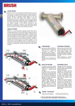
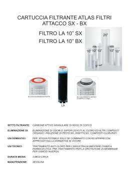
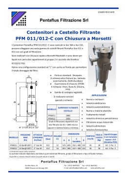
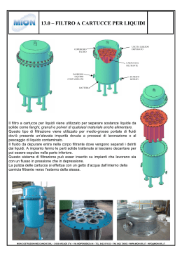
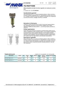
®
Profilo aziendale
Company profile
La salvaguardia dell'ambiente e della vita inizia dal rispetto della risorsa idrica.
A questa finalità abbiamo voluto destinare la nostra esperienza.
SATI S.r.l., nata nel 1980 come società di installazione e servizi, si è specializzata nel
settore della filtrazione e del trattamento di acque primarie, di scarico e di processo,
sviluppando in breve tempo una linea di filtri, che dal 1983 progetta, costruisce e
collauda internamente alla propria struttura.
Safeguarding life and the environment begins when we respect our water resources.
This is the aim we have chosen to focus our experience on.
SATI S.r.l., established in 1980 as an installation and service provider, specialises in the
field of filtering and processing primary water, waste water and water from process
production. In a relatively short space of time we have developed a line of filters entirely
designed, built and tested on our own facilities since 1983.
Treatment.
Il supporto delle moderne tecnologie di modellazione solida e l'impiego di materiali selezionati, quali i
Tecnopolimeri e l'acciaio INOX, conferiscono ai filtri SATI i migliori requisiti di affidabilità e durata nel
tempo, anche quando sottoposti alle più gravose condizioni di esercizio.
Una particolare attenzione é costantemente rivolta alla Ricerca & Sviluppo, investendo nel
rinnovamento delle tecnologie ed avvalendosi della collaborazione di Istituti Universitari e Laboratori
privati di eccellenza.
Support provided by the modern techniques of solid modelling and the use of selected materials - like
Techno-polymers and Stainless Steel - provide SATI filters with the best requisites for dependability and
long-term use, even under the heaviest working conditions.
Research & Development plays a key role in our company philosophy, with attention constantly
focussed on investment and technical innovation, in close collaboration with University Institutes and
private Laboratories of the highest level.
Oggi SATI S.r.l. è in grado di far fronte ad ogni esigenza di mercato, individuando soluzioni concrete e
disponendo di un'ampia gamma di prodotti tecnologicamente avanzati.
La produzione SATI include filtri tradizionali, filtri autopulenti a rete, a cartucce plissettate e a
membrana, coprendo l'intero campo della comune filtrazione, con gradi di separazione da 2.000 fino
a 1 micron, e spingendosi sino alla soglia inferiore di 0,01 micron in ambito di microfiltrazione ed
ultrafiltrazione.
I filtri SATI trovano impiego nelle complesse applicazioni dell'Industria, attraverso i settori più
tradizionali delle Acque Potabili e dell'Irrigazione, sino a soddisfare le esigenze specifiche del settore
Minerario e del trattamento delle Acque di Mare.
Today SATI S.r.l. is in a position to provide a vast range of practical solutions, catering for current and
future market demands, based on a wide range of technological, state-of-the-art products.
The spectrum of SATI products includes traditional filters, self-cleaning screen filters, pleated
cartridge and membrane filters, covering the entire field of basic filtering, with separation degrees
ranging from 2,000 to 1 micron, and reaching the threshold of values less than 0.01 micron in the
fields of micro-filtration and ultra-filtration.
SATI filters are used in complex Industrial applications, ranging from the more traditional sectors of
Drinking Water and Irrigation to successful advanced application, satisfying the specific
requirements in the Mining sector and in Sea Water treatment.
La SATI è presente in ambito internazionale ed opera in regime di Qualità
secondo EN ISO 9001:2000, nel pieno rispetto delle politiche
ambientali.
SATI S.r.l. - ITALY - www.satifiltri.com
SATI enjoys an international market presence and complies with EN ISO
9001:2000 quality standards, fully respecting environmental policies.
SPETTRO DI SEPARAZIONE SEPARATION SPECTRUM
Ranges
IONS
MOLECULES
Aqueous Salt
MACRO MOLECULES
Endotoxin/Pyrogen
Sugar
Materials
Metal
Ion
µm
Units
0,0001
2
0,001
4 6
2
Pollen
2
4 6
Mist
Yeast Cell
Gelatin
0,01
Beach Sand
Granular Activated Carbon
Blue Indigo Dye
Tobacco smoke
4 6
Pin
Point
Milled Flour
Colloidal Silica
Synth
Dye
Human Hair
Bacteria
Virus
Pesticide
MACRO PARTICLES
Red
Blood
Cell
Paint Pigment
Carbon Black
Atomic
Radius
MICRO PARTICLES
Albumin Protein
Coal Dust
0,1
2
4 6
1
2
3
4
5 6
8
10
2
3
4
5 6
8
100
3
2
4
1000
5 6
8
2000
5000
O
A
1
10
100
R.O.
Separation
Process
5
4
10
10
ULTRAFILTRATION
NANOFILTRATION
7
6
10
10
1000
PARTICLE FILTRATION
MICROFILTRATION
BASKET
MINI BASKET
Separators
& Filters
VORTEX
NW BAG
SIMPLEX
BRUSH
Semi-Automatic
Filters
RAPIDJET
VACUUM
TURBONET
AUTOJET
Automatic
Filters
ACQUASPEED
BIG MATIC
ROTOR
VTO
µm
0,0001
2
0,001
4 6
2
4 6
0,01
2
4 6
0,1
2
4 6
1
2
3
4
5 6
8
10
2
3
4
5 6
8
100
2
3
4
5 6
1000
8
O
A
Note
1
10
100
1000
4
10
I campi di lavoro rappresentati nello spettro
di separazione si riferiscono a filtri standard
e possono essere variati su richiesta.
5
10
6
10
Working ranges showned in the separation
spectrum are referred to standard filters and
could be changed on request.
7
10
2000
5000
Industry
Plastica e Tessuti - Plastics & Textile
Torri di raffreddamento
Vasche di raffreddamento
Addolcitori per acque grezze
Acque di lavaggio
Prelavaggio plastici riciclati
Cooling water
Extrusion cooling baths
Raw water softeners
Wash water
Recycle plastic pre-wash
Processi Alimentari - Food & Beverage
Reti di fornitura idrica
Acque di lavaggio
Sistemi di declorazione
Vasche di accumulo
Prefiltrazione
Rimozione odori e sapori
Tunnels di pastorizzazione
Incoming plant water
Wash water
De-chlorinating systems
Water baths
Pre-filtration
Odor & taste removal
Pasteurizing Tunnels
Chimico - Chemical
Reti di fornitura idrica
Torri di raffreddamento
Processi di raffreddamento
Incoming plant water
Cooling towers
Process Cooling
Metallurgico - Steel Industry
Riciclo acque di laminazione
Colate continue
Protezione ugelli
Trattamenti termici
Recupero metalli pesanti
Scale pit water re-use
Continuous casters
Spray nozzle protection
Heat treating
Heavy metal water recovery
Produzione di Energia - Power Generation
Reti di fornitura idrica
Torri di raffreddamento
Processi di raffreddamento
Intake water
Cooling towers
Process Cooling
Petrolchimico - Petrochemicals
Torri di raffreddamento
Acque di processo
Rimozione solidi
Reti di fornitura idrica
Rimozione sostanze tossiche
Iniezione acqua sotterranea
Smaltimento acque iniezione
Cooling water
Process water
Solids removal
Incoming plant water
Toxic removal
Water flood injection
Disposal injection well filtration
Minerario - Mining
Acque di lavaggio
Riutilizzo acque sporche
Rimozione solidi
Bonifica di sostanze tossiche
Wash water
Slurry water re-use
Solids removal
Toxic clean-up
Elettronico - Electronics
Protezione ugelli
Trattamento acque demineralizzate
Recupero metalli pesanti
Spray nozzles protection
Demineralized water treatment
Heavy metal water recovery
Farmaceutico - Pharmaceutical
Reti di fornitura idrica
Torri di raffreddamento
Sistemi di disinfezione UV
Intake water
Cooling towers
UV disinfection systems
Cartario - Pulp & Paper
Acque di lavaggio
Riutilizzo acque di processo
Reti di fornitura idrica
Torri di raffreddamento
Rimozione solidi
Wash water
Process water re-use
Intake water
Cooling towers
Solids removal
Automobilistico - Automotive
Acque di lavaggio
Torri di raffreddamento
Intake water
Cooling towers
Sea Water
Dissalazione - Desalination
Municipal
Acquedottistica - Water Supply
Protezione membrane R.O.
Filtrazione acqua di zavorra
R.O. Membrane protection
Ballast water filtration
Acque di lago e di bacino
Riciclaggio acque
Dams & Lakes water
Water recycling
Potabilizzazione - Drinking Water
Trattamento acque potabili
Separazione sabbia e ghiaia
Drinking water treatment
Sand & grit separation
Acque Reflue - Wastewater
Filtrazione acque di scarico
Rimozione solventi
Separazione sabbia e ghiaia
Filtrazione post-chiarificazione
Irrigation
Final discharge filtration
Solvent removal
Sand & grit separation
Post clarifier filtration
Agricoltura - Agriculture
Filtrazione acque di lago e di fiume
Distribuzione acque irrigue
Sistemi anti-brina
Protezione gocciolatori e aspersori
Irrigazione vigneti e frutteti
Trattamento acque di pozzo
Lake & river water filtration
Irrigation water supply
Frost protection
Drippers & sprinklers protection
Vineyards & orchards irrigation
Well water treatment
Parchi e Giardini - Gardens & Parks
Distribuzione acque irrigue
Protezione gocciolatori e aspersori
Fontane
Irrigation water supply
Drippers & sprinklers protection
Fountains
Campi da Golf - Golf & Turf
Protezione gocciolatori e aspersori
Pools
Drippers & sprinklers protection
Piscine e Impianti sportivi - Pools & Sports
Recupero acque
SATI S.r.l. - ITALY - www.satifiltri.com
Water recycling
BIG MATIC
AUTOJET
ACQUASPEED
VTO
ROTOR
TURBONET
RAPIDJET
VACUUM
BRUSH
NW BAG
SIMPLEX
VORTEX
MINI BASKET
BASKET
APPLICAZIONI CONSIGLIATE
SUGGESTED APPLICATIONS
GAMMA PRODOTTI
PRODUCT RANGE
BASKET
®
Automatic
Filters
5000÷110 µm
Separators
& Filters
®
TURBONET
2000÷25 µm
®
MINI BASKET
3500 µm
®
ROTOR
810÷25 µm
VORTEX
®
1000÷50 µm
®
VTO
810÷25 µm
SIMPLEX
®
2000÷25 µm
ACQUASPEED
®
400÷25 µm
®
NW BAG
200÷1 µm
AUTOJET
®
2000÷25 µm
Semi-Automatic
Filters
®
BRUSH
2000÷25 µm
®
BIG MATIC
53÷1 µm
®
VACUUM
810÷25 µm
RAPIDJET
2000÷25 µm
®
BASKET
FILTRI BASKET
BASKET è un filtro a pulizia manuale con corpo in acciaio inox
dotato di cestello filtrante interno in inox AISI 316 con campi
di filtrazione che vanno da 110 µm a 5 mm. Il filtro viene
fornito con telaio di sostegno, valvola manuale di
svuotamento, valvola automatica di sfiato e manometri. Il
filtro BASKET non ha parti meccaniche in movimento ed è
facilmente apribile per operazioni di pulizia.
BASKET FILTERS
BASKET is a filter with manual cleaning and a stainless steel
body and inside provided with a stainless steel AISI 316
basket with a filtration degrees between 110µµm to 5 mm.
The filter is provided with support frame, manual drain valve,
manual vent valve and pressure gauges. BASKET filter has no
mechanical parts in movement and it is easy to open for
cleaning operations.
3
IN
OUT
1
FILTRAZIONE
FILTERING PROCESS
L’acqua da trattare alimenta il
filtro mediante la connessione di
ingresso (IN), attraversa
l’elemento filtrante (1)
dall’interno verso l’esterno e
defluisce filtrata all’uscita (OUT).
I solidi sospesi restano trattenuti
nella parte interna dell’elemento
filtrante.
Il filtro presenta una valvola di
spurgo (2), normalmente chiusa
durante la filtrazione.
Water enters into the filter
through the inlet connection (IN),
flows through the filter element
(1) from inside towards outside
and flows filtered to the outlet
connection (OUT).
Suspended solids are retained
on the internal surface of the
filter element.
The filter has a drain valve (2),
normally closed during the
filtration process.
SOSTITUZIONE
ELEMENTO FILTRANTE
FILTER ELEMENT
SUBSTITUTION
La sostituzione dell’elemento
filtrante deve essere eseguita
manualmente quando la
dif ferenza di pressione tra
ingr esso e uscita risulta
eccessiva.
Le operazioni di sostituzione
devono avvenire in assenza di
pressione e richiedono lo
smontaggio del coperchio (3) per
l’estrazione dell’elemento
filtrante (1).
The substitution of the filter
element must be manually
executed when the difference of
pressure between inlet and outlet
is excessive.
The substitution operation must
take place in the absence of
pressure and requires the
dismantling of the cover (3) for
the extraction of the filter element
(1).
NORME - STANDARDS
2
Costruzione in conformità alle
direttive 97/23/CE e 98/37/CE.
Manufactured in compliance with
97/23/CE and 98/37/CE directives.
SATI si riserva il diritto di cambiare o apportare modifiche ai prodotti senza preavviso.
SATI reserves the right to change or to bring modifications to the products without prior notice.
SATI S.r.l. - ITALY - www.satifiltri.com
110
5000
DATI TECNICI - TECHNICAL DATA
Area Filtrante Portata Max.
Connessioni
Dimensioni
Connections
Dimensions
Maximum Flow Rate
Screen Area
In/Out
MOD.
Drain
A
B
D
C
CONFIGURAZIONI - EXECUTIONS
Peso
E
F
X
Weight
X
Spazio per smontaggio
Dismantling lenght
(m³/h) (US gpm) (in-mm) (in-mm) (mm) (mm) (mm) (mm) (mm) (mm) (mm) (kg)
(cm²)
(in²)
CS Z 2”/20
2.200
341
40
176
2”
½”
366 206 1070 790 640 420 700
27
CS Z 80/20
2.200
341
80
352
80
½”
406 206 1070 790 640 435 700
32
CS Z 80/35
3.300
512
80
352
80
½”
470 273 1190 860 610 430 700
44
CS Z 100/35
3.300
512
140
616
100
½”
470
273 1190 860 610 430 700
45
CS Z 100/40P
5.400
837
150
660
100
½”
470 273 1470 1140 890 430 1000
57
CS Z 150/40P
5.400
837
300
1320
150
½”
473 273 1480 1150 900 430 1000
59
CS Z 200/40P
5.400
837
400
1760
200
½”
473 273 1580 1195 895 430 1000
73
/20
X
(*) Le portate vengono riferite a filtri con cestello da 110 µm e acqua a 20 °C con NTU < 1.
Flow rates are referred to filters with basket from 110 µm and water with temperature of 20 °C and NTU < 1.
ELEMENTI FILTRANTI - FILTER ELEMENTS
Modello corpo Altezza
Model body
Elementi filtranti disponibili
Cestello (Basket) AISI 316
Gradi di filtrazione disponibili:
(Available filtration degrees)
110 - 200 - 400 - 1000 - 2000- 3500 - 5000
Ø interno
Height
Internal
(mm)
(mm)
KC/20
540
145
KC/35
580
218
KC/40P
880
218
/35 e /40
X
PERDITE DI CARICO - HEAD PRESSURE LOSS
(psi) (bar)
Ø 2”
DN80 DN100
CARATTERISTICHE - FEATURES
DN150
Campo di filtrazione
Filtration range
Pressione massima di esercizio
Maximum working pressure
Temperatura massima del fluido
Fluid maximum temperature
Salinità e Acidità
Salinity & acidity
Connessioni
End connections
Trattamento superficiale
Surface finishing
DN200
1.0
10.0
5.0
0.3
Con acqua pulita e rete standard.
With clean water and standard screen.
0.1
5.000 ÷ 110 µm
10,0 bar (145,0 psi)
60°C (140°F)
< 10.000 ppm TDS
PH 3÷9
ISO PN16/10 - BSP
ANSI150 - NPT
Decapaggio (etching)
1.0
MATERIALI - MATERIALS
0.01
2
8
6
4
10
20
8
30
10
20
60
80
100
40
200
60
300
100
200
600
1.000
400
600
2.000 3.000
1.000
6.000
(m³/h)
(US gpm)
AISI 304 / 316
Carcassa esterna
Filter housing
Elemento di sostegno AISI 316
Screen support
Cestello (Basket) AISI 316
Elemento filtrante
Screen
Epdm
Guarnizioni
Seals
MINI BASKET
FILTRI MINI BASKET
MINI BASKET è un filtro a pulizia manuale con corpo in acciaio
inox dotato di cestello filtrante interno in inox AISI 316. Il filtro
MINI BASKET non ha parti meccaniche in movimento, è
facilmente apribile per operazioni di pulizia e viene fornito con
valvola manuale di svuotamento. Può essere utilizzato a
protezione di pompe di circolazione dell'acqua, per evitare
l'ingresso di corpi estranei che potrebbero danneggiare la
girante delle pompe e l'impianto.
MINI BASKET FILTERS
MINI BASKET is a filter with manual cleaning and with
stainless steel body. It is provided with a stainless steel AISI
316 internal filtrating basket. The MINI BASKET filter has no
mechanical parts in movement, it is easy to open for cleaning
and it is provided with a manual drain valve. It can be used as
a protection for the water circulation pumps, to prevent the
entrance of foreign particles which could damage the pump
impeller and the plant.
3
IN
OUT
1
2
FILTRAZIONE
FILTERING PROCESS
L’acqua da trattare alimenta il
filtro mediante la connessione di
ingresso (IN), attraversa
l’elemento filtrante (1)
dall’interno verso l’esterno e
defluisce filtrata all’uscita (OUT).
I solidi sospesi restano trattenuti
nella parte interna dell’elemento
filtrante.
Il filtro presenta una valvola di
spurgo (2), normalmente chiusa
durante la filtrazione.
Water enters into the filter
through the inlet connection (IN),
flows through the filter element
(1) from inside towards outside
and flows filtered to the outlet
connection (OUT).
Suspended solids are retained
on the internal surface of the
filter element.
The filter has a drain valve (2),
normally closed during the
filtration process.
SOSTITUZIONE
ELEMENTO FILTRANTE
FILTER ELEMENT
SUBSTITUTION
La sostituzione dell’elemento
filtrante deve essere eseguita
manualmente quando la
dif ferenza di pressione tra
ingr esso e uscita risulta
eccessiva.
Le operazioni di sostituzione
devono avvenire in assenza di
pressione e richiedono lo
smontaggio del coperchio (3) per
l’estrazione dell’elemento
filtrante (1).
The substitution of the filter
element must be manually
executed when the difference of
pressure between inlet and outlet
is excessive.
The substitution operation must
take place in the absence of
pressure and requires the
dismantling of the cover (3) for
the extraction of the filter element
(1).
NORME - STANDARDS
Costruzione in conformità alle
direttive 97/23/CE e 98/37/CE.
Manufactured in compliance with
97/23/CE and 98/37/CE directives.
SATI si riserva il diritto di cambiare o apportare modifiche ai prodotti senza preavviso.
SATI reserves the right to change or to bring modifications to the products without prior notice.
SATI S.r.l. - ITALY - www.satifiltri.com
3500
DATI TECNICI - TECHNICAL DATA
Area Filtrante Portata Max.
Screen Area
Maximum Flow Rate
Connessioni
Dimensioni
Connections
Dimensions
In/Out
MOD.
Drain
A
B
C
D
CONFIGURAZIONI - EXECUTIONS
Peso
E
X
X
Weight
Spazio per smontaggio
Dismantling lenght
(m³/h) (US gpm) (in-mm) (in-mm) (mm) (mm) (mm) (mm) (mm) (mm) (kg)
(cm²)
(in²)
MBK 80
1.900
295
130
572
80
½”
433 273 357 156 156 400
23
MBK 100
1.900
295
210
924
100
½”
433 273 357 156 156 400
26
MBK 125
1.900
295
300
1.320
125
½”
433 273 357 156 156 400
28
MBK 150
1.900
295
380
1.672
150
½”
433 273
32
357 156 156 400
Flow rates are referred to filters with basket from 3500 µm and water with temperature of 20 °C and NTU < 1.
ELEMENTI FILTRANTI - FILTER ELEMENTS
Model body
Cestello (Basket) AISI 316
Gradi di filtrazione disponibili:
(Available filtration degrees)
3500
Internal
(mm)
(mm)
290
218
MBK
PERDITE DI CARICO - HEAD PRESSURE LOSS
(psi) (bar)
OUT
E
B
A
Ø interno
Height
Elementi filtranti disponibili
IN
C
D
(*) Le portate vengono riferite a filtri con cestello da 3500 µm e acqua a 20 °C con NTU < 1.
Modello corpo Altezza
x
CARATTERISTICHE - FEATURES
Campo di filtrazione
Filtration range
Pressione massima di esercizio
Maximum working pressure
Temperatura massima del fluido
Fluid maximum temperature
Salinità e Acidità
Salinity & acidity
Connessioni
End connections
Trattamento superficiale
Surface finishing
DN80 DN100 DN125 DN150
1.0
10.0
5.0
0.3
3.500 µm
6,0 bar (87,0 psi)
60°C (140°F)
< 10.000 ppm TDS
PH 3÷9
ISO PN16/10
Decapaggio (etching)
0.1
1.0
MATERIALI - MATERIALS
Con acqua pulita e rete standard.
With clean water and standard screen.
0.01
10
20
60
80
100
40
200
60
300
100
200
600
1.000
400
600
2.000 3.000
1.000 (m³/h)
(US gpm)
AISI 304 / 316
Carcassa esterna
Filter housing
Elemento di sostegno AISI 316
Screen support
Cestello (Basket) AISI 316
Elemento filtrante
Screen
Epdm
Guarnizioni
Seals
VORTEX
SEPARATORI VORTEX
VORTEX SEPARATORS
VORTEX è un filtro separatore centrifugo con
corpo in acciaio inox e scarico manuale di
fondo. E’ particolarmente indicato per trattare
acque contenenti sabbie e/o solidi sospesi
con peso specifico superiore a quello
dell’acqua (Ps 1). Il filtro è in grado di
rimuovere fino al 99% di sabbie e/o solidi
sospesi con dimensioni superiori a 75 µm e
fino al 65% con dimensioni 50 µm. E’ stato
progettato per contenere al massimo le
perdite di carico pur mantenendo un’ottima
efficienza di separazione. Il filtro VORTEX
lavora in continuo, non contiene elementi
filtranti o parti in movimento, è ispezionabile e
può essere corredato di dispositivo per
scarico automatico.
VORTEX is a centrifugal separating filter with a
stainless steel body and a manual drain at the
bottom. It is particularly indicated to treat
water containing sands and/or suspended
solids of a specific gravity superior to the
water (P 1). The filter is able to remove until
99% of sands and/or suspended solids with
dimensions bigger then 75µµm and until the
65% with dimensions bigger then 50µµm. It
has been designed to prevent at its best, the
drain losses but maintaining the best
separating ef ficiency. VORTEX works
continuously, it does not contain filtrating
elements or parts in movements, it can be
inspected and can be provided of an
automatic drain.
OUT
FILTRAZIONE
IN
1
2
3
La connessione di alimentazione (2) é
disegnata per incrementare la velocità del
flusso idrico in ingresso al separatore e
tale da determinare un moto vorticoso
discendente all’interno della carcassa
(1).
La progressiva accelerazione creata dallo
speciale cono (3) interno, genera la forza
centrifuga necessaria per una efficace
separazione dei solidi indesiderati.
L’acqua filtrata risale centralmente verso
la connessione di uscita, mentre I solidi
separati precipitano nel serbatoio di
raccolta sotto al deflettore (4), per poi
essere scaricati all’esterno (5).
FILTERING PROCESS
4
5
The water supply connection (2) has been
designed to speed up the main flow at the
inlet of the filter itself, in order to favour a
descending water vortex inside the
housing (1).
The progressive acceleration, within the
special internal cone (3), creates the
centrifugal force needed for the best
separation of undesired solids.
The filtered water re-emerges centrally
through the “OUT” connection, while
separates solids drop in the tank
underneath the deflector (4)and are
drained outside (5).
NORME - STANDARDS
Costruzione in conformità alle
direttive 97/23/CE e 98/37/CE.
Manufactured in compliance with
97/23/CE and 98/37/CE directives.
SATI si riserva il diritto di cambiare o apportare modifiche ai prodotti senza preavviso.
SATI reserves the right to change or to bring modifications to the products without prior notice.
SATI S.r.l. - ITALY - www.satifiltri.com
50
1000
DATI TECNICI - TECHNICAL DATA
Portata Min.
Portata Max.
Connessioni
Dimensioni
Peso
Connections
Dimensions
Weight
Minimum Flow Rate Maximum Flow Rate
MOD.
In/Out
Drain
A
B
D
E
X
C
(m³/h) (US gpm) (in-mm) (in-mm) (mm) (mm) (mm) (mm) (mm) (mm)
(kg)
(m³/h)
(US gpm)
VX ¾”
2
9
4
18
¾”
½”
180
525
155 110
30
220
9
VX 1”
4
18
9
40
1”
¾”
205
860
155 120
40
220
15
VX 1”½
8
35
18
79
1”½
¾”
260 1060 195 160
45
220
23
VX 2”
15
66
30
132
2”
¾”
300 1200 205 190
55
220
30
VX 3”
25
110
60
264
3”
¾”
370 1600 265 230
65
220
51
VX 100
54
238
105
462
100
1”
470 1860 315 300
80
250
85
VX 150
95
418
190
836
150
2”
590 2150 335 400
80
300
105
180
792
300
1320
150
2”
630 2300 505 405 125 300
130
VX 150P
A
EFFICIENZA DI SEPARAZIONE
SEPARATION EFFICIENCY
D
99 %
OUT
C
IN
(Efficiency %)
65 %
Vista dall’alto
Top View
B
E
x
25
75
50
100
PERDITE DI CARICO - HEAD PRESSURE LOSS
10.0
Ø 1”½
50.0
DN100
Ø 1”
DN150
Ø 2”
Ø ¾”
1
Spazio per smontaggio
Dismantling lenght
Campo di filtrazione
Filtration range
Pressione massima di esercizio
Maximum working pressure
Temperatura massima del fluido
Fluid maximum temperature
Salinità e Acidità
Salinity & acidity
Connessioni
End connections
Trattamento superficiale
Surface finishing
10
Ø 3”
X
CARATTERISTICHE - FEATURES
(psi) (bar)
3
DRAIN
( Particle size µm )
150
1.000 ÷ 50 µm
10,0 bar (145,0 psi)
60°C (140°F)
< 10.000 ppm TDS
PH 3÷9
ISO PN16/10 - BSP
ANSI150 - NPT
Decapaggio (etching)
DN150P
10.0
MATERIALI - MATERIALS
0.1
2
8
6
4
10
20
8
30
10
20
60
80
100
40
200
60
300
100
200
600
1.000
400
600
2.000 3.000
1.000
6.000
(m³/h)
(US gpm)
Carcassa esterna
Filter housing
Cono acceleratore
Accelerator cone
AISI 304 / 316
Deflettore
Deflector
Guarnizioni
Seals
AISI 304 / 316
Plastic
Epdm
SIMPLEX
FILTRI SIMPLEX
SIMPLEX è un filtro a rete a pulizia manuale con corpo in
acciaio inox. La cartuccia filtrante interna è composta da una
rete tubolare inox AISI 316 sulla quale può essere inserito un
tessuto filtrante in poliestere (PES) oppure da una rete
filtrante inox AISI 316 doppio strato (REPS). I campi di
filtrazione vanno da 25 a 2000 µm, non ha parti meccaniche
in movimento e per la pulizia della cartuccia si dovrà
intervenire togliendo il coperchio di fondo del filtro che viene
fornito con valvola manuale di scarico e manometri.
SIMPLEX FILTERS
SIMPLEX is a manual cleaning screen filter with stainless
steel body. The internal filtrating cartridge consists of an AISI
316 stainless steel tubular screen on which can be inserted a
polyester filtrating mesh (PES) or a stainless steel AISI 316
filtering double screen (REPS). The filtration range is between
25 to 2000 µm. To clean the cartridge it is necessary to
remove the cover at the bottom of the filter which is provided
with drain manual valve and pressure gauges.
OUT
IN
1
3
FILTRAZIONE
FILTERING PROCESS
L’acqua da trattare alimenta il
filtro mediante la connessione di
ingresso (IN), attraversa
l’elemento filtrante (1)
dall’interno verso l’esterno e
defluisce filtrata all’uscita (OUT).
I solidi sospesi restano trattenuti
nella parte interna dell’elemento
filtrante.
Il filtro dispone di una
connessione (2) per valvola di
spurgo, normalmente chiusa
durante la filtrazione.
Water enters into the filter from
the inlet connection (IN), flows
into the filter element (1) from
inside towards outside, exits
from the outlet connection (OUT).
Suspended solids are caught by
the internal surface of the filter
element.
The filter is a drain valve
connection (2), normally closed
during filtering process.
2
1
PULIZIA
CLEANING
La pulizia del filtro deve essere
eseguita manualmente quando la
dif ferenza di pressione tra
ingr esso e uscita risulta
eccessiva.
Le operazioni di pulizia devono
avvenire in assenza di pressione
e richiedono lo smontaggio del
coperchio (3) per l’estrazione
dell’elemento filtrante (1) e la
rimozione dei solidi sospesi in
esso trattenuti.
Cleaning of the filter is carried out
manually when the differential
pressure between inlet and outlet
exceeds a given value.
The cleaning operation, to be
carried out only with
depressurized filter housing,
require removing the cover (3),
pulling out the filter element (1)
and its manual cleaning.
NORME - STANDARDS
Costruzione in conformità alle
direttive 97/23/CE e 98/37/CE.
3
SATI S.r.l. - ITALY - www.satifiltri.com
Manufactured in compliance with
97/23/CE and 98/37/CE directives.
SATI si riserva il diritto di cambiare o apportare modifiche ai prodotti senza preavviso.
SATI reserves the right to change or to bring modifications to the products without prior notice.
25
2000
DATI TECNICI - TECHNICAL DATA
Area Filtrante Portata Max.
Connessioni
Dimensioni
Peso
Connections
Dimensions
Weight
Maximum Flow Rate
Screen Area
In/Out
MOD.
Drain
A
B
C
D
CONFIGURAZIONI - EXECUTIONS
X
(m³/h) (US gpm) (in-mm) (in-mm) (mm) (mm) (mm) (mm) (mm)
(in²)
SI L 2”/10A
1.500
233
40
176
2”
1”
320 500 295 203 350
14
SI L 3”/10A
1.500
233
80
352
3”
1”
320 500 295 203 350
14
SI L 100/10A
1.500
233
100
440
100
1”
320 550 345 203 350
20
SI L 3”/20
2.200
341
80
352
3”
1”
320 650 295 203 500
15
SI L 100/20
2.200
341
130
572
100
1”
320 700 345 203 500
22
SI L 100/35
3.300
512
140
616
100
1”
390 705 345 235 500
30
SI L 150/35
3.300
512
250
1.101
150
1”
390 705 345 235 500
36
SI L 150/40P
5.400
837
300
1.321
150
1”
390 1010 345 235 800
45
SI O 2”/10A
1.500
233
40
176
2”
1”
990 325 450 215 500
20
SI O 3”/10A
1.500
233
80
352
3”
1”
990 325 450 215 500
20
SI O 100/10A
1.500
233
100
440
100
1”
990 325 450 215 500
24
SI O 100/20
2.200
341
130
572
100
1”
990 325 450 215 500
25
SI O 100/35
3.300
512
140
616
100
1”
1450 390 640 245 800
57
SI O 150/35
3.300
512
250
1.101
150
1”
1450 390 640 245 800
59
SI O 150/40P
5.400
837
300
1.321
150
1”
1450 390 640 245 800
60
SI O 200/40P
5.400
837
400
1.760
200
1”
1450 430 640 285 800
64
SI Y 1”/5
600
93
10
44
1”
1”
430 285 280 140 300
5
SI Y 1”½/5
600
93
15
66
1”½
1”
430 300 275 140 300
7
SI Y 2”/10A
1.500
233
40
176
2”
1”
500 360 400 225 350
14
SI Y 3”/10A
1.500
233
80
352
3”
1”
520 370
450 225 350
15
SI Y 100/10A
1.500
233
100
440
100
1”
565 440 550 225 350
20
SI Y 3”/20
2.200
341
80
352
3”
1”
630 480 450 225 500
24
SI Y 100/20
2.200
341
130
572
100
1”
670 540 550 225 500
38
SI Y 100/35
3.300
512
140
616
100
1”
670 570 600 291 500
40
SI Y 150/35
3.300
512
250
1.101
150
1”
755 600 745
291 500
45
SI Y 150/40P
5.400
837
300
1.321
150
1”
960 820 745
291 800
45
Spazio per smontaggio
Dismantling lenght
X
(kg)
(cm²)
L
A
D
x
B
OUT
C
DRAIN
IN
O
A
x
DRAIN
B D
x
C
OUT
IN
Y
A
C
OUT
IN
B
x
DRAIN
(*) Le portate vengono riferite a filtri con rete filtrante da 120 µm e acqua a 20 °C con NTU < 1.
D
Flow rates are referred to filters with filtrating mesh from 120 µm and water with temperature of 20 °C and NTU < 1.
PERDITE DI CARICO - HEAD PRESSURE LOSS
(psi) (bar)
Ø 1”
Ø 1”½ Ø 2”
Ø 3” DN100
DN150
CARATTERISTICHE - FEATURES
DN200
Campo di filtrazione
Filtration range
Pressione massima di esercizio
Maximum working pressure
Temperatura massima del fluido
Fluid maximum temperature
Salinità e Acidità
Salinity & acidity
Connessioni
End connections
Trattamento superficiale
Surface finishing
1.0
Con acqua pulita e rete standard.
With clean water and standard screen.
10.0
5.0
0.3
0.1
2.000 ÷ 25 µm
10,0 bar (145,0 psi)
60°C (140°F)
< 10.000 ppm TDS
PH 3÷9
ISO PN16/10 - BSP
ANSI150 - NPT
Decapaggio (etching)
1.0
MATERIALI - MATERIALS
0.01
2
8
6
4
10
20
8
30
10
20
60
80
100
40
200
60
300
100
200
600
1.000
400
600
2.000 3.000
1.000
6.000
(m³/h)
(US gpm)
Carcassa esterna AISI 304 / 316
Filter housing
Elemento di sostegno AISI 316
Screen support
Elemento filtrante PES / REPS - std. 120 µm
Screen
Epdm
Guarnizioni
Seals
BRUSH
FILTRI BRUSH
BRUSH è un filtro a rete a pulizia semiautomatica con corpo in
acciaio inox. La cartuccia filtrante interna è composta da una
rete tubolare inox AISI 316 sulla quale può essere inserito un
tessuto filtrante in poliestere (PES) oppure da una rete
filtrante inox AISI 316 doppio strato (REPS). I campi di
filtrazione vanno da 25 a 2000 µm, la cartuccia viene pulita
da spazzole azionabili manualmente da un leveraggio esterno
ed il filtro viene fornito di valvole manuali e manometri. Per il
suo migliore impiego il filtro BRUSH necessita di una
pressione in ingresso di almeno 2 bar assicurando ridotti
tempi e consumi d’acqua in fase di pulizia, durante la quale il
flusso in uscita dovrà essere manualmente interrotto.
BRUSH FILTERS
BRUSH is a semi-automatic cleaning screen filter with a
stainless steel body. he internal filtrating cartridge consists of
an AISI 316 stainless steel tubular screen on which can be
inserted a polyester filtrating mesh (PES) or a stainless steel
AISI 316 filtering double screen (REPS). The filtration range is
from 25 to 2000µµm. The cartridge is cleaned by a series of
brushes manually operated by an external handle. The filter is
supplied with manual valves and pressure gauges. For its
best performance the BRUSH needs an inlet pressure of at
least 2 bars, ensuring short times and low water consumption
during the cleaning cycle. During this phase the outlet flux is
stopped.
OUT
IN
1
DRAIN
2
4
IN
OUT
5
1
3
DRAIN
2
FILTRAZIONE
FILTERING PROCESS
L’acqua da trattare alimenta il
filtro mediante la connessione di
ingresso (IN), attraversa
l’elemento filtrante (1)
dall’interno verso l’esterno e
defluisce filtrata all’uscita (OUT).
I solidi sospesi restano trattenuti
nella parte interna dell’elemento
filtrante.
Durante la fase di filtrazione la
connessione di scarico (2) resta
chiusa.
Water enters into the filter from
the inlet connection (IN), flows
into the filter element (1) from
inside towards outside, exits
from the outlet connection (OUT).
Suspended solids are caught by
the internal surface of the filter
element.
Drain connection (2) remains
closed during filtration process.
CICLO DI PULIZIA
CLEANING CYCLE
La pulizia del filtro deve essere
eseguita manualmente quando la
dif ferenza di pressione tra
ingr esso e uscita risulta
eccessiva.
La pulizia richiede l’interruzione
del flusso in linea (chiusura della
connessione di uscita [OUT]), al
fine di generare equipressione
all’interno del filtro e favorire il
distacco dei solidi dalla parete
dell’elemento filtrante (1).
L’apertura dello scarico (2) e la
rotazione delle spazzole (4)
operata mediante la manovella
(3), consentono di rimuovere e
scaricare all’esterno i solidi
trattenuti, senza necessità di
smontaggio del coperchio (5) del
filtro .
Cleaning of the filter is carried out
manually when the differential
pressure between inlet and outlet
exceeds a given value.
Cleaning process requires
stopping the downstream flow
(closure of the connection [OUT])
in order to generate static
pressure inside the filter housing
and favour the removal of the
debris from the surface of the
filter element.
Opening of the drain connection
(2) and the manual activation
(rotation) of the brushes (4) by
means of the cranck (3) allow to
remove and discharge outside
the suspended solids. Cleaning
process is done without need to
disassemble the cover (5) of the
filter housing .
NORME - STANDARDS
Costruzione in conformità alle
direttive 97/23/CE e 98/37/CE.
Manufactured in compliance with
97/23/CE and 98/37/CE directives.
SATI si riserva il diritto di cambiare o apportare modifiche ai prodotti senza preavviso.
SATI reserves the right to change or to bring modifications to the products without prior notice.
SATI S.r.l. - ITALY - www.satifiltri.com
25
2000
DATI TECNICI - TECHNICAL DATA
Area Filtrante Portata Max.
Connessioni
Dimensioni
Peso
Connections
Dimensions
Weight
Maximum Flow Rate
Screen Area
In/Out
MOD.
Drain
A
B
C
D
CONFIGURAZIONI - EXECUTIONS
X
X
(m³/h) (US gpm) (in-mm) (in-mm) (mm) (mm) (mm) (mm) (mm)
(kg)
(cm²)
(in²)
BR Y 2”/10A
1.500
233
40
176
2”
1”½
640 470 445 130 350
17
BR Y 3”/10A
1.500
233
80
352
3”
1”½
670 485 510
18
130 350
Spazio per smontaggio
Dismantling lenght
Y
A
C
BR Y 3”/20
2.200
341
80
352
3”
1”½
780 595 510 120 500
22
BR Y 100/20
2.200
341
130
572
100
1”½
820 660 600 130 500
27
BR Y 100/35
3.300
512
140
616
100
1”½
820 660 650 130 500
42
BR Y 150/35
3.300
512
250
1.100
150
1”½
890 690 800 130 500
54
IN
BR Y 150/40P
5.400
837
300
1.320
150
2”
1140 900 800 170 800
61
B
OUT
x
(*) Le portate vengono riferite a filtri con rete filtrante da 120 µm e acqua a 20 °C con NTU < 1.
Flow rates are referred to filters with filtrating mesh from 120 µm and water with temperature of 20 °C and NTU < 1.
D
DRAIN
PERDITE DI CARICO - HEAD PRESSURE LOSS
(psi) (bar)
Ø 2”
Ø 3” DN100
CARATTERISTICHE - FEATURES
Campo di filtrazione
Filtration range
Pressione massima di esercizio
Maximum working pressure
Pressione minima di pulizia
Minimum cleaning pressure
Temperatura massima del fluido
Fluid maximum temperature
Salinità e Acidità
Salinity & acidity
Connessioni
End connections
Trattamento superficiale
Surface finishing
DN150
1.0
10.0
5.0
0.3
Con acqua pulita e rete standard.
With clean water and standard screen.
0.1
1.0
2.000 ÷ 25 µm
10,0 bar (145,0 psi)
1,0 bar (14,50 psi)
60°C (140°F)
< 10.000 ppm TDS
PH 3÷9
ISO PN16/10 - BSP
ANSI150 - NPT
Decapaggio (etching)
MATERIALI - MATERIALS
0.01
2
8
6
4
10
20
8
30
10
20
60
80
100
40
200
60
300
100
200
600
1.000
400
600
2.000 3.000
1.000
6.000
(m³/h)
(US gpm)
Carcassa esterna AISI 304 / 316
Filter housing
Elemento di sostegno AISI 316
Screen support
Elemento filtrante PES / REPS - std. 120 µm
Screen
Epdm
Guarnizioni
Seals
TURBONET
FILTRI TURBONET
TURBONET è un filtro a rete a pulizia automatica con corpo in
acciaio inox. La cartuccia filtrante interna è composta da una
rete tubolare inox AISI 316 sulla quale può essere inserito un
tessuto filtrante in poliestere (PES) oppure da una rete
filtrante inox AISI 316 doppio strato (REPS). I campi di
filtrazione vanno da 25 a 2000 µm, la cartuccia viene pulita
da spazzole poste su di un albero rotante azionato da un
motore elettrico a 24 Vcc. Il filtro viene fornito e cablato con:
gruppo di automazione, valvole e manometri. Per il suo
migliore impiego il filtro TURBONET necessita di una
pressione in ingresso di almeno 2 bar assicurando ridotti
tempi e consumi d’acqua in fase di pulizia, durante la quale il
flusso in uscita viene automaticamente interrotto.
TURBONET FILTERS
TURBONET is a self-cleaning screen filter with a stainless
steel body. he internal filtrating cartridge consists of an AISI
316 stainless steel tubular screen on which can be inserted a
polyester filtrating mesh (PES) or a stainless steel AISI 316
filtering double screen (REPS). The filtration range is from 25
to 2000µµm. The cartridge is cleaned by brushes mounted on
a rotating shaft and moved by a 24 Vcc electric motor. The
filter is supplied and already wired with: automation group,
valves and pressure gauges. For its best performance the
TURBONET needs an inlet pressure of at least 2 bars,
ensuring short times and low water consumption during the
cleaning cycle. During this phase the outlet flux is
automatically stopped.
OUT
IN
1
DRAIN
2
4
IN
OUT
5
3
1
FILTRAZIONE
FILTERING PROCESS
L’acqua da trattare alimenta il
filtro mediante la connessione di
ingresso (IN), attraversa
l’elemento filtrante (1)
dall’interno verso l’esterno e
defluisce filtrata all’uscita (OUT).
I solidi sospesi restano trattenuti
nella parte interna dell’elemento
filtrante.
Durante la fase di filtrazione la
connessione di scarico (2) resta
chiusa e le spazzole (4) restano
ferme.
Water enters into the filter from
the inlet connection (IN), flows
into the filter element (1) from
inside towards outside, exits
from the outlet connection (OUT).
Suspended solids are caught by
the internal surface of the filter
element.
During the filtration, drain
connection (2) remains closed
and brushes are in stand-by .
CICLO DI PULIZIA
CLEANING CYCLE
La pulizia del filtro viene eseguita
quando la differenza di pressione
tra ingresso e uscita risulta
eccessiva.
Il ciclo di pulizia richiede
l’interruzione del flusso in linea
(chiusura della connessione di
uscita [OUT]), al fine di generare
equipressione all’interno del
filtro e favorire il distacco dei
solidi dalla parete dell’elemento
filtrante (1). L’aper tura dello
scarico (2) e la rotazione delle
spazzole (4) vengono operate
automaticamente, consentendo
di rimuovere e di scaricare
all’esterno i solidi trattenuti,
senza necessità di smontaggio
del coperchio del filtro (5).
La rotazione delle spazzole è
impartita da un motore elettrico
[TUM] (3).
Gestione e programmazione del
ciclo di pulizia richiedono
l’installazione di un
programmatore elettronico SATI.
Cleaning of the filter is carried out
when the differential pressure
between inlet and outlet exceeds
a given value.
Cleaning process requires
stopping the downstream flow
(closure of the connection [OUT])
in order to generate static
pressure inside the filter housing
and favour removal of the solids
from the surface of the filter
element (1).
Opening of the drain connection
(2) and the manual activation
(rotation) of the brushes (4) allow
to remove and discharge outside
the suspended solids, without
need to remove the cover (5) of
the filter housing.
Rotational movement of the set
of brushes is automatically
operated by means of an electric
motor [TUM] (3).
Management of the cleaning
cycle require the installation of an
electronic controller by SATI.
NORME - STANDARDS
Costruzione in conformità alle
direttive 97/23/CE e 98/37/CE.
Manufactured in compliance with
97/23/CE and 98/37/CE directives.
DRAIN
2
SATI S.r.l. - ITALY - www.satifiltri.com
SATI si riserva il diritto di cambiare o apportare modifiche ai prodotti senza preavviso.
SATI reserves the right to change or to bring modifications to the products without prior notice.
25
2000
DATI TECNICI - TECHNICAL DATA
Area Filtrante Portata Max.
Screen Area
Connessioni
Dimensioni
Peso
Connections
Dimensions
Weight
Maximum Flow Rate
In/Out
MOD.
Drain
A
B
D
C
CONFIGURAZIONI - EXECUTIONS
X
X
(m³/h) (US gpm) (in-mm) (in-mm) (mm) (mm) (mm) (mm) (mm)
Spazio per smontaggio
Dismantling lenght
(kg)
(cm²)
(in²)
TUM Y 2”/10A
1.500
233
40
176
2”
1”
450 700 550 165 350
28
TUM Y 3”/10A
1.500
233
80
352
3”
1”
500 720 660 165 350
30
TUM Y 100/20
2.200
341
130
572
100
1”½
650 840 850 165 500
52
TUM Y 100/35
3.300
512
140
616
100
1”½
710 870 900 165 500
60
TUM Y 150/35
3.300
512
250
1.101
150
1”½
750 890 1095 165 500
90
TUM Y 150/40P
5.400
837
300
1.321
150
2”
970 1100 1095 190 800
99
M
C
IN
OUT
B
(*) Le portate vengono riferite a filtri con rete filtrante da 120 µm e acqua a 20 °C con NTU < 1.
Flow rates are referred to filters with filtrating mesh from 120 µm and water with temperature of 20 °C and NTU < 1.
D
DRAIN
PERDITE DI CARICO - HEAD PRESSURE LOSS
(psi) (bar)
Ø 2”
Ø 3” DN100
x
A
CARATTERISTICHE - FEATURES
Campo di filtrazione
Filtration range
Pressione massima di esercizio
Maximum working pressure
Pressione minima di pulizia
Minimum cleaning pressure
Temperatura massima del fluido
Fluid maximum temperature
Salinità e Acidità
Salinity & acidity
Connessioni
End connections
Trattamento superficiale
Surface finishing
DN150
1.0
10.0
5.0
0.3
Con acqua pulita e rete standard.
With clean water and standard screen.
0.1
1.0
2.000 ÷ 25 µm
10,0 bar (145,0 psi)
3,0 bar (43,5 psi)
60°C (140°F)
< 10.000 ppm TDS
PH 3÷9
ISO PN16/10 - BSP
ANSI150 - NPT
Decapaggio (etching)
MATERIALI - MATERIALS
0.01
2
8
6
4
10
20
8
30
10
20
60
80
100
40
200
60
300
100
200
600
1.000
400
600
2.000 3.000
1.000
6.000
(m³/h)
(US gpm)
AISI 304 / 316
Carcassa esterna
Filter housing
Elemento di sostegno AISI 316
Screen support
Elemento filtrante PES / REPS - std. 120 µm
Screen
Epdm
Guarnizioni
Seals
VACUUM
FILTRI VACUUM
VACUUM è un filtro a rete a pulizia semiautomatica con corpo
in acciaio inox. La cartuccia filtrante interna tipo “sandwich” è
composta da un tessuto filtrante in poliestere o acciaio inox
AISI 316 inglobato tra due reti tubolari inox AISI 316. I campi
di filtrazione vanno da 25 a 810 µm e la cartuccia viene pulita
da una serie di pattini aspiranti azionabili manualmente da un
leveraggio esterno. Il filtro viene fornito di valvole manuali e
manometri. Per il suo migliore impiego il filtro VACUUM
necessita di una pressione in ingresso di almeno 3 bar
assicurando ridotti tempi e consumi d’acqua in fase di pulizia,
durante la quale il filtro continua a erogare permeato.
VACUUM FILTERS
VACUUM is a semi-automatic cleaning screen filter. The
"sandwich" type internal cartridge consists of a polyester or
stainless steel AISI 316 filtrating mesh closed between two
stainless steel AISI 316 tubular screen. The filtration range is
from 25 to 810µµm. The cartridge is cleaned by a series of
suction pads manually moved by an external handle. The filter
is supplied with manual valves and pressure gauges. For its
best performance the VACUUM needs an inlet pressure of at
least 3 bars, ensuring short times and low water consumption
during the cleaning cycle. During this phase the filter
continues to produce permeate.
OUT
IN
1
FILTRAZIONE
FILTERING PROCESS
L’acqua da trattare alimenta il
filtro mediante la connessione di
ingresso (IN), attraversa
l’elemento filtrante (1)
dall’interno verso l’esterno e
defluisce filtrata all’uscita (OUT).
I solidi sospesi restano trattenuti
nella parte interna dell’elemento
filtrante.
Durante la fase di filtrazione la
connessione di scarico (2) resta
chiusa.
Water enters into the filter from
the inlet connection (IN), flows
into the filter element (1) from
inside towards outside, exits
from the outlet connection (OUT).
Suspended solids are caught by
the internal surface of the filter
element.
Drain connection (2) remains
closed during filtering process.
CICLO DI PULIZIA
CLEANING CYCLE
La pulizia del filtro deve essere
eseguita manualmente quando la
dif ferenza di pressione tra
ingr esso e uscita risulta
eccessiva.
La pulizia avviene senza
l’interruzione del flusso .
L’apertura dello scarico (2) e la
rotazione dei pattini (4) operata
mediante la manovella (3),
consentono di rimuovere e
scaricare all’esterno i solidi
trattenuti, senza necessità di
smontaggio del coperchio (5) del
filtro.
Cleaning of the filter is carried out
manually when the differential
pressure between inlet and outlet
exceeds a given value.
Cleaning process activates
without stopping the flow.
Opening of the drain connection
(2) and the manual activation
(rotation) of the flat suction pads
(4) by means of the cranck (3)
allow to remove and discharge
outside the suspended solids.
Cleaning
process is done
without need to disassemble the
cover (5) of the filter housing.
DRAIN
2
OUT
IN
5
4
3
DRAIN
NORME - STANDARDS
Costruzione in conformità alle
direttive 97/23/CE e 98/37/CE.
Manufactured in compliance with
97/23/CE and 98/37/CE directives.
SATI si riserva il diritto di cambiare o apportare modifiche ai prodotti senza preavviso.
SATI reserves the right to change or to bring modifications to the products without prior notice.
SATI S.r.l. - ITALY - www.satifiltri.com
25
810
DATI TECNICI - TECHNICAL DATA
Area Filtrante Portata Max.
Screen Area
Connessioni
Dimensioni
Peso
Connections
Dimensions
Weight
Maximum Flow Rate
In/Out
MOD.
Drain
A
B
D
C
X
X
(m³/h) (US gpm) (in-mm) (in-mm) (mm) (mm) (mm) (mm) (mm)
(in²)
VA L 2”/10A
1.500
233
40
176
2”
1”½
320 750 295 203 350
17
VA L 3”/10A
1.500
233
80
352
3”
1”½
320 750 295 203 350
18
VA L 100/10A
1.500
233
100
440
100
1”½
320 800 345 203 350
22
VA L 100/20
2.200
341
130
572
100
1”½
320 950 345 203 500
27
VA L 100/35
3.300
512
140
616
100
1”½
320 950 345 235 500
40
150
1”½
320 950 345 235 500
42
350 1250 345 235 800
50
350 1250 365 235 800
55
3.300
512
250
1.101
VA L 150/40P
5.400
837
300
1.321
150
1”½
VA L 200/40P
5.400
837
400
1.760
200
1”½
VA O 2”/10A
1.500
233
40
176
2”
1”½
1100 360 450 215 350
27
VA O 3”/10A
1.500
233
80
352
3”
1”½
1100 360 450 215 350
27
VA O 100/10A
1.500
233
100
440
100
1”½
1100 360 450 215 500
32
VA O 100/20
2.200
341
130
572
100
1”½
1100 360 450 215 500
33
VA O 100/35
3.300
512
140
616
100
1”½
1550 390 640 245 500
62
VA O 150/35
3.300
512
250
1.101
150
1”½
1550 390 640 245 500
65
VA O 150/40P
5.400
837
300
1.321
150
1”½
1550 430 640 245 800
68
VA O 200/40P
5.400
837
400
1.760
200
1”½
1550 470
640 245 800
70
2”
1”½
640 450 395 130 350
17
670 470
VA Y 2”/10A
1.500
233
40
176
VA Y 3”/10A
1.500
233
80
352
3”
1”½
450 130 350
18
VA Y 100/20
2.200
341
130
572
100
1”½
820 650 550 130 500
27
VA Y 100/35
3.300
512
140
616
100
1”½
820 650 600 130 500
40
VA Y 150/35
3.300
512
250
1.101
150
1”½
900 700 745
130 500
42
VA Y 150/40P
5.400
837
300
1.321
150
1”½
1150 900 745
170 800
50
(*) Le portate vengono riferite a filtri con rete filtrante da 120 µm e acqua a 20 °C con NTU < 1.
Flow rates are referred to filters with filtrating mesh from 120 µm and water with temperature of 20 °C and NTU < 1.
Spazio per smontaggio
Dismantling lenght
(kg)
(cm²)
VA L 150/35
CONFIGURAZIONI - EXECUTIONS
L
A
D
DRAIN
x
B
OUT
C
IN
O
A
x
x
B
D
DRAIN
OUT
IN
C
Y
A
C
IN
OUT
x
B
D
DRAIN
PERDITE DI CARICO - HEAD PRESSURE LOSS
(psi) (bar)
Ø 2”
Ø 3” DN100
DN150
CARATTERISTICHE - FEATURES
Campo di filtrazione
Filtration range
Pressione massima di esercizio
Maximum working pressure
Pressione minima di pulizia
Minimum cleaning pressure
Temperatura massima del fluido
Fluid maximum temperature
Salinità e Acidità
Salinity & acidity
Connessioni
End connections
Trattamento superficiale
Surface finishing
DN200
1.0
10.0
5.0
0.3
Con acqua pulita e rete standard.
With clean water and standard screen.
0.1
1.0
810 ÷ 25 µm
10,0 bar (145,0 psi)
3,0 bar (43,0 psi)
60°C (140°F)
< 10.000 ppm TDS
PH 3÷9
ISO PN16/10 - BSP
ANSI150 - NPT
Decapaggio (etching)
MATERIALI - MATERIALS
0.01
2
8
6
4
10
20
8
30
10
20
60
80
100
40
200
60
300
100
200
600
1.000
400
600
2.000 3.000
1.000
6.000
(m³/h)
(US gpm)
AISI 304 / 316
Carcassa esterna
Filter housing
Elemento di sostegno AISI 316
Screen support
Elemento filtrante PES / REPS - std. 120 µm
Screen
Epdm
Guarnizioni
Seals
ROTOR
FILTRI ROTOR
ROTOR è un filtro a rete a pulizia automatica con corpo in
acciaio inox. La cartuccia filtrante interna tipo “sandwich” è
composta da un tessuto filtrante in poliestere o acciaio inox
AISI 316 inglobato tra due reti tubolari inox AISI 316. I campi
di filtrazione vanno da 25 a 810 µm e la cartuccia viene pulita
da una serie di pattini aspiranti posti su di un albero rotante
azionato da un motore elettrico a 24 Vcc. Il filtro viene fornito
e cablato con: gruppo di automazione, valvole e manometri.
Per il suo migliore impiego il filtro ROTOR necessita di una
pressione in ingresso di almeno 3 bar assicurando ridotti
tempi e consumi d’acqua in fase di pulizia, durante la quale il
filtro continua a erogare permeato.
ROTOR FILTERS
ROTOR is a self-cleaning screen filter with stainless steel
body. The "sandwich" type internal cartridge consists of a
polyester or stainless steel AISI 316 filtrating mesh closed
between two stainless steel AISI 316 tubular screen. The
filtration range is between 25 to 810 µm and the cartridge is
cleaned by a series of suction pads on a rotating shaft which
is moved by a 24 Vcc electric motor. The filter is supplied and
already wired with: automation group, valves and pressure
gauges. For the best performance the ROTOR filter needs an
inlet pressure of at least 3 bars that grants brief times and low
water consumption during the cleaning cycle. Cleaning cycle
take over without flow interruption, allowing continuity on the
filtration process.
DRAIN
2
OUT
1
5
DRAIN
IN
6
OUT
3
FILTRAZIONE
FILTERING PROCESS
L’acqua da trattare alimenta il
filtro mediante la connessione di
ingresso (IN), attraversa
l’elemento filtrante (1)
dall’interno verso l’esterno e
defluisce filtrata all’uscita (OUT).
I solidi sospesi restano trattenuti
nella parte interna dell’elemento
filtrante.
Durante la fase di filtrazione la
connessione di scarico (2) resta
chiusa e i pattini (3) restano
fermi.
I modelli orizzontali (”O”)
dispongono ulteriormente di uno
stadio di prefiltrazione.
Water enters into the filter from
the inlet connection (IN), flows
into the filter element (1) from
inside towards outside, exits
from the outlet connection (OUT).
Suspended solids are caught by
the internal surface of the filter
element.
During the cleaning process drain
connection (2) remains closed
and suction pads are in stand-by .
Horizontal models are equipped
with an internal pre-filtration
stage.
CICLO DI PULIZIA
CLEANING CYCLE
La pulizia del filtro viene eseguita
quando la differenza di pressione
tra ingresso e uscita risulta
eccessiva.
La pulizia avviene
automaticamente senza
interruzione del ciclo di filtrazione
e senza necessità di smontaggio
del coperchio (6) del filtro.
L’apertura della connessione di
scarico (2) e il movimento
rotatorio dei pattini (3),
consentono di rimuovere e
scaricare verso l’esterno i solidi
trattenuti dall’elemento filtrante
(1).
La rotazione dell’albero è
impartita da un motore elettrico
[ROM] (5).
La connessione (4) consente lo
svuotamento del filtro per
operazioni di manutenzione.
Gestione e programmazione del
ciclo di pulizia richiedono
l’installazione di un
programmatore elettronico SATI.
Cleaning of the filter is carried out
when the differential pressure
between inlet and outlet exceeds
a given value.
Cleaning process activates
automatically without stopping
the filtration cycle and without
need to remove the cover (6) of
the filter housing.
Opening of the drain connection
(2) and the automatic activation
(rotation) of the suction pads (3)
allow to remove and discharge
outside the suspended solids
caught by the internal surface of
the filter element (1).
The rotation of shaft is
automatically operated by means
of an electric motor [ROM] (5).
Connection (4) allows to
discharge the filter for
maintenance operations.
Management of the cleaning
cycle require the installation of an
electronic unit by SATI.
4
NORME - STANDARDS
IN
Costruzione in conformità alle
direttive 97/23/CE e 98/37/CE.
Manufactured in compliance with
97/23/CE and 98/37/CE directives.
SATI si riserva il diritto di cambiare o apportare modifiche ai prodotti senza preavviso.
SATI reserves the right to change or to bring modifications to the products without prior notice.
SATI S.r.l. - ITALY - www.satifiltri.com
25
810
DATI TECNICI - TECHNICAL DATA
Area Filtrante Portata Max.
Screen Area
Connessioni
Dimensioni
Peso
Connections
Dimensions
Weight
Maximum Flow Rate
In/Out
MOD.
ROM L 2"/10A
ROM L 3”/10A
ROM L 80/10A
ROM L 100/10A
ROM L 3"/20
ROM L 80/20
ROM L 100/20
ROM L 100/35
ROM L 150/35
ROM L 100/40P
ROM L 150/40P
ROM L 200/40P
ROM L 300/100
ROM O 2”/10A
ROM O 3”/10A
ROM O 80/10A
ROM O 100/10A
ROM O 3"/20
ROM O 80/20
ROM O 100/20
ROM O 100/35
ROM O 150/35
ROM O 100/40P
ROM O 150/40P
ROM O 200/40P
ROM O 300/100
ROM Y 2”/10A
ROM Y 3”/10A
ROM Y 80/10A
ROM Y 100/10A
ROM Y 3”/20
ROM Y 80/20
ROM Y 100/20
ROM Y 100/35
ROM Y 150/35
ROM Y 100/40P
ROM Y 150/40P
Drain
A
B
D
C
X
X
(m³/h) (US gpm) (in-mm) (in-mm) (mm) (mm) (mm) (mm) (mm)
(in²)
1.500
233
40
176
2”
1”½
500
750
295
203
350
24
1.500
233
80
352
3”
1”½
500
750
295
203
350
24
1.500
233
80
352
80
1”½
500
750
295
203
350
29
1.500
233
100
440
100
1”½
500
800
345
203
350
30
2.200
341
80
352
3”
1”½
500
890
345
203
500
27
2.200
341
80
352
80
1”½
500
890
345
203
500
30
2.200
341
130
572
100
1”½
500
950
345
203
500
33
3.300
512
140
616
100
1”½
540
950
345
235
500
41
3.300
512
250
1.100
150
1”½
540
950
345
235
500
45
5.400
837
150
660
100
1”½
540
950
345
235
500
50
5.400
837
300
1.320
150
1”½
540 1250 345
235
800
55
5.400
837
400
1.760
200
1”½
540 1250 365
235
800
10.000
1.550
800
3.520
300
3"
670 1850 665
435 1100
1.500
233
40
176
2”
1”½
1100 310
450
215
350
38
1.500
233
80
352
3”
1”½
1100 310
450
215
350
38
1.500
233
80
352
80
1”½
1100 310
450
215
350
43
D
DRAIN
233
100
440
100
1”½
1100 310
450
215
350
43
341
80
352
3”
1”½
1100 310
450
215
500
39
2.200
341
80
352
80
1”½
1100 310
450
215
500
43
2.200
341
130
572
100
1”½
1100 310
450
215
500
44
3.300
512
140
616
100
1”½
1560 410
640
345
800
68
3.300
512
250
1.100
150
1”½
1560 410
640
345
800
72
5.400
837
150
660
100
1”½
1560 410
640
345
800
70
5.400
837
300
1.320
150
1”½
1560 410
640
345
800
74
1560 450
640
285
800
OUT
C
IN
O
A
x
x
B
D
OUT
80
5.400
837
400
1.760
200
1”½
10.000
1.550
800
3.520
300
3"
1.500
233
40
176
2”
1”½
600
700
400
165
350
23
1.500
233
80
352
3”
1”½
620
720
450
165
350
24
1.500
233
80
352
80
1”½
620
720
450
165
350
28
1.500
233
100
440
100
1”½
650
740
550
165
350
30
2.200
341
80
352
3”
1”½
720
800
450
165
500
27
2.200
341
80
352
80
1”½
720
830
450
165
500
32
2.200
341
130
572
100
1”½
800
830
550
165
500
33
3.300
512
140
616
100
1”½
800
840
600
165
500
41
3.300
512
250
1.100
150
1”½
840
900
745
165
500
48
5.400
837
150
660
100
1”½
1060 1000 600
165
800
50
5.400
837
300
1.320
150
1”½
1060 1100
165
800
57
x
B
59
1.500
L
A
140
2.200
2500 700 1000 450 1100
Spazio per smontaggio
Dismantling lenght
(kg)
(cm²)
745
CONFIGURAZIONI - EXECUTIONS
DRAIN
IN
C
175
Y
A
C
OUT
IN
B
(*) Le portate vengono riferite a filtri con rete filtrante da 120 µm e acqua a 20 °C con NTU < 1.
D
Flow rates are referred to filters with filtrating mesh from 120 µm and water with temperature of 20 °C and NTU < 1.
x
DRAIN
PERDITE DI CARICO - HEAD PRESSURE LOSS
(psi) (bar)
Ø 2”
Ø 3”
DN80 DN100
DN150
CARATTERISTICHE - FEATURES
DN200 DN300
1.0
10.0
5.0
0.3
Con acqua pulita e rete standard.
With clean water and standard screen.
0.1
1.0
Campo di filtrazione
Filtration range
Pressione massima di esercizio
Maximum working pressure
Pressione minima di pulizia
Minimum cleaning pressure
Temperatura massima del fluido
Fluid maximum temperature
Salinità e Acidità
Salinity & acidity
Connessioni
End connections
Trattamento superficiale
Surface finishing
810 ÷ 25 µm
10,0 bar (145,0 psi)
3,0 bar (43,0 psi)
60°C (140°F)
< 10.000 ppm TDS
PH 3÷9
ISO PN16/10 - BSP
ANSI150 - NPT
Decapaggio (etching)
MATERIALI - MATERIALS
0.01
2
8
6
4
10
20
8
30
10
20
60
80
100
40
200
60
300
100
200
600
1.000
400
600
2.000 3.000
1.000
6.000
(m³/h)
(US gpm)
AISI 304 / 316
Carcassa esterna
Filter housing
Elemento di sostegno AISI 316
Screen support
Elemento filtrante PES / REPS - std. 120 µm
Screen
Epdm
Guarnizioni
Seals
ROTOR HP
FILTRI ROTOR HP
ROTOR HP è un filtro a rete a pulizia automatica con corpo in
acciaio inox adatto alle condizioni di esercizio più estreme. La
cartuccia filtrante interna tipo “sandwich” è composta da un
tessuto filtrante in poliestere o acciaio inox AISI 316 inglobato
tra due reti tubolari inox AISI 316. I campi di filtrazione vanno
da 25 a 810 µm e la cartuccia viene pulita da una serie di
pattini aspiranti posti su di un albero rotante in acciaio inox
AISI 316 azionato da un motore elettrico a 24 Vcc. Il filtro
viene fornito e cablato con: gruppo di automazione, valvole
pneumatiche e manometri. Per il suo migliore impiego il filtro
ROTOR HP necessita di una pressione in ingresso di almeno 3
bar assicurando ridotti tempi e consumi d’acqua in fase di
pulizia, durante la quale il filtro continua a erogare permeato.
ROTOR HP FILTERS
ROTOR HP is a self-cleaning screen filter with stainless steel
body suited to extreme employment’s conditions. The
"sandwich" type internal cartridge consists of a polyester or
stainless steel AISI 316 filtrating mesh closed between two
stainless steel AISI 316 tubular screen. The filtration range is
between 25 to 810 µm and the cartridge is cleaned by a
series of suction pads on a rotating shaft which is moved by a
24 Vcc electric motor. The filter is supplied and already wired
with: automation group, valves and pressure gauges. For the
best performance the ROTOR HP filter needs an inlet
pressure of at least 3 bars that assure brief times and low
water consumption during the cleaning cycle. Cleaning cycle
take over without flow interruption, allowing continuity on the
filtration process.
DRAIN
2
OUT
1
5
DRAIN
IN
6
OUT
3
FILTRAZIONE
FILTERING PROCESS
L’acqua da trattare alimenta il
filtro mediante la connessione di
ingresso (IN), attraversa
l’elemento filtrante (1)
dall’interno verso l’esterno e
defluisce filtrata all’uscita (OUT).
I solidi sospesi restano trattenuti
nella parte interna dell’elemento
filtrante.
Durante la fase di filtrazione la
connessione di scarico (2) resta
chiusa e i pattini (3) restano
fermi.
I modelli orizzontali (”O”)
dispongono ulteriormente di uno
stadio di prefiltrazione.
Water enters into the filter from
the inlet connection (IN), flows
into the filter element (1) from
inside towards outside, exits
from the outlet connection (OUT).
Suspended solids are caught by
the internal surface of the filter
element.
During the cleaning process drain
connection (2) remains closed
and suction pads are in stand-by .
Horizontal models are equipped
with an internal pre-filtration
stage.
CICLO DI PULIZIA
CLEANING CYCLE
La pulizia del filtro viene eseguita
quando la differenza di pressione
tra ingresso e uscita risulta
eccessiva.
La pulizia avviene
automaticamente senza
interruzione del ciclo di filtrazione
e senza necessità di smontaggio
del coperchio (6) del filtro.
L’apertura della connessione di
scarico (2) e il movimento
rotatorio dei pattini (3),
consentono di rimuovere e
scaricare verso l’esterno i solidi
trattenuti dall’elemento filtrante
(1).
La rotazione dell’albero è
impartita da un motore elettrico
[RM] (5).
La connessione (4) consente lo
svuotamento del filtro per
operazioni di manutenzione.
Gestione e programmazione del
ciclo di pulizia richiedono
l’installazione di un
programmatore elettronico SATI.
Cleaning of the filter is carried out
when the differential pressure
between inlet and outlet exceeds
a given value.
Cleaning process activates
automatically without stopping
the filtration cycle and without
need to remove the cover (6) of
the filter housing.
Opening of the drain connection
(2) and the automatic activation
(rotation) of the suction pads (3)
allow to remove and discharge
outside the suspended solids
caught by the internal surface of
the filter element (1).
The r otation of shaft is
automatically operated by means
of an electric motor [RM] (5).
Connection (4) allows to
discharge the filter for
maintenance operations.
Management of the cleaning
cycle require the installation of an
electronic unit by SATI.
4
NORME - STANDARDS
Costruzione in conformità alle
direttive 97/23/CE e 98/37/CE.
IN
SATI S.r.l. - ITALY - www.satifiltri.com
Manufactured in compliance with
97/23/CE and 98/37/CE directives.
SATI si riserva il diritto di cambiare o apportare modifiche ai prodotti senza preavviso.
SATI reserves the right to change or to bring modifications to the products without prior notice.
25
810
DATI TECNICI - TECHNICAL DATA
Area Filtrante Portata Max.
Screen Area
Connessioni
Dimensioni
Peso
Connections
Dimensions
Weight
Maximum Flow Rate
In/Out
MOD.
RM HP L 2"/10A
RM HP L 3”/10A
RM HP L 80/10A
RM HP L 100/10A
RM HP L 3"/20
RM HP L 80/20
RM HP L 100/20
RM HP L 100/35
RM HP L 150/35
RM HP L 100/40P
RM HP L 150/40P
RM HP L 200/40P
RM HP L 300/100
RM HP O 2”/10A
RM HP O 3”/10A
RM HP O 80/10A
RM HP O 100/10A
RM HP O 3"/20
RM HP O 80/20
RM HP O 100/20
RM HP O 100/35
RM HP O 150/35
RM HP O 100/40P
RM HP O 150/40P
RM HP O 200/40P
RM HP O 300/100
RM HP Y 2”/10A
RM HP Y 3”/10A
RM HP Y 80/10A
RM HP Y 100/10A
RM HP Y 3”/20
RM HP Y 80/20
RM HP Y 100/20
RM HP Y 100/35
RM HP Y 150/35
RM HP Y 100/40P
RM HP Y 150/40P
Drain
A
B
D
C
CONFIGURAZIONI - EXECUTIONS
(m³/h) (US gpm) (in-mm) (in-mm) (mm) (mm) (mm) (mm) (mm)
Spazio per smontaggio
Dismantling lenght
X
X
(kg)
(cm²)
(in²)
1.500
233
40
176
2”
40
490
800
296
203
400
27
1.500
233
80
352
3”
40
490
800
296
203
400
27
1.500
233
80
352
80
40
490
800
296
203
400
32
1.500
233
100
440
100
40
490
850
346
203
400
33
2.200
341
80
352
3”
40
490
960
296
203
600
31
2.200
341
80
352
80
40
490
960
296
203
600
35
2.200
341
130
572
100
40
490
1010 346
203
600
36
3.300
512
140
616
100
50
550 1025 346
237
600
45
3.300
512
250
1.100
150
50
550 1025 346
237
600
49
5.400
837
150
660
100
50
550 1330 346
237
600
54
5.400
837
300
1.320
150
50
550 1330 346
237
850
58
5.400
837
400
1.760
200
50
550 1330 366
237
850
63
10.000
1.550
800
3.520
300
80
670 1850 665
435 1100
1.500
233
40
176
2”
40
1150 440
450
213
400
41
1.500
233
80
352
3”
40
1150 440
450
213
400
41
1.500
233
80
352
80
40
1150 440
450
213
400
45
1.500
233
100
440
100
40
1150 440
450
213
400
46
2.200
341
80
352
3”
40
1150 440
450
213
550
42
2.200
341
80
352
80
40
1150 440
450
213
550
47
2.200
341
130
572
100
40
1150 440
450
213
550
47
3.300
512
140
616
100
50
1630 470
640
346
850
72
3.300
512
250
1.100
150
50
1630 470
640
346
850
76
5.400
837
150
660
100
50
1630 470
640
246
850
74
5.400
837
300
1.320
150
50
1630 470
640
246
850
78
5.400
837
400
1.760
200
50
1630 480
640
286
850
84
10.000
1.550
800
3.520
300
80
2500 700 1000 450 1100
1.500
233
40
176
2”
40
690
640
395
165
400
26
1.500
233
80
352
3”
40
720
650
447
165
400
27
1.500
233
80
352
80
40
720
710
447
165
400
31
x
DRAIN
B
OUT
C
140
D
IN
O
x
B
x
D
OUT
DRAIN
1.500
233
100
440
100
40
760
720
550
165
400
33
341
80
352
3”
40
830
760
447
165
550
31
2.200
341
80
352
80
40
830
820
447
165
550
35
2.200
341
130
572
100
40
870
830
550
165
550
36
3.300
512
140
616
100
50
870
860
600
165
550
45
3.300
512
250
1.100
150
50
950
890
740
165
550
51
5.400
837
150
660
100
50
1090 1070
600
165
850
54
5.400
837
300
1.320
150
50
1160 1100
745
165
850
61
IN
C
A
175
2.200
L
A
Y
A
C
OUT
IN
B
(*) Le portate vengono riferite a filtri con rete filtrante da 120 µm e acqua a 20 °C con NTU < 1.
Flow rates are referred to filters with filtrating mesh from 120 µm and water with temperature of 20 °C and NTU < 1.
D
DRAIN
x
PERDITE DI CARICO - HEAD PRESSURE LOSS
(psi) (bar)
Ø 2”
Ø 3”
DN80 DN100
DN150
CARATTERISTICHE - FEATURES
DN200 DN300
1.0
10.0
5.0
0.3
Con acqua pulita e rete standard.
With clean water and standard screen.
0.1
1.0
Campo di filtrazione
Filtration range
Pressione massima di esercizio
Maximum working pressure
Pressione minima di pulizia
Minimum cleaning pressure
Temperatura massima del fluido
Fluid maximum temperature
Salinità e Acidità
Salinity & acidity
Connessioni
End connections
Trattamento superficiale
Surface finishing
(*) Su richiesta 16 bar
810 ÷ 25 µm
10,0 bar* (145,0 psi)
3,0 bar (43,0 psi)
80°C (140°F)
< 10.000 ppm TDS
PH 3÷9
ISO PN16/10 - BSP
ANSI150 - NPT
Decapaggio (etching)
16 bar on request
MATERIALI - MATERIALS
0.01
2
8
6
4
10
20
8
30
10
20
60
80
100
40
200
60
300
100
200
600
1.000
400
600
2.000 3.000
1.000
6.000
(m³/h)
(US gpm)
AISI 304 / 316
Carcassa esterna
Filter housing
Elemento di sostegno AISI 316
Screen support
Elemento filtrante PES / REPS - std. 120 µm
Screen
Epdm
Guarnizioni
Seals
VTO
FILTRI VTO
VTO è un filtro a rete a pulizia automatica con corpo in acciaio
inox. La cartuccia filtrante interna tipo “sandwich” è
composta da un tessuto filtrante in poliestere o acciaio inox
AISI 316 inglobato tra due reti tubolari inox AISI 316. I campi
di filtrazione vanno da 25 a 810 µm e la cartuccia viene pulita
da una serie di ugelli aspiranti posti su di un albero rototraslante azionato da un motore elettrico a 24 Vcc. Il filtro
viene fornito e cablato con: gruppo di automazione, valvole e
manometri. Per il suo migliore impiego il filtro VTO necessita
di una pressione in ingresso di almeno 3 bar e assicurando
ridotti tempi e consumi d’acqua in fase di pulizia, durante la
quale il filtro continua a erogare permeato.
VTO FILTERS
VTO is a self-cleaning screen filter with stainless steel body.
The "sandwich" type internal cartridge consists of a polyester
or stainless steel AISI 316 filtrating mesh closed between two
stainless steel AISI 316 tubular screen. The filtration range is
between 25 to 810µµm. The cartridge is cleaned by a series
of suction nozzles mounted on a rotating shaft device which is
moved by a 24 Vcc electric motor. The filter is supplied and
already wired with: automation group, valves and pressure
gauges. For its best performance the VTO needs an inlet
pressure of at least 3 bars, ensuring short times and low
water consumption during the cleaning cycle. During this
phase the filer continues to produce permeate.
1
4
3
2
FILTRAZIONE
FILTERING PROCESS
L’acqua da trattare alimenta il
filtro mediante la connessione di
ingresso (IN), attraversa
l’elemento filtrante (1)
dall’interno verso l’esterno e
defluisce filtrata all’uscita (OUT).
I solidi sospesi restano trattenuti
nella parte interna dell’elemento
filtrante.
Durante la fase di filtrazione la
connessione di scarico (2) resta
chiusa e gli ugelli (3) restano
fermi.
I modelli orizzontali (”O”)
dispongono ulteriormente di uno
stadio di prefiltrazione (4).
Water enters into the filter from
the inlet connection (IN), flows
into the filter element (1) from
inside towards outside, exits
from the outlet connection (OUT).
Suspended solids are caught by
the internal surface of the filter
element.
During the filtration phase, drain
connection (2) remains closed
and water supply of the nozzles
(3) is closed.
Horizontal models (”O”) are
equipped with an additional prefiltration stage (4).
DRAIN
OUT
5
IN
6
DRAIN
CICLO DI PULIZIA
CLEANING CYCLE
La pulizia del filtro viene eseguita
quando la differenza di pressione
tra ingresso e uscita risulta
eccessiva.
La pulizia avviene
automaticamente senza
interruzione del ciclo di filtrazione
e senza necessità di smontaggio
del coperchio (6) del filtro.
L’apertura della connessione di
scarico (2) e il movimento
rototraslatorio degli ugelli (3),
consentono di aspirare e
scaricare verso l’esterno i solidi
trattenuti dall’elemento filtrante.
La rototraslazione dell’albero è
impartita da un motore elettrico
[VTM] (5).
Gestione e programmazione del
ciclo di pulizia richiedono
l’installazione del
programmatore elettronico SATI.
Cleaning of the filter is carried out
when the differential pressure
between inlet and outlet exceeds
a given value.
Cleaning process activates
automatically without stopping
the filtration cycle and without
need to open the cover (6) of the
filter housing.
Opening of the drain connection
(2) and the automatic activation
(rototranslation) of the nozzles
(3), allow to remove and
discharge outside the suspended
solids, caught by the internal
surface of the filter element.
The rototranslation of shaft is
automatically operated by means
of an electric motor [VTM] (5).
Management of the cleaning
cycle require the installation of an
electronic controller by SATI.
OUT
NORME - STANDARDS
Costruzione in conformità alle
direttive 97/23/CE e 98/37/CE.
Manufactured in compliance with
97/23/CE and 98/37/CE directives.
IN
SATI si riserva il diritto di cambiare o apportare modifiche ai prodotti senza preavviso.
SATI reserves the right to change or to bring modifications to the products without prior notice.
SATI S.r.l. - ITALY - www.satifiltri.com
25
810
DATI TECNICI - TECHNICAL DATA
Area Filtrante Portata Max.
Screen Area
Connessioni
Dimensioni
Peso
Connections
Dimensions
Weight
Maximum Flow Rate
In/Out
MOD.
Drain
A
B
D
C
X
X
(m³/h) (US gpm) (in-mm) (in-mm) (mm) (mm) (mm) (mm) (mm)
(kg)
1”½
500 1000 295 203 350
22
3”
1”½
500 1000 295 203 350
23
440
100
1”½
500 1050 345 203 350
33
130
572
100
1”½
500 1200 345 203 500
35
512
140
616
100
2”
540 1200 345 235 500
50
3.300
512
250
1.100
150
2”
540 1200 345 235 500
52
VTM L 150/40P
5.400
837
300
1.320
150
2”
540 1500 345 235 800
58
VTM O 2"/10A
1.500
233
40
176
2”
1”½
1350 340 450 215 500
31
VTM O 3"/10A
1.500
233
80
352
3”
1”½
1350 340 450 215 500
32
VTM O 100/10A
1.500
233
100
440
100
1”½
1350 340 450 215 500
37
VTM O 3"/20
2.200
341
80
352
3”
1”½
1350 340 450 215 500
32
VTM O 100/20
2.200
341
130
572
100
1”½
1350 340 450 215 500
37
VTM O 100/35
3.300
512
140
616
100
2”
1820 410 640 245 800
67
VTM O 150/35
3.300
512
250
1.101
150
2”
1820 410 640 245 800
68
VTM O 150/40P
5.400
837
300
1.321
150
2”
1820 410 640 245 800
69
VTM O 200/40P
5.400
837
400
1.760
200
2”
1820 450 640 285 800
72
VTM O 200/50
6.800
1.054
450
1.980
200
2”
2100 450 670 285 1000
85
VTM Y 2"/10A
1.500
233
40
176
2”
1”½
730 790 395 165 350
22
VTM Y 3"/10A
1.500
233
80
352
3”
1”½
760 800 450 165 350
23
VTM Y 100/20
2.200
341
130
572
100
1”½
900 920 550 165 500
32
VTM Y 100/35
3.300
512
140
616
100
2”
920 930 600 165 500
43
VTM Y 150/35
3.300
512
250
1.101
150
2”
990 950 745 165 500
47
VTM Y 150/40P
5.400
837
300
1.321
150
2”
1200 1200 745 200 800
57
(cm²)
(in²)
VTM L 2"/10A
1.500
233
40
176
2”
VTM L 3"/10A
1.500
233
80
352
VTM L 100/10A
1.500
233
100
VTM L 100/20
2.200
341
VTM L 100/35
3.300
VTM L 150/35
CONFIGURAZIONI - EXECUTIONS
Spazio per smontaggio
Dismantling lenght
L
A
D
x
DRAIN
B
OUT
C
IN
O
A
x
x
D
DRAIN
OUT
B
IN
C
Y
A
C
IN
OUT
x
B
(*) Le portate vengono riferite a filtri con rete filtrante da 120 µm e acqua a 20 °C con NTU < 1.
Flow rates are referred to filters with filtrating mesh from 120 µm and water with temperature of 20 °C and NTU < 1.
D
DRAIN
PERDITE DI CARICO - HEAD PRESSURE LOSS
(psi) (bar)
Ø 2”
Ø 3” DN100 DN150
CARATTERISTICHE - FEATURES
Campo di filtrazione
Filtration range
Pressione massima di esercizio
Maximum working pressure
Pressione minima di pulizia
Minimum cleaning pressure
Temperatura massima del fluido
Fluid maximum temperature
Salinità e Acidità
Salinity & acidity
Connessioni
End connections
Trattamento superficiale
Surface finishing
DN200
1.0
10.0
5.0
0.3
Con acqua pulita e rete standard.
With clean water and standard screen.
0.1
1.0
810 ÷ 25 µm
10,0 bar (145,0 psi)
3,0 bar (43,0 psi)
60°C (140°F)
< 10.000 ppm TDS
PH 3÷9
ISO PN16/10 - BSP
ANSI150 - NPT
Decapaggio (etching)
MATERIALI - MATERIALS
0.01
2
8
6
4
10
20
8
30
10
20
60
80
100
40
200
60
300
100
200
600
1.000
400
600
2.000 3.000
1.000
6.000
(m³/h)
(US gpm)
AISI 304 / 316
Carcassa esterna
Filter housing
Elemento di sostegno AISI 316
Screen support
Elemento filtrante PES / REPS - std. 120 µm
Screen
Epdm
Guarnizioni
Seals
ACQUASPEED
FILTRI ACQUASPEED
ACQUASPEED è un filtro a rete a pulizia automatica e con
corpo in acciaio inox, per piccole portate. La cartuccia filtrante
interna è composta da una rete tubolare inox AISI 316 sulla
quale può essere inserito un tessuto filtrante in poliestere
(PES) oppure da una rete filtrante inox AISI 316 doppio strato
(REPS). I campi di filtrazione vanno da 25 a 400 µm e la
cartuccia viene pulita da getti che si formano pressurizzando
l’acqua in ingresso, grazie ad un esclusivo sistema
brevettato. Il filtro viene fornito e cablato con: gruppo di
automazione, valvole e manometri. Per il suo migliore impiego
il filtro ACQUASPEED necessita di una pressione in ingresso
di almeno 3 bar assicurando ridottissimi tempi e consumi
d’acqua in fase di pulizia, durante la quale il flusso in uscita
viene interrotto.
ACQUASPEED FILTERS
ACQUASPEED is a self-cleaning screen filter with stainless
steel body, for little flow rates. The internal filtrating cartridge
consists of an AISI 316 stainless steel tubular screen on
which can be inserted a polyester filtrating mesh (PES) or a
stainless steel AISI 316 filtering double screen (REPS). The
filtration range is between 25 to 400µµm. The cartridge is
cleaned by pressurized jets formed by the inlet pressurization
water through an exclusive patent system. The filter is
supplied and already wired with: automation group, valves
and pressure gauges. For its best per formance,
ACQUASPEED needs an inlet pressure of at least 3 bars,
ensuring short times and low water consumption during the
cleaning cycle. During this phase the outlet flux is stopped.
IN
OUT
1
DRAIN
IN
OUT
2
3
4
FILTRAZIONE
FILTERING PROCESS
L’acqua da trattare alimenta il
filtro mediante la connessione di
ingresso (IN), attraversa
l’elemento filtrante (1)
dall’interno verso l’esterno e
defluisce filtrata all’uscita (OUT).
I solidi sospesi restano trattenuti
nella parte interna dell’elemento
filtrante.
Durante la fase di filtrazione la
connessione di scarico (2) resta
chiusa.
Water enters into the filter from
the inlet connection (IN), flows
into the filter element (1) from
inside towards outside, exits
from the outlet connection (OUT).
Suspended solids are caught by
the internal surface of the filter
element.
During the cleaning process drain
connection (2) remains closed.
CICLO DI PULIZIA
CLEANING CYCLE
La pulizia del filtro viene eseguita
quando la differenza di pressione
tra ingresso e uscita risulta
eccessiva.
La pulizia avviene
automaticamente senza
necessità di smontaggio del
coperchio (4) del filtro.
L’apertura della connessione di
scarico (2) e lo spostamento
simultaneo dell’otturatore (3)
consentono di produrre getti
pressurizzati, rimuovendo e
scaricando verso l’esterno i solidi
trattenuti dall’elemento filtrante
(1).
Gestione e programmazione del
ciclo di pulizia richiedono
l’installazione di un
programmatore elettronico SATI.
Cleaning of the filter is carried out
when the differential pressure
between inlet and outlet exceeds
a given value.
Cleaning process activates
automatically without need to
remove the cover (4) of the filter
housing.
The opening of the drain
connection (2) and the
simultaneous mouving of the
shutter (3) permit to produce
pressurized jets, removing and
deschargin to the outside the
solids restrained by the filtrating
element (1).
Management of the cleaning
cycle require the installation of an
electronic unit by SATI.
DRAIN
NORME - STANDARDS
2
Costruzione in conformità alle
direttive 97/23/CE e 98/37/CE.
Manufactured in compliance with
97/23/CE and 98/37/CE directives.
SATI si riserva il diritto di cambiare o apportare modifiche ai prodotti senza preavviso.
SATI reserves the right to change or to bring modifications to the products without prior notice.
SATI S.r.l. - ITALY - www.satifiltri.com
25
400
DATI TECNICI - TECHNICAL DATA
Area Filtrante Portata Max.
Screen Area
MOD.
Maximum Flow Rate
Connessioni
Dimensioni
Connections
Dimensions
In/Out
Drain
A
B
D
C
CONFIGURAZIONI - EXECUTIONS
Peso
Weight
E
X
X
(m³/h) (US gpm) (in-mm) (in-mm) (mm) (mm) (mm) (mm) (mm) (mm)
Spazio per smontaggio
Dismantling lenght
(kg)
(cm²)
(in²)
AS F1 L 1”
280
43
10
44
1”
1”½
365 550 185 225 125 420
15
AS F1 L 1”½
280
43
15
66
1”½
1”½
425 550 185 255 125 420
16
AS F2 L 2”
530
82
40
176
2”
1”½
400 580 225 275 125 455
18
AS F1 Y 1”
280
43
10
44
1”
1”½
425 495 355
---
---
420
15
AS F1 Y 1”½
280
43
15
66
1”½
1”½
425 520 410
---
---
420
16
AS F2 Y 2”
530
82
40
176
2”
1”½
455 555 455
---
---
455
18
L
A
E
D
IN
C
(*) Le portate vengono riferite a filtri con rete filtrante da 120 µm e acqua a 20 °C con NTU < 1.
OUT
Flow rates are referred to filters with filtrating mesh from 120 µm and water with temperature of 20 °C and NTU < 1.
B
x
DRAIN
Y
A
C
IN
OUT
B
x
DRAIN
PERDITE DI CARICO - HEAD PRESSURE LOSS
Ø 1”
Ø 1”½
(psi) (bar)
CARATTERISTICHE - FEATURES
Campo di filtrazione
Filtration range
Pressione massima di esercizio
Maximum working pressure
Pressione minima di pulizia
Minimum cleaning pressure
Temperatura massima del fluido
Fluid maximum temperature
Salinità e Acidità
Salinity & acidity
Connessioni
End connections
Trattamento superficiale
Surface finishing
Ø 2”
1.0
10.0
5.0
0.3
Con acqua pulita e rete standard.
With clean water and standard screen.
0.1
1.0
400 ÷ 25 µm
10,0 bar (145,0 psi)
3,0 bar (43,0 psi)
60°C (140°F)
< 10.000 ppm TDS
PH 3÷9
BSP ANSI 150
NPT filettato (threaded)
Decapaggio (etching)
MATERIALI - MATERIALS
0.01
2
8
6
4
10
20
8
30
10
20
60
80
100
40
200
60
300
100
200
600
1.000
400
600
2.000 3.000
1.000
6.000
(m³/h)
(US gpm)
AISI 304 / 316
Carcassa esterna
Filter housing
Elemento di sostegno AISI 316
Screen support
PES / REPS - std.120 µm
Elemento filtrante
Screen
Epdm
Guarnizioni
Seals
RAPIDJET
FILTRI RAPIDJET
RAPIDJET è un filtro a rete a pulizia semiautomatica con corpo
in acciaio inox. La cartuccia filtrante interna è composta da
una rete tubolare inox AISI 316 sulla quale può essere
inserito un tessuto filtrante in poliestere (PES) oppure da una
rete filtrante inox AISI 316 doppio strato (REPS). I campi di
filtrazione vanno da 25 a 2000 µm e la cartuccia viene pulita
da una serie di ugelli pressurizzati (da alimentare con presa
esterna di acqua pulita 4-5 bar) azionabili manualmente da un
leveraggio esterno. Il filtro viene fornito di valvole manuali e
manometri. Per il suo migliore impiego il filtro RAPIDJET
necessita di una pressione in ingresso di almeno 2 bar
assicurando ridotti tempi e consumi d’acqua in fase di pulizia,
durante la quale sia il flusso in ingresso che quello in uscita
dovranno essere manualmente interrotti.
RAPIDJET FILTERS
RAPIDJET is a semi-automatic screen filter with stainless
steel body. The internal filtrating cartridge consists of an AISI
316 stainless steel tubular screen on which can be inserted a
polyester filtrating mesh (PES) or a stainless steel AISI 316
filtering double screen (REPS). The filtration range is from 25
to 2000µµm. The cartridge is cleaned by a series of
pressurized nozzles (fed with clean water at 4-5 bar from an
external socket) manually operated by an external handle. The
filter is supplied with manual valves and pressure gauges. For
its best performance RAPIDJET needs an inlet pressure of at
least 2 bars, ensuring short times and low water consumption
during the cleaning cycle. During this phase the inlet and the
outlet flux are stopped.
OUT
IN
3
WATER
SUPPLY
1
DRAIN
2
OUT
IN
WATER
SUPPLY
5
4
FILTRAZIONE
FILTERING PROCESS
L’acqua da trattare alimenta il
filtro mediante la connessione di
ingresso (IN), attraversa
l’elemento filtrante (1)
dall’interno verso l’esterno e
defluisce filtrata all’uscita (OUT).
I solidi sospesi restano trattenuti
nella parte interna dell’elemento
filtrante.
Durante la fase di filtrazione la
connessione di scarico (2) e
l’alimentazione degli ugelli (3)
restano chiuse.
Water enters into the filter from
the inlet connection (IN), flows
into the filter element (1) from
inside towards outside, exits
from the outlet connection (OUT).
Suspended solids are caught by
the internal surface of the filter
element.
During the filtration phase, drain
connection (2) and water supply
of the nozzles (3) are closed.
CICLO DI PULIZIA
CLEANING CYCLE
La pulizia del filtro deve essere
eseguita manualmente quando la
dif ferenza di pressione tra
ingr esso e uscita risulta
eccessiva.
La pulizia richiede lo
svuotamento del filtro, da
realizzare mediante l’interruzione
totale del flusso in linea (chiusura
delle connessioni di ingresso [IN]
e di uscita [OUT]).
L’apertura dello scarico (2) e la
rotazione degli ugelli (4) operata
mediante la manovella (5),
permettono ai getti pressurizzati
di rimuovere i solidi trattenuti,
che vengono scaricati
all’esterno, senza necessità di
smontaggio del coperchio (6) del
filtro.
Cleaning of the filter is carried out
manually when the differential
pressure between inlet and outlet
exceeds a given value.
Cleaning process requires
stopping the main flow (closure of
the connections [IN] and [OUT]) in
order to completely empty the
filter housing.
Opening of the drain connection
(2) and the manual activation
(rotation) of the nozzles (4) by
means of the crank (5) allow to
remove and discharge outside
the suspended solids, without
need to disassemble the cover
(6) of the filter housing.
NORME - STANDARDS
Costruzione in conformità alle
direttive 97/23/CE e 98/37/CE.
DRAIN
SATI S.r.l. - ITALY - www.satifiltri.com
6
Manufactured in compliance with
97/23/CE and 98/37/CE directives.
SATI si riserva il diritto di cambiare o apportare modifiche ai prodotti senza preavviso.
SATI reserves the right to change or to bring modifications to the products without prior notice.
25
2000
DATI TECNICI - TECHNICAL DATA
Area Filtrante Portata Max.
Connessioni
Dimensioni
Peso
Connections
Dimensions
Weight
Maximum Flow Rate
Screen Area
In/Out
MOD.
Drain
A
B
D
C
CONFIGURAZIONI - EXECUTIONS
X
X
(m³/h) (US gpm) (in-mm) (in-mm) (mm) (mm) (mm) (mm) (mm)
Spazio per smontaggio
Dismantling lenght
(kg)
(cm²)
(in²)
RJ L 2”/10A
1.500
233
40
176
2”
1”
515 830 386 308 350
27
RJ L 80/20
2.200
341
80
352
80
1”½
493 940 342 269 500
33
RJ L 100/35
3.300
512
140
616
100
2”
587 1000 400 300 500
54
RJ L 100/40P
5.400
837
150
660
100
2”
587 1300 400 300 800
62
RJ Y 2”/10A
1.500
233
40
176
2”
1”½
755 510
592 110 350
25
RJ Y 80/20
2.200
341
80
352
80
1”½
850 690 560 110 500
30
RJ Y 100/35
3.300
512
140
616
100
2”
890 720 720 110 500
54
B
RJ Y 100/40P
5.400
837
150
660
100
2”
1100 940 720 110 800
62
OUT
L
A
D
x
(*) Le portate vengono riferite a filtri con rete filtrante da 120 µm e acqua a 20 °C con NTU < 1.
C
Flow rates are referred to filters with filtrating mesh from 120 µm and water with temperature of 20 °C and NTU < 1.
DRAIN
IN
PORTATE CONSIGLIATE - SUGGESTED FLOW RATES
Y
Elementi Filtranti
Screen Elements
80 µm
MOD.
(m³/h)
53 µm
(US gpm)
(m³/h)
25 µm
(m³/h)
(US gpm)
A
(US gpm)
C
2”/10A
25
110
20
88
15
66
80/20
60
264
40
176
20
88
100/35
70
308
50
220
30
132
100/40P
90
396
60
264
45
198
IN
OUT
x
B
D
DRAIN
PERDITE DI CARICO - HEAD PRESSURE LOSS
(psi) (bar)
Ø 2”
CARATTERISTICHE - FEATURES
Campo di filtrazione
Filtration range
Pressione massima di esercizio
Maximum working pressure
Pressione minima di pulizia
Minimum cleaning pressure
Temperatura massima del fluido
Fluid maximum temperature
Salinità e Acidità
Salinity & acidity
Connessioni
End connections
Trattamento superficiale
Surface finishing
DN80 DN100
1.0
10.0
5.0
0.3
Con acqua pulita e rete standard.
With clean water and standard screen.
0.1
1.0
2.000 ÷ 25 µm
10,0 bar (145,0 psi)
5,0 bar (73,0 psi)
60°C (140°F)
< 10.000 ppm TDS
PH 3÷9
ISO PN16/10 - BSP
ANSI150 - NPT
Decapaggio (etching)
MATERIALI - MATERIALS
0.01
2
8
6
4
10
20
8
30
10
20
60
80
100
40
200
60
300
100
200
600
1.000
400
600
2.000 3.000
1.000
6.000
(m³/h)
(US gpm)
AISI 304 / 316
Carcassa esterna
Filter housing
Elemento di sostegno AISI 316
Screen support
Elemento filtrante PES / REPS - std. 120 µm
Screen
Epdm
Guarnizioni
Seals
AUTOJET
FILTRI AUTOJET
AUTOJET è un filtro a rete a pulizia automatica con corpo in
acciaio inox. La cartuccia filtrante interna è composta da una
rete tubolare inox AISI 316 sulla quale può essere inserito un
tessuto filtrante in poliestere (PES) oppure da una rete
filtrante inox AISI 316 doppio strato (REPS). I campi di
filtrazione vanno da 25 a 2000 µm e la cartuccia viene pulita
da ugelli pressurizzati (da alimentare con presa esterna di
acqua pulita 4-5 bar) posti su di un albero rotante azionato da
un motore elettrico a 24 Vcc. Il filtro viene fornito e cablato
con: gruppo di automazione, valvole pneumatiche e
manometri. Per il suo migliore impiego il filtro AUTOJET
necessita di una pressione in ingresso di almeno 2 bar
assicurando ridotti tempi e consumi d’acqua in fase di pulizia,
durante la quale sia il flusso in ingresso che quello in uscita
vengono automaticamente interrotti.
AUTOJET FILTERS
AUTOJET is a self-cleaning screen filter with stainless steel
body. The internal filtrating cartridge consists of an AISI 316
stainless steel tubular screen on which can be inserted a
polyester filtrating mesh (PES) or a stainless steel AISI 316
filtering double screen (REPS). The filtration range is between
25 to 2000µµm. The cartridge is cleaned by pressurized
nozzles (fed by clean water) which are fixed on a rotating shaft
moved by a 24 Vcc electric motor. The filter is supplied and
already wired with: automation group, valves and pressure
gauges. For its best performance, AUTOJET needs an inlet
pressure of at least 2 bars, ensuring short times and low
water consumption during the cleaning cycles. During this
phase the inlet and the outlet fluxes are automatically
stopped.
OUT
IN
3
WATER
SUPPLY
1
DRAIN
2
OUT
IN
WATER
SUPPLY
5
4
FILTRAZIONE
FILTERING PROCESS
L’acqua da trattare alimenta il
filtro mediante la connessione di
ingresso (IN), attraversa
l’elemento filtrante (1)
dall’interno verso l’esterno e
defluisce filtrata all’uscita (OUT).
I solidi sospesi restano trattenuti
nella parte interna dell’elemento
filtrante.
Durante la fase di filtrazione la
connessione di scarico (2) e
l’alimentazione degli ugelli (3)
restano chiuse.
Water enters into the filter from
the inlet connection (IN), flows
into the filter element (1) from
inside towards outside, exits
from the outlet connection (OUT).
Suspended solids are caught by
the internal surface of the filter
element.
During the filtration phase, drain
connection (2) remains closed
and water supply to the nozzles
(3) is closed.
CICLO DI PULIZIA
CLEANING CYCLE
La pulizia del filtro viene eseguita
quando la differenza di pressione
tra ingresso e uscita risulta
eccessiva.
La pulizia richiede lo
svuotamento del filtro, ottenuto
mediante l’interruzione totale del
flusso in linea (chiusura delle
connessioni di ingresso [IN] e
uscita [OUT]).
L’apertura dello scarico (2) e la
rotazione degli ugelli (4) operata
dal motore elettrico (5),
permettono ai getti pressurizzati
di rimuovere i solidi trattenuti,
che vengono scaricati
all’esterno, senza necessità di
smontaggio del coperchio (6) del
filtro.
Gestione e programmazione del
ciclo di pulizia richiedono
l’installazione di un
programmatore elettronico SATI.
Filter cleaning is carried out when
the differential pressure between
inlet and outlet exceeds a given
value.
Cleaning process requires
stopping the main flow (closure of
the connections [IN] and [OUT]).
Opening of the drain connection
(2) and the activation (rotation) of
nozzles (4), operated by means of
an electric motor (5), allow to
remove and discharge outside
the suspended solids, caught by
the internal surface of the filter
element. The whole process does
not require to disassemble the
cover (6) of the filter housing.
Management of the cleaning
cycle require the installation of an
electronic unit by SATI.
NORME - STANDARDS
Costruzione in conformità alle
direttive 97/23/CE e 98/37/CE.
Manufactured in compliance with
97/23/CE and 98/37/CE directives.
DRAIN
SATI si riserva il diritto di cambiare o apportare modifiche ai prodotti senza preavviso.
SATI reserves the right to change or to bring modifications to the products without prior notice.
SATI S.r.l. - ITALY - www.satifiltri.com
25
2000
DATI TECNICI - TECHNICAL DATA
Area Filtrante Portata Max.
Connessioni
Dimensioni
Peso
Connections
Dimensions
Weight
Maximum Flow Rate
Screen Area
In/Out
MOD.
Drain
A
B
D
C
CONFIGURAZIONI - EXECUTIONS
X
X
(m³/h) (US gpm) (in-mm) (in-mm) (mm) (mm) (mm) (mm) (mm)
Spazio per smontaggio
Dismantling lenght
(kg)
(cm²)
(in²)
AJM L 2”/10A
1.500
233
40
176
2”
1”
540 890 415 308 350
30
AJM L 80/20
2.200
341
80
352
80
1”½
520 1030 342 270 500
37
AJM L 100/35
3.300
512
140
616
100
1”½
615 1060 398 300 500
56
AJM L 100/40P
5.400
837
150
660
100
2”
615 1370 398 300 800
65
AJM Y 2”/10A
1.500
233
40
176
2”
1”½
790 680 620 165 350
30
AJM Y 80/20
2.200
341
80
352
80
1”½
850 850 560 165 500
37
AJM Y 100/35
3.300
512
140
616
100
2”
900 960 715
165 500
56
AJM Y 100/40P
5.400
837
150
660
100
2”
1120 1170 715 190 800
65
L
A
D
x
B
OUT
(*) Le portate vengono riferite a filtri con rete filtrante da 120 µm e acqua a 20 °C con NTU < 1.
Flow rates are referred to filters with filtrating mesh from 120 µm and water with temperature of 20 °C and NTU < 1.
C
DRAIN
IN
PORTATE CONSIGLIATE - SUGGESTED FLOW RATES
Y
Elementi Filtranti
Screen Elements
80 µm
MOD.
53 µm
25 µm
A
(m³/h)
(US gpm)
(m³/h)
(US gpm)
(m³/h)
(US gpm)
2”/10A
25
110
20
88
15
66
80/20
60
264
40
176
20
88
100/35
70
308
50
220
30
132
100/40P
90
396
60
264
45
198
C
IN
OUT
B
D
DRAIN
PERDITE DI CARICO - HEAD PRESSURE LOSS
(psi) (bar)
Ø 2”
x
CARATTERISTICHE - FEATURES
Campo di filtrazione
Filtration range
Pressione massima di esercizio
Maximum working pressure
Pressione minima di pulizia
Minimum cleaning pressure
Temperatura massima del fluido
Fluid maximum temperature
Salinità e Acidità
Salinity & acidity
Connessioni
End connections
Trattamento superficiale
Surface finishing
DN80 DN100
1.0
10.0
5.0
0.3
Con acqua pulita e rete standard.
With clean water and standard screen.
0.1
1.0
2.000 ÷ 25 µm
10,0 bar (145,0 psi)
5,0 bar (73,0 psi)
60°C (140°F)
< 10.000 ppm TDS
PH 3÷9
ISO PN16/10 - BSP
ANSI150 - NPT
Decapaggio (etching)
MATERIALI - MATERIALS
0.01
2
8
6
4
10
20
8
30
10
20
60
80
100
40
200
60
300
100
200
600
1.000
400
600
2.000 3.000
1.000
6.000
(m³/h)
(US gpm)
AISI 304 / 316
Carcassa esterna
Filter housing
Elemento di sostegno AISI 316
Screen support
Elemento filtrante PES / REPS - std.120 µm
Screen
Epdm
Guarnizioni
Seals
NW BAG
FILTRI NW BAG
NW BAG è un filtro a pulizia manuale con corpo in acciaio inox,
dotato di sacco filtrante interno con campi di filtrazione che
vanno da 1 a 200 µm. Il filtro viene fornito con supporto,
valvola automatica di sfiato e manometri. Il filtro NW BAG non
ha parti meccaniche in movimento ed è facilmente apribile
per operazioni di pulizia o sostituzione del sacco filtrante.
NW BAG FILTERS
NW BAG is a manual cleaning filter with stainless steel body. It
is provided with an internal filtrating bag with filtration range
from 1 to 200 µm. The filter is supplied with a support,
automatic vent valve and pressure gauges. NW BAG filter has
no mechanical parts in movement and it is easy to open for
cleanining or substitution of the filtrating bag.
3
IN
OUT
1
2
FILTRAZIONE
FILTERING PROCESS
L’acqua da trattare alimenta il
filtro mediante la connessione di
ingresso (IN), attraversa
l’elemento filtrante (1)
dall’interno verso l’esterno e
defluisce filtrata all’uscita (OUT).
I solidi sospesi restano trattenuti
nella parte interna dell’elemento
filtrante.
Il filtro presenta una valvola di
spurgo (2), normalmente chiusa
durante la filtrazione.
Water enters into the filter
through the inlet connection (IN),
flows through the filter element
(1) from inside towards outside
and flows filtered to the outlet
connection (OUT).
Suspended solids are retained
on the internal surface of the
filter element.
The filter has a drain valve (2),
normally closed during the
filtration process.
SOSTITUZIONE
ELEMENTO FILTRANTE
FILTER ELEMENT
SUBSTITUTION
La sostituzione dell’elemento
filtrante deve essere eseguita
manualmente quando la
dif ferenza di pressione tra
ingr esso e uscita risulta
eccessiva.
Le operazioni di sostituzione
devono avvenire in assenza di
pressione e richiedono lo
smontaggio del coperchio (3) per
l’estrazione dell’elemento
filtrante (1).
The substitution of the filter
element must be manually
executed when the difference of
pressure between inlet and outlet
is excessive.
The substitution operation must
take place in the absence of
pressure and requires the
dismantling of the cover (3) for
the extraction of the filter element
(1).
NORME - STANDARDS
Costruzione in conformità alle
direttive 97/23/CE e 98/37/CE.
Manufactured in compliance with
97/23/CE and 98/37/CE directives.
SATI si riserva il diritto di cambiare o apportare modifiche ai prodotti senza preavviso.
SATI reserves the right to change or to bring modifications to the products without prior notice.
SATI S.r.l. - ITALY - www.satifiltri.com
1
200
DATI TECNICI - TECHNICAL DATA
Connessioni
Dimensioni
Connections
Dimensions
In/Out
MOD.
Drain
A
B
D
C
Altezza
Sacco
E
F
X
(in-mm) (in-mm) (mm) (mm) (mm) (mm) (mm) (mm) (mm)
NW S 2”
CONFIGURAZIONI - EXECUTIONS
Peso
Bag
Height
Weight
(mm)
(kg)
2”
½”
380 219 949 655 495 360 500
430
18
2”½
½”
380 219 949 655 495 360 500
430
18
NW S 3”
3”
½”
380 219 949 655 495 360 500
430
18
NW D 2”
2”
½”
380 219 1334 1040 880 360
700
810
22
2”½
½”
380 219 1334 1040 880 360
700
810
22
NW S 2”1/2
X
Spazio per smontaggio
Dismantling lenght
S
A
B
X
NW D 2”1/2
NW D 3”
½”
3”
380 219 1334 1040 880 360
700
810
22
IN
C
OUT
D
E
ELEMENTI FILTRANTI - FILTER ELEMENTS
Modello S
Portata
Altezza
nominale
Grado di
filtrazione
Height
Filtration degree
MOD.
Modello D
Portata
Altezza
nominale
Height
Flow rate
F
Flow rate
(µm)
(mm)
(m³/h)
(mm)
(m³/h)
BAG PET - 01
1
430
8
810
16
BAG PET - 05
5
430
12
810
22
BAG PET - 10
10
430
19
810
36
BAG PET - 25
25
430
24
810
45
BAG PET - 50
50
430
27
810
51
BAG PET - 80
80
430
29
810
53
BAG PET - 100
100
430
33
810
62
BAG PET - 200
200
430
38
810
70
D
A
B
X
IN
OUT
C
D
E
(*) Le portate vengono riferite ad acqua a 20 °C con NTU < 1.
Flow rates are referred to water with temperature of 20 °C and NTU < 1
F
PERDITE DI CARICO - HEAD PRESSURE LOSS
CARATTERISTICHE - FEATURES
(psi) (bar)
Campo di filtrazione
Filtration range
Pressione massima di esercizio
Maximum working pressure
Temperatura massima del fluido
Fluid maximum temperature
Salinità e Acidità
Salinity & acidity
Connessioni
End connections
Trattamento superficiale
Surface finishing
1.0
10.0
Con acqua pulita.
With clean water.
5.0
0.3
01
0.1
05
10
200 ÷ 1 µm
6,0 bar (87,0 psi)
60°C (140°F)
< 10.000 ppm TDS
PH 3÷9
VICTAULIC - BSP
ANSI 150 - NPT
Decapaggio (etching)
25
1.0
50
75 100
0.01
2
8
6
4
10
20
8
30
10
20
60
80
100
40
200
60
MATERIALI - MATERIALS
AISI 304 / 316
Carcassa esterna
Filter housing
Elemento di sostegno AISI 316
Screen support
PET (Polyester)
Elemento filtrante
Screen
Epdm
Guarnizioni
Seals
BIG MATIC
FILTRI BIG MATIC
BIG MATIC è un filtro a pulizia automatica con corpo in acciaio
inox e corredato di cartucce filtranti BM sovrapponibili fino ad
un numero di 5 all'interno di unico "vessel". Le cartucce
hanno gradi di filtrazione da 1 a 53 µm e in fase di pulizia
vengono messe in rotazione e rigenerate da ugelli
pressurizzati da alimentare con presa esterna di acqua pulita
5-7 bar. Il filtro viene fornito e cablato con: gruppo di
automazione, valvole pneumatiche, manometri e telaio di
sostegno fino a comporre batterie abbinando più "vessel".
Per il suo migliore impiego il filtro BIG MATIC necessita di una
pressione in ingresso di almeno 2 bar assicurando ridotti
tempi e consumi d’acqua in fase di pulizia, durante la quale
sia il flusso in ingresso che in uscita vengono
automaticamente interrotti.
BIG MATIC FILTERS
BIG MATIC is a self-cleaning filter with stainless steel body
and with BM filtrating cartridges which can be superimposed
until a number of five and can be provided of a filtration range
from 1 to 53 µm. During the cleaning cycle the BM cartridges
rotate and are cleaned by pressurized nozzles which are
powered by clean water of 5-7 bar, from an external pressure
tube. The filter is supplied and already wired with: automation
group, valves, pressure gauges and support frame. For the
best performance the BIGMATIC filter needs an inlet pressure
of at least 2 bars, that grants brief times and low water
consumption during the cleaning cycle. In this phase the inlet
and outlet flux is automatically closed.
[Fig.1]
FILTRAZIONE
FILTERING PROCESS
L’acqua da trattare alimenta il
filtro mediante la connessione di
ingresso [IN], attraversa gli
elementi filtranti BM (1)
dall'esterno all'interno e
defluisce filtrata dall'uscita
[OUT]. I solidi sospesi restano
trattenuti nella parte esterna
degli elementi filtranti BM.
Durante la fase di filtrazione le
connessioni di scarico [DRAIN] e
l'alimentazione degli ugelli [CW]
restano chiuse.
Water enters into the filter from
the inlet connection [IN], flows
into the BM filter elements (1)
from outside towards inside,
exits from the outlet connection
[OUT].
Suspended solids are caught by
the external surface of the BM
filter elements.
During the filtration phase, drain
connections [DRAIN] remains
closed and cleaning water supply
to the nozzles [CW] is closed.
2
1
4
3
[Fig.2]
[Fig.3]
DRAIN
DRAIN
CW
OUT
IN
CICLO DI PULIZIA
CLEANING CYCLE
La pulizia degli elementi filtranti
viene eseguita a tempo oppure
quando la differenza di pressione
tra ingresso [IN] ed uscita [OUT]
risulta eccessiva.
La pulizia richiede lo
svuotamento del filtro [Fig.2],
ottenuto mediante l'interruzione
totale del flusso in linea (chiusura
della connessione in ingresso
[IN] e uscita [OUT]) e l’apertura di
entrambi gli scarichi [DRAIN].
Durante la seconda fase del ciclo
[Fig.3], la rotazione degli
elementi BM (1) operata dal
motore elettrico (2), permette ai
getti pr essurizzati (3) di
rimuovere i solidi trattenuti, che
vengono scaricati all’esterno,
senza necessità di smontaggio
del coperchio (4) del filtro.
Gestione e programmazione del
ciclo di pulizia richiedono
l’installazione di un
programmatore elettronico SATI.
Filter elements cleaning is carried
out by time or when the
differential pressure between
inlet [IN] and outlet [OUT]
exceeds a given value.
Cleaning process requires to
empty the filter housing [Fig.1]
stopping the main flow (closure of
the connections [IN] and [OUT])
and opening both drain
connections [DRAIN].
During the second phase of
cleaning cycle [Fig.3], the rotation
of BM elements (1), operated by
means of an electric motor (2),
allow to pressurized nozzles (3)
to remove and discharge outside
the suspended solids, caught by
the external surface of the filter
element. The whole process does
not require to disassemble the
cover (4) of the filter housing.
Management of the cleaning
cycle require the installation of an
electronic controller by SATI.
NORME - STANDARDS
Costruzione in conformità alle
direttive 97/23/CE e 98/37/CE.
DRAIN
DRAIN
CW
OUT
IN
SATI S.r.l. - ITALY - www.satifiltri.com
DRAIN
DRAIN
CW
OUT
Manufactured in compliance with
97/23/CE and 98/37/CE directives.
IN
SATI si riserva il diritto di cambiare o apportare modifiche ai prodotti senza preavviso.
SATI reserves the right to change or to bring modifications to the products without prior notice.
1
200
DATI TECNICI - TECHNICAL DATA
Connessioni
Area
Dimensioni
Peso
Connections
Area
Dimensions
Weight
In/Out
Drain
Cw
(in-mm)
(in-mm)
BM 110
BM 120
BM 130
BM 140
BM 150
80
1”½
10.000 465
745 1300 185 485 380 500
80
80
1”½
20.000 465
745 1550 185 485 380 750
90
80
1”½
30.000 465
745 1800 185 485 380 1000 100
80
1”½
40.000 465
745 2050 185 485 380 1250 110
80
1”½
50.000 465
745 2300 185 485 380 1500 120
BM 210
BM 220
BM 230
BM 240
BM 250
4”
2”
20.000 1085 1265 1300 185 485 380 500
210
4”
2”
40.000 1085 1265 1550 185 485 380 750
230
6”
2”
60.000 1085 1320 1800 185 485 380 1000 260
MOD.
A
(cm²)
B
D
C
E
F
X
Spazio per smontaggio
Dismantling lenght
X
x
(kg)
(mm) (mm) (mm) (mm) (mm) (mm) (mm)
6”
2”
80.000 1085 1320 2050 185 485 380 1250 280
6”
2”
100.000 1085 1320 2300 185 485 380 1500 300
BM 310
BM 320
BM 330
BM 340
BM 350
4”
2”
30.000 1550 1265 1300 185 485 380 500
310
6”
2”
60.000 1550 1320 1550 185 485 380 750
360
6”
2”
90.000 1550 1320 1800 185 485 380 1000 390
6”
2”
120.000 1550 1320 2050 185 485 380 1250 420
8”
2”
150.000 1550 2370 2300 185 485 380 1500 470
BM 410
BM 420
BM 430
BM 440
BM 450
4”
2”
40.000 2015 1265 1300 185 485 380 500
410
6”
2”
80.000 2015 1320 1550 185 485 380 750
480
6”
2”
120.000 2015 1320 1800 185 485 380 1000 520
8”
2”
160.000 2015 1370 2050 185 485 380 1250 590
8”
2”
200.000 2015 1370 2300 185 485 380 1500 630
C
IN
DRAIN
OUT
DRAIN
B
D
CW
F E
A
ELEMENTI FILTRANTI - FILTER ELEMENTS
DIMENSIONI
SIZES
MOD. PE 53/35 PE 32/20 PE 12/6
200 (mm)
Grado di Filtrazione
Fineness of Filtration
Open Area
Ø10”
254 (mm)
Area Libera
53
32
12
5
1
(%)
35
20
6
2
/
80
50
20
15
1
< 80
< 60
< 20
< 10
<5
Maximum Flow Rate
Torbidità Ammessa
Admitted Turbidity Range
(NTU)
(*) Le portate vengono riferite ad acqua a 20 °C con NTU < 1.
Flow rates are referred to water with temperature of 20 °C and NTU < 1.
PERDITE DI CARICO - HEAD PRESSURE LOSS
(psi) (bar)
CARATTERISTICHE - FEATURES
Campo di filtrazione
Filtration range
Pressione massima di esercizio
Maximum working pressure
Pressione minima di pulizia
Minimum cleaning pressure
Temperatura massima del fluido
Fluid maximum temperature
Salinità e Acidità
Salinity & acidity
Connessioni
End connections
Trattamento superficiale
Surface finishing
5/2 12/6 32/20 53/35
1.0
10.0
Con acqua pulita.
With clean water.
5.0
0.3
PTFE 1
(µm)
Portata Massima (*) (m³/h)
Gli elementi filtranti BM, una volta estratti dal filtro, possono essere
rigenerati anche mediante lavaggio chimico impiegando detergenti opportuni.
BM filter elements can be regenerated, when extracted from the filter
housing, by means of washing with appropriate cleaners.
PE 5/2
0.1
1.0
53 ÷ 1 µm
(< 5 µm on request)
10,0 bar (145,0 psi)
5,0 bar (72,0 psi)
60°C (140°F)
< 10.000 ppm TDS
PH 5÷8,5
ISO PN16/10
Victaulic
Decapaggio (etching)
MATERIALI - MATERIALS
0.01
2
8
6
4
10
20
8
30
10
20
60
80
100
40
200
60
300
100
200
600
1.000
400
600
2.000 3.000
1.000
6.000
(m³/h)
(US gpm)
Carcassa esterna
Filter housing
Supporto Filtrante
Screen Support
AISI 316
Elemento Filtrante
Screen
Guarnizioni
Seals
PES (Polyester) / PTFE
PP (Polypropylene)
Epdm
®
SATI S.r.l.
Headquarter:
via M. Galli, 114
47522 Cesena (FC)
ITALY
Tel.:
+39.0547.660307
Fax:
+39.0547.660338
E-mail: [email protected]
Website: www.satifiltri.com
The International Certification Board
UNI EN ISO 9001:2008
Certified Company
Certification No. 017/09
Partita IVA: 01541770408
Registro delle Imprese di Forlì-Cesena n° 01541770408
Capitale sociale sottoscritto e versato: € 118.000,00
Distributed by:
SATI S.r.l. - ITALY - www.satifiltri.com
DS01CAML001_R00
Scaricare