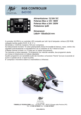
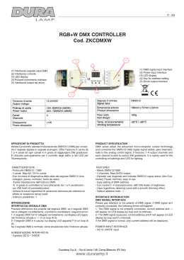
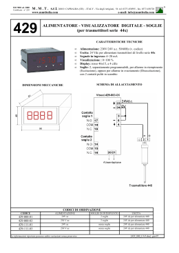
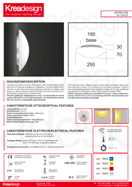
Rev. 0091300211 - 30.04.15
INSTALLATION AND USER’S MANUAL
INTERFACCIA I/O ONE
ONE accessories
INDIRIZZAMENTO DEGLI ACCESSORI (LINEA BUS)
La centrale ONE prevede l’utilizzo di accessori ONE collegati esclusivamente
tramite linea digitale (BUS) a due fili non polarizzati. Ogni accessorio
(lampeggiante, fotocellule RX e TX, selettore a chiave, scheda I/O, …) dovrà
essere collegato con soli due fili (morsetti linea BUS) alla centrale. Sulla linea BUS
transitano sia l’alimentazione che i comandi digitali per il controllo degli accessori.
Ogni accessorio, della stessa famiglia, collegato alla linea BUS dovrà essere
identificato con un ID numerico UNICO (diverso da ogni altro accessorio della
stessa tipologia). L’impostazione ID di ogni accessorio viene effettuata tramite
DIP-SWITCH accessibili in scheda:
IN
OUT
Dip switch ID
BUS
ITALIANO
INTERFACCIA I/O
AVVERTENZE
Il presente manuale di installazione è rivolto esclusivamente a personale
professionalmente competente. Tutto quello che non è espressamente previsto
in queste istruzioni non è permesso.
DESCRIZIONE DEL PRODOTTO E DESTINAZIONE D’USO
La scheda INTERFACCIA I/O ONE è un accessorio della linea ONE collegato
e comandato dalla centrale ONE con solo due fili non polarizzati (linea BUS)
dove transitano sia i comandi digitali sia l’alimentazione necessaria al suo
funzionamento. La scheda INTERFACCIA I/O permette di collegare degli ingressi
(contatto pulito N.O.) ai quali possono essere associati dei funzionamenti
(es APRI-CHIUDI, STOP…) e permette di avere a disposizione delle uscite a
relè o spia anch’esse impostabili (rif. FUNZIONAMENTO DELLA SCHEDA
INTERFACCIA I/O).
La logica di assegnazione degli ID è la seguente:
DIP1 = OFF
ON
1
2
3
DIP1 DIP2
DIP3
1
2
3
DIP1 DIP2
ON
Ingressi
• IN1
• COM
• IN2
ON
Ingresso canale 1 (optoisolato N.O.)
Comune Ingresso
Ingresso canale 2 (optoisolato N.O.)
Uscite
• 24+
• 24-
• C
• NO
Uscita +24V
(20mA max)
Uscita -24V
Comune Uscita Relè
Uscita Relè (N.O. 24V
1A max)
DIP3
DIP2 = OFF
ID = Interfaccia I/O N° 2
DIP3 = OFF
DIP1 = OFF
1
2
3
DIP1 DIP2
DIP3
DIP2 = ON
ID = Interfaccia I/O N° 3
DIP3 = OFF
DIP1 = ON
1
2
3
DIP1 DIP2
DIP3
DIP2 = ON
ID = Interfaccia I/O N° 4
DIP3 = OFF
IMPOSTAZIONE DEL FUNZIONAMENTO (MODE)
DELL’INTERFACCIA I/O
VERIFICHE PRELIMINARI
•Verificare che il prodotto all’interno dell’imballo sia integro ed in buone
condizioni.
Ogni accessorio ha la possibilità di essere impostato nel tipo del suo
FUNZIONAMENTO (es: fotocellula attiva in chiusura, scheda I/O con uscita
SPIA…); questo tipo di configurazione può essere fatta direttamente in scheda
impostando il relativo DIP-SWITCH (MODE). Nel caso della INTERFACCIA I/O si
possono impostare 4 diversi modi di funzionamento:
INSTALLAZIONE
• Collegare i due fili dal morsetto BUS (fig. 1) della scheda INTERFACCIA I/O alla
linea BUS della centrale di controllo ONE in maniera diretta o attraverso altro
accessorio già collegato alla linea BUS. Non è necessario rispettare nessuna
polarità.
• Procedere al collegamento degli ingressi e/o delle uscite che si intendono
utilizzare secondo gli schemi seguenti.
ATTENZIONE: le uscite (24+,24- e C.NO) vengono attivate
contemporaneamente e con lo stesso funzionamento (definito dal dip-switch
MODE). Non è necessario utilizzare entrambi gli ingressi IN1 e IN2 che possono
essere associati a funzioni diverse.
fig. 1
ID = Interfaccia I/O N° 1
DIP3 = OFF
DIP1 = ON
ON
CARATTERISTICHE ELETTRICHE
Bus
• Tensione BUS
22V
• Consumo massimo 20mA 0.5W
DIP2 = OFF
Dip switch MODE
PULSANTE CANALE 1 (N.O.)
INTERFACCIA I/O
ON
1
2
DIP1
DIP2
1
2
DIP1
DIP2
1
2
DIP1
DIP2
1
2
DIP1
DIP2
ON
IN1
COM
LAMPADA SPIA 24V
0.5W
IN2
24V+
24VC
NO
BUS
BUS
ON
CONTATTO N.O. 24V
BUS
1A
DIP1 = OFF FUNZIONAMENTO TIPO 1
IN = [AUTO-PP][PED]
DIP2 = OFF OUT = [AUX]/FUNZIONE APP*
DIP1 = ON
ON
INTERFACCIA I/O di TIPO 2 In=[APRE]\[CHIUDE] Out=AUX:
Ingresso
Utilizzando gli ingressi IN1-COM o IN2-COM si attivano i seguenti comandi:
IN1-COM:
(ingresso optoisolato N.O.) Aziona il comando
APRE (solo apertura)
IN2-COM:
(ingresso optoisolato N.O.) Aziona il comando
CHIUDE (solo chiusura)
Uscita
Sono disponibili due uscite impostate con funzionalità AUX (attivabili
contemporaneamente da ogni radiocomando codificato come AUX- monostabile
3” ON):
24V+
Uscita + per lampada spia 24V
(20mA max)
24V-
Uscita - per lampada spia 24V
NO:
Uscita contatto pulito N.O. (24V
1A max)
C:
Uscita contatto pulito (Comune)
INTERFACCIA I/O di TIPO 3 In=[AUTP-PP]\[STOP] Out=SPIA:
Ingresso
Utilizzando gli ingressi IN1-COM o IN2-COM si attivano i seguenti comandi:
IN1-COM:
(ingresso optoisolato N.O.) Aziona il comando
AUTO-PP (apri-chiudi)
IN2-COM:
(ingresso optoisolato N.O.) Aziona il comando
STOP (blocco automazione)
Uscita
Sono disponibili due uscite impostate con funzionalità SPIA che si attivano
contemporaneamente segnalando lo stato dell’automazione:
24V+
Uscita + per lampada spia 24V
(20mA max)
24V-
Uscita - per lampada spia 24V
NO:
Uscita contatto puro N.O. (24V
1A max)
C:
Uscita contatto puro (Comune)
Uscita lampeggiante = serramento in movimento
Uscita attiva (ON)
= serramento aperto
Uscita disattiva (OFF)
= serramento chiuso
INTERFACCIA I/O di TIPO 4 In=[AUTP-PP]\[PED] Out=SPIA:
Ingresso
Utilizzando gli ingressi IN1-COM o IN2-COM si attivano i seguenti comandi:
BUS
PULSANTE CANALE 2 (N.O.)
INTERFACCIA I/O di TIPO 1 In=[AUTO-PP]\[PED] Out=AUX:
Ingresso
Utilizzando gli ingressi IN1-COM o IN2-COM si attivano i seguenti comandi:
IN1-COM:
(ingresso optoisolato N.O.) Aziona il comando
AUTO-PP (apri-chiudi)
IN2-COM:
(ingresso optoisolato N.O.) Aziona il comando PED
(apertura pedonale)
Uscita
Sono disponibili due uscite impostate con funzionalità AUX (attivabili
contemporaneamente da ogni radiocomando codificato come AUX monostabile 3” ON):
24V+
Uscita + 24V
(20mA max)
24V-
Uscita - 24V
1A max)
NO:
Uscita contatto pulito N.O. (24V
C:
Uscita contatto pulito (Comune)
FUNZIONAMENTO TIPO 2
IN = [APRE][CHIUDE]
DIP2 = OFF OUT = [AUX]
DIP1 = OFF FUNZIONAMENTO TIPO 3
IN = [AUTO-PP][STOP]
DIP2 = ON OUT = [SPIA]
DIP1 = ON
DIP2 = ON
FUNZIONAMENTO TIPO 4
IN = [AUTO-PP][PED]
OUT = [SPIA]
*ATTENZIONE: nel caso di utilizzo dell’app per configurare l’impianto
assicurarsi di impostare il funzionamento (MODE) di TIPO 1.
IN1-COM:
(ingresso optoisolato N.O.) Aziona il comando
AUTO-PP (apri-chiudi)
IN2-COM:
(ingresso optoisolato N.O.) Aziona il comando
PED (apertura pedonale)
Uscita
Sono disponibili due uscite impostate con funzionalità SPIA che si attivano
contemporaneamente segnalando lo stato dell’automazione:
24V+
Uscita + per lampada spia 24V
(20mA max)
24V-
Uscita - per lampada spia 24V
NO:
Uscita contatto puro N.O. (24V
1A max)
C:
Uscita contatto puro (Comune)
Uscita lampeggiante = serramento in movimento
Uscita attiva (ON)
= serramento aperto
Uscita disattiva (OFF)
= serramento chiuso
ENGLISH
DIP1 = OFF
ON
PRESCRIPTIONS
This installation manual is addressed exclusively to professionally skilled
personnel. Any operations that are not expressly envisaged in these instructions
are to be considered prohibited.
PRODUCT DESCRIPTION AND INTENDED USE
The I/O INTERFACE ONE board is an accessory of the ONE line connected and
controlled by the ONE control unit with only 2 non-polarised wires (BUS line),
where both the digital commands and power supply required for the system’s
operation transit. The I/O INTERFACE board allows you to connect the inputs
(NO clean contact), which can be linked to a set of system functions (e.g. OPENCLOSE, STOP, etc.) and allows you to have relay outputs or an indicator light
available, which are also configurable (ref. OPERATION OF I/O INTERFACE
BOARD).
1
2
3
DIP1 DIP2
DIP3
DIP2 = ON
DIP3 = OFF
DIP1 = ON
ON
1
2
3
DIP1 DIP2
DIP3
DIP2 = ON
ID = Interface I/O N° 4
DIP3 = OFF
SETTING THE OPERATION (MODE) OF THE I/O INTERFACE
Each accessory can be set according to its type of OPERATION (e.g.: photocell
activated on closing, I/O board with INDICATOR LIGHT output, etc.); this type
of configuration can be done directly on the board by setting the corresponding
DIP-SWITCH (MODE). You can set 4 different operating modes for the I/O
INTERFACE:
ELECTRICAL SPECIFICATIONS
Bus
• BUS Voltage
22V
• Max. current consumption 20mA 0.5W
Inputs
• IN1
• COM
• IN2
ID = Interface I/O N° 3
Dip switch MODE
Channel 1 input (NO optically insulated)
Common input
Channel 2 input (NO optically insulated)
Output +24V
(20mA max)
Output -24V
Common Relay Output
Relay Output (N.O. 24V
1A max)
INSTALLATION
• Connect the two wires from the BUS terminal (Fig. 1) of the I/O INTERFACE
board to the BUS line of the ONE control unit directly or through another
accessory already connected to the BUS line. No polarity needs to be
observed.
• Proceed to connect the inputs and/or outputs that you intend to use according
to the diagrams below.
NOTE: the outputs (24+,24- and C.NO) are enabled simultaneously and with
the same function (defined by the dip-switch MODE). It is not necessary to
use both inputs IN1 and IN2, which can be associated with different functions.
DIP1 = OFF OPERATION TYPE 1
IN = [AUTO-PP][PED]
OUT = [AUX]/APP FUNDIP2 = OFF CTION*
ON
1
2
DIP1
DIP2
ON
DIP1 = ON
1
2
DIP1
DIP2
1
2
DIP1
DIP2
OPERATION TYPE 2
IN = [OPEN][CLOSE]
DIP2 = OFF OUT = [AUX]
ON
CHANNEL BUTTON 1 (N.O)
DIP1 = OFF OPERATION TYPE 3
IN = [AUTO-PP][STOP]
DIP2 = ON OUT = [INDICATOR LIGHT]
ON
CHANNEL BUTTON 2 (N.O)
DIP1 = ON
1
2
DIP1
DIP2
DIP2 = ON
OPERATION TYPE 4
IN = [AUTO-PP][PED]
OUT = [INDICATOR LIGHT]
*WARNING: if you use the app to configure the system, make sure that you
set the operation (MODE) to TYPE 1.
IN1
COM
INDICATOR LIGHT 24V
0.5W
IN
IN2
OUT
24V+
24VC
N.O. CONTACT 24V
NO
BUS
1A
BUS
BUS
Dip switch ID
BUS
I/O INTERFACE
The ID assignment logic is as follows:
DIP1 = OFF
1
2
DIP1 DIP2
3
DIP3
DIP2 = OFF
ID = Interface I/O N° 1
DIP3 = OFF
DIP1 = ON
ON
1
2
DIP1 DIP2
3
DIP3
DIP2 = OFF
DIP3 = OFF
I/O INTERFACE TYPE 4 In=[AUTP-PP]\[PED] Out=INDICATOR LIGHT:
Input
When inputs IN1-COM o IN2-COM are used, the following commands will be
activated:
IN1-COM:
(NO optically insulated input) Activates the command
Auto-PP (open-close)
IN2-COM:
(NO optically insulated input) Activates the command
PED (pedestrian opening)
Output
There are two outputs set to INDICATOR LIGHT function that are activated
simultaneously, signalling the status of automation:
24V+
Output + for indicator light 24V
(20mA max)
24V-
Output - for indicator light 24V
NO:
Clean N.O. contact output (24V
1A max)
C:
Clean contact output (common)
Flashing light output = gate moving
Output activated (ON)
= gate open
Output deactivated (OFF) = gate closed
PRODUKTBESCHREIBUNG UND BESTIMMUNGSZWECK
Die INTERFACE I/O SCHNITTSTELLE ONE ist ein Zubehör der Produktlinie
ONE, das an die Steuerung ONE angeschlossen und von ihr gesteuert wird
und nur zwei ungepolte Leiter (BUS-Leitung) für die digitalen Schaltungen wie
auch die für seinen Betrieb notwendige Speisung besitzt. Die INTERFACE I/O
SCHNITTSTELLE ONE erlaubt den Anschluss der Eingänge (sauberer NOKontakt), denen Funktionen zugeordnet werden können (z.B. AUF-ZU, STOP,
...) und stellen ebenfalls einstellbare Relais- oder Kontrolllampenausgänge zur
Verfügung (siehe BETRIEB DER KARTE I/O-SCHNITTSTELLE).
ELEKTRISCHE EIGENSCHAFTEN
Bus
• Spannung BUS
22V
• Max. Verbrauch 20mA 0.5W
Eingänge
• IN1
• COM
• IN2
Eingang Kanal 1 (optoisoliert N.O.)
Common Eingang
Eingang Kanal 2 (optoisoliert N.O.)
Ausgänge
• 24+
• 24-
• C
• NO
Ausgang +24V
(20mA max)
Ausgang -24V
Common Relaisausgang
Relaisausgang (N.O. 24V
1A max)
VORBEREITENDE KONTROLLEN
• Prüfen, dass das in der Verpackung enthaltene Produkt einwandfrei und in
gutem Zustand ist.
INSTALLATION
• Die zwei Leiter von der BUS-Klemme (Abb. 1) der Karte I/O-SCHNITTSTELLE
direkt oder über ein anderes, bereits an die BUS-Leitung angeschlossenes
Zubehör an die BUS-Leitung der Steuerung ONE anschließen. Es ist keine
Polung zu beachten.
• Die Eingänge und/oder Ausgänge anschließen, die man gemäß folgender
Schemen verwenden möchte.
ACHTUNG: Die Ausgänge (24+,24- und C.NO) werden nicht gleichzeitig und
mit der gleichen Funktion aktiviert (vom Dip-Switch MODE bestimmt). Es ist nicht
notwendig, beide Eingänge IN1 und IN2 zu benutzen; sie können verschiedenen
Funktionen zugeordnet werden.
abb. 1
ACCESSORY ADDRESS ASSIGNMENT (BUS LINE)
The ONE control unit requires the use of ONE accessories connected exclusively
through digital (BUS) line with 2 non-polarised wires. All accessories (flashing
light, photocells RX and TX, key switch, I/O board, etc.) must be connected with
only two wires (BUS line terminals) to the control unit. Both the power supply
and digital commands to control the accessories transit on the BUS line. Each
accessory of the same family connected to the BUS line must be identified by
a UNIQUE numeric ID (different from all other accessories of the same type).
Setting the ID of each accessory is done through the DIP-SWITCHES accessible
in the board:
ON
1A max)
HINWEIS
Dieses Installationshandbuch wendet sich ausschließlich an professionell
kompetentes Personal. Alle nicht ausdrücklich in dieser Anleitung erwähnten
Vorgänge sind nicht erlaubt.
I/O INTERFACE
PRELIMINARY CHECKS
• Check that the product in the pack is intact and in good condition.
fig. 1
Output - for indicator light 24V
Uscita contatto puro N.O. (24V
Clean contact output (common)
= gate moving
= gate open
= gate closed
DEUTSCH
BUS
Outputs
• 24+
• 24-
• C
• NO
24V-
NO:
C:
Flashing light output Output activated (ON)
Output deactivated (OFF)
ID = Interface I/O N° 2
I/O INTERFACE TYPE 1 In=[AUTO-PP]\[PED] Out=AUX:
Input
Using the inputs IN1-COM or IN2-COM-COM will activate the following
commands:
IN1-COM:
(NO optically insulated input) Activates the command
Auto-PP (open-close)
IN2-COM:
(NO optically insulated input) Activates the PED
command (pedestrian opening)
Output
There are two outputs set to AUX function (which can be enabled simultaneously
by each remote control encoded as AUX - monostable 3” ON):
24V+
Output + 24V
(20mA max)
24V-
Output - 24V
NO:
Clean N.O. contact output (24V
1A max)
C:
Clean contact output (common)
I/O INTERFACE TYPE 2 In=[OPEN]\[CLOSE] Out=AUX:
Input
Using inputs IN1-COM or IN2-COM-COM will activate the following commands:
IN1-COM:
(NO optically insulated input) Activates the command
OPEN (opening only)
IN2-COM:
(NO optically insulated input) Activates the command
CLOSE (closing only)
Output
There are two outputs set to AUX function (which can be enabled simultaneously
by each remote control encoded as AUX - monostable 3” ON):
24V+
Output + or indicator light 24V
(20mA max)
24V-
Output - or indicator light 24V
NO:
Clean N.O. contact output (24V
1A max)
C:
Clean contact output (common)
I/O INTERFACE TYPE 3 In=[AUTP-PP]\[STOP]Out=INDICATOR LIGHT:
Input
Using the inputs IN1-COM or IN2-COM-COM will activate the following commands:
IN1-COM:
(NO optically insulated input) Activates the command
Auto-PP (open-close)
IN2-COM:
(NO optically insulated input) Activates the command
STOP (stop automation)
Output
There are two outputs set to INDICATOR LIGHT function that are activated
simultaneously, signalling the status of automation:
24V+
Output + for indicator light 24V
(20mA max)
TASTER KANAL 1 (N.O.)
TASTER KANAL 2 (N.O.)
IN1
COM
KONTROLLLAMPE 24V
0.5W
IN2
24V+
24VC
NO
BUS
BUS
N.O.-KONTAKT 24V
1A
BUS
ADRESSIERUNG DER ZUBEHÖRE (BUS-LEITUNG)
Die Steuerung ONE verlangt die Verwendung von ONE-Zubehören, die
ausschließlich mittels Digitalleitung (BUS) mit zwei ungepolten Leitern
angeschlossen werden. Jedes Zubehör (Blinkleuchte, Fotozellen RX u. TX,
Schlüsselwählschalter, INTERFACE-I/O, ...) ist mit nur zwei Leitern (Klemmen
BUS-Leitung) an die Steuerung anzuschließen. Auf der BUS-Leitung transitieren
sowohl die Speisung wie auch die digitalen Schaltungen für die Kontrolle der
Zubehöre. Jedes an die BUS-Leitung angeschlossene Zubehör der gleichen
Familie ist mit einer EINZIGEN ID-Nummer zu identifizieren (anders als jedes
andere Zubehör der gleichen Typologie). Die ID-Nummer jedes Zubehörs wird mit
den DIP-SWITCHES auf der Karte eingestellt:
FRATELLI COMUNELLO S.P.A. AUTOMATION GATE DIVISION
Via Cassola, 64 - C.P. 79 36027 Rosà, Vicenza, Italy | Tel. +39 0424 585111 Fax +39 0424 533417 | [email protected] www.comunello.com
Dip switch ID
BUS
INTERFACE I/O
Die ID-Zuordnungslogik ist die Folgende:
DIP1 = OFF
ON
1
2
3
DIP1 DIP2
DIP3
DIP2 = OFF
ID = Interface I/O N° 1
DIP3 = OFF
DIP1 = ON
ON
1
2
3
DIP1 DIP2
DIP3
DIP2 = OFF
ID = Interface I/O N° 2
DIP3 = OFF
DIP1 = OFF
ON
1
2
3
DIP1 DIP2
DIP3
DIP2 = ON
ID = Interface I/O N° 3
DIP3 = OFF
DIP1 = ON
ON
1
2
3
DIP1 DIP2
DIP3
DIP2 = ON
ID = Interface I/O N° 4
DIP3 = OFF
EINSTELLUNG DER BETRIEBSART (MODE)
DER I/O-SCHNITTSTELLE
Auf jedem Zubehör kann seine BETRIEBSART eingestellt werden (z.B.: Fotozelle
beim Schließen aktiv, I/O-Karte mit Ausgang KONTROLLLAMPE, ...); diese Art
der Konfiguration kann direkt auf der Karte durch Einstellung des entsprechenden
DIP-SWITCHES (MODE) erfolgen. Im Falle der I/O-SCHNITTSTELLE können 4
verschiedene Betriebsarten eingestellt werden:
Dip switch MODE
INTERFACE I/O
1
2
DIP1
DIP2
DIP1 = OFF BETRIEBSART 1
IN = [AUTO-PP][PED]
DIP2 = OFF OUT = [AUX]/FUNKTION APP*
ON
DIP1 = ON
1
2
DIP1
DIP2
BETRIEBSART 2
IN = [AUF][ZU]
DIP2 = OFF OUT = [AUX]
ON
1
2
DIP1
DIP2
DIP1 = OFF BETRIEBSART 3
IN = [AUTO-PP][STOP]
DIP2 = ON OUT = [KONTROLLLAMPE]
ON
DIP1 = ON
1
2
DIP1
DIP2
DIP2 = ON
BETRIEBSART 4
IN = [AUTO-PP][PED]
OUT = [KONTROLLLAMPE]
*ACHTUNG: Falls die App zur Konfiguration der Anlage benutzt wird, ist
unbedingt die Betriebsart (MODE) vom TYP 1 einzustellen.
IN
OUT
I/O-SCHNITTSTELLE TYP 1 In=[AUTO-PP]\[PED] Out=AUX:
Eingang
Bei Benutzung der Eingänge IN1-COM oder IN2-COM werden folgende
Betätigungen aktiviert:
IN1-COM:
(optoisolierter N.O.-Eingang) Betätigt die Schaltung
AUTO-PP (Auf-Zu)
IN2-COM:
(optoisolierter N.O.-Eingang) Betätigt die
PED-Schaltung (Fußgängeröffnung)
Ausgang
Es sind zwei Ausgänge verfügbar, die mit der AUX-Funktion eingestellt
fig. 1
BOUTON VOIE 1 (N.O.)
I/O-SCHNITTSTELLE TYP 2 In=[AUF]\[ZU] Out=AUX:
Eingang
Bei Benutzung der Eingänge IN1-COM oder IN2-COM werden folgende
Betätigungen aktiviert:
IN1-COM:
(optoisolierter NO-Eingang) Betätigt die Schaltung
AUF (nur Öffnung)
IN2-COM:
(optoisolierter NO-Eingang) Betätigt die Schaltung
ZU (nur Schließung)
Ausgang
Es sind zwei Ausgänge verfügbar, die mit der AUX-Funktion eingestellt
sind (gleichzeitig aktivierbar von jeder als AUX – monostabil 3“ ON codierten
Funksteuerung):
24V+
Ausgang + für Kontrolllampe 24V
(20mA max)
24V-
Ausgang - für Kontrolllampe 24V
NO:
Ausgang sauberer N.O.-Kontakt(24V
1A max)
C:
Ausgang sauberer Kontakt (Common)
I/O-SCHNITTSTELLE TYP 3 In=[AUTO-PP]\[STOP] Out=KONTROLLLAMPE:
Eingang
Bei Benutzung der Eingänge IN1-COM oder IN2-COM werden folgende
Betätigungen aktiviert:
IN1-COM:
(optoisolierter NO-Eingang) Betätigt die Schaltung
AUTO-PP (Auf-Zu)
IN2-COM:
(optoisolierter NO-Eingang) Betätigt die Schaltung
STOP (Antriebssperre)
Ausgang
Es sind zwei auf die Funktion KONTROLLLAMPE eingestellte Ausgänge verfügbar,
die gleichzeitig aktiv werden und den Zustand des Antriebes anzeigen:
24V+
Ausgang + für Kontrolllampe 24V
(20mA max)
24V-
Ausgang - für Kontrolllampe 24V
NO:
Ausgang sauberer N.O.-Kontakt (24V
1A max)
C:
Ausgang sauberer Kontakt (Common)
Ausgang Blinkleuchte = Tor in Bewegung
Ausgang aktiv (ON) = Tor geöffnet
Ausgang nicht aktiv (OFF) = Tor geschlossen
BOUTON VOIE 2 (N.O.)
IN1
COM
VOYANT 24 V
0,5 W
IN2
24V+
24VC
CONTACT N.O. 24 V
NO
BUS
1A
BUS
BUS
ADRESSAGE DES ACCESSOIRES (LIGNE BUS)
L’unité centrale ONE permet exclusivement d’utiliser les accessoires ONE via
ligne numérique (BUS) à deux fils non polarisés. Tous les accessoires (clignotant,
photocellules RX et TX, sélecteur à clé, carte I/O, etc.) devront être branchés
au moyen de deux fils seulement (bornes ligne BUS) à l’unité centrale. La ligne
BUS achemine l’alimentation et les commandes numériques des accessoires.
Chaque accessoire de la même famille branché à la ligne BUS devra porter un
identifiant (ID) numérique UNIQUE (différent des autres accessoires du même
type). L’ID de chaque accessoire est configuré via les DIP-SWITCH accessibles
sur la carte:
Dip switch ID
I/O-SCHNITTSTELLE TYP 4 In=[AUTO-PP]\[PED] Out=KONTROLLLAMPE:
Eingang
Bei Benutzung der Eingänge IN1-COM oder IN2-COM werden folgende
Betätigungen aktiviert:
IN1-COM:
IN2-COM:
Ausgang
(optoisolierter NO-Eingang) Betätigt die Schaltung
AUTO-PP (Auf-Zu)
(optoisolierter NO-Eingang) Betätigt die Schaltung
PED (Fußgängeröffnung)
Es sind zwei auf die Funktion KONTROLLLAMPE eingestellte Ausgänge verfügbar,
die gleichzeitig aktiv werden und den Zustand des Antriebes anzeigen:
24V+
Ausgang + für Kontrolllampe 24V
(20mA max)
24V-
Ausgang - für Kontrolllampe 24V
NO:
Ausgang sauberer N.O.-Kontakt (24V
1A max)
C:
Ausgang sauberer Kontakt (Common)
Ausgang Blinkleuchte = Tor in Bewegung
Ausgang aktiv (ON) = Tor geöffnet
Ausgang nicht aktiv (OFF) = Tor geschlossen
BUS
ON
sind (gleichzeitig aktivierbar von jeder als AUX – monostabil 3“ ON codierten
Funksteuerung):
24V+
Ausgang + 24V
(20mA max)
24V-
Ausgang - 24V
NO:
Ausgang sauberer N.O.-Kontakt(24V
1A max)
C:
Ausgang sauberer Kontakt (Common)
BUS
INTERFACE I/O
La logique d’assignation des ID est la suivante:
DIP1 = OFF
ON
1
FRANÇAIS
2
3
DIP1 DIP2
AVERTISSEMENTS
Ce manuel d’installation est exclusivement destiné au personnel compétent.
Toutes les opérations non expressément prévues dans ces instructions sont
interdites.
ON
DESCRIPTION DU PRODUIT ET UTILISATION PRÉVUE
La carte INTERFACE I/O ONE est un accessoire de la ligne ONE relié à l’unité
centrale ONE et commandé par cette dernière via deux fils non polarisés (ligne
BUS) qui acheminent les commandes numériques et l’alimentation nécessaire
à son fonctionnement. La carte INTERFACE I/O ONE permet de raccorder des
entrées (contact sec NO) éventuellement associées à des actionnements (ex.
OUVERTURE-FERMETURE, STOP…) et de disposer de sorties relais ou voyants
également configurables (réf. FONCTIONNEMENT DE LA CARTE INTERFACE
I/O).
ON
CARACTÉRISTIQUES ÉLECTRIQUES
Bus
• Tension BUS
22V
• Consommation maximale 20mA 0.5W
Entrées
• IN1 • COM • IN2 Entrée voie 1 (opto-isolée N.O.)
Entrée commune
Entrée voie 2 (opto-isolée N.O.)
Sorties
• 24+
• 24-
• C
• NO
Sortie +24V
(20mA max)
Sortie -24V
Commune sortie relais
Sortie relais (N.O- 24 V 1 A max.)
DIP3
ID = Interface I/O N° 1
DIP3 = OFF
DIP1 = ON
1
2
3
DIP1 DIP2
DIP3
DIP2 = OFF
ID = Interface I/O N° 2
DIP3 = OFF
DIP1 = OFF
1
2
3
DIP1 DIP2
DIP3
DIP2 = ON
ID = Interface I/O N° 3
DIP3 = OFF
DIP1 = ON
ON
1
2
3
DIP1 DIP2
DIP3
DIP2 = ON
ID = Interface I/O N° 4
DIP3 = OFF
CONFIGURATION (MODE) DE L’INTERFACE I/O
Le type de FONCTIONNEMENT de chaque accessoire peut être configuré (ex.
photocellule activée, carte I/O à sortie VOYANT, etc.) ; ce type de configuration
peut être directement effectué sur la carte en paramétrant le DIP-SWITCH
correspondant (MODE). Dans le cas de l’INTERFACE I/O, 4 modes de
fonctionnement sont prévus:
Dip switch MODE
CONTRÔLES PRÉLIMINAIRES
• Vérifier que le produit contenu dans l’emballage est en parfait état.
INSTALLATION
• Raccorder les deux fils de la borne BUS (fig. 1) de la carte INTERFACE I/O
à la ligne BUS de l’unité centrale de contrôle ONE, directement ou via autre
accessoire déjà raccordé à la ligne BUS. Les polarités sont sans importance.
• Raccorder les entrées et/ou sorties prévues pour être utilisées selon les
schémas suivants.
ATTENTION : les sorties (24+,24- et C.NO) sont activées simultanément et
selon un fonctionnement identique (défini par le dip-switch MODE). Il n’est pas
nécessaire d’utiliser les deux entrées IN1 et IN2, qui peuvent être associées à
d’autres fonctions.
DIP2 = OFF
BUS
INTERFACCIA I/O
ON
1
2
DIP1
DIP2
ON
DIP1 = OFF FONCTIONNEMENT TYPE 1
IN = [AUTO-PP][PED]
DIP2 = OFF OUT = [AUX]/FONCTION APP*
FONCTIONNEMENT TYPE 2
IN = [OUVERTURE][FERMETURE]
DIP2 = OFF OUT = [AUX]
DIP1 = ON
1
2
DIP1
DIP2
ON
1
2
DIP1
DIP2
DIP1 = OFF FONCTIONNEMENT TYPE 3
IN = [AUTO-PP][STOP]
DIP2 = ON OUT = [VOYANT]
FRATELLI COMUNELLO S.P.A. AUTOMATION GATE DIVISION
Via Cassola, 64 - C.P. 79 36027 Rosà, Vicenza, Italy | Tel. +39 0424 585111 Fax +39 0424 533417 | [email protected] www.comunello.com
ON
DIP1 = ON
1
2
DIP1
DIP2
DIP2 = ON
FONCTIONNEMENT TYPE 4
IN = [AUTO-PP][PED]
OUT = [VOYANT]
*ATTENTION: en cas de configuration du système au moyen de l’application,
sélectionner le fonctionnement (MODE) de TYPE 1.
• COM
• IN2
Común Entrada
Entrada canal 2 (optoaislada N.A.)
Salidas
• 24+
• 24-
• C
• NO
Salidas +24V
(20mA máx)
Salidas -24V
Común Salida Relé
Salida Relé (N.O. 24V
1A máx)
Dip switch MODE
CONTROLES PRELIMINARES
• Compruebe que el producto embalado esté íntegro y en buenas condiciones.
IN
INSTALACIÓN
• Conecte los dos hilos desde el borne BUS (fig. 1) de la tarjeta INTERFAZ E/S
a la línea BUS del cuadro de control ONE en forma directa o a través de otro
accesorio ya conectado a la línea BUS. No es necesario respetar la polaridad.
• Conecte las entradas y/o las salidas que se deben utilizar de acuerdo con los
siguientes diagramas.
ATENCIÓN: las salidas (24+, 24- y C.NO) se activan simultáneamente y con
el mismo funcionamiento (definido por el dip-switch MODE). No es necesario
utilizar ambas entradas IN1 y IN2 que se pueden asociar a diferentes funciones.
OUT
fig. 1
PULSADOR CANAL 1 (N.A.)
INTERFACE I/O di Type 1 In=[AUTO-PP]\[PED] Out=AUX:
Entrée
Les entrées IN1-COM ou IN2-COM permettent d’activer les commandes
suivantes:
IN1-COM:
(entrée opto-isolée NO) Actionne la commande
AUTO-PP (ouverture-fermeture)
IN2-COM:
(entrée opto-isolée NO) Actionne la commande PED
(ouverture piétons)
Sortie
Deux sorties configurées comme AUX sont disponibles (activables simultanément
sur chaque radiocommande codifiée comme AUX - monostable 3” ON):
24V+
Sortie + 24V
(20mA max)
24V-
Sortie - 24V
NO:
Sortie contact sec N.O. (24V
1A max)
C:
Sortie contact sec (commune)
INTERFACE I/O di Type 2 In=[OUVERTURE]\[FERMETURE] Out=AUX:
Entrée
Les entrées IN1-COM ou IN2-COM permettent d’activer les commandes suivantes:
IN1-COM:
(entrée opto-isolée N.O.) Actionne la commande
OUVERTURE (ouverture seule)
IN2-COM:
(entrée opto-isolée N.O.) Actionne la commande
FERMETURE (fermeture seule)
Sortie
Deux sorties configurées comme AUX sont disponibles (activables simultanément
sur chaque radiocommande codifiée comme AUX - monostable 3” ON):
24V+
Sortie + pour voyant 24V
(20mA max)
24V-
Sortie - pour voyant 24V
NO:
Sortie contact sec N.O. (24V
1A max)
C:
Sortie contact sec (commune)
INTERFACE I/O de TYPE 3 In=[AUTP-PP]\[STOP] Out=VOYANT:
Entrée
Les entrées IN1-COM ou IN2-COM permettent d’activer les commandes suivantes:
IN1-COM:
(entrée opto-isolée N.O.) Actionne la commande
AUTO-PP (ouverture-fermeture)
IN2-COM:
entrée opto-isolée N.O.) Actionne la commande
STOP (arrêt automatisme)
Sortie
Deux sorties configurées comme VOYANT sont disponibles et s’activent
simultanément pour signaler l’état de l’automatisme:
24V+
Sortie + pour voyant 24V
(20mA max)
24V-
Sortie - pour voyant 24V
NO:
Sortie contact sec N.O. (24V
1A max)
C:
Sortie contact sec (commune)
Sortie clignotant = portail en mouvement
Sortie activée (ON) = portail ouvert
Sortie désactivée (OFF) = portail fermé
INTERFACE I/O de TYPE 4 In=[AUTP-PP]\[PED] Out=VOYANT:
Entrée
Les entrées IN1-COM ou IN2-COM permettent d’activer les commandes suivantes:
IN1-COM:
(entrée opto-isolée N.O.) Actionne la commande
AUTO-PP (ouverture-fermeture)
IN2-COM:
(entrée opto-isolée N.O.) Actionne la commande
PED (ouverture piétons)
Sortie
Deux sorties configurées comme VOYANT sont disponibles et s’activent
simultanément pour signaler l’état de l’automatisme:
24V+
Sortie + pour voyant 24V
(20mA max)
24V-
Sortie - pour voyant 24V
NO:
Sortie contact sec N.O. (24V
1A max)
C:
Sortie contact sec (commune)
Sortie clignotant = portail en mouvement
Sortie activée (ON)
= portail ouvert
Sortie désactivée (OFF) = portail fermé
ESPAÑOL
COM
CARACTERÍSTICAS ELÉCTRICAS
Bus
• Tensión BUS
22V
• Consumo máximo 20mA 0.5W
Entrada canal 1 (optoaislada N.A.)
LUZ TESTIGO 24V
0.5W
IN2
DIP1 = OFF FUNCIONAMIENTO TIPO 1
ENTRADA = [AUTO-PP][PED]
SALIDA = [AUX]/FUNCIÓN
DIP2 = OFF APP*
ON
1
2
DIP1
DIP2
FUNCIONAMIENTO TIPO 2
ENTRADA = [ABRIR]
[CERRAR]
DIP2 = OFF SALIDA = [AUX]
ON
DIP1 = ON
1
2
DIP1
DIP2
DIP1 = OFF FUNCIONAMIENTO TIPO 3
ENTRADA = [AUTO-PP]
[PED]
DIP2 = ON SALIDA = [LUZ TESTIGO]
ON
1
2
DIP1
DIP2
DIP1 = ON
1
2
DIP1
DIP2
DIP2 = ON
FUNCIONAMIENTO TIPO 4
ENTRADA = [AUTO-PP]
[PED]
SALIDA = [LUZ TESTIGO]
*ATENCIÓN: si se utiliza la app para configurar el sistema, asegúrese de
configurar el funcionamiento (MODE) TIPO 1.
24V+
24VC
CONTACTO N.A. 24V
NO
BUS
1A
BUS
BUS
Dip switch ID
BUS
INTERFAZ E/S
La lógica de asignación de los ID es la siguiente:
DIP1 = OFF
ON
1
2
DIP1 DIP2
3
DIP3
DIP2 = OFF
ID = Interfaz E/S N° 1
DIP3 = OFF
DIP1 = ON
ON
1
2
DIP1 DIP2
3
DIP3
DIP2 = OFF
ID = Interfaz E/S N° 2
DIP3 = OFF
DIP1 = OFF
ON
1
2
3
DIP3
DIP2 = ON
ID = Interfaz E/S N° 3
DIP3 = OFF
DIP1 = ON
1
2
DIP1 DIP2
3
DIP3
DIP2 = ON
IN
OUT
DIRECCIONAMIENTO DE LOS ACCESORIOS (LÍNEA BUS)
El cuadro de control ONE utiliza los accesorios ONE conectados exclusivamente
mediante la línea digital (BUS) de dos hilos no polarizados. Cada accesorio (luz
intermitente, fotocélulas RX-receptor y TX-transmisor, selector de llave, tarjeta
E/S, etc.) deberá ser conectado con solo dos hilos (bornes línea BUS) al cuadro
de control. Por la línea BUS pasan la alimentación y los mandos digitales para
controlar los accesorios. Cada accesorio de la misma familia conectado a la línea
BUS deberá ser identificado con un ID numérico ÚNICO (diferente de cualquier
otro accesorio del mismo tipo). El ID de cada accesorio se configura mediante
DIP-SWITCHES accesibles en la tarjeta:
ON
DESCRIPCIÓN DEL PRODUCTO Y USO PREVISTO
La tarjeta INTERFAZ E/S ONE es un accesorio de la línea ONE conectado y
accionado desde el cuadro de control ONE con tan solo dos hilos no polarizados
(línea BUS) por donde pasan los mandos digitales y la alimentación que sirve
para su funcionamiento. Con la tarjeta INTERFAZ E/S se pueden conectar
las entradas (contacto seco N.A.) a las que se pueden asociar diferentes
accionamientos (por ej. ABRIR-CERRAR, PARADA, etc.) y permite tener a
disposición algunas salidas de relé o luces testigos también configurables (ref.
FUNCIONAMIENTO DE LA TARJETA INTERFAZ E/S).
INTERFAZ E/S
ON
IN1
DIP1 DIP2
ADVERTENCIAS
El presente manual de instalación está dirigido exclusivamente a personal
profesionalmente capacitado. Todo aquello que no está previsto expresamente
en estas instrucciones no está permitido.
Entradas
• IN1
PULSADOR CANAL 2 (N.A.)
BUS
ID = Interfaz E/S N° 4
DIP3 = OFF
CONFIGURACIÓN DEL FUNCIONAMIENTO (MODE)
DE LA INTERFAZ E/S
Cada accesorio tiene la posibilidad de ser configurado en su tipo de
FUNCIONAMIENTO (por ej.: fotocélula activa durante el cierre, tarjeta E/S
con salida LUZ TESTIGO, etc.); este tipo de configuración puede hacerse
directamente en la tarjeta configurando el respectivo DIP-SWITCH (MODE). En
el caso de la INTERFAZ E/S se pueden configurar 4 modos de funcionamiento
diferentes:
INTERFAZ E/S TIPO 1 Entrada=[AUTO-PP]\[PED] Salida=AUX:
Entrada
Utilizando las entradas IN1-COM o IN2-COM se activan los siguientes mandos:
IN1-COM:
(entrada optoaislada N.A.) Acciona el mando
AUTO-PP (abrir-cerrar)
IN2-COM:
(entrada optoaislada N.A.) Acciona el mando PED
(apertura peatonal)
Salida
Hay disponibles dos salidas configuradas con la funcionalidad AUX (que
se activan simultáneamente en cada radiomando codificado como AUX monoestable 3” ON):
24V+
Salida + 24V
(20mA máx)
24V-
Salida - 24V
NO:
Salida contacto seco N.A. (24V
1A máx)
C:
Salida contacto seco (Común)
INTERFAZ E/S TIPO 2 Entrada=[ABRIR]\[CERRAR] Salida=AUX:
Entrada
Utilizando las entradas IN1-COM o IN2-COM se activan los siguientes mandos:
IN1-COM:
(entrada optoaislada N.A.) Acciona el mando
ABRIR (solo apertura)
IN2-COM:
(entrada optoaislada N.A.) Acciona el mando
CERRAR (solo cierre)
Salida
Hay disponibles dos salidas configuradas con la funcionalidad AUX (que
se activan simultáneamente en cada radiomando codificado como AUX monoestable 3” ON):
24V+
Salida + para luz testigo 24V
(20mA máx)
24V-
Salida - para luz testigo 24V
NO:
Salida contacto seco N.A. (24V
1A máx)
C:
Salida contacto seco (Común)
INTERFAZ E/S TIPO 3 Entrada=[AUTO-PP]\[STOP] Salida=LUZ TESTIGO:
Entrada
Utilizando las entradas IN1-COM o IN2-COM se activan los siguientes mandos:
IN1-COM:
(entrada optoaislada N.A.) Acciona el mando
AUTO-PP (abrir-cerrar)
IN2-COM:
(entrada optoaislada N.A.) Acciona el mando
PARADA (bloqueo automatización)
Salida
Hay disponibles dos salidas configuradas con la funcionalidad LUZ TESTIGO que se
activan simultáneamente señalando el estado de la automatización:
24V+
Salida + para luz testigo 24V
(20mA máx)
24V-
Salida - para luz testigo 24V
NO:
Salida contacto húmedo N.A. (24V
1A máx)
C:
Salida contacto húmedo (Común)
Salida luz intermitente = cerramiento moviéndose
Salida activa (ON) = cerramiento abierto
Salida desactivada (OFF) = cerramiento cerrado
INTERFAZ E/S TIPO 4 Entrada=[AUTO-PP]\[PED] Salida=LUZ TESTIGO:
Entrada
Utilizando las entradas IN1-COM o IN2-COM se activan los siguientes mandos:
IN1-COM:
(entrada optoaislada N.A.) Acciona el mando
AUTO-PP (abrir-cerrar)
IN2-COM:
(entrada optoaislada N.A.) Acciona el mando
PED (apertura peatonal)
Salida
Hay disponibles dos salidas configuradas con la funcionalidad LUZ TESTIGO que se
activan simultáneamente señalando el estado de la automatización:
24V+
Salida + para luz testigo 24V
(20mA máx)
24V-
Salida - para luz testigo 24V
NO:
Salida contacto húmedo N.A. (24V
1A máx)
C:
Salida contacto húmedo (Común)
Salida luz intermitente = cerramiento moviéndose
Salida activa (ON)
= cerramiento abierto
Salida desactivada (OFF) = cerramiento cerrado
FRATELLI COMUNELLO S.P.A. AUTOMATION GATE DIVISION
Via Cassola, 64 - C.P. 79 36027 Rosà, Vicenza, Italy | Tel. +39 0424 585111 Fax +39 0424 533417 | [email protected] www.comunello.com
Scaricare