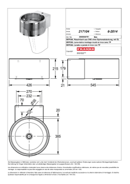
velta Fußbodenheizung
Montage-/Betriebsanleitung
Kompaktverteiler 6/01
Mounting/operating instructions • velta compact distributor
Montage-/bedieningshandleiding • velta kompaktverdeler
Instructions d’installation et d’utilisation • velta distributeur compact
Istruzioni di montaggio e d’uso • velta collettore compatto
R
V
■
■
■
■
■
Für künftige Verwendung aufbewahren!
Keep for future reference!
Voor toekomstig gebruik bewaren!
A conserver pour un usage futur!
Le istruzioni d’uso devono essere
conservate per futuri impieghi!
www.velta.com
Inhalt
Contents
Inhoud
Sommaire
Indice
■
■
■
■
■
Vor der Montage des velta Kompaktverteilers muß der Monteur diese Montage-/Betriebsanleitung
(vor allem das Kapitel „Sicherheit“) lesen, verstehen und beachten.
STOP
Before mounting the velta compact distributor, the fitter muster read, understand and observe
these mounting-/operating instructions (especially the chapter „Safety“).
Voor het monteren van de velta compactverdelers dient de monteur deze montage/gebruikershandleiding (vooral
het hoofdstuk veiligheid) te lezen begrijpen en op te volgen.
Pur le montage du distributeur compact velta, l’installateur doit lire, comprendre et respecter les instructions de
montage/l‚emploi (particulièrement le chapitre „Sécurité“).
Prima del montaggio del distributore compatto velta è indispensabile che l’addetto al montaggio legga, capisca e
rispetti le presenti Istruzioni di montaggio/Istruzioni per l’uso (ed in modo particolare il capitolo „Sicurezza“)
D
1 Sicherheit
1.1 Bestimmungsgemäße Verwendung .................................
1.2 Sicherheitshinweise und Tips .........................................
1.3 Zugelassene Monteure ..................................................
2 Komponenten Kompaktverteiler/Anschlussmöglichkeiten
am Kompaktverteiler ............................................................
3 Montage
3.1 Kompaktverteiler Unterputz montieren ............................
3.2 Kompaktverteiler Aufputz montieren/
Kompensatoren montieren ............................................
4
4
4
6
7
8
3.3 Rohr montieren/Heizkreis-Rohrlänge ....................... 9 – 10
4 Inbetriebnahme
4.1 Anlage füllen/spülen/entlüften .................................... 11
4.2 Druckprobe/Funktionstest ........................................... 12
5 Einstellungen der Vorlaufventile/
Einstellung des Vorlauf-Kugelhahnes ................................... 13
6 Betrieb/Pflege ................................................................... 14
7 Technische Daten Kompaktverteiler .................................... 15
8 Formblatt zur Ermittlung der tatsächlichen Heizkreisrohrlängen und Nachrechnung der Ventileinstellung ............. 16
GB
1 Safety
1.1 Designated application .................................................. 4
1.2 Safety instructions and tips ........................................... 4
1.3 Permitted mounting personnel ....................................... 4
2 Components of the compact distributor/Options for
connecting the compact distributor ...................................... 6
3 Mounting
3.1 Compact distributor mounted under the plaster ............... 7
3.2 Compact distributor mounted on the plaster/
Mounting the compensator ............................................ 8
3.3 Mounting the pipe/Heating circuit pipe length .......... 9 – 10
4 Operation
4.1 Putting the system into operation and flushing it/
venting .......................................................................
4.2 Pressure test/Functional test ......................................
5 Adjustment of the inlet valves/
Adjustment of the inlet ball valve ........................................
6 Operation/Care ..................................................................
7 Technical data compact distributor .....................................
8 Form for determining the actual pipe length of the
heating circuit and checking of the valve setting .................
11
12
13
14
15
16
NL
1 Veiligheid
1.1 Doelmatig gebruik ......................................................... 4
1.2 Veiligheidsaanwijzingen en tips ...................................... 4
1.3 Vakbekwame monteurs ................................................. 5
2 De kompaktverdeler onderdelen/Aansluitmogelijkheden
aan de kompaktverdeler ....................................................... 6
3 Montage
3.1 Monteren kompaktverdeler als inbouw ............................ 7
3.2 Monteren kompaktverdeler als obouw/
Compensatoren monteren ............................................. 8
3.3 Buis monteren/Groep- buislengte ............................... 9-10
4 Inbedrijfstellen
4.1 Installatie vullen en spoelen/ontluchten .......................
4.2 Afpersen/Functietest ..................................................
5 Instellen van de aanvoerventielen/
Instellen van de aanvoer-kogelkraan ....................................
6 Gebruik/Onderhoud ............................................................
7 Technische gegevens kompaktverdeler ...............................
8 Werkblad voor berekening van de werkelijke buislengte
per groep na montage en het narekenen van de
ventielvoorinstellingen ........................................................
11
12
13
14
15
16
F
1 Sécurité
1.1 Utilisation efficace ........................................................
1.2 Instructions de sécurité .................................................
1.3 Installateurs profesionel ................................................
2 Distributeur compact - pièces détachez/Possibilités de
raccordement .......................................................................
3 Montage
3.1 Monter le distributeur compact encastré .........................
3.2 Monter le distributeur compact en paroi/
Monter les compensateurs de tube ondelé .....................
5
5
5
5
6
7
6
7
8
8
3.3 Montage du tube/Circuit de longueurs ..................... 9 – 10
4
Mise en marche
4.1 Rincage et remplissage/purger .................................... 11
4.2 Mise sous pression/Teste de fonction ......................... 12
Réglage des vannes d’équilibrage/Réglage des robinets
d’arrêts départ à boisseau sphérique ................................... 13
Utilisation/Entretien .......................................................... 14
Données techniques du distributeur compact ...................... 15
Tableau de référence pour la calculation des longueurs de
tuyaux réelles par circuit, après le montage et la recalculation
des préréglages des vannes de régulation ........................... 16
I
1 Sicurezza
1.1 Modalità di impiego corretto ..........................................
1.2 Criteri di sicurezza e avvertenze .....................................
1.3 Montatori autorizzati .....................................................
2 Componenti del collettore compatto/Possibilità di
allacciamento al collettore compatto ....................................
3 Montaggio
3.1 Montare collettore compatto sotto incasso .....................
3.2 Montare collettore compatto sopra incasso/
Montare i compensatori ................................................
2
5
5
5
4
6
5
7
6
7
8
8
3.3 Montaggio dei tubi/Lunghezza dei tubi dei
circuiti di riscaldamento ......................................... 9 –
Avviamento
4.1 Riempimento e spurgo dell’impianto/sfiato ..................
4.2 Prova di pressione/Test di funzionamento ....................
Taratura della valvola di mandata/
Taratura del rubinetto a sfera di mandata ............................
Esercizio/manutenzione .....................................................
Dati tecnici collettore compatto .........................................
Scheda per segnare l’esatta lunghezza di ogni circuito
per il calcolo della taratura .................................................
10
11
12
13
14
15
16
vFM 6/01
Herzlichen Glückwunsch
1
Congratulations
Hartelijk gefeliciteerd
Nos sincères félicitations
Congratulazioni
D
Herzlichen Glückwunsch und vielen Dank, daß Sie sich
für den velta Kompaktverteiler entschieden haben.
Safety
Veiligheid
Sécurité
Sicurezza
D
1.1
Bestimmungsgemäße Verwendung
Der Kompaktverteiler wird zur Verteilung des Heizungswassers
in die Heizkreise einer Fußbodenheizung verwendet. Er wird
üblicherweise in einem Unterputz-, bzw. Aufputz-Verteilerschrank oder auf der Wand montiert. Der Kompaktverteiler ist
mit Heizungswasser gemäß VDI 2035 zu betreiben.
GB
Congratulations and thank you for purchasing a velta
compact distributor.
Zur bestimmungsgemäßen Verwendung gehört auch das
Beachten aller Hinweise dieser Montage-/Betriebsanleitung.
NL
STOP
Gefeliciteerd en bedankt dat u voor de velta compactverdeler gekozen hebt.
F
Sicherheit
1.2
Umbauten oder Veränderungen sind nur nach Absprache mit
dem Hersteller zulässig. Für die, aus mißbräuchlicher
Verwendung des Kompaktverteilers entstehenden Schäden
haftet der Hersteller nicht.
Sicherheitshinweise und Tips
In dieser Montage-/Betriebsanleitung werden folgende
Symbole verwendet:
Nos sincères félicitations et tous nos remerciements
d‚avoir porté votre choix sur le distributeur compact
velta.
STOP
ACHTUNG! Wichtiger Hinweis zur Funktion. Nichtbeachtung
kann Fehlfunktionen hervorrufen.
INFORMATION. Anwendungstips und wichtige Informationen.
I
Congratulazioni e grazie per aver scelto il distributore
compatto velta!
INFORMATION. Erforderliches Montagewerkzeug.
INFORMATION. Anleitung lesen und beachten.
PRÜFEN. Ist alles o.k.?
z.B. siehe Seite 5.
5
Thermometer
Manometer
Uhr
1.3
Zugelassene Monteure
Der Kompaktverteiler darf nur vom ausgebildeten Fachpersonal montiert, in Betrieb genommen und gewartet werden.
Anzulernendes Personal darf nur unter Aufsicht einer erfahrenen Person am Produkt arbeiten.
Der Monteur muß die Montage-/Betriebsanleitung (vor allem
das Kapitel „Sicherheit“) lesen, verstehen und beachten.
Nur unter den o.a. Bedingungen ist eine Haftung des
Herstellers gemäß den gesetzlichen Bestimmungen gegeben.
vFM 6/01
3
GB
1.1
STOP
1.2
NL
Designated application
1.1
Toepassingsgebied
The compact distributor is used to distribute the heating
water into the heating circuits of a floor heating system. It is
normally installed on the wall or in a distributor cabinet
(surface or concealed installation). The compact distributor
must be operated with heating water according to VDI 2035.
De kompaktverdeler dient voor de warmteverdeling van het
verwarmingswater in een vloerverwarmingsinstallatie.
Doorgaans wordt de verdeler in een op- of inbouwkast op de
wand gemonteerd. De kompaktverdeler toepasbaar tot een
watertemperatuur van 50°C.
The designated application includes observation of all
instructions given in these mounting/operating instructions.
Voor een doelmatig toepassing behoord ook het in acht
nemen van de montage- gebruikershandleiding.
Changes or modifications to the compact distributor may only
be made after having first consulted the manufacturer. The
manufacturer cannot be held liable for damage resulting from
misuse.
Safety instructions and tips
STOP
1.2
Veiligheidsaanwijzingen
In deze montage-/gebruiksaanwijzing worden volgende
symbolen en tips toegepast:
The following symbols are used in these mounting/operating
instructions:
STOP
Ombouw of veranderingen zijn alleen toegestaan na overleg
met de fabrikant. De schade voortkomend door veranderingen
of misbruik van de kompaktverdeler vallen buiten de garantie
van de fabrikant.
STOP
WARNING! Important instruction concerning the functionality. Not observing these instructions can lead to malfunctions.
LET OP! Belangrijke aanwijzing met betrekking tot de
werking. Het niet opvolgen hiervan kan leiden tot storingen.
INFORMATIE. Gebruikstips en belangrijke informatie.
INFORMATION. Useful tips and important information.
INFORMATIE. Vereiste gereedschappen.
INFORMATION. Tool required.
INFORMATIE. Handleiding lezen en opvolgen.
INFORMATION. Read and observe instructions.
TESTEN. Is alles orde?
CHECK. Is everything O.K.?
zie ook pagina 5
5
e.g. refer to page 5.
Thermometer
5
Thermometer
Manometer
Pressure gauge
Klok
Clock
1.3
1.3
Permitted mounting personnel
The compact distributor may only be mounted, put into
operation and maintained by trained and qualified personnel.
Untrained personnel may only operate the device under the
supervision of an experienced person.
The mounting personnel must read, understand and observe
the mounting/operating instructions (especially the chapter
”Safety”).
The manufacturer can be held liable only under the above
mentioned conditions.
4
Vakbekwame monteurs
De kompaktverdeler dient door gekwalificeerd personeel te
worden geïnstalleerd, inbedrijf gesteld en onderhouden
worden. Leerlingmonteurs mogen alleen onder toezicht van
gekwalificeerd personeel aan het product werken.
De monteurs dienen de montage- gebruikshandleiding (vooral
het hoofdstuk veiligheid) te lezen en de instructies op te
volgen.
Alleen onder de bovengenoemde voorwaarden gelden de
garantie bepalingen van de fabrikant volgens de van toepassing zijndewettelijke bepalingen.
vFM 6/01
F
1.1
I
Zone d’applications
1.1
La funzione del collettore compatto è quella di distribuire
l’acqua calda nei vari circuiti di un impianto di riscaldamento
a pavimento. Esso viene generalmente installato in una
cassetta incassata nel muro o montata sulla parete. Il
collettore compatto funziona con acqua conforme alle norme
VDI 2035.
Le distributeur compact distribue l’eau de chauffage dans une
installation de chauffage par le sol. La plupart du temps le
montage distributeur compact est effectué dans une armoire
de constitution. Le distributeur compact est applicable
jusqu’à une température d’eau de 50°C.
Pour une application correcte, il est aussi nécessaire de
suivre les instructions contenues dans cette notice
d’installation/utilisation.
STOP
1.2
Modifications ou changements sont uniquement admis après
avoir demandé la soumission au fabricant. Dégâs dûe à des
applications modifiés ou abus tombent hors garantie
fabricant.
Instructions de sécurité et conseils
Per un corretto impiego vanno osservate tutte le avvertenze
contenute nel presente libretto di istruzioni di montaggio e
d’uso.
STOP
1.2
Eventuali modifiche dell’impianto vanno autorizzate dal
costruttore. Il costruttore non risponde dei danni conseguenti
ad un errato uso del collettore compatto.
Criteri di sicurezza e avvertenze
I simboli impiegati in questo libretto di istruzioni di montaggio
e d’uso sono i seguenti:
Dans ce montage / mode d’emploi sont les symboles suivant
appliqués:
STOP
Modalità di impiego corretto
STOP
ATTENTION ! Mode important à l’emploi. Ignorez ce
conseil peut déranger le fonctionnement.
INFORMATION ! Conseils d’utilisation et information
importante.
INFORMAZIONE. Avvertenza d’uso e informazione
importante.
INFORMATION. Outillage nécessaire.
INFORMAZIONE. Utensile necessario.
INFORMATION. Lire et respecter les instructions.
INFORMAZIONE. Leggere ed attenersi alle istruzioni.
CONTRÔLER. Tout est en ordre ?
CONTROLLO. Tutto OK ?
voir aussi page 5
Ad es. vedi pag. 5.
5
5
Thermomètre
Termometro
Manomètre
Manometro
Horloge
1.3
Installateurs professionels
L’installation, mise en marche et entretien doivent être
réalisé par des installateurs professionels. Monteurs nonqualifiés peuvent uniquement travailler au produit s’ils sont
acccompagnées par un installateur.
Veuillez lire le mode d’emploi avant de commencer à appliquer le matériel compact.
La garantie du fabricant est uniquement valable selon la
détermination légale prescrite au-dessus.
vFM 6/01
ATTENZIONE! Importante avviso di funzionamento. La
mancata osservanza può determinare un funzionamento
errato.
Orologio
1.3
Montatori autorizzati
Il montaggio, la messa in esercizio e la manutenzione del
collettore compatto possono essere effettuati solo da
personale specializzato. Gli interventi sull’apparecchiatura da
parte di personale non addestrato potranno essere effettuati
solo sotto la supervisione di tecnici specializzati.
Il montatore dovrà leggere, capire e osservare le istruzioni di
montaggio e di esercizio (soprattutto il capitolo “Sicurezza”).
La garanzia da parte del costruttore vale, ai sensi di legge,
solo se saranno rispettate le sopraelencate avvertenze.
5
2
Komponenten Kompaktverteiler/Anschlussmöglichkeiten am Kompaktverteiler
Components of the compact distributor/Options for connecting the compact distributor
De kompaktverdeler onderdelen/Aansluitmogelijkheden aan de kompaktverdeler
Distributeur compact - pièces dé tachez/Possibilités de raccordement
Componenti del collettore compatto/Possibilità di allacciamento al collettore compatto
■
■
■
■
■
Anzahl Heizkreise
Number of circuits
Aantal verwarmingsgroepen
Nombre de circuits
Numero di circuiti
Artikel-Nr.
Part No.
Bestelnr.
Référence
Codice di ord.
L
mm
3
4101721
420
4
4101722
520
5
4101723
620
6
4101724
720
7
4101725
820
8
4101726
920
9
4101727
1020
10
4101728
1120
RL
VL
■
■
■
■
■
Sonderzubehör
Special accessory
Speciale onderdelen
Accessoires spéciaux
Accessori speciali
■
■
■
■
■
velta Verschraubung
velta connection fitting
velta buis-aansluitkoppelingen
Raccord velta
Raccordi velta
4101729
■
■
■
■
■
Verteiler aufrüsten
Assembling the manifold
Verdeler completteren
Equiper le distributeur
Assemblare il collettore
14x2 4108142
17x2 4108172
20x2 4108202
4101730
A
B
L
C
L
ESMT
280
65
320/340
110/130
200
160
160
164
L
110/130
90
267
■ Original velta Zubehör verwenden. ■ Use original
velta accessory. ■ Originele velta onderdelen
gebruiken. ■ Utiliser les accesoires originaux velta.
■ Utilizzare accessori originali velta.
■ Beim Einsatz des Wärmezählers Schmutzfänger
vorsehen. ■ When using the heat counter, provide
dirt-absorber. ■ Bij toepassing van warmtemeters
een vuilvanger installeren. ■ Prévoir un collecteur
d'impuretés lors de l'utilisation du compteur de
chaleur. ■ Nel caso del montaggio di un contacalorie
é obbligatorio da montare un filtro.
410 1133
175
90
L
L
70
125
85
100
110/130
215
6
vFM 6/01
3.1 Kompaktverteiler Unterputz montieren
Compact distributor mounted under the plaster
Monteren kompaktverdeler als inbouw
Monter le distributeur compact encastré
Montare collettore compatto sotto incasso
4900 406
SW 31
SW 38/41
SW 19
10 mm
SW 12/13
4900 004
4900 003
4900 526
4900 522 4900 525
A
B
C
l
ve
ta
ge
ni
A
B
C
us
5
4
3
14
0
2
1
RL
VL
2x
6
vFM 6/01
SW 13
7
3.2 Kompaktverteiler Aufputz montieren/Kompensatoren montieren
Compact distributor mounted on the plaster/Mounting the compensator
Monteren kompaktverdeler als obouw/Compensatoren monteren
Monter le distributeur compact en paroi/Monter les compensateurs de tube ondelé
Montare collettore compatto sopra incasso/Montare i compensatori
3
A
a
b
c
4
5
6
7
8
9
10
85 85 85 185 185 185 185 185
200 300 400 400 400 500 600 700
135 135 135 135 235 235 235 235
a
b
c
B
RL
VL
10 mm
52
0
C
* Oberkante Fertigfußboden
Top of finished floor
Bovenkant afgewerkte vloer
Le dessus du finissage de sol
Bordo superiore pavimento finito
1.
≈1
00
B
*OKFF
F
F
B
*OKFF
2.
RL
VL
RL
VL
RL
RL
VL
VL
SW
8
38
vFM 6/01
velta Fußbodenheizung
3.3 Rohr montieren/Heizkreis-Rohrlänge
Montageanleitung
b
flo
o
vlo or
d
e
ch erv he
ris au e ati
ca f fa rw ng
ld ge arm sy
am p
in ste
en ar
g
m
to le
a so
pa l
vim
ac
hte
en
n!
to
Mounting Instructions
Montagehandleiding
Instructions de montage
Istruzioni di montaggio
velta tecto
velta siccus
Montageanleitung
Montage-/Betriebsanleitung
Mounting Instructions
Montagehandleiding
Instructions de montage
Istruzioni di montaggio
Mounting/operating instructions
Montage-/bedieningshandleiding
Instructions d’installation et d’utilisation
Istruzioni di montaggio ed’uso
04
LD
PE-
en!
S
ß
u
Für künftige Verwendung aufbewahren!
Keep for future reference.
Voor toekomstig gebruik bewaren!
A conserver pour un usage futur!
Le istruzioni d’uso devono essere
conservate per futuri impieghi
F
■
■
■
■
■
■
■
■
■
■
■
■
■
■
■
Für künftige Verwendung aufbewahren!
Keep for future reference.
Voor toekomstig gebruik bewaren!
A conserver pour un usage futur!
Le istruzioni d’uso devono essere
conservate per futuri impieghi
Für künftige Verwendung aufbewahren!
Keep for future reference.
Voor toekomstig gebruik bewaren!
A conserver pour un usage futur!
Le istruzioni d’uso devono essere
conservate per futuri impieghi
n!
g
b
PE-
LD
04
WA
flo
o
vlo or
d
h
e
ha erv ea
n
uf erw tin
h
fa
e
g
iz
ld ge arm sy
am p
u
in ste
n
en ar
g
m
g
to le
a so
pa l
hri
fte
v
n
be
im
ac
hte
en
n!
to
Au
SE
R FARBD
CK
1.
RU
1.
Plea sfü
hru
Uitv se
Res oeri obs
ng
Seg pec ngs erve sun
uire ter en the
d
l´in les
inbo Mou Ein
stru pre
uwv ntin ba
zion scri
uvo
oors g
e ptio
inst
rsc
di
ns chri
mon d´in ften ruct
hri
tag stal in ions
fte
gio! lati ach !
n
be
on! t nem
ß
CK
Mounting the pipe/Heating circuit pipe length
Buis monteren/Groep- buislengte
Montage du tube/Circuit de longueurs
Montaggio dei tubi/Lunghezza dei tubi
dei circuiti di riscaldamento
W
SICHER IST SICHER.
www.velta.com
SICHER IST SICHER.
SICHER IST SICHER.
www.velta.com
www.velta.com
2.
RL
VL
SW
vFM 6/01
31
9
2.
RL
VL
R
VL
SW
31
8
Formblatt zur Ermittlung der tatsächlichen Heizkreisrohrlängen und
Nachrechnung der Ventileinstellung
Form for determining the actual pipe length of the heating circuit and checking of the valve setting
Werkblad voor berekening van de werkelijke buislengte per groep na montage en het narekenen van de
ventielvoorinstellingen
Tableau de référence pour la calculation des longueurs de tuyaux réelles par circuit, après le montage
et la recalculation des préréglages des vannes de régulation
Scheda per segnare l’esatta lunghezza di ogni circuito per il calcolo della taratura
Nach Eintragung der Anfangs- und End-Meterzahl ist dieses Formblatt der Planung zu übergeben.
Fill in the start and end no. of meters and hand this form over to the planning department.
Na het invullen van de meterstand (op de buis) bij het begin en einde van de groep dient deze informatie aan
de werkvoorbereiding afgeven te worden.
Après le remplissage des mètres de tuyaux (au début et à la fin d'un circuit), cette information doit être
remis au bureau d'étude.
Tale scheda è da ritornare compilata allo studio di progettazione.
10
Raum-Nr:
Bauvorhaben:
Datum:
Geschoß-Nr:
Verteiler-Nr:
Room no.:
Ruimtenummer:
N° du local:
Locale N.:
Project:
Project::
Project:
Cantiere:
Date:
Datum:
Date:
Data:
Floor no.:
Verdieping:
Etage:
Piano N.:
Distributor no.:
Verdeler-nr.:
N° du collecteur:
Collettore N.:
Raumbezeichnung
Room designation:
Ruimteomschrijving:
Description du local:
Locale tipo:
1
2
3
4
5
6
7
8
9
Planung
Planning
Planning
Planning
Planificazione
10
Heizkreis-Nr:
Heating circuit no.:
Verwarmingsgroep-nr.:
Circuit de chauffage n°:
Circuito N.:
Ventil-Einstellung:
Valve setting:
Ventielvoorinstelling:
Réglage des vannes:
Taratura valvola:
Anfangs-Meterzahl:
Start no. of meters:
Meteraanduiding begin:
Indication des mètres
de tuyaux au début:
Metraggio iniziale:
617
End-Meterzahl:
End no. of meters:
Meteraanduiding einde:
Indication des mètres
de tuyau à la fin:
Metraggio finale:
692
0617
Effektive Rohrlänge:
0692
Hans-Böckler-Ring 41 · D-22851 Norderstedt · Postfach 51 12 · D-22821 Norderstedt
T +49/40/3 09 86-0 · F +49/40/3 09 86-433 · [email protected] · www.velta.de
10
16
5000377
75
11.96.20
Effective pipe length:
Effectieve buislengte:
Longueurs de tuyaux
effectif:
Lunghezza effettiva
tubazione:
vFM 6/01
4.1 Anlage füllen/spülen/entlüften
Putting the system into operation and flushing it/venting
Installatie vullen en spoelen/ontluchten
Rincage et remplissage/purger
Riempimento e spurgo dell’impianto/sfiato
1.
OFFEN
OPEN
OPEN
OUVERT
APERTO
ZU
CLOSE
DICHT
FERMÉ
CHIUSO
min.OPEN
2.
OFFEN
OPEN
OPEN
OUVERT
APERTO
ZU
CLOSE
DICHT
FERMÉ
CHIUSO
3.
OFFEN
OPEN
OPEN
OUVERT
APERTO
ZU
CLOSE
DICHT
FERMÉ
CHIUSO
max.OPEN
min.OPEN
RL
RL
RL
VL
VL
VL
max. 5 bar
max. 5 bar
OPEN
OPEN
OPEN
OPEN
OPEN
RL
VL
vFM 6/01
OPEN
■ Füllen und spülen (Schritte 1-3) für alle
weiteren Heizkreise wiederholen
■ Repeat filling and flushing (steps 1-3) for
all additional heating circuits
■ Vullen en spoelen (hfst. 1 t/m 3) voor alle
overige verwarmingsgroepen herhalen
■ Rinçage et remplissage (chapitre 1 à 3)
répéter pour tous les autres circuits
■ Ripetere l'operazione di riempimento e
lavaggio (passi 1-3) per tutti i circuiti di
riscaldamento
4.
max.12 x
11
4.2 Druckprobe/Funktionstest
Pressure test/Functional test
Afpersen/Venting/functietest
Mise sous pression/Teste de fonction
Prova di pressione/test di funzionamento
A
B
1.
A
B
1.
max. 5 bar
2.
5 - 10 bar
RL
VL
RL
RL
VL
VL
Betriebsdruck
Operating pressure
Bedrijfsdruk
Surpression de service
Pressione di esercizio
RL
VL
1
4900526
RL
max. 5 bar
2h
5 - 10 bar
2
Nach 2 h, Leckageprüfung
After 2 hrs., check for leakage
Naar 2 uur, controleren op lekkage
Après 2 h, contrôle des fuits
Dopo 2 ore, controllo di fughe
1
OPEN
VL
2h
OPEN
Nach 2 h, Leckageprüfung
After 2 hrs., check for leakage
Naar 2 uur, controleren op lekkage
Après 2 h, contrôle des fuits
Dopo 2 ore, controllo di fughe
2
CLOSE
2x
2x
2x
RL
VL
2x
12
vFM 6/01
5
Einstellungen der Vorlaufventile/des Vorlauf-Verteileranschlussventils
Adjustment of the inlet valves/Adjustment of the manifold lead valve
Instellen van de aanvoerventielen/Instelling van het aanvoer-verdeleraansluitventiel
Réglage des vannes d’équilibrage/Réglage de la vanne de raccordement au distributeur sur départ
Taratura della valvola di mandata/Taratura valvola di regolazione mandata del collettore
1.
1.
OPEN 134 x
max.OPEN
max.OPEN
2.
2.
3 mm
3 mm
max.CLOSE
max.CLOSE
3.
3.
velta Fußbodenheizungsberechnung
velta floor heating calculations
velta vloerverwarmingsberekening
Calculation du chauffage par le sol velta
Rohrnetzberechnung
Pipe system calculations
Leidingnetberekening
Calculation des circuits de tuyau
Raum-Heizkreis-Daten
Strang 1
Room heating circuit data
Ruimte- en verwarminggroepsgegevens
Données des pièces - circuits de chauffage
Riser pipe 1
Strang 1
Conduit principal 1
Ventileinstellung
Valve adjustment
Ventielvoorinstelling
Réglage de la vanne
Verteiler 1
8
Distributor 1
Verdeler 1
Collecteur 1
Raum-Nr
Heizkreis-Nr
Ventileinstellung
Room No.
Ruimte-Nr
N° de la pièce
Heating circuit No.
Verwarmingsgroep nr
N° du circuits de
chauffage
Num. circuito
Valve adjustment
Ventielvoorinstelling
Réglage de la vanne
1
1
4
1
2
8
2
3
5
5
Verteiler 2
Distributor 2
Verdeler 2
Collecteur 2
Strang 2
3
4
11
4
5
5
Ventileinstellung
Riser pipe 2
Strang 2
Conduit principal 2
Valve adjustment
Ventielvoorinstelling
Réglage de la vanne
Verteiler 1
8
Distributor 1
Verdeler 1
Collecteur 1
5
Verteiler 2
Distributor 2
Verdeler 2
Collecteur 2
5
50
400
40
300
30
2,5
2
500
20
5
6
4
3
200
8
10
8
60
6
7
80
50
5
40
4
30
3
2
20
Medium: Wasser
1
10
100
200
300
500
1000
2000
[kPa]
5x
Druckverlust ∆p in [mbar]
100
5x
3000
Massenstrom m in [kg/h]
vFM 6/01
13
6
Betrieb/Pflege
Operation/Care
Gebruik/Onderhoud
Utilisation/Entretien
Esercizio/manutenzione
OPEN
RL
VL
CLOSE
velta Fußbodenheizung
Montage-/Bedienungsanleitung
Kompaktverteiler
Mounting/ operating instructions • velta compact distribuor
Montage-/bedieningshandleiding • velta kompaktverdeler
Instructions d’installation et d’utilisation • velta distributeur compact
Istruzioni di montaggio • velta collettore compatto
RL
VL
■
■
■
■
■
Für künftige Verwendung aufbewahren!
Keep for future reference.
Voor toekomstig gebruik bewaren!
A conserver pour un usage futur!
Le istruzioni d’uso devono essere
conservate per futuri impieghi
SICHER IST SICHER.
RL
VL
14
www.velta.com
vFM 6/01
7
Technische Daten Kompaktverteiler
Technical data compact distributor
Technische gegevens kompaktverdeler
Données techniques du distributeur compact
Dati tecnici collettore compatto
D
Anschlussdimension
unten
seitlich
max. Betriebstemperatur
max. Betriebsdruck
max. Prüfdruck (24 h, ≤ 30 °C)
max. Wassermenge pro Verteiler
kvs-Wert Vorlauf-/Rücklaufventil
adaptierbare Thermoantriebe
lieferbare Größen
IG G 1
IG G 11/4
60 °C
5 bar
10 bar
3,5 m3/h
1,2 m3/h
TR-D 12, TA 230
mit 3 - 10 Heizkreisanschlüssen
GB
Connection dimensions
below
side
Max. operating temperature
Max. operating pressure
Max. test pressure (24 h, ≤ 30 °C)
Max. water quantity per distributor
kvs value inlet/outlet valves
Adaptable thermo drives
Available sizes
IG G 1
IG G 11/4
60 °C
5 bar
10 bar
3.5 m3/h
1.2 m3/h
TR-D 12, TA 230
with 2 - 12 heating
circuit connections
NL
aansluitafmetingen
beneden 1" bin
zijdelings 11/4 " bin
max. bedrijfstemperatuur
60°C
max. bedrijfsdruk
5 bar
max. afpersdruk (24 h, ≤ 30 °C)
10 bar
max. waterhoeveelheid per verdeler
3,5 m3/h
kvs- waarde aanvoer- retourventiel
1,2 m3/h
toepasbare thermische stelorganen
TR-D 12 en TA 230
leverbare afmetingen
met 2 - 12 verwarmings
groepen
F
Dimensions de raccordement dessous
latéral
Températur de service max.
Surpression de service max.
pression max. à l’essai (24 h, ≤ 30 °C)
Débit d’eau max. par collecteur
Valeur kvs Vanne départ/Vanne retour
Commandes thermiques possibles
Raccordement livrables
1"F
11/4 "F
60 °C
5 bar
10 bar
3,5 m3/h
1,2 m3/h
TR-D 12, TA 230
de 2 - 12 circuits
I
dimensioni attacco
di sotto
laterale
max. temperatura esercizio
max. pressione esercizio
max. prova pressione (24 h, ≤ 30 °C)
max. portata d’acqua per collettore
kvs - andata /ritorno valvola
predisposizione servomotori
grandezze disponibili
vFM 6/01
IG G 1
IG G 11/4
60°C
5 bar
10 bar
3,5 m3/h
1,2 m3/h
TR-D 12, TA 230
da 2 a 12 circuiti
15
8
Formblatt zur Ermittlung der tatsächlichen Heizkreisrohrlängen und
Nachrechnung der Ventileinstellung
Form for determining the actual pipe length of the heating circuit and checking of the valve setting
Werkblad voor berekening van de werkelijke buislengte per groep na montage en het narekenen van de
ventielvoorinstellingen
Tableau de référence pour la calculation des longueurs de tuyaux réelles par circuit, après le montage
et la recalculation des préréglages des vannes de régulation
Scheda per segnare l’esatta lunghezza di ogni circuito per il calcolo della taratura
Nach Eintragung der Anfangs- und End-Meterzahl ist dieses Formblatt der Planung zu übergeben.
Fill in the start and end no. of meters and hand this form over to the planning department.
Na het invullen van de meterstand (op de buis) bij het begin en einde van de groep dient deze informatie aan
de werkvoorbereiding afgeven te worden.
Après le remplissage des mètres de tuyaux (au début et à la fin d'un circuit), cette information doit être
remis au bureau d'étude.
Raum-Nr:
Bauvorhaben:
Datum:
Geschoß-Nr:
Verteiler-Nr:
Room no.:
Ruimtenummer:
N° du local:
Project:
Project::
Project:
Date:
Datum:
Date:
Floor no.:
Verdieping:
Etage:
Distributor no.:
Verdeler-nr.:
N° du collecteur:
Raumbezeichnung
Room designation:
Ruimteomschrijving:
Description du local:
1
2
3
4
5
6
7
8
9
10
10
Heizkreis-Nr:
Heating circuit no.:
Verwarmingsgroep-nr.:
Circuit de chauffage n°:
Ventil-Einstellung:
Valve setting:
Ventielvoorinstelling:
Réglage des vannes:
Anfangs-Meterzahl:
Start no. of meters:
Meteraanduiding begin:
Indication des mètres
de tuyaux au début:
End-Meterzahl:
End no. of meters:
Meteraanduiding einde:
Indication des mètres
de tuyau à la fin:
Effektive Rohrlänge:
Hans-Böckler-Ring 41 · D-22851 Norderstedt · Postfach 51 12 · D-22821 Norderstedt
T +49/40/3 09 86-0 · F +49/40/3 09 86-433 · [email protected] · www.velta.de
06.01.20
5000607
Effective pipe length:
Effectieve buislengte:
Longueurs de tuyaux
effectif:
Lunghezza effettiva
Scaricare