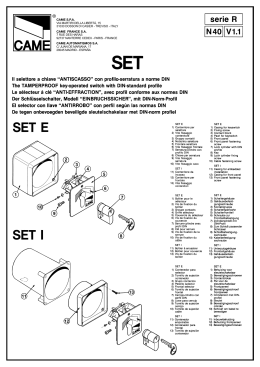
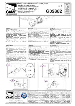
SERIE FLEX
Documentazione
Tecnica
| FLEX SERIES | SÊRIE FLEX | BAUREIHE FLEX | SERIE FLEX
S56
F 500 - F 510
rev. 2.0
del 01/04
©
CAME
CANCELLI
AUTOMATICI
119DS56
MOTORIDUTTORE PER L'AUTOMAZIONE DI CANCELLI PEDONALI E/O CARRABILI A BATTENTE
DI LARGHEZZA MASSIMA FINO A 1.60 m. PER ANTA
GEARMOTOR FOR POWERING PEDESTRIAN AND/OR DRIVEWAY GATES HAVING WINGS
WITH MAXIMUM WIDTH OF 1.60 m. EACH
MOTORÉDUCTEUR POUR L'AUTOMATISATION DE PORTAILS A BATTANT POUR PIETONS ET/OU VOITURES
AYANT UNE LARGEUR MAXIMALE DE 1.60 m. CHACUN
GETRIEBEMOTOR FÜR DEN ANTRIEB EINGANGS- UND/ODER EINFAHRTSTOREN
MIT EINER HÖCHSTBREITE VON 1.60 m. PRO TORFLÜGEL
MOTORREDUCTOR PARA LA AUTOMATIZACION DE PUERTAS PEATONALES Y/O CARRILES A HOJAS
BATIENTES DE LONGITUD MAXIMA DE HASTA 1.60 m. CADA HOJA
6
7
4
8
1
4
2
TX
RG58
3
5
2x1
3 x 1,5 / 230V
RX
4x1
2 x 1,5
Impianto tipo
Standard installation
Installation type
Standard Montage
Instalación tipo
2x1
9
2x1
* 2 x 1,5
*2 x 1,5
Cavi di alimentazione motori:
2 x 1.5 mm2 fino a 20 m
2 x 2.5 mm2 fino a 30 m
Power wires to motor:
2 x 1.5 mm2 up to 20 m
2 x 2.5 mm2 up to 30 m
Câbles d'alimentation moteur:
2 x 1.5 mm2 jusqu'à 20 m
2 x 2.5 mm2 jusqu'à 30 m
Antriebsmotor-Verbindungskabel:
2 x 1.5 mm2 bis 20 m
2 x 2.5 mm2 bis 30 m
Cables de alimentación motores:
2 x 1.5 mm2 hasta 20 m
2 x 2.5 "
" 30 m
Composizione set:
Set composition:
Composition set:
Das Montageset enthält:
Composición set:
123456789-
Gruppo motoriduttore
Quadro comando
Ricevitore radio
Fotocellule
Selettore esterno a
chiave
Lampeggiatore
Antenna
Elettroserratura
Trasmettitore
123456789-
Gear motor unit
Control panel
Radio receiver
Photocells
Protruding
key-operated selector
switch
Flasher
Antenna
Electric lock
Transmitter
1 - Groupe motoréducteur
2 - Armoire de commande
3 - Récepteur radio
4 - Photocellule
5 - Sélecteur externe a
clé
6 - Clignotant
7 - Antenne
8 - Serrure électrique
9 - Emetteur
123456789-
Antriebsmotor
Steuergerät
Funkempfänger
Photozellen
Außenmontage-Schlüsselschalter
Blinkleuchte
Antenne
Elektroschloß
Funksender
1 - Conjunto motorreductores
2 - Cuadro de mando
3 - Radioreceptor
4 - Fotocélules
5 - Selector exterior
mediante llave
6 - Lámpara
7 - Antena
8 - Cerradura eléctrica
9 - Trasmisor
ASSI & INGOMBRI | CENTRE LINES AND EXTERNAL DIMENSIONS | AXES ET ENCOMBREMENTS
ACHSEN & ABMESSUNGEN | EJES Y DIMENSIONES MÁXIMAS
F 500
i = 230 mm. max
con apertura a 90°
with 90° opening angle
avec ouverture à 90°
mit 90°-Öffnungwinkel
con apertura a 90°
C min
A= 40
B= 210
corsa=115
Disassamento minimo
Minimum misalignment
Excentration minimum
Min. Fluchtabweichung
Desalineado mínimo
C min.=0
LARGHEZZA ANTA
PESO ANTA
GATE WING WIDTH
GATE WING WEIGHT
LARGEUR VANTAIL
POIDS VANTAIL
TORFLÜGELBREITE
TORFLÜGELGEWICHT
ANCHO PUERTA
PESO PUERTA
m.
Kg.
0,80
150
1,20
125
1,60
100
A
C
40÷100
0÷150
B= 210
B= 235
C max
A= 100
corsa=350
Disassamento max.
Maximum misalignment
Excentration maximum
Max. Fluchtabweichung
Desalineado máximo
F 510
2
C max=150
B= 235
ASSI & INGOMBRI | CENTRE LINES AND EXTERNAL DIMENSIONS | AXES ET ENCOMBREMENTS
ACHSEN & ABMESSUNGEN | EJES Y DIMENSIONES MÁXIMAS
F500
Staffa di aggancio braccio snodato
Bracket articulated arm
Etriere de fixation du bras articulés
Armbefestigungs-Bügel
Estribo de enganche brazo articolados
5 x ø 8,5
56
17,5
12
50
80
56
2 x ø 6,5
12 20
Asse comune
Common centre line
Axe commun
Gemeinsame Achse
Eje común
Flangia attacco motoriduttore
Gear motor mounting flange
Bride de raccord du motoréducteur
Getriebemotorbefestigungs-Flansch
Brida anclaje motorreductor
80
F510
Guida di scorrimento braccio diritto
Travel guide for straight arm
Glissière de coulissement bras droit
Führungsschiene für geraden Arm
Guía de deslizamiento brazo recto
5 x ø 8,5
56
24
12
15 20
3 x M6
150
50
150
50
56
400
20
Flangia attacco motoriduttore
Gear motor mounting flange
Bride de raccord du motoréducteur
Getriebemotorbefestigungs-Flansch
Brida anclaje motorreductor
12
80
CARATTERISTICHE TECNICHE | TECHNICAL CHARACTERISTICS | CARACTERISTIQUES TECHNIQUES
TECHNISCHE DATEN | CARACTERISTICAS TECNICAS
MOTORIDUTTORE
GRADO DI
PROTEZIONE
PESO
GEARMOTOR
PROTECTION
RATING
WEIGHT
MOTORÉDUCTEUR
DEGRÉ DE
PROTECTION
GETRIEBEMOTOR
ALIMENTAZIONE
CORRENTE
MASSIMA
POTENZA MASSIMA
ASSORBITA
INTERMITTENZA
LAVORO
POWER SUPPLY
MAXIMUM
CURRENT
MAXIMUM POWER
CONSUMPTION
DUTY CICLE
POIDS
ALIMENTATION
COURANT
MAXIMALE
PUISSANCE MAXIMALE
ABSORBEE
INTERMITTENCE DE
TRAVAIL
SCHUTZGRAD
GEWICHT
STROM
VERSORGUNG
MAXIMAL
STROM
HÖCHST LEISTUNG
SAUFNAHME
EINSCHALTDAUER
MOTORREDUCTOR
GRADO DE
PROTECCION
PESO
ALIMENTACION
CORRIENTE
MAXIMA
POTENCIA MAXIMA
ABSORBIDA
INTERMITENCIA
TRABAJO
F500 - F510
IP 54
2,5 kg.
24 V d.c
2A
48 W
50 %
3
COPPIA
MASSIMA
MAXIMUM
TORQUE
COUPLE
MAXIMALE
HÖCHST
DREHMOMENT
PAREJA MOTOR
MAXIMA
10 daNm
RAPPORTO DI
RIDUZIONE
REDUCTION RATIO
RAPPORT DE
REDUCTION
UNTERSETZUNGS
VERHÄLTNIS
RELACION DE
REDUCCION
1/531
ISTRUZIONI DI MONTAGGIO | ASSEMBLY INSTRUCTIONS | INSTRUCTIONS POUR LE MONTAGE
MONTAGEANLEITUNG | INSTRUCCIONES DE MONTAJE
1) Tracciare gli assi e gli
ingombri dell’insieme
tenendo conto degli
schemi alle pag. 2 e
3, quindi fissare la
flangia di ancoraggio
del motoriduttore al
muro o al pilastro e, per
il motoriduttore F 500, il
supporto di ancoraggio
al cancello.
1) Trace the centre lines
and external dimensions
of the entire assembly
in accordance with the
diagrams on pages 2
and 3.
Next, mount the flange
for the gear motor on the
wall or pillar, and mount
the anchor block for gear
motor F500 on the gate.
1) Tracer les axes et
les encombres de
l’ensemble en se
référant aux schémas de
page 2 et 3, puis fixer la
bride du motoréducteur
au mur ou au pilier. Pour
le motoréducteur F500,
fixer le support de
fixation au portail.
1) Die Achsen und
Außenabmessungen
der
Antriebseinheit
unter Berücksichtigung
der schematischen Darstellungen auf Seite 2 und
3 aufreißen und dann den
Getriebe-motor-Flansch
an der Wand oder am
Pfosten befestigen und,
bei Verwedung des
Getrie-bemotor F500, die
entsprechende Befestigungsvorrichtung am Tor
anbringen.
F500
F510
2) Assemblare il braccio
snodato unendo i
due semibracci con
l’apposita bulloneria.
1) Trazar los ejes y
las dimensiones del
conjunto tenendo en
cuenta los esquemas
de pág. 2 y 3,posteriormente fijar la brida
del motorreductor a la
pared o al pilar y, para
el motorreductor F500,
el soporte de enclje a la
puerta.
2) Use the hardware
provided with the unit to
join the two halves of the
articulated arm together.
2) Assembler le bras
articulé en reliant les
deux demibras avec la
boulonnerie prèvue à
cet effet.
F500
4
2) Die beiden GelenKarmhälften mit den mitgelieferten Schrauben
zusammenfügen
2) Ensamblar el brazo
articulado uniendo
los semibrazos
con los pernos
correspondientes
3) Fissare la guida di 3) Secure the runner to
scorrimento all'anta the wing and insert the
e inserire il braccio straight arm.
dritto.
3) Fixer le rail de
guidage au vantail et
monter le bras droit.
3) Die Laufschiene am
Türflügel befestigen
und den geraden Arm
einführen.
3) Fije la guía de
deslizamiento a la hoja
e introduzca el brazo
recto.
F 510
4) Togliere la calotta 4) Remove the cover at 4) Enlever les carter 4) Die untere Getriebe- 4) Desplazar el casqueinferiore dal motoridut- the bottom of the gear inférieur du motoré- motor-Schutzabdeckung te inferior de la puerta.
tore.
ductéur.
motor.
entfernen.
5
5) Fissare il motoriduttore alla flangia
mediante le quattro viti
in dotazione.
- Fissare la calotta superiore.
5) Using the four screws
provided with the unit,
install the gear motor on
the flange.
- Fix the upper cap.
5) Fixer le
motoréducteur à la
bride à l’aide des
quatre vis fournies.
- Fixer la calotte
supérieure.
5) Den Getriebemotor
mit den vier zum
Lieferumfang gehörenden
Schrauben am Flansch
befestigen.
- Die obere Gehäusehälfte Befestigen.
5) Fijar el motor-reductor a la brida mediante los quatro tornillos suministrados.
- Fije la tapa superior.
ø 3,5 x 9,5
6) Assemblare il braccio snodato (A) alla
boccola intermedia
solidale all’albero del
motoriduttore;
- Fissare la staffa sul
cancello con l’apposita bulloneria;
- Eseguire il collegamento elettrico, dare
tensione al motoriduttore in chiusura e
fissare il braccio tramite il grano M6 (B);
- Fissare la calotta inferiore.
6) Assemble the articulated arm (A) onto the
intermediate bush which
is all in one with the ratiomotor shaft;
- Using the hardware
provided with the unit,
install the bracket on
the gate;
- Make the electrical connection, supply voltage
to the ratio-motor during
closure and secure the
arm with the M6 (B)
grub screw;
6) Assembler le bras
articulé (A) à la douille
intermédiaire solidaire de l’arbre du motoréducteur;
- Fixer l’étrier sur le
portail avec la boulon-nerie prévue à cet
effet ;
- Effectuer le branchement électrique,
donner de la tension
au motoréducteur en
fermeture et fixer le
bras à l’aide du boulon
sans tête M6 (B);
- Fixer la calotte inférieure.
A
F 500
B
ø 3,9 x 13
6
6) Den Gelenkarm (A)
an der mittleren Buchse
anbringen, die fest mit der
Welle vom Getriebemotor
verbun-den ist.
- Den Bügel mit den entsprechenden Schrauben
am Tor befestigen.
- Den Stromanschluß
durchführen, den Strom
am Getriebemotor beim
Schließen einschalten
und den Arm mit dem
Zapfen M6 (B) befestigen.
- Die untere Gehäusehälfte Befestigen.
6) Ensamble el brazo articulado (A) al
casquillo intermedio
integrado con el árbol
del motorreductor;
- Fijar el estribo a la
puerta con los tornillos correspondientes;
- Haga la conexión eléctrica, ponga bajo tensión el motorreductor
durante el cierre y
fije el brazo con el
pasador M6 (B);
- Fije la tapa inferior.
7)
Assemblare
il
braccio diritto (D) alla
boccola intermedia
solidale all’albero del
motoriduttore;
- Eseguire il collegamento elettrico, dare
tensione al motoriduttore in chiusura
e fissare il braccio
tramite i grani M8 (C)
e M4 (E);
- Fissare la calotta
inferiore.
7) Assemble the articulated arm (D) onto the
intermediate bush which
is all in one with the ratiomotor shaft;
- Make the electrical connection, supply voltage
to the ratio-motor during
closure and secure the
arm with the M6 (C)
grub screws;
- Fix the lower cap.
7) Assembler le bras
articulé (D) à la douille
intermédiaire solidaire de l’arbre du motoréducteur;
- Effectuer le branchement électrique,
donner de la tension
au motoréducteur en
fermeture et fixer le
bras à l’aide des boulons sans tête M6 (C);
- Fixer la calotte inférieure.
7) Den Gelenkarm (D)
an der mittleren Buchse
anbringen, die fest mit der
Welle vom Getriebemotor
verbun-den ist.
- Den Stromanschluß
durchführen, den Strom
am Getriebemotor beim
Schließen einschalten
und den Arm mit dem
Zapfen M6 (C) befestigen.
- Die untere Gehäusehälfte Befestigen.
7) Ensamble el brazo articulado (D) al
casquillo intermedio
integrado con el árbol
del motorreductor;
- Haga la conexión eléctrica, ponga bajo tensión el motorreductor
durante el cierre y fije
el brazo con las pasadores M6 (C);
- Fije la tapa inferior.
D
C
F 510
C
E
E
8) completare l’installazione fissando il coperchietto superiore con il
relativo OR.
8) Complete instal-lation by mounting the
upper cover with its
OR gasket.
8) Terminer l’instal-lation
en fixant le cou-vercle
supérieur avec le joint
torique correspon-dant.
F 500 - F 510
OR
7
8) Die Installation
beenden und die obere
Abdeckung mit entsprechender Rund-gummidichtung befe-stigen.
8) Completar la instalación fijando la tapa
superior con el correspondiente OR.
MANUTENZIONE - MAINTENANCE - ENTRETIENS - INSTANDHALTUNG - MANIMIENTO
Ingrassare periodicamente i perni di congiunzione dei bracci e, nel modello F510, gli elementi di scorrimento.
Regulary grease the junction pins on the arms. On model F510, regulary grease the sliding elements.
Graisser périodiquement les pivots de liaison des bras et, pour le modéle F510, les éléments coulissants.
Die Verbindungsstifte der Arme, bzw. bei Modell F510, die Gleitelmente regelmäßig schmieren.
Engrasar periódicamente los pernos de unión de los brazos y, en el modelo F510, los elementos deslizantes.
Tutti i dati riportati nel presente libretto
sono indicativi. La CAME s.p.a. si riserva di apportare eventuali modifiche
inerenti all'evoluzione tecnologica dei
prodotti.
All data mentioned in the present booklet
are for information only. CAME SPA
reserves the right to introduce changes
relating to technological improvements
of the products.
ASSISTENZA TECNICA
NUMERO VERDE
800 295830
CANCELLI AUTOMATICI
SISTEMA QUALITÅ
CERTIFICATO
WEB
www.came.it
E-MAIL
[email protected]
CAME CANCELLI AUTOMATICI S.P.A.
DOSSON DI CASIER (TREVISO)
(+39) 0422 4940
(+39) 0422 4941
Toutes les données mentionnées dans
le livret sont indicatives. CAME se réserve le droit d'apporter des modifications
éventuelles par rapport à l'évolution
téchnologique des produits.
Alle in der vorliegenden Beschreibung
angegebenen Daten dienen nur der
information. CAME S.P.A. behält sich
technische Andernungen vor.
CAME LOMBARDIA S.R.L._____COLOGNO M. (MI)
(+39) 02 26708293
(+39) 02 25490288
CAME SUD S.R.L. ___________________NAPOLI
(+39) 081 7524455
(+39) 081 7529109
CAME (AMERICA) L.L.C.________MIAMI (FL)
(+1) 305 5938798
(+1) 305 5939823
CAME AUTOMATISMOS S.A__________MADRID
(+34) 091 5285009
(+34) 091 4685442
CAME BELGIUM__________________LESSINES
(+32) 068 333014
(+32) 068 338019
8
Todos los datos de este libreto son
indicativos. CAME s.p.a. se reserva el
derecho de aportar las modificaciones
producidas por la evolución tecnológica de los productos.
CAME FRANCE S.A.____NANTERRE CEDEX (PARIS)
(+33) 01 46130505
(+33) 01 46130500
CAME GMBH________KORNTAL BEI (STUTTGART)
(+49) 07 15037830
(+49) 07 150378383
CAME GMBH____________SEEFELD BEI (BERLIN)
(+49) 03 33988390
(+49) 03 339885508
CAME PL SP.ZO.O______________WARSZAWA
(+48) 022 8365076
(+48) 022 8369920
CAME UNITED KINGDOM LTD___NOTTINGHAM
(+44) 0115 9210430
(+44) 0115 9210431
Scaricare