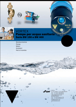
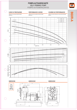
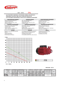
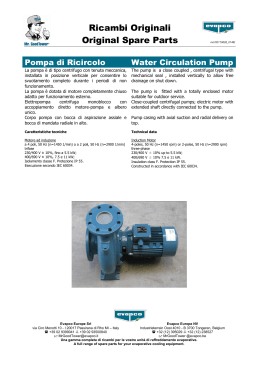
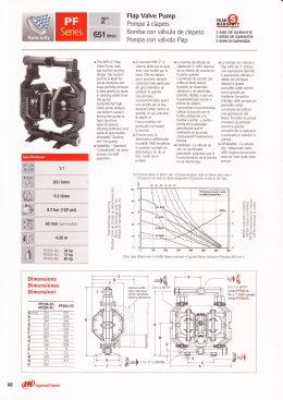
LRL-JRL Y 1200 JRL LRL INSTALLATION ET MISE EN SERVICE DES POMPES IN-LINE SIMPLES ET DOUBLES (PN10) FRANCAIS INSTALLATION AND STARTING INSTRUCTIONS OF SINGLE AND DUAL HEAD IN-LINE PUMPS (PN10) ENGLISH ISTRUZIONI DI MONTAGGIO E DI MESSA IN SERVIZIO DELLE POMPE IN-LINE SEMPLICI E DOPPIE (PN 10) ITALIANO INSTALACION Y PUESTA EN SERVICIO DE LAS BOMBAS IN-LINE SIMPLES Y DOBLES (PN10) ESPAÑOL N.M.S. N° STOCK N° 2037878/Ed.3/06.00 FRANCAIS DÉCLARATION ”CE” DE CONFORMITÉ AUX DIRECTIVES ”MACHINES” & ”COMPATIBILITÉ ÉLECTROMAGNÉTIQUE” POMPES SALMSON déclare que les matériels désignés dans la présente notice sont conformes aux dispositions des directives ”MACHINES” modifiée (Directive 89/392/CEE) et ”COMPATIBILITÉ ÉLECTROMAGNÉTIQUE” modifiée (Directive 89/336/CEE) et aux législations nationales les transposant. Ils sont également conformes aux dispositions des normes européennes harmonisées suivantes : EN 809 / EN 50.081-1 / EN 50.082-2 DEUTSCH EG-ERKLÄRUNG ZUR KONFORMITÄT MIT DER RICHTLINIE ”MASCHINEN” und ”ELEKTROMAGNETISCHE VERTRÄGLICHKEIT” Die Firma POMPES SALMSON erklärt, daß die in diesem vorliegenden bezeichneten Ausrüstungen die Bestimmungen der abgeänderten Richtlinie "MASCHINEN" (EG-Richtlinie 89/392) sowie die Bestimmungen der abgeänderten Richtlinie "ELEKTROMAGNETISCHE VERTRÄGLICHKEIT" (EG-Richtlinie 89/336) sowie die nationalen Vorschriften, in denen diese Richtlinien umgesetzt werden, einhalten. Sie stimmen ferner mit den Bestimmungen der folgendenvereinheitlichten europäischen Normen überein: EN 809 / EN 50.081-1 / EN 50.082-2 ENGLISH EC DECLARATION OF COMPLIANCE WITH THE "MACHINES" & "ELECTROMAGNETIC COMPATIBILITY" DIRECTIVES DANKS ERKLÆRING OM OVERENSSTEMMELSE MED EF’s “MASKINDIREKTIV” og “ELEKTROMAGNETISK KOMPATIBILITETSDIREKTIV” POMPES SALMSON declares that the equipment described in this manual complies with the provisions of the modified ”MACHINES” directive (Directive 89/392/EEC) and with the modified "ELECTROMAGNETIC COMPATIBILITY" directive (Directive 89/336/EEC) and with national enabling legislation based upon them. It also complies with the following European standards and draft standards: POMPES SALMSON erklærer, at udstyret, der beskrives i dette brugsanvisning, er i overensstemmelse med bestemmelserne i det ændrede “MASKINDIREKTIV” (Direktiv 89 / 392 / EØF) og det ændrede “ELEKTROMAGNETISK KOMPATIBILITETSDIREKTIV” (Direktiv 89 / 336 / EØF) samt de nationale lovgivninger, der indfØrer dem. Det er ligeledes i overensstemmelse med bestemmelserne i fØlgende forslag og harmoniserede europæiske standarder: EN 809 / EN 50.081-1 / EN 50.082-2 EN 809 / EN 50.081-1 / EN 50.082-2 ITALIANO DICHIARAZIONE DI CONFORMITA' "CE" ALLA DIRETTIVA "MACCHINE" & "COMPATIBILITA' ELETTROMAGNETICA" NEDERLANDS "EG" VERKLARING VAN CONFORMITEIT MET DE RICHTLIJN "MACHINES" EN "ELEKTROMAGNETISCHE COMPATIBILITEIT" La ditta POMPES SALMSON dichiara che i materiali descritti nel presente manuale rispondono alle disposizioni delle direttive "MACCHINE" modificate (Direttiva 89/392/CEE) e "COMPATIBILITA' ELETTROMAGNETICA" modificata (Direttiva 89/336/CEE) nonché alle legislazioni nazionali che le transpongono. Sono pure conformi alle disposizioni delle seguenti norme europee armonizzate: POMPES SALMSON verklaart dat het in deze document vermelde materieel voldoet aan de bepalingen van de gewijzigde richtlijnen "MACHINES" (Richtlijn 89/392/EEG) en "ELEKTROMAGNETISCHE COMPATIBILITEIT" (Richtlijn 89/336/EEG) evenals aan de nationale wetgevingen waarin deze bepalingen zijn overgenomen. Het materieel voldoet eveneens aan de bepalingen van de ontwerp-norm en de Europese normen: EN 809 / EN 50.081-1 / EN 50.082-2 EN 809 / EN 50.081-1 / EN 50.082-2 ESPAÑOL DECLARACIÓN "C.E." DE CONFORMIDAD CON LAS DIRECTIVAS "MÁQUINAS" Y "COMPATIBILIDAD ELECTROMAGNÉTICA" POMPES SALMSON declara que los materiales citados en el presente folleto están conformes con las disposiciones de la directiva "MÁQUINAS" modificada (Directiva 89/392/CEE) y "COMPATIBILIDAD ELECTROMAGNÉTICA" modificada (Directiva 89/336/CEE) y a las legislaciones nacionales que les son aplicables. También están conformes con las disposiciones de las siguientes normas europeas armonizadas: EN 809 / EN 50.081-1 / EN 50.082-2 PORTUGUÊS DECLARAÇÃO "C.E." DE CONFORMIDADE COM AS DIRECTIVAS "MÁQUINAS" E COMPATIBILIDADE ELECTROMAGNÉTICA POMPES SALMSON declara que os materiais designados no presente catálogo obedecem às disposições da directiva "MÁQUINAS", modificada (Directiva 89/392/CEE) e "COMPATIBILIDADE ELECTROMAGNÉTICA" (Directiva 89/336/CEE) e às legislações nacionais que as transcrevem. Obedecem igualmente às disposições das normas europeias harmonizadas seguintes: EN 809 / EN 50.081-1 / EN 50.082-2 ∂§§∏¡π∫A ¢∏§ø™∏ ¶I™Δ√Δ∏Δ∞™ ”EK” ¶ƒ√™ Δ∏¡ O¢∏°I∞ ™ÃEΔπCA ME TI™ ”MHXANE™” & ”Δ∏¡ ∏§EKTPOMA°NHTIKH ™YMBATOTHTA” H POMPES SALMSON ‰ËÁÒvÂÈ fiÙÈ ÔÈ ÂÍÔÁÈÛÌÔ› Ô˘ ·Ó·Ê¤ÚÔÓÙ·È fiÙÔÓ ·ÚfiÓ٠ηٿÁÔÁÔ Â›Ó·È Û‡ÌʈÓÔÈ Ì ÙȘ ‰È·Ù¿ÍÂȘ Ù˘ ÙÚÔÔÈË̤Ó˘ Ô‰ËÁ›·˜ Û¯ÂÙÈο ÌÂÙȘ ”MHXANE™” (O‰ËÁ›· 89/392/EOK) Î·È Ù˘ ÙÚÔÔÔÈË̤Ó˘ Ô‰ËÁ›·˜ Û¯ÂÙÈο Ì ÙËÓ ”Δ∏¡ ∏§EKTPOMA°NHTIKH ™YMBATOTHTA” (O‰ËÁ›· 89/336/EOK) ηıÒ˜ Î·È Ì ÙȘ ÂıÓÈΤ˜ ÓÔÌÔıÂۛ˜ Ô˘ ÂÍ·ÛÊ·Á›˙Ô‡Ó ÙËÓ ÚÔÛ·ÚÌÔÁ‹ ÙÔ˘˜. ∂›Ó·È ›Û˘ Û‡ÌʈÓÔÈ Ì ÙȘ ‰È·Ù¿ÍÂȘ ÙÔ˘ ۯ‰›Ô˘ Î·È ÙˆÓ ·ÎfiÁÔ˘ıˆÓ ÂÓ·ÚÌÔÓÈÛÌ¤ÓˆÓ Â˘Úˆ·˚ÎÒÓ ÚÔÙ‡ˆÓ : EN 809 / EN 50.081-1 / EN 50.082-2 QUALITY MANAGEMENT Robert DODANE FIG. 1 LRL LRL - JRL JRL FIG. 2 FIG. 3 150 min. 150 min. 43 5 Y1200 (JRL) 439 DS (LRL) U V W Z X Y 43 5 3-Ph. 400V- Y OPTION DN65 & 80 Z2 Z1 4Ø14 Y1200 (JRL) 439 DS (LRL) 410 365 Y X U V W Z X Y 3Ø14 FIG. 5 DN X mm Y mm Z1 mm Z2 mm 65 80 210 250 260 300 264 312 190 230 310 228 6 3-Ph. 230V- JRL FIG. 4 ou LRL 3-Ph. 230V or 3-Ph. 400V N L1 L2 L3 N L1 L2 L3 L1 L2 L3 1 3 5 13 2 4 6 14 1 2 3 4 Y1200 2 4 6 2 4 6 439D 98 97 96 95 2 4 6 D1 U V W U V W U Z X Y MOT. 1 Z X V W X Y Y MOT. 2 Z 3 D2 FRANCAIS - Montage direct sur tuyauterie possible dans toutes les directions sauf moteur vers le bas (voir FIG.1). 1. GÉNÉRALITÉS 1.1 Applications Pour tout pompage de liquides clairs chimiquement neutres, sans particules abrasives en suspension. • Chauffage central. • Conditionnement d’air. • Circuit eau glacée. • Boucle d’eau chaude sanitaire. • Transfert d’eau... 1.2 Caractéristiques techniques • Pression de service maxi • Plage de température • Brides asp. refoul. à portée de joint Le montage de la pompe JRL sur une tuyauterie horizontale, axes moteurs horizontaux, implique une permutation périodique des pompes pour éviter la formation de poche d’air en point haut du corps. - Montage sur massif avec socle support pompe (option DN65 et 80) avec fixation par boulons de scellement (plan de pose voir FIG.2). - Le volume du massif devra être en rapport avec le poids et les dimensions de la pompe. - Si l’installation comporte plusieurs pompes, leur montage peut être réalisé sur un massif commun. - Prévoir sous le massif de béton un matériau isolant (liège ou caoutchouc armé) pour éviter les vibrations. : 10 bars : < 10 ° à + 110 °C : (NFE 29203) ISO PN10 2. SÉCURITÉ La présente notice devra être lue avec attention avant installation et mise en service. On veillera en particulier, au respect des points concernant la sécurité du matériel vis à vis de l’utilisateur intermédiaire ou final. 5.2 Raccordements hydrauliques Par contre-brides rondes à souder PN10 (non fournies) de même diamètre que les orifices. - Raccorder à la pompe les tuyauteries aspiration refoulement équipées de contre-brides (en option) PN10 à portée de joint. Respecter le sens d’écoulement (voir flêches sur les brides) du corps de pompe. • Prévoir de part et d’autre des orifices des vannes d’isolement pour faciliter le démontage de la pompe et des manchettes antivibratoires pour éviter les contraintes et la transmission des bruits de circulation. 2.1 Symboles des consignes du manuel Mise en garde. Consignes relatives à l’électricité. Appelle l’attention sur un risque potentiel, ATTENTION ! mettant en danger la sécurité des personnes. JRL : Monter après la bride de refoulement une manchette ou un divergent avant la vanne d’isolement, pour permettre une intervention sur le clapet sans démonter la pompe. 3. TRANSPORT ET STOCKAGE Dès réception du matériel, vérifier s’il n’a pas subi de dommages durant son transport. En cas de défaut constaté, prendre dans les délais prévus toutes dispositions nécessaires auprès du transporteur. Mesures de pression : deux orifices diamètre 1/8” de raccordement de manomètres sont prévus sur les brides aspiration et refoulement. 5.3 Raccordements électriques Si le matériel livré devait être installé ultérieurement, stockez-le dans un endroit sec et protégez-le contre les chocs et toutes influences extérieures (humidité, gel, etc...). Les raccordements électriques et les contrôles doivent être effectués par un électricien agréé et conformément aux normes locales en vigueur. 4. PRODUITS ET ACCESSOIRES • Protection des moteurs : - LRL : par discontacteur 439D - JRL: par coffret Y 1200, permettant en plus la permutation des pompes. 4.1 La pompe Monobloc, centrifuge, monocellulaire LRL : Modèle simple JRL: Modèle double avec clapet anti-retour au refoulement assurant la permutation hydraulique des 2 pompes. Les orifices aspiration-refoulement sont IN-LINE (en ligne) sur le même axe. Réseau d’alimentation • Utiliser un câble d’alimentation à 4 conducteurs (3 phases + terre) pour raccorder le réseau TRI 230 V ou TRI 400 V aux bornes du moteur SANS oublier la borne terre (voir FIG.3). Le moteur à bout d’arbre allongé, est équipé d’une protection intégrée par sondes ipsothermiques. Les roulements sont garnis d’une graisse à haute performance assurant leur lubrification pour la durée de vie du moteur. Vitesse : 1450 ou 2900 tr/mn Bobinage TRI : 230-400 V Fréquence : 50 Hz Classe d’isolation :F Indice de protection : IP54 Le câble ne devra jamais être en contact ni avec la tuyauterie ni avec la pompe. Sonde ipsothermique (une par moteur) Raccordement obligatoire. Le circuit électrique s’ouvre sur échauffement anormal du bobinage (démarrages fréquents, surcharges...) et se referme automatiquement dès que la température redevient normale. Le réarmement manuel s’effectue sur le bouton du discontacteur (439D) ou sur le bouton intégré dans le coffret Y 1200. L’étanchéité au passage de l’arbre est assurée par une garniture mécanique auto-lubrifiée, sans entretien, à faces de friction : Carbone/carbure de silicium/joint E.P. Schémas électriques de raccordement sur le discontacteur (439D) ou sur le coffret Y 1200, fournis avec les coffrets (ou voir FIG.4 et FIG.5). 4.2 Accessoires En supplément on peut commander : • Discontacteur (LRL) • Coffret de commande Y 1200 (JRL) • Contre-brides rondes à souder PN10 • Vannes d’isolement • Manchettes anti-vibratoires • Couvercle d’obturation (JRL) • Kit de prise de pression • Socle pour modèles DN65 et 80 • 6. MISE EN ROUTE 6.1 Remplissage - Dégazage Ne jamais faire fonctionner la pompe à sec, même un court instant. 5. INSTALLATION 5.1 Montage Installer la pompe dans un endroit facilement accessible et protégé du gel. La pompe peut être raccordée directement sur la tuyauterie ou installée sur un massif en béton. - Fermer la vanne au refoulement et remplir complètement la pompe et la tuyauterie d’aspiration. - Ouvrir le ou les purgeurs situés sur les lanternes-paliers et attendre que l’eau s’écoule franchement avant de refermer. 4 FRANCAIS 6.2 Réglages Si un incident de fonctionnement venait à persister, nous vous recommandons de vous adresser au SAV SALMSON ou à notre réseau de réparateurs agréés, seuls habilités à procéder au démontage-remontage de nos matériels (liste sur simple demande). Relais thermiques Régler sur le discontacteur 439D ou sur le coffret Y 1200 les relais thermiques de protection moteur suivant l’intensité plaquée. Procéder à un réglage précis : - Moteur à l’arrêt, couper une phase, - Remettre sous tension et s’assurer de la disjonction instantanée, - Vérifier si l’intensité absorbée est inférieure ou égale à celle indiquée sur la plaque moteur. - Ouvrir progressivement la vanne au refoulement et contrôler la stabilité de la pression. 8.1 LA POMPE NE DÉBITE PAS a) Relais thermique de protection mal réglé ou déclenché : - Vérifier son réglage suivant l’intensité plaquée sur le moteur ou réarmer le contacteur en enfonçant le bouton inférieur. b) Bobinage du moteur défectueux : - Déconnecter la boîte à bornes du moteur concerné et mesurer les résistances du bobinage. Contrôle du sens de rotation Le contôle du sens de rotation devra être de courte durée pour ne pas faire fonctionner longtemps la pompe à débit nul (vanne au refoulement fermée). Celui-ci est indiqué par une flèche située sur la lanterne palier. c) Fusibles défectueux ou “grillés” : - Vérifier leur calibrage, remplacer si nécessaire. d) Déclenchement de la sonde de protection moteur : - Vérifier la puissance ou l’intensité absorbée par le moteur. Réarmer le contacteur en enfonçant le bouton intérieur sur le coffret Y 1200 ou le bouton extérieur sur le coffret 439D. LRL + Discontacteur 439D : - Mettre sous tension le discontacteur et contrôler le sens correct de rotation du moteur. JRL + Coffret Y 1200 : - Mettre sous tension le coffret (voyant allumé) - Enfoncer les 2 touches “Marche manuelle et Marche pompe 1” (voyant allumé) - Vérifier le sens de rotation - Opérer de la même manière avec la pompe 2 8.2 LES PERFORMANCES HYDRAULIQUES NE SONT PAS ATTEINTES En cas d’inversion, croiser 2 fils de phase de l’alimentation au bornier du moteur concerné (ou aux bornes du discontacteur). - Ouvrir progressivement la vanne au refoulement et contrôler la stabilité de la pression. b) Vanne d’isolement fermée ou partiellement fermée : - Ouvrir la vanne progressivement jusqu’à complète stabilité de la pression. a) La pompe tourne en sens contraire : - Vérifier le branchement électrique et inverser deux fils de phase au bornier moteur (ou aux bornes du discontacteur, ou de l’armoire...). c) Le moteur est alimenté à une tension suffisante : - Vérifier la tension du courant d’alimentation (câbles de faible section - chute en ligne). 6.3 Fonctionnement Arrêt normal - Fermer la vanne au refoulement et arrêter la pompe. 8.3 MARCHE BRUYANTE DE LA POMPE Arrêt prolongé - Fermer les deux vannes d’isolement de la pompe et vidanger le corps de pompe si nécessaire (par le ou les bouchons prévus sur certaines pompes). - A la remise en route, s’assurer que les moteurs tournent librement sans points durs, remplir la pompe et la tuyauterie d’aspiration. - Purger la garniture mécanique. a) Poche d’air dans la pompe : - Purger la pompe à l’aide du purgeur manuel jusqu’à sortie d’eau, le refermer ensuite. - Vérifier la présence éventuelle d’un corps étranger. COUVERCLE D’OBTURATION AVEC JOINT POUR JRL Obture l’orifice de la pompe retirée pendant le dépannage. Le fonctionnement sans arrêt de l’installation est assuré par la mise en service de la pompe de secours. 7. ENTRETIEN Aucun entretien particulier en cours de fonctionnement. Maintenir la pompe en parfait état de propreté. Modèles Fréquences de remplacement Remarque : Il ne peut s’agir que de recommandations, la fréquence de remplacement est liée aux conditions de service du groupe : - Qualité, température et pression du liquide véhiculé pour la garniture mécanique, - Charge et température ambiante pour le moteur et les autres composants. Pièces ou composant Durée de vie de sujets à usure fonctionnement Garniture mécanique Roulements moteur Bobinage stator 10 000 heures MINI Fréquences de remplacement Service 15 H/JOUR continu 9 MOIS/AN 1 an 1,5 an 15 000 à 30 000 heures 2 ans 3 ans 25 000 heures 3 ans 4 à 5 ans Réf. commandes JRL tous types 30 908 178 F JRL 204-09 / 204-11 / 205-11 / 405-11 30 925 165 P JRL 206-12 / 208-12 30 925 166 Y SOCLE SUPPORT POMPE Tous modèles DN 65 et 80 Modèles 8. INCIDENTS DE FONCTIONNEMENT CAUSES ET REMÈDES Avant toute intervention METTRE HORS TENSION ATTENTION ! les pompes. 5 Réf. commandes LRL 206-12 30 925 701 Y LRL 406-12 à 406-15 LRL 408-15 / 208-12 30 925 700 P JRL 206-12 / 208-12 / 408-15 JRL 406-12 à 406-15 30 925 702 G ENGLISH The pump may be connected directly to the pipe or installed on a concrete foundation block. - Direct mounting on the pipe is possible in all positions except motor down (see FIG. 1). 1. GENERAL 1.1. Applications To pump all clear, chemically neutral liquids not containing abrasive particles in suspension. • Central heating. • Air conditioning. • Ice water circuit. • Secondary hot water loop. • Water transfer, etc. 1.2. Specifications • Max. service pressure • Temperature • Suction and discharge flanges with gasket contact faces If the JRL pump is installed on a horizontal pipe, with the motor centrelines horizontal, it will be necessary to switch operation between the pumps from time to time to avoid the formation of an air pocket at the high point of the casing. - Installation on foundation with pump baseplate (ND65 and 80 option) and attachment by anchor bolts (see FIG. 2 for installation). - The volume of the foundation block must be commensurate with the weight and size of the pump. - If there are several pumps in the installation, they can be installed on the same foundation. - Place an insulating material (reinforced rubber or cork) under the foundation block to cut down vibrations. : 10 bar : -10 to +110°C : ISO PN 10 (NF E 29203) 2. SAFETY Read this data sheet carefully before installing and starting up. Pay special attention to the points concerning the safety of the equipment for the intermediate or end user. 5.2. Hydraulic connections By PN10 weld-on round counter-flanges (not supplied) matching the diameter of the ports. - Connect the suction and discharge pipes, with the (optional) PN 10 counter-flanges with gasket contact faces, to the pump. 2.1. Symbols used in the manual Warning Note the direction of flow of the pump casing (look at the arrows on the flanges). Instruction concerning electricity • Place isolating valves after both ports to facilitate removal of the pump and anti-vibration sleeves and cut down stresses and circulation noise. Calls attention to a potential risk that might ATTENTION ! affect safety. 3. TRANSPORT AND STORAGE JRL: After the discharge flange, fit a sleeve or a diffuser before the isolating valve to allow work on the nonreturn valve without removing the pump (200 m long). When taking delivery of the equipment, check that it has not been damaged in transit. If anything is found wrong, take the necessary steps with the carrier within the allowed time. Pressure measurements: there are two 1/8” dia. ports on the suction and discharge flanges for connection of pressure gauges. If the equipment delivered is to be installed at a later time, store it in a dry place and protect it from impacts and outside influences (moisture, frost, etc.). 5.3. Electrical connections The electrical connections and checks must be made by a licensed electrician and comply with applicable local standards. 4. PRODUCTS AND ACCESSORIES • Protection of motors: - LRL, by a 439D circuit-breaker - JRL, by a Y1200 control box, which also allows automatic switching between thepumps. 4.1. The pump Monobloc, centrifugal, single-stage LRL : Single model JRL : Dual model with nonreturn valve on discharge to allow switching between two pumps. Power supply • Use a four-conductor cable (three phases + earth) to connect 230- or 400-V three-phase line power to the terminals of the motor; DO NOT forget the earth terminal (see FIG. 3). The suction and discharge ports are IN LINE. The motor, with a lengthened shaft end, has built-in protection by a thermal overload probe. The bearings are packed with a high-performance grease and lubricated for the life of the motor. Speed : 1450 or 2900 rpm Winding : for 230/400-V three-phase power Frequency : 50 Hz Insulation class :F Protection index : IP54 The power cable must not touch the pipe or the pump. Thermal overload probe (one per motor) Must be connected. Overheating of the winding (because of frequent starting, overloads, etc.) causes the electrical circuit to open; it closes automatically when the temperature returns to normal. The shaft has a maintenance-free self-lubricating mechanical seal with carbon/silicon carbide/drinking water gasket friction faces. The unit can be reset manually using the pushbutton on the circuitbreaker (439D) or the pushbutton incorporated in the Y1200 control box. Electrical diagrams showing the connection to the circuit-breaker (439D) or to the Y1200 control box are supplied with the units (or see FIGS. 4 and 5). 4.2. Accessories The following are available for an extra charge: • Circuit-breaker (LRL) • Y1200 control box (JRL) • Weld-on round counter-flanges, PN 10 • Isolating valves • Anti-vibration sleeves • Blanking cover (JRL) • Pressure gauge kit • Baseplate for ND 65 and 80 models 6. STARTING UP 6.1. Filling, degassing Never operate the pump dry, even momentarily. - Close the discharge valve and completely fill the pump and the suction pipe. - Open the bleed(s) on the bearing cages and wait for a steady stream of water to flow out before closing. 5. INSTALLATION 5.1. Installation Install the pump in a place that is easy to reach and protected from frost. 6 ENGLISH 6.2. Adjustments 8.1. NO DELIVERY FROM PUMP Thermal relays On the 439D circuit-breaker or the Y1200 control box, adjust the thermal relays protecting the motor according to the current marked on the data plate. a) Thermal protection relay incorrectly adjusted or tripped: - Check its setting against the current marked on the motor data plate or reset the circuit-breaker by pressing the pushbutton at the bottom. Carry out a fine adjustment: - With the motor stopped, disconnect one phase. - Power back up and check that the relay trips out immediately. - Check that the current drawn does not exceed the value marked on the motor data plate. - Gradually open the discharge valve and check the stability of the pressure. b) Motor winding faulty: - Disconnect the terminal box of the motor in question and measure the winding resistance values. c) Fuses defective or blownm: - Check their ratings and replace if necessary. d) Tripping of motor protection probe: - Check the power consumption or current draw of the motor. Reset the circuit-breaker by pressing the pushbutton on the bottom of the Y1200 control box or on the outside of the 439D control box. Check of direction of rotation The direction of rotation must be checked rather rapidly so as not to operate the pump in the no-flow condition (with the discharge valve closed) for too long. The correct direction is indicated by an arrow on the bearing cage. 8.2. HYDRAULIC PERFORMANCE DEFICIENT LRL + 439D circuit-breaker - Close the circuit-breaker and check that the motor turns in the right direction. a) The pump turns the wrong direction: - Check the electrical connections and reverse two phase wires on the terminal block of the motor (or on the terminals of the circuitbreaker, or of the control cabinet, etc.). JRL + Y1200 control box - Switch the box on (indicator lit). - Press the “Manual operation” and “Pump 1 on” pushbuttons (indicator lit). - Check the direction of rotation. - Perform the same operation for pump 2. b) Isolating valve closed or partially closed: - Open the valve gradually until the pressure is completely stabilized. c) Voltage of power supply to motor: - Check the power supply voltage (small cables in the circuit may cause a voltage drop in the line). If the pump turns in the wrong direction, interchange two power supply wires on the terminal block of its motor (or on the terminals of the circuit-breaker). - Gradually open the discharge valve and check pressure stability . 8.3. PUMP OPERATION IS NOISY a) Air pocket in pump: - Bleed the pump using the hand bleed device until water flows out, then close. - Check for the presence of a foreign body. 6.3. Operation Normal stop - Close the discharge valve and stop the pump. Prolonged shutdown - Close both isolating valves of the pump and if necessary drain the pump casing (through the plug(s) provided on certain pumps). - When restarting, make sure that the motors turn freely, without sticking; fill the pump and the suction pipe. - Bleed the mechanical seal. BLANKING COVER WITH GASKET FOR JRL Blanks the port of the pump removed for troubleshooting. The backup pump is started to ensure uninterrupted operation of the installation. 7. MAINTENANCE Model Order no. No special servicing in operation. Keep the pump perfectly clean. Replacement frequencies Remark: These are necessarily only guidelines, since the replacement frequency depends on the operating conditions: - Quality, temperature, and pressure of the liquid pumped for the mechanical seal; - Load and ambient temperature for the motor and other components. Mechanical seal Operating life Continuous duty 15 h/day 9 months/year At least 10,000 hours 1 year 1.5 year Motor bearing 15,000 to 30,000 hours 2 years 3 years Stator winding 25,000 hours 3 years 4 to 5 years 30 908 178 F JRL 204-09 / 204-11 / 205-11 / 405-11 30 925 165 P JRL 206-12 / 208-12 30 925 166 Y PUMP BASEPLATE Replacement frequency Parts or components subject to wear JRL all types for ND 65 and 80 models Model 8. OPERATING TROUBLE Order no. LRL 206-12 30 925 701 Y LRL 406-12 to 406-15 LRL 408-15 / 208-12 30 925 700 P JRL 206-12 / 208-12 / 408-15 JRL 406-12 to 406-15 30 925 702 G CAUSES AND REMEDIES Switch the pumps OFF before doing any work on ATTENTION ! them. 7 ITALIANO plinto di cemento armato. - Montaggio diretto su tubazioni possibile in tutte le direzioni salvo con il motore in basso (vedi Fig. 1). 1. OSSERVAZIONI GENERALI 1.1 Applicazioni Pompe destinate al pompaggio di liquidi chiari, chimicamente neutri, esenti da particelle abrasive in sospensione. • Riscaldamento centrale. • Condizionamento d'aria. • Circuiti di acqua ghiacciata. • Circuiti in loop di acqua calda sanitaria. • Trasporti d’acqua... Il montaggio della pompa JRL su una tubazione orizzontale con assi di motori orizzontali, implica una permuta periodica delle pompe allo scopo di evitare la formazione di sacche d’aria nel punto alto del corpo. - Montaggio su plinto con supporto pompa (opzione DN65 e 80) con fissaggio mediante bulloni ad immuratura (disegno di posa, vedi Fig. 2). - Il volume del plinto deve essere commisurato al peso e alla dimensione della pompa. - Se l’installazione comporta più pompe, il loro montaggio può essere realizzato su un plinto di fondazione comune. - Prevedere sotto il plinto di cemento armato un materiale isolante (sughero o gomma armata) per eliminare le vibrazioni. 1.2 Caratteristiche tecniche • Pressione di servizio massima : 10 bar : < 10 ° à + 110 °C • Campo di temperatura • Flange aspirazione e mandata. a portata di giunto : (NFE 29203) ISO PN10 2. SICUREZZA Le presenti istruzioni vanno lette attentamente prima di procedere all'installazione e alla messa in servizio. Verificare in particolare l'osservanza dei punti riguardanti la sicurezza del materiale per l'utente intermedio o finale. 5.2 Collegamenti idraulici Mediante controflange rotonde da saldare PN10 (non fornite) dello stesso diametro degli orifizi. - Collegare alla pompa le tubazioni aspirazione e mandata dotate di controflange (opzionali) PN10 a portata di giunto. Rispettare il senso del flusso (vedere le frecce riportate sulle flange) del corpo di pompa. • Prevedere su entrambi i lati degli orifizi delle valvole di isolamento per facilitare lo smontaggio della pompa e dei manicotti antivibrazione in modo da evitare le sollecitazioni e la trasmissione dei rumori di circolazione. 2.1 Simboli delle istruzioni del manuale Segnale di pericolo. Consegne relative all'elettricità. Richiama l'attenzione su di un rischio potenziale ATTENZIONE per la sicurezza delle persone. JRL: Montare dopo la flangia della mandata un manicotto o un divergente prima della valvola di isolamento per consentire l’intervento sulla valvola senza dover smontare la pompa. 3. TRASPORTO E IMMAGAZZINAMENTO Al ricevimento del materiale, verificare che esso non abbia subito danni durante il trasporto. Se dovessero essere constatati difetti, prendere in tempo utile le disposizioni necessarie nei confronti del vettore. Misura della pressione: due orifizi diametro 1/8” di collegamento dei manometri sono previsti sulle flange aspirazione e mandata. 5.3 Collegamenti elettrici Se il materiale così consegnato dovesse essere installato successivamente, immagazzinarlo in luogo asciutto e protetto dagli urti e da ogni influenza esterna (umidità, gelo, ecc.). I collegamenti elettrici ed i controlli vanno effettuati da un elettricista autorizzato in conformità alle vigenti norme locali. 4. PRODOTTI ED ACCESSORI • Protezione dei motori: - LRL : mediante discontattore 439D - JRL: mediante scatola Y1200, che consente inoltre la permuta delle pompe. 4.1 La pompa Monoblocco, centrifuga e monostadio LRL : Modello semplice JRL: Modello doppio con valvola di non ritorno sulla mandata che garantisce la permuta idraulica delle due pompe. Gli orifizi aspirazione mandata sono in-line sul medesimo asse. Rete di alimentazione • Utilizzare un cavo di alimentazione a 4 conduttori (3 fasi + terra) per collegare la rete TRI 230 V o TRI 400 V ai morsetti del motore SENZA dimenticare il morsetto di terra (vedi fig. 3). Il motore a estremità d’albero allungata è munito di una protezione integrata mediante sonde ipsotermiche. I cuscinetti sono lubrificati con grasso ad alte prestazioni che ne garantisce la lubrificazione per tutta la durata di vita del motore. Velocità Avvolgimento trifase Frequenza Classe d’isolamento Indice di protezione Il cavo non deve mai trovarsi a contatto né con la tubazione né con la pompa. : 1450 o 2900 tr/mn : 230-400 V : 50 Hz :F : IP54 Sonda ipsotermica (una per motore) Collegamento obbligatorio. Il circuito elettrico si apre ad un riscaldamento anormale dell’avvolgimento (avvii frequenti, sovraccarichi, ecc.) e si richiude automaticamente non appena la temperatura ritorna ad un valore normale. la tenuta stagna al passaggio dell’albero è garantita da una guarnizione meccanica autolubrificata a faccette di attrito, che non richiede manutenzione: Carbone/carburo di silicio/guarnizione EP Il riarmo manuale si effettua tramite il pulsante del discontattore (439D) o il pulsante integrato nella scatola Y 1200. Schemi elettrici di collegamento sul discontattore (439D) o sulla scatola Y 1200, forniti con le scatole (oppure vedere Fig. 4 e Fig. 5). 4.2 Accessori Possibilità di ordinare in supplemento: • Discontattori (LRL) • Scatola di comando Y 1200 (JRL)• Controflange rotonde da saldare PN10 • Valvole di isolamento • Manicotti antivibrazioni • Coperchio di otturazione (JRL) • Kit di presa di pressione • Zoccolo per modello DN65 e 80 • 6. AVVIAMENTO 6.1 Riempimento - Degasaggio La pompa non deve mai funzionare a secco, neanche per un breve istante. 5. INSTALLAZIONE 5.1 Montaggio Installare la pompa in un luogo facilmente accessibile e protetto dal gelo. La pompa può essere installata direttamente sulla tubazione o su - Chiudere la valvola di mandata e riempire completamente la pompa e la tubazione di aspirazione. - Aprire il o i depuratori che si trovano sulle lanterne-supporti ed aspettare che l'acqua sgorghi bene prima di richiuderla. 8 ITALIANO 6.2 Regolazione 8.1 LA POMPA GIRA SENZA EROGARE Relè termici Regolare sul discontattore 439D o sulla scatola Y1200 i relè termici di protezione motore secondo l’intensità indicata sulla targa. Procedere ad una regolazione precisa: - Con il motore spento, interrompere una fase, - Rimettere la tensione e verificare che l’interruzione sia istantanea, - Verificare che l’intensità assorbita sia inferiore o uguale a quella indicata sulla targhetta del motore. - Aprire progressivamente la valvola di mandata e controllare la stabilità della pressione. a) Relè termico di protezione mal regolato o disinserito: - Verificare la regolazione secondo l’intensità indicata sulla targa del motore o riarmare il contattore schiacciando il pulsante inferiore. Controllo del senso di rotazione Il controllo del senso di rotazione dovrà essere rapido per non far funzionare a lungo la pompa con erogazione zero (valvola di mandata chiusa). Il senso della rotazione motore è indicato da una freccia sulla lanterna supporto. d) Disinserimento della sonda di protezione motore: - Verificare la potenza o l’intensità assorbita dal motore. Riarmare il contattore schiacciando il pulsante interno della scatola Y 1200 o il pulsante esterno sulla scatola 439D. LRL + Discontattore 439D : - mettere in tensione il discontattore e controllare che il senso di rotazione del motore sia quello giusto. a) Il motore gira in senso contrario: - verificare l’allacciamento elettrico e invertire i due fili di fase sulla morsettiera motore (o sui morsetti del discontattore, o dell’armadio). b) Avvolgimento del motore difettoso: - Scollegare la morsettiera del motore interessato e misurare le resistenze dell’avvolgimento. c) Fusibili difettosi o fulminati: - Verificare la taratura e se del caso, sostituire. 8.2 LE PRESTAZIONI IDRAULICHE NON VENGONO RAGGIUNTE JRL + Scatola Y 1200 : - Mettere la cassetta sotto tensione (spia accesa). - Premere i due tasti “marcia manuale e marcia pompa 1” (con la spia accesa). - Verificare il senso di rotazione. - Procedere analogamente con la pompa 2 b) Valvola di isolamento chiusa o parzialmente chiusa: - Aprire la valvola progressivamente fino alla completa stabilità della pressione. c) La tensione di alimentazione del motore è insufficiente: - Verificare la tensione della corrente di alimentazione (sezione insufficiente dei cavi - caduta in linea). In caso di inversione, incrociare 2 fili di fase dell’alimentazione sulla morsettiera del motore interessato (o ai morsetti del discontattore). - Aprire progressivamente la valvola sulla mandata e controllare la stabilità della pressione. 8.3 RUMOROSITÀ DELLA POMPA a) Sacche d’aria nella pompa: - Spurgare la pompa mediante il depuratore manuale fino alla fuoriuscita d’acqua. Quindi richiuderla. - Verificare l’eventuale presenza di un corpo estraneo. 6.3 Funzionamento Arresto normale - Chiudere la valvola sulla mandata e arrestare la pompa. Arresto prolungato - Chiudere le due valvole di isolamento della pompa e svuotare il corpo della pompa se necessario (attraverso il o i tappi previsti su alcune pompe). - Alla rimessa in marcia, verificare che i motori girino liberamente senza resistenze, riempire la pompa e la tubazione di aspirazione. - Spurgare la guarnizione meccanica. Coperchio di otturazione con giunto per JRL Ottura l’orifizio della pompa rimossa durante la riparazione del guasto. Il funzionamento continuo dell’impianto è assicurato dalla messa in servizio della pompa di scorta. Modelli Riferimento ordine 7. MANUTENZIONE JRL tutti i tipi 30 908 178 F Non occorre alcuna manutenzione durante il funzionamento. Mantenere la pompa in perfetto stato di pulizia. JRL 204-09 / 204-11 / 205-11 / 405-11 30 925 165 P JRL 206-12 / 208-12 30 925 166 Y Frequenze di sostituzione Nota : Si tratta solo di raccomandazioni. La frequenza di sostituzione è legata alle condizioni di esercizio del gruppo: - Qualità, temperatura e pressione del liquido convogliato per la guarnizione meccanica, - Carico e temperatura ambiente per il motore e gli altri componenti. Modelli Frequenze di sostituzione Parti o componenti Durata di vita di soggetti a usura funzionamento Esercizio continuo 15 ore/giorno 9 mesi/anno Guarnizione meccanica 10 000 ore minimo 1 anno 1,5 anni Cuscinetto motore 15 000 a 30 000 ore 2 anni 3 anni 25 000 ore 3 anni 4 - 5 anni Avvolgimento statore Zoccolo supporto pompa Tutti i modelli DN 65 e 80 8. INCIDENTI DI FUNZIONAMENTO CAUSE E RIMEDI ATTENZIONE prima di procedere ad un intervento, DISINSERIRE le pompe. 9 Riferimento ordine LRL 206-12 30 925 701 Y LRL 406-12 a 406-15 LRL 408-15 / 208-12 30 925 700 P JRL 206-12 / 208-12 / 408-15 JRL 406-12 a 406-15 30 925 702 G ESPAÑOL hielo. La bomba puede conectarse directamente sobre la tubería o instalarse sobre un macizo de hormigón. - Montaje directo sobre tubería posible en todas las direcciones salvo con el motor hacia abajo (ver FIG. 1). 1. GENERALIDADES 1.1 Aplicaciones Para todo bombeo de líquidos claros químicamente neutros, sin partículas abrasivas en suspensión. • Calefacción central. • Acondicionamiento de aire. • Circuito de agua helada. • Bucle de agua caliente sanitaria. • Transferencia de agua... 1.2 Características técnicas • Presión de servicio máxima • Margen de temperatura • Bridas asp. desc. a apoyo de junta El montaje de la bomba JRL sobre una tubería horizontal, con los ejes motores horizontales, implica una permutación periódica de las bombas para evitar la formación de bolsones de aire en punto alto del cuerpo. - Montaje sobre macizo con placa de apoyo soporte de bomba (opción DN65 y 80) con fijación por pernos de anclaje (plano de colocación ver FIG.2). - El volumen del macizo deberá estar en relación con el peso y las dimensiones de la bomba. - Si la instalación incluye varias bombas, su montaje puede realizarse sobre un macizo común. - Prever bajo el macizo de hormigón un material aislante (corcho o goma armados) para evitar las vibraciones. : 10 bares : < 10 ° a + 110 °C : (NFE 29203) ISO PN10 2. SEGURIDAD El presente folleto deberá leerse atentamente antes de proceder al montaje y a la puesta en servicio. Se prestará especial atención a los puntos relativos a la seguridad del material respecto del usuario intermedio o final. 5.2 Conexiones hidráulicas Por contrabridas redondas a soldar PN10 (no suministradas) de igual diámetro que los orificios. - Conectar a la bomba las tuberías de aspiración descarga equipadas con contrabridas (en opción) PN 10 a apoyo de junta. Respetar el sentido de escurrimiento (ver flechas sobre las bridas) del cuerpo de bomba. • Prever a uno y otro lado de los orificios válvulas aisladoras para facilitar el desmontaje de la bomba y manguitos antivibratorios para evitar las tensiones y la transmisión de los ruidos de circulación. 2.1 Symboles des consignes du manuel Advertencia. Consignas relativas a la electricidad. Llama la atención sobre un riesgo potencial, que ¡ATENCIÓN! pudria poner en peligro la seguridad de las personas. 3. TRANSPORTE Y ALMACENAJE Al recibir el material, verificar que no haya sufrido daños durante el transporte. En caso de comprobar un defecto, tomar todas las disposiciones necesarias ante el transportista dentro de los plazos previstos. JRL : Montar después de la brida de descarga un manguito o un divergente antes de la válvula aisladora, para permitir una actuación sobre la válvula sin desmontar la bomba. Medidas de presión Hay previstos dos orificios diámetro 1/8" de conexión de manómetros sobre las bridas de aspiración y descarga. Si el material entregado está destinado a su posterior instalación, conviene almacenarlo en un lugar seco y protegido contra los golpes y de cualquier influencia exterior (humedad, hielo, etc...) 5.3 Conexiones eléctricas Las conexiones eléctricas y los controles deben ser efectuados por un electricista habilitado y de conformidad con las normas locales en vigencia. 4. PRODUCTOS Y ACCESORIOS 4.1 Monobloque, centrífuga, monocelular Monobloc, centrifuge, monocellulaire LRL : Modelo simple JRL: Modelo doble con válvula antirretorno en la descarga que permite la permutación hidráulica de ambas bombas. Los orificios aspiración-descarga están IN-LINE (en línea) sobre el mismo eje. El motor a extremo de árbol alargado está equipado con una protección integrada por sondas isotérmicas. Los rodamientos están guarnecidos con una grasa de alto rendimiento que permite su lubricación para toda la vida útil del motor. Velocidad : 1450 ó 2900 rpm Bobinado TRIF. : 230-400 V Frecuencia : 50 Hz Clase de aislación :F Indice de protección : IP54 • Protección de los motores: LRL : por descontactor 439D JRL : por cofre Y 1200, que permite además la permutación de las bombas. Red de alimentación • Utilizar un cable de alimentación con 4 conductores (3 fases + tierra) para conectar la red TRIF 230 V ó TRIF 400 V a los bornes del motor SIN olvidar el borne de tierra (ver FIG.3). El cable no deberá estar nunca en contacto ni con la tubería ni con la bomba. Sonda isotérmica (una por motor) Conexión obligatoria. El circuito eléctrico se abre con un calentamiento anormal del bobinado (arranques frecuentes, sobrecargas...) y se cierra automáticamente en cuanto la temperatura vuelve a ser normal. El rearme manual se efectúa sobre el botón del descontactor (439D) o sobre el botón integrado en el cofre Y 1200. La estanqueidad en el paso del árbol se ve asegurada por una guarnición mecánica autolubricada, sin mantenimiento, a caras de fricción: Carbono/carburo de silicio/junta E.P. 4.2 Accesorios En suplemento se puede pedir: • Descontactor (LRL) • Cofre de mando Y 1200 (JRL) • Contrabridas redondas a soldar PN10 • Válvulas aisladoras • Manguitos antivibratorios • Tapa de obturación (JRL) • Kit de toma de presión • Placa de apoyo para modelos DN65 y 80 • Esquemas eléctricos de conexión al descontactor (439D) o al cofre Y 1200 suministrados con los cofres (o ver FIG.4 y FIG.5). 6. PUESTA EN MARCHA 6.1 Llenado - Desgasificación No hacer funcionar nunca la bomba en seco, ni siquiera un corto instante. 5. INSTALACIÓN 5.1 Montaje Instalar la bomba en un sitio fácilmente accesible y protegido del - Cerrar la válvula en la descarga y llenar completamente la 10 ESPAÑOL bomba y la tubería de aspiración. - Abrir el o los purgadores situados sobre las jaulas-palieres y esperar que el agua se escurra francamente antes de cerrar nuevamente. 8. INCIDENTES DE FUNCIONAMIENTO CAUSAS Y REMEDIOS Antes de toda actuación DESCONECTAR las ¡ATENCIÓN! bombas. 6.2 Reglajes Relés térmicos Ajustar sobre el descontactor 439D o sobre el cofre Y1200 los relés térmicos de protección del motor según la intensidad de placa. Proceder a un reglaje preciso: - Con el motor parado, cortar una fase, - Volver a poner en tensión y asegurarse de la interrupción instantánea, - Verificar si la intensidad absorbida es inferior o igual a la indicada sobre la placa motor. - Abrir progresivamente la válvula en la descarga y controlar la estabilidad de la presión. 8.1 LA BOMBA NO DA CAUDAL a) Relé térmico de protección mal ajustado o disparado: - Verificar su reglaje según la intensidad de la placa motor o rearmar el contactor apretando el botón inferior. b) Bobinado del motor deficiente: - Desconectar la caja de bornes del motor de que se trata y medir las resistencias del bobinado. c) Fusibles deficientes o "quemados": - Verificar su calibración, cambiarlos si es preciso. d) Disparo de la sonda de protección motor: - Verificar la potencia o la intensidad absorbida por el motor. Rearmar el contactor apretando el botón interior sobre el cofre Y 1200 o el botón exterior sobre el cofre 439D. Control del sentido de rotación El control del sentido de rotación deberá ser de corta duración para no hacer funcionar largo tiempo la bomba con caudal nulo (válvula en la descarga cerrada). Está indicado por una flecha situada sobre la jaula palier. 8.2 NO SE ALCANZAN LOS RENDIMIENTOS HIDRÁULICOS LRL + Descontactor 439D: - Poner en tensión el descontactor y controlar el sentido correcto de rotación del motor. a) La bomba funciona en sentido contrario: - Verificar la conexión eléctrica e invertir dos hilos de fase en el bornero motor (o en los bornes del descontactor, o del armario...). JRL + Cofre Y 1200: - Poner en tensión el cofre (piloto encendido) - Apretar las 2 teclas Marcha manual y Marcha bomba 1 (piloto encendido) - Verificar el sentido de rotación - Actuar del misma manera con la bomba 2 b) Válvula aisladora cerrada o parcialmente cerrada: - Abrir progresivamente la válvula hasta la estabilización completa de la presión. c) El motor está alimentado a una tensión suficiente: - Verificar la tensión de la corriente de alimentación (cables de reducida sección - caída en línea). En caso de inversión, cruzar 2 hilos de fase de la alimentación en el bornero del motor involucrado (o en los bornes del descontactor). - Abrir progresivamente la válvula en la descarga y controlar la estabilidad de la presión. 8.3 MARCHA RUIDOSA DE LA BOMBA a) Bolsón de aire en la bomba: - Purgar la bomba mediante el purgador manual hasta que salga agua, seguidamente cerrarla nuevamente. - Verificar la eventual presencia de un cuerpo extraño. 6.3 Funcionamiento Parada normal - Cerrar la válvula en la descarga y detener la bomba. Parada prolongada - Cerrar los dos válvulas aisladoras de la bomba y vaciar el cuerpo de bomba si es necesario (por el o los tapones previstos en algunas bombas). - Al poner nuevamente en marcha, asegurarse de que los motores funcionan libremente sin puntos duros, llenar la bomba y la tubería de aspiración. - Purgar la guarnición mecánica. TAPA DE OBTURACIÓN CON JUNTA PARA JRL Obtura el orificio de la bomba retirada durante la reparación. El funcionamiento sin parada de la instalación se ve asegurado por la puesta en servicio de la bomba auxiliar. Modelos 7. MANTENIMIENTO Ningún mantenimiento particular en curso de funcionamiento. Mantener la bomba en perfecto estado de limpieza. Frecuencias de reemplazo Observación: No puede tratarse sino de recomendaciones, la frecuencia de reemplazo está vinculada a las condiciones de servicio del grupo: - Calidad, temperatura y presión del líquido vehiculizado para la guarnición mecánica, - Charge et température ambiante pour le moteur et les autres composants. Piezas o componentes sujetos a desgaste Guarnición mecánica Rodamiento motor Bobinado estator Duración de vida de funcionamiento 15 horas /dia 9 meses/año 10 000 horas mini. 1 año 1,5 años 15 000 a 30 000 horas 2 años 3 años 25 000 horas 3 años 4 - 5 años JRL todos los tipos 30 908 178 F JRL 204-09 / 204-11 / 205-11 / 405-11 30 925 165 P JRL 206-12 / 208-12 30 925 166 Y PLACA DE APOYO SOPORTE BOMBA todos los modelos DN 65 y 80 Modelos Frecuencias de reemplazo Esercizio continuo Ref. pedidos 11 Ref. pedidos LRL 206-12 30 925 701 Y LRL 406-12 a 406-15 LRL 408-15 / 208-12 30 925 700 P JRL 206-12 / 208-12 / 408-15 JRL 406-12 a 406-15 30 925 702 G FRANCAIS CE MANUEL DOIT ETRE REMIS A L'UTILISATEUR FINAL ET ETRE TOUJOURS DISPONIBLE SUR SITE. ENGLISH THIS LEAFLET HAS TO BE GIVEN TO THE END USER AND MUST BE LEFT ON SITE. ESPAÑOL ESTE MANUAL HA DE SER ENTREGADO AL UTILIZADOR FINAL Y SIEMPRE DISPONIBLE EN SU EMPLAZAMIENTO. ITALIANO CB.N° 4.004.568/Ed.1 QUESTO LIBRETTO D'USO DEVE ESSERE RIMESSO ALL'UTILIZZATORE FINALE E RIMANERE SEMPRE DISPONIBILE SUL POSTO. P.S. (SEA) Pte Lte SINGAPORE 1 Claymore Drive 10-03 Orchard Towers - 229594 TEL. : (65) 834 0688 FAX : (65) 834 0677 [email protected] SALMSON VIETNAM C3-319,Ly Thuong Kiet Ph. 15 Q. 11 Hochiminhville TEL. : (84-8) 864 52 80 FAX : (84-8) 864 52 82 [email protected] W.S.L. LEBANON Bou Khater building, Mazda Center Jal El Dib Highway - Ground Floor PO Box 175 224 - BEIRUTH TEL. : (961) 04 722 280/281 FAX : (961) 04 722 285 [email protected] SALMSON ARGENTINA OTERO 172/4 (1427) Buenos Aires TEL.: (54) 11 48 56 59 55 FAX : (54) 11 48 56 49 44 [email protected] W.S.P. - UNITED KINGDOM Centrum 100 - Burton-on-trent GB-Staffordshire - DE14 2WJ TEL. : (44) 12 83 52 30 00 FAX : (44) 12 83 52 30 90 SALMSON IRELAND Enterprise center Childers Road - Ire - Limerick TEL. : (353) 61 41 09 63 FAX : (353) 61 41 47 28 PORTUGAL Rua de Camões, 310 4000 - 139 Porto TEL. : (351) 22 208 0350 FAX : (351) 22 200 1469 SALMSON ITALIA Via J. PeriI 80 41100 MODENA TEL. : (39) 059 280 380 FAX : (39) 059 280 200 [email protected] POMPES SALMSON 53, BOULEVARD DE LA REPUBLIQUE - ESPACE LUMIÈRE - F-78403 CHATOU CEDEX TEL. : +33 (0) 1 30 09 81 81 - FAX : +33 (0) 1 30 09 81 01 www.salmson.fr POMPES SALMSON - SAS AU CAPITAL DE 16.775.000 À SIREN 313 986 838 RCS VERSAILLES - APE 291C
Scaricare