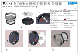
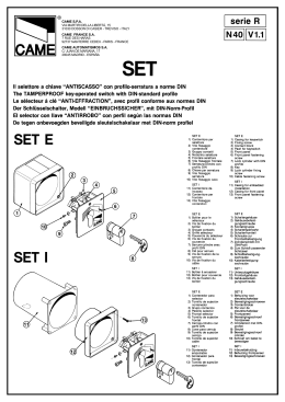
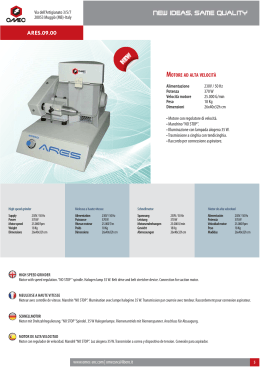
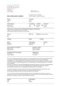
SERI EB Y
| BY SERIES | SÉRI EB
BYY | BAUREIHE BY|
Documentazion
Documentazionee
Tecnic
Tecnicaa
SERI EB
BYY
6
BY 1500
rev
rev.. 1.5
© CAME 02/99
119B6
Automazioni per cancelli scorrevol
scorrevoli i
Automation systems for sliding gates
Automatisme pour pourtails coulissant
coulissants s
Antriebe für den Schiebetore
Automatización para puertas corredera
correderas s
11
4
12 10
1 2
3
6
9
5
4
12
6
9 10
7
8
2 x 1 .5
2 x 1 - TX
32 x 1
3 x 1 .5 / 2 30 V
*
4 x 1 - RX
RG5 8
2 x 1 - TX
54 x 1 - RX
Impianto tipo
1 - Gruppo BY 1500
2 - Quadro comando
incorporato
3 - Ricevitore radio
4 - Alette finecorsa
5 - Cremagliera
6 - Costola di sicurezza
7 - Lampeggiatore di
movimento
8 - Antenna
9 - Fotocellule di
sicurezza
10 - Selettore a chiave
11- Fermo anta
12- Colonnina per
fotocellula
Standard installation
1 - BY 1500 unit
2 - Control panel
(incorporated)
3 - Radio receiver
4 - Limit switch tongues
5 - Rack
6 - Rubber safety rib
7 - Flashing light
indicating
door
movement
8 - Antenna
9 - Safety photocells
10- Key-operated selector
switch
11- Closure stop
12- Photocell column
Installation type
1 - Groupe BY 1500
2 - Armoire de
commande incorporée
3 - Récepteur radio
4 - Ailettes fin de course
5 - Crémaillère
6 - Profil de sécurité
7 - Clignotant de
mouvement
8 - Antenne
9 - Photocellules de
sécurité
10 - Sélecteur a clé
11- Butée d'arrêt
12- Colonna pour
photocellule
Standard montage
1234567-
BY 1500 Antriebsmotor
Schalttafel im Antrieb
Funkempfänger
Endschalterbügel
Zahnstange
Sicherheitsflanke
Blinkleuchte “Tor in
Bewegung”
8 - Antenne
9 - Sicherheitsphotozellen
10 - Schlüsselschalter
11- Toranschlag
12- Lichtschrankensäule
Instalación tipo
1 - Conjunto BY 1500
2 - Cuadro de mando
incorporado
3 - Radiorreceptor
4 - Aletas fin de carrera
5 - Cremallera
6 - Protector de seguridad
7 - Lámpara intermitente
de movimiento
8 - Antena
9 - Fotocélulas de
seguridad
10 - Selector de llave
11- Tope puerta
12- Columna para fotocélula
CARATTERISTICHE GENERALI // GENERAL SPECIFICATIONS // CARACTÉRISTIQUES GÉNÉRALES // ALLGEMEINES
CARACTERÍSTICAS GENERALES
Progettato e costruito inramente dalla CAME
teramente
CAME,,
te
BY 1500 risponde alle vigenti norme di sicurezza
(UNI 8612), con grado di
protezione IP54.
Designed and constructed
entirely by CAME; conforms
to (UNI 8612) safety
standards with IP 54
protection rating.
Il a été entièrement conçu
et realisé par les Ets CAME
CAME,,
conformément aux normes
de sécurité en vigueur (NFP
25362) avec degré de
protection IP54.
Vollständig von der CAME
geplant und hergestellt,
entsprechend
den
geltenden Sicherheitsbedigungen (UNI 8612) mit
Schutzgrad IP54.
Diseñado y construido
totalmente por CAME, con
arreglo a las vigentes
normas de seguridad (UNI
8612) con grado de
protección IP54.
Portata massima:
- Kg
Kg.. 1500 per uso residenziale;
- Kg
Kg.. 800 per uso intensivo.
Garantito 12 mesi salvo
manomissioni.
Maximum capability:
- Residential use: Kg. 1500
- Intensive use: Kg. 800
12 mounth guarantee;
guarantee void if unit is
tampered with.
Poids max du portail:
- Kg
Kg.. 1500 pour usage
rêsidentiel;
- Kg
Kg.. 800 pour usage
intensif;
Il est garanti 12 mois sauf
en cas d'endommagement.
Torgewicht:
- Kg. 1500 für den privaten
einsatz;
- Kg. 800 Intensivbetrieb.
12 Monate Garantie,
Bedienungs - und Montagefehler ausgeschlossen.
Peso máximo:
- Kg
Kg.. 1500 para uso
residencial;
- Kg
Kg.. 800 para uso intensivo.
Garantia de 12 meses salvo
manipulaciones.
CARATTERISTICHE TECNICHE // TECHNICAL CHARACTERISTICS // CARACTERISTIQUES TECHNIQUES
TECNISCHE DATEN // CARACTERISTICAS TECNICAS
V ER SION E
G R AD O D I
PRO TEZ ION E
PES O
ALI M ENTA Z ION E
ASS
SSO
OR BI M E NTO
POTT ENZ A
PO
IN TER M ITT ENZ A
L AV OR O
C OP PIA
RAPP ORTO D I RID U Z ION E
SP I N T A
VE LOC I TA ' M AX.
GEARMOTO R
VERSION
PROTE CTIO N
RATING
WEIGHT
POWER SU PPLY
CURRENT
POWER
DUTY CICLE
MAX TORQU E
RE DUCTION
RATIO
PUSH
MAX. SPEED
CAPACITOR
M OTOR ÉD U C TE UR
V E RSIO N
D EG RÉ D E
PROT EC TI O N
PO ID S
AL IM ENTA TIO N
AB SOR PTI O N
PU ISS
SSA
AN CE
INTE RM IT T EN C E
D E TRAV AIL
C OU PL E
R APPO
PPOR
R T D E R ED U C TIO N
P OU SS
SSÉ
ÉE
VIT ESS
SSE
E M A X.
C OND E N SATE UR
GETRIE BEM OTOR
VERSION
SCHUTZG RAD
GE WICHT
STROM_
VERSORGUN G
STROMAUFN AHME
LEISTUNG
EINSCHALT DAUER
DREHMOM ENT
UNTERSET ZUNGS_ VERHÄLTNIS
REGELBARER
MAX .
ÜBERTRAG UNGS
KONDENS ATOR
V E RSIO N
G R AD O D E
PR OTEC C IO N
PAR EJA ( M OTOR )
R EL AC IO N D E
RE DU CC
CCIIO N
EM P UJ E
V EL OC ID AD M AX.
C ON DE N SAD OR
1.5
IP 54
M OTOR ID U TT
TTO
OR E
M OTOR RED U C TOR
BY 1500
BY 1500
00TT
C OND EN SATOR E
AL IM ENTA C IO N
ABS ORB E N C IA
POTTE NC IA
PO
IN TER M ITE NC IA
TR ABAJ O
22 Kg
230V a.c .
4, 4A
500
50
0W
50 %
* 55 Nm
1/30
500 N*
10,5 m/ min.
16÷20 µ F
20 Kg
230-380 V a. c
1, 9A
500
50
0W
50 %
* 55 Nm
1/30
500 N*
10,5 m/ min.
--
PES O
* Ottenuta mediante quadro comando CAME
* Obtained with CAME control panel
* Obtenue avec une armoire de commande CAME
* Regulierbarer schub erreicht mit Hilfe der CAME Motorsteuerrung
* Empuje regulable obtenido mediante tablero de control CAME
MISURE D'INGOMBRO - OVERALL DIMENSIONS - MESURES D'ENCOMBREMENT - ABMESSUNGEN - MEDIDAS
240
22
105
Escursione massima
Maximum travel
Course maximale
Maximalausschlag
Carrera máxima
330
105
165
125
150
290
2
PRECAUZIONI // BEFORE INSTALLING ..... // AVANT D'INSTALLER L'AUTOMATISME ..... // VOR DEN INSTALLATION ÜBERPRÜFEN ...
ANTES DE INSTALAR EL AUTOMATISMO...
- Controllare che l'anta sia
rigida e compatta e che
le ruote di scorrimento
siano in buono stato e
adeguatamente ingrassate.
- La guida a terra dovrà
essere ben fissata al
suolo, completamente
in superficie in tutta la
sua lunghezza e priva di
irregolarità che possano
ostacolare il movimento
del cancello.
- I pattini-guida superiori
non devono creare attriti.
- Prevedere un fermo anta
in apertura e uno in
chiusura ed il percorso
dei cavi elettrici come da
impianto tipo.
- The gate must be sufficiently
rigid and solid.
- The wheels on which the gate
slide must be in perfect
condition and adequately
lubricated.
- The wheel guide must be
firmly attached to the ground,
completely exposed, and
without any dips or irregular
sections which might hinder
the movement of the gate.
- The upper guide must allow
for the correct amount of play
in order to guarantee smooth
and silent movement of the
gate.
- Opening and closure stops
must be installed.
- The wiring must be routed as
specified by the control and
safety requirements.
- LLe
e panneau mobile du portail
devra être suffisamment rigide et solide.
- LLes
es roues de coulissement
devront être en très bon état.
En outre, elles devront être
convenablement graissées.
- LLe
e rail de guidage devra être
bien fixé au sol. De plus, il
devra
se
présenter
entièrement en surface sans
affaissement ou irrégularité
(qui pourraient empêcher le
mouvement du portail).
- LLe
e guide supérieur devra
avoir un jeu convenable avec
le portail (pour permettre un
mouvement régulier et
silencieux).
- PPrévoir
révoir une butée d’arrêt à
l’ouverture et à la fermeture.
- Prévoir le passage des câbles
électriques selon les dispositifs
de commande et de sécurité.
- Die Leistungfähigkeit der
feststehenden und
beweglichen Teile des Tores
überprüfen.
- Das Tor sollte ausreichend
stabil sein. Die Gleitrollen
sollten in guten Zustand und
angemessen geschmiert sein.
- Die Gleitführung auf dem
Boden sollte sich in optimaler
Position befinden: gut auf
dem Boden befestigt, in seiner
Gesamtlänge vollständig
über dem Boden, ohne
Vertiefungen und/oder
Unebenheiten, die die
Torbewegung behindern
können.
- Die oberen Führungsschienen
sollten das richtige Spiel zum
Tor haben, um ein präzises
und regelmäßiges Gleiten zu
garantieren.
- Einen Anschlag für Tor Auf und
Tor Tu sollte vorhanden sein.
- Den Lauf der elektrischen
Kabel nach den Steuerungsund Sicherheitsbestimmungen
vorsehen.
- LLa
a hoja de la puerta debe
estar suficientemente rigida
y compacta.
- LLas
as ruedas de deslizamiento
deben estar perfecta y
engrasadas
adecuadamente.
- LLa
a guia de deslizamiento
debe estar bien fijada en el
suelo, sobresaliendo a lo
largo de su entera longitud,
sin huecos ni irregularidades
(que podrian obstaculizar el
movimiento de la puerta).
- LLa
a guia superior debe tener
el justo juego con la puerta
metálica (para garantizar un
movimiento regular y
silencioso).
- Disponer un tope para aper
aper-tura y el cierre.
- Disponer un conducto para
los cables eléctricos que
cumpla
con
las
disposiciones de mando y
seguridad.
FISSAGGIO BASE MOTORE // MOTOR TO BASE ANCHORAGE // FIXATION DE LA PLAQUE DU MOTEUR
BEFESTIGUNGS DER MOTORBASIS // FIJACIÓN BASE MOTOR
Anta cancello
Gate wing
Panneau mobile du portail
Gleitachse
Puerta
50 mm
Zanche
Anchor stays
Agrafes
Verankerung
Barras de hierro de fijación
105 mm
80 mm
Piazzola in cemento
Cement founadationl
Base en ciment
Plattenachse
Plataforma de cemento
Ingresso cavi
Cable entrances
Passage des cables
Kableingang
Entrada cables
Inserire le viti nella piastra
di ancoraggio bloccandole con un dado.
Predisporre,
dimensionandola in base alle
misure del motoriduttore,
una piazzola in cemento
(si consiglia di farla
sporgere dal terreno di circa
50 mm.) con annegata la
piastra di ancoraggio e
relative zanche sulla quale
sara' fissato il gruppo.
La base di fissaggio dovra'
risultare perfettamente in
bolla, pulita in tutte le sue
estremita', con il filetto delle
viti completamente in
superfice.
N.B.: Dalla stessa dovranno
emergere i tubi flessibili per
il passaggio dei cavi di
collegamento elettrico.
Install the screws in the
anchor plate and fasten them
with a nut.
Construct a cement
foundation that is large
enough to accomodate the
gear motor (it is a good idea
to protrude 50 mm. from the
ground). When pouring the
foundation, embed the gear
motor anchor plate and the
relative clamps in the cement.
The anchor bolts should be
embedded in the concrete in
the positions indicated; the
drive unit is then attached to
this bots. The anchor plate
must be perfectly level and
absolutly clean; the bolts
threads must be completly
exposed.
N.B.
N.B.: The flexible tubes for
the electrical wiring must be
embedded in the base and
protude in the correct
position.
Struttura fissa
Wall
Structure fixe
Feste Struktur
Estructura fija
Introduire les vis dans la
plaque d'ancrage en les
bloquant avec un écrou.
Préparer une base en
ciment d'une dimension
adéquate aux mesures du
motoréducteur (il est
conseillé de la faire
dépasser du terrain
d'environ 50 mm.), et noyer
dedans
la
plaque
d'ancrage et les agrafes
correspondantes afin de
permettre le fixage du
groupe.
La base de
fixation
devrà
être
parfaitement de niveau et
propre sur toute sa surface
et le filet des vis devra être
complètement en surface.
N.B
es câbles pour le
.B.. LLes
branchement électrique
devront sortir de cette base.
3
Die Schrauben in die
Ankerplatte einfügen und
mit einer Schraubenmutter
blockieren.
Eine den Abmessungen
des
Getriebemotors
entsprechende Betonfundamentplatte (Es empfiehlt
sich, diese ca. 50 mm. vom
Boden herausragen zu
lassen) zum Einbetten der
Ankerplatte und der
entsprechendenFundamentanker, die zur Befestigung
des Antriebsaggregats
dienen, vorbereiten.
Die Befestigungsunterlage
muß in seiner gesamten
Länge vollkommen eben
und sauber sein. Das
Gewinde der Schrauben
müssen
gänzlich.
hervorstehen.
Wichtig
ichtig: die Kabel für den
Elektroanschluß müssen
herausrgen.
Introducir los tornillos en
la placa de anclaje,
bloqueándolos con una
tuerca.
Preparar
reparar,, dándole las
dimensiones adecuadas
en función de
las
medidas del motor
motor-reductor
reductor,, una plataforma
de cemento (se aconseja
dejarla sobresalir del suelo
aprox. 50 mm.) con la placa de enclaje embedida y
con las correspondientes
varillas, que permitrá la
fijación del grupo.
LLa
a base de fijación debe
estar
perfectamente
nivelada, limpia en todos
sus extremos, con la rosca
de los tornillos totalmente
in superficie.
N. B
.: De ésta deben
B.:
sobresilar los tubos flexibles
para el paso de los cables
para las conexiones
eléctricas.
Acc op piam e nto pig none - cre m ag liliee ra
co n gi oco 1 ÷2 mm .
Rack-to-pinion cou pling with 1÷2 mm. clearance
Ass em bl ag
agee pi gno n-cr ém a ililèè re a v e c je u
de 1 à 2 m m.
Re go laz io ne o rizz
zzo
o nt ale e f iss ag
agg
g io
Horizontal adjustment unit and achorage
Ré gla ge ho rizo nta l e t fix ati on
Horizontale Einstellung
Re gul ació n ho
ho rizo ntal y f ijija
aci ón
1÷2 mm
mm..
POSA DEL GRUPPO // UNIT INSTALLATION // INSTALALTION DU GROUPE // AUFSTELLUNG DES AGGREGATS
COLOCACIÓN DEL GRUPO
Zwischen Zahnstange und de m Antriebsritze l
1÷2 mm. Spiel einstellen
Aco pl ami en to piñon -c re ma liliee ra
1 ÷2 m m. d e j ueg o
5÷1 0 mm.
Re go laz io ne v e rt ic ale - m e ss
ssa
a in bo lllla
a
Vertical adjustment and unit lev eling
Ré gla ge v er tic al - mi se à n iv ea u
Vertikale Einstellung
Re gul ació n v e rtica l y n iv e la ción
In gre ss
sso
o cav i
Cable entrances
P ass
ssa
a ge d es c âb
âblle s
Kabeleinfüh rungen
Entr ad
ada
a cab le s
Nella fase preliminare di
posa, i piedini dovranno
sporgere di 5-10 mm. per
permettere allineamenti,
fissaggio della cremagliera
e regolazioni successive.
L'accoppiamento
esatto
con la linea di scorrimento
del cancello è ottenibile dal
sistema di regolazione
integrale
(brevettato)
composto da:
- le asole che permettono
la regolazione orizzontale;
- i piedini filettati in
acciaio che permettono
la regolazione verticale e
la messa in bolla;
- le piastrine e i dadi di
fissaggio che rendono
solidale l'aggancio del
gruppo alla base.
During the initial phase of
installation, the feet should
protrude by 5-10 mm. in
order to allow for alignment,
anchorage of the rack and
further adjustments.
Perfect alignment with the
guide rail is made possible
by the (patented) built-in
regulation system, which
consists of:
- slots for horizontal
adjustment;
- threaded steel feet for
vertical adjustment and
levelling;
- plates and bolts for
anchorage to the base.
During the initial stages of
installations, feet must
protrude by 5 - 8 mm to
allow alignment and
Nella fase preliminare di adjustment after installation.
posa, i piedini dovranno
sporgere 5÷8 mm. per
permettere allineamenti e
regolazioni sucessive alla
posa.
Procéder maintenant à la
pose du groupe.
Dans la phase de pose
préliminaire, les broches
devront dépasser de 5 à 10
mm afin de permettre les
alignements et les réglages
nécessaires après la pose.
L’accouplement exact avec
la ligne de coulissement du
portail s’effectue par le
système de réglage hauteur
(breveté) dont le groupe est
pourvu, et qui comprend
plus précisément:
- les trous oblong permet
permet-tant le réglage horizontal;
- les broches filetées en acier
qui donnent le réglage
vertical et la mise à niveau;
- les plaques et les écrous
de fixation qui assemblent
solidement le groupe à la
plaque.
Dans la phase de pose
préliminaire, les broches
devront dépasser de 5 à 8
mm afin de permettre les
alignements et les réglages
nécessaires après la pose.
4
Nun die Montage des
Antriebsmotors vornehmen.
Die genaue Kopplung mit
der Gleitlinie des Tors wird
von dem integrierten
Einstellungssystem
(patentiert) garantiert, mit
dem
das
Aggregat
ausgestattet ist und zwar:
- die Osen für die
horizontale Einstellung,
- die Gewindefüße aus
Stahl für die vertikale
Einstellung und die
Nivellierung,
- die Befestigungsplättchen
und -muttern zur soliden
Befestigung des Aggregats
an die Bodenplatte.
Während der Vorbereitungsarbeiten der
Montage sollten die Füße
5-10 mm herausragen,
um Ausfluchtungen und
stellung zu ermöglich.
Während
der
Vorbereitungsarbeiten der
Montage sollten die Füße 5 - 8
mm herausragen, um
Ausfluchtungen
und
Einstellungen auch nach
der Fertigstellung zu
ermöglichen.
En la fase previa del
emplazamiento, los pies
deben sobresalir 5-10 mm
para
consentir
la
alineación, la fijación de la
cremallera
y
las
regulaciones sucesivas.
El acoplamiento exacto
con
la
linea
de
deslizamiento de la puerta
metálica se obtiene me
me-diante el sistema de
regulación
integral
(patentado) que consta de:
- los agujeros ovalados
que consienten la
regulación horizontal;
- las tuercas de acero que
permiten la regulación
vertical y la nivelación;
- las placas y las tuercas
de fijación que hacen
solidario el enganche del
conjunto con la base.
En la fese preliminar de la
colocación, los pies deben
sobresalir 5 a 8 mm. para
permitir la puesta en línea y
regulación después de la
colocación.
FISSAGGIO CREMAGLIERA // ATTACHING THE RACK/LIMIT // FIXATION CREMAILLÉRE // MONTAGE DE ZAHNSTANGE
FIJACIÓN DE LA CREMALLERA
Fissare la cremagliera sul Attach the rack to the gate Procéder à la fixation de la Die Zahnstange auf dem
crémaillère sur le portail de Getrieberitzel anlehnen
cancello come segue:
as described below:
la façon suivante:
(nachdem dieser in die
Eintriegelungsposition
Débloquer
le gebracht wurde), manuell
- Sbloccare il motoriduttore - Release the gearmotor motoréducteur (pag
(pag.. 6).
(pag. 6);
das Tor gleiten lassen und
(pag.6);
appoggiare
la - Position the rack on the - Placer la crémaillère sur die Zahnstange in seiner
cremagliera sul pignone del pinion of the gearmotor and le pignon motoréducteur et gesamten
Länge
motoriduttore e far scorrere slide the gate manually in faire coulisser le portail befestigen.
manualmente il cancello order to attach the rack manuellement en fixant la - Darauf achten, daß bei
crémaillère sur toute sa Metallzahnstangen im
fissando la cremagliera in along its entire length;
longueur..
Meterraster die einzelnen
tutta la sua lunghezza;
- when the rack is attached longueur
orsque la fixation de la Stücke nicht auf Stoß
- ultimata l'operazione di to the gate, adjust the feet - LLorsque
fissaggio della crema- using a screwdriver until the crémaillère est terminée montiert werden, sondern
gliera, regolare i piedini play between the pinion and régler les broches (en auf Fortlauf der Zahnung
(servendosi di un cacciavite) the rack is correct (1-2 mm.). utilisant un tournevis) de (Zahnstange am Stroß
anlegen
zur
in modo da ottenere il giusto N.B. : This position ensures façon à obtenir un jeu unten
giuoco tra pignone e that the weight of the gate convenable (1-2 mm) dans Überprüfung) .
cremagliera (1-2 mm.).
does not rest on the l’assemblage du pignon et - Die verstellbaren Füße des
de la crémaillère.
Antriebsmotors (mit einem
N.B. : Questo evitera' che gearmotor.
.B.. Ceci pour éviter que Schraubenzieher)
il peso del cancello vada a If the rack is already N.B
so
gravare sul gruppo.
attached, proceed directly le poids du portail ne einstellen, daß zwischen
Se la cremagliera é gia' to the adjustment of the repose sur le groupe.
Ritzel und Zahnstange ein
Si la crémaillère est déjà Spiel (1-2 mm) besteht.
fissata, procedere diretta- rack/pinion coupling.
mente alla regolazione When the necessary fixée, utiliser le système de Dadurch wird vermieden,
d e l l ' a c c o p p i a m e n t o adjustment have been réglage hauteur pour daß das Gewicht des Tores
pignone-cremagliera.
completed, fasten the unit assembler correctement de auf dem Aggregat lastet.
Eseguite tutte le regolazioni, in position by tightening the facon exacte le pignon et Nach
diesen
la crémaillère.
fissare il gruppo stringendo two anchor bolts.
Einstellungsarbeiten das
Exécuter tous les réglages, Aggregat durch Anziehen
i dadi di fissaggio.
fixer le groupe en serrant der beiden Muttem
les deux écrous de fixation. befestigen.
5
Colocar el motorreductor
en la posición para el
desbloqueo.
Desbloquear
el
motorreducror (pag
(pag.. 6);
- FFijar
ijar la cremallera en la
puerta metálica como se
indica a continuación.
- Apoyar la cremallera en
el piñón motorreductor y
deslizar manualmente la
puerta metálica fijando la
cremallera a lo largo de su
entera longitud.
FFinalizadas
inalizadas
las
operaciones para la
fijacion de la cremallera,
regular los pies (por medio
de un destornillador) de
modo que se obtenga el
justo juego entre el piñón
y la cremallera (1-2 mm).
N.B
.B.. Esto hace que el peso
de la puerta metálica no
cargue sobre el conjunto.
Si la cremallera ya ha sido
fijada, hay que regular el
acoplamiento piñóncremallera. Una vez
realizados los ajuste, fijar
el conjunto cerrando las
dos tuercas de fijación.
FISSAGGIO FINECORSA // ATTACHING THE SWITCH TABS // FIXATION BUTTÉES FINS DE COURSE
MONTAGE DE ENDSCHALTERBÜGEL // FIJACIÓN DE LA ALETAS DE TOPE
- Posizionare sulla
cremagliera le alette
finecorsa che determineranno, con la loro
posizione, la misura della
corsa.
- Position the limit-switch
tabs (whose positions
determine the limits of gate
travel) on the rack.
- Positionner les ailettes
de fin de course sur la
crémaillère. Leur position
déterminera la mesure de
la course.
- Die Endschalter-Rippen,
die durch ihre Stellung den
Torlauf festlegen, auf der
Zahnstange positionieren.
- Colocar en la cremallera
las aletas de final de carrera
que determinan, con su
posición, la medida de la
carrera.
Nota: evitare che il cancello
vada in battuta contro il
fermo meccanico, sia in
apertura che in chiusura.
Note: do not allow the gate
to strike the mechanical
stops in the open or closed
positions.
Remarque: il faut éviter que
le portail se porte en butée
contre l'arrêt mécanique,
aussi bien en ouverture
qu'en fermeture.
Hinweis: das Tor sollte
weder beim Öffnen noch
beim Schließen auf den
m e c h a n i s c h e n
Endanschlag auftreffen.
Nota: evitar que la puerta
choque contro el tope
mecánico, tanto en la
apertura como en el cierre.
SBLOCCO MOTORIDUTTORE // GEAR RELEASE // OPÉRATION DE DÉBLOCAGE // ANTRIEBSENTRIEGELUNG
DESBLOQUEO MOTORREDUCTOR
- Per aprire lo sportellino
inserire la chiave, spingerla
e ruotala in senso orario;
sbloccare quindi il
motoriduttore ruotando la
manopola nella direzione
indicata.
- To open the access door,
insert the key, push down
and rotate clockwise. Now,
release the gear motor by
rotating the knob in the
direction shown.
- Pour ouvrir la trappe,
introduire la clé, la pousser
et la tourner dans le sens
des aiguilles d'une montre.
Débloquer ensuite le
motoréducteur en tournant
la poignée dans la direction
indiquée.
- Zum Öffnen der klappe
den Schlüssel einfügen,
hineindrücken und im
Uhrzeigersinn drehen.
Dann den Getriebemotor
durch Drehen des Knopfs in
die angegebene Richtung
entsperren.
Blocc
cco
o
Engage
Blocag
agee
Blockierend
Bloqueo
Sblocc
cco
o
Release
Déblocag
agee
Entriegelt
Desbloqueo
6
- Para abrir la portezuela
introducir la llave,
empujarla y girarla en
sentido horario; desbloqear
el motorreductor girando
la manilla en la dirección
indicada.
ENGLISH
TECHNICAL DESCRIPTION ZBY15 MOTHERBOARD
The actuating unit is powered by
230V, single-phase, at terminals L1L2; 5A line fuses are used are used to
protect the unit. Control circuity is
powered by 24V and is protected by
1A fuses; the low voltage power
supply can also be used to power
accessories such as radio control,
photocells and others.
Gate movement cycle time is set to
100 sec. at the factory.
Safety
Photocells can be connected to
obtain:
- Re-opening during the closing cycle
(2-C);
- Partial stop, partial stopping can be
obtained by using any device
equipped with a switching relay, a
partial stop includes the following
conditions:
a) shutdown of moving gate, with
activation of an automatic closing
cycle;
b) there is no effect if partial stop is
activated when gate is completely
open or closed.
- Total stop, (1-2) shutdown of gate
movement without automatic closing;
a pushbutton or radio remote control
must be actuated to resume movement.
Other functions
- Automatic closing: The automatic
closing timer is automatically
activated at the end of the opening
cycle. The preset, adjustable
automatic closing time is
automatically interrupted by the
activation of any safety system, and is
deactivated after a STOP command
or in case of power failure;
Example
Example: photocells have been
connected to re-opening during the
closing cycle and the automatic
closure timer has been set to 30 sec.
a ) If photocells are momentarily
tripped while the gate is closing:
- gate movement reverses direction;
- the automatic closure timer is reset
at the end of the gate opening cycle.
b) If photocells path is blocked by a
stationary object while the gate is
closing:
- gate movement reverses direction;
- the automatic closure timer is reset;
- the timer is then activaded for 15
sec. and stop. Timing starts from 15
sec. when the stationary object is
removed.
c ) If photocells are momentarily
tripped at the end of the gate opening
cycle:
- the automatic closure timer operates
normally if photocells are tripped
during the first 15 sec. of timer
operation;
- the timer begins timing from 15 sec.
if photocells are tripped after the first
15 sec. of timer operation.
d) If photocells path is blocked by a
stationary object at the end of the gate
opening cycle:
- the automatic closure timer stops at
15 sec. and begins timing from 15
sec. when the object is removed.
Example
Example: photocells have been
connected to obtain partial stop and
automatic closure timer has been set
to 30 sec.
a ) If photocells are momentarily
tripped while the gate is closing:
- gate movement is stopped;
- the automatic closure timer begins
normal timing from 0 sec.
b) If photocells path is blocked by a
stationary object while the gate is
closing:
- gate movement is stopped;
- the timer is then activaded for 15
sec. and stop. Timing starts from 15
sec. when the stationary object is
removed.
c ) If photocells are momentarily
tripped at the end of the gate opening
cycle:
8
- see point c, above.
d) If photocells path is blocked by a
stationary object at the end of the gate
opening cycle:
- see point 4, above.
- "Operator present" function: Gate
operates only when the pushbutton is
held down (cut the circuit board at
the points indicated by the " symbol);
- Flashing light before gate begins to
close;
- Selection of command sequence:
-open-close-reverse;
-open only
Adjustments
-Trimmer T.P. = flashing light time: 0"
to 5";
-Trimmer TCA = Automatic closing
time: 3" to 90";
Important: disconnect the unit from
the main power lines before carrying
out any operation inside the unit.
SCHED
A BASE ZBX
SCHEDA
ZBY15
- ZBX MOTHERBOARD - CAR
TE BASE ZBX - GRUNDPLATINE ZBX - TARJET
A BASE ZBX
CARTE
ARJETA
5
3
8
1
10
7
2
6
9
4
COMPONENTI PRINCIPALI
1
2
3
4
5
Morsettiere collegamento accessori
Fusibili di linea 5A
Fusibile bassa tensione 1A
Innesto per ricevitore radio
Collegamento gruppo motore-finecorsa
MAIN COMPONENTS
1
2
3
4
5
6
7
8
9
10
GB
Collegamento ventola
Collegamento condensatore di spunto
Alimentazione 230V
Trimmer TP: regolazione prelampeggio
Trimmer TCA: regolazione tempo di chiusura automatica
COMPOSANTS PRINCIPAUX
Terminal block for connection to accessories
5A line fuses
1A accessories fuse
Socket for radio receiver
Motor unit-limit switch connection
Fan connection
Starting capacitor connection
230V power supply
Trimmer TP: flashing light time adjustment
Trimmer TCA: automatic closing time adjustment
HAUPTKOMPONENTEN
1
2
3
4
5
6
7
8
9
10
6
7
8
9
10
I
1
2
3
4
5
6
7
8
9
10
D
Plaque à bornes branchement des accessoires
Fusibles de ligne 5A
Fusible accessoires 1A
Branchement pour recepteur radio
Branchement groupe moteur-fins de course
Branchement ventilateur
Branchement condensateur de décoilage
Alimentation 230V
Trimmer TP: Réglage Temps de préclignotement
Trimmer TCA: Réglage Temps de fermeture automatique
COMPONENTES PRINCIPALES
Anschluss-Klemmenleiste Zubehör
5A-Sicherung Leitungs
1A-Sicherung Zubehörs
Steckanschluß für Funkfrequenze
Anschluß des Motor-Anschlag-Aggregats
Anschluß Ventilator
Anschluß Beschleunigungskondensator
Stromversorgung 230V
Trimmer TP: Einstellung Vorblinken
Trimmer TCA: Einstellung Zeiteinstellung Schließautomatik
1
2
3
4
5
6
7
8
9
10
12
F
Caja de bornes para las conexiónes de los accesorios
Fusible de linea 5A
Fusible accesorios 1A
Conexión para tarjeta radiorreceptor
Conexión grupo motor-fin de carrera
Conexión ventilador
Conexión condensador de arranque
Alimentación 230V
Trimmer TP: Regulación tiempo preintermitencia
Trimmer TCA: Regulación cierre automático
E
ZBY15
COLLEGAMENT
O FINECORSA
COLLEGAMENTO
- LIMIT SWITCH CONNECTIONS - BRANCHEMENT FIN DE COURSE
ENDAUSSCHALTER-ANSCHLUSS
FA
ITALIANO
TM
U W V
SX
NC
NC
Gruppo motore-finecorsa già collegati per montaggio a sinistra vista
interna. Per eventuale montaggio a destra:
- invertire FA-FC dei finecorsa sulla morsettiera;
- invertire le fasi U-V del motore sulla morsettiera.
FC
- CONEXION FINAL DE CARRERA
ENGLISH
COM
The motor and limit switch unit are wired at the factory for mounting on
the left-hand side of the gate (as seen from the inside).
If right-hand installation is desired:
- invert limit switch connections FA-FC on the terminal block;
- invert motor phase connections U-V on the terminal block.
FRANÇAIS
Groupe moteur-fins de course déjà branchés pour le montage à gauche
- vue de l'intérieur. Pour un éventuel montage à droite:
- inverser FA-FC des fins de course sur la plaque à bornes;
- inverser les phases U-V du moteur sur la plaque à bornes.
FA
FC
Motore monofase 230V
230V single-phase motor
Moteur monophasé 230V
Einphasiger Motor 230V
Motor monofásico de 230V
TM
U W V
DX
NC
COM
Das Motor-Anschlag-Aggregat schon für die Montage auf der linken
Seite angeschlossen, interne Ansicht.
Für eine eventuelle Montage auf der rechten Seite:
- die Öffnungs- und Schließungsphasen auf dem Klemmbrett invertieren;
- die U-V Phasen des Motors auf dem Klemmen tauschen.
Gruppo finecorsa
Limit switch unit
Groupe fins de course
Anschlag-Gruppe
Grupo fin de carrera
NC
DEUTSCH
M
M
ESPANIOL
Grupo motor-fin de carrera ya conectados para el montaje a la izquierda
vista interior. Para el eventual montaje a la derecha:
- invertir FA-FC de los fines de carrera en el cuadro de bornes;
- invertir las fases U-V del motor en el cuadro de bornes.
Gruppo finecorsa
Limit switch unit
Groupe fins de course
Anschlag-Gruppe
Grupo fin de carrera
Motore monofase 230V
230V single-phase motor
Moteur monophasé 230V
Einphasiger Motor 230V
Motor monofásico de 230V
SCHEMA COLLEGAMENT
O MO
TORE TRIF
ASE - WIRING DIAGRAM TRI-PHASE MOTOR - SCHÉMA DE BRANCHEMENT MO
TEUR TRIPHASÉ
COLLEGAMENTO
MOT
TRIFASE
MOTEUR
TOR TRIFÁSICO
MOT
ANSCHLUßSCHEMA DREIPHASESIGER MOTOR - ESQUEMA DE CONEXIÓN MO
Collegamento per alimentazione 380V
Wiring arrangement for connection to 380V
Branchement pour alimentation 380V
Stromanschluß 380V
Conexión para alimentación de 380V
W2
U2
V2
U1
V1
W1
Collegamento gruppo finecorsa BY1500 trifase
Wiring diagram BY1500 triple phase limit switch unit
Branchement groupe fins de course BY1500 triphasée
Anschluß der Anschlagsgruppe BY1500 dreiphasig
Conexión grupo fin de carrera BY1500 trifásico
0
Fa
Fc
Collegamento per alimentazione 220V
Wiring arrangement for connection to 220V
Branchement pour alimentation 220V
Stromanschluß 220V
Conexión para alimentación de 220V
W2
U2
V2
U1
V1
W1
N.B.: É consigliabile installare il quadro comando CAME «ZT4»
Note: We recommend installation of the CAME «ZT4»
N.B.: Il est conseillé d'installer l'armoire de commande CAME «ZT4»
N.B.: Die installierung der Steuerung CAME «ZT4» ist empfehlenswert
Nota: Es aconsejable instalar el cuadro de mando CAME «ZT4»
13
COLLEGAMENTI ELETTRICI
ZBY15
- ELECTRICAL CONNECTIONS - BRANCHEMENTS ÉLECTRIQUES - ELEKRISCHE ANSCHLÜSSE - CONEXIONES ELÉCTRICAS
L1 L2 W E
T1 0 1 2 3 4 C T2 7 A P 8 B1 B2
C OLL.
VENT.
W
E
Uscita 230V (a.c.) in movimento (es.lampeggiatore - 25W)
230V (a.c.) output in motion (e.g. flashing light - 25W)
Sortie 230V (c.a.) en mouvement (ex. branchement clignotant - 25W)
Ausgang 230V (Wechselstrom) in Bewegung (z.B. Blinker-Anschluß - 25W)
Salida de 230V (a.c.) en movimento (p.ej. conexión lámpara intermitente - 25W)
0
1
Alimentazione accessori 24V (a.c.) max. 20W
24V (a.c.) Powering accessories (max 20W)
Alimentation accessoires 24V (a.c.) max.20W
Zubehörspeisung 24V (Wechselstrom) max. 20W
Alimentación accesorios 24V (a.c.) max. 20W
1
2
Pulsante stop (N.C.)
Pushbutton stop (N.C.)
Bouton-poussoir arrêt (N.F.)
Stop-Taste (N.C.)
Pulsador de stop (N.C.)
2
3
Pulsante apre (N.O.)
Pushbutton open (N.O.)
Bouton-possoir ouverture (N.O.)
Taste Öffnen (N.O.)
Pulsador de apertura (N.O.)
2
4
Pulsante chiude (N.O.)
Close button (N.O.)
Poussoir de fermeture (N.O.)
Taste Schließen (Arbeitskontakt)
Pulsador de cierre (N.O.)
1
FA
Lampada spia (24V-3W) cancello chiuso
24V-3W gate-closed signal lamp
Lampe-témoin (24V-3W) portail fermé
Signallampe (24V-3W), geschlossenes Tor
Lampara indicadora (24V-3W) puerta cerrada
1
FC
Lampada spia (24V-3W) cancello aperto
24V-3W gate-opened signal lamp
Lampe-témoin (24V-3W) portail ouverture
Signallampe (24V-3W), offenes Tor
Lampara indicadora (24V-3W) puerta abierta
4
3
2
Selettore a chiave
Key-operated selector switch
Sélecteur à clé
Schlüsselschalter
Selector de llave
14
Per installare più pulsantiere collegare: i pulsanti stop in serie, i pulsanti apre-chiude,
lampada spia in parallelo
To install supplementary pushbutton arrays: connect stop buttons in series, connect
open-close buttons and warning lights in parallel
Pour installer plusieurs panneaux de boutons-poussoirs, il faut connecter: les boutonspoussoirs stop en série, les boutons-poussoirs ouverture-fermeture, lampe-témoin en
paralléle
Zum Installieren mehrerer Schalterreihen, folgendermaßen verbinden: die Stop-Tasten
hintereinander, die Taste Öffnen-Schließen, Signallampe parallel
Para instalar más botoneras conectar: los pulsadores de stop en serie, los pulsadores
de apertura-cierre-lámpara indicadora en paralelo
L1
L2
Alimentazione 230V (a.c.)
230V (a.c.) power input
Alimentation 230V (c.a.)
Stromversorgung 230V (Wechselstrom)
Alimentación 230V (a.c.)
COLLEGAMENTI ELETTRICI
ZBY15
- ELECTRICAL CONNECTIONS - BRANCHEMENTS ÉLECTRIQUES - ELEKRISCHE ANSCHLÜSSE - CONEXIONES ELÉCTRICAS
L1 L2 W E
T1 0 1 2 3 4 C T2 7 A P 8 B1 B2
C OLL.
VENT.
Contatto radio e/o pulsante apre-chiude ed inversione
Contact radio and/or pushbutton open-close and movement reversal
Contact radio et/ou bouton-poussoir ouverture-fermeture et inversion
Funkkontakt und/oder Taste Öffnen-Schließen und Umkehrung
Contacto radio y/o pulsador de apertura-cierre e inversión
2
7
3
7
A
Con radiocomando: -apre-chiude-inversione, collegare i morsetti A-7 tra loro
-solo apre, collegare i morsetti A-3 tra loro
Using radio control: -open-close-reversal, connect terminal A to terminal 7
-open only, connect terminal A to terminal 3
Avec radiocommande:
-ouverture-fermeture-inversion, connecter les bornes A-7 entre elles
radiocommande:-ouverture-fermeture-inversion,
-seulement ouverture, connecter les bornes A-3 entre elles
Mit Funksteuerung:
-Öffnen-Schließen-Umkehrung, die Klemmen A-7 miteinander verbinden
-nur Öffnen, die Klemmen A-3 miteinander verbinden
Con radiocomando: -apertura-cierre-inversión, conectar entre si los bornes A-7
-sola apertura, conectar entre si los bornes A-3
Contatto (N.C.) di «riapertura durante la chiusura»
Nel caso questa funzione non fosse prevista, collegare i morsetti 2-C tra loro
Contact (N.C.) for «re-aperture during closure»
If this function is not used, connect terminal 2 to terminal C
Contact (N.F.) de «réouverture pendant la fermeture»
Si cette fonction n'est pas prévue, connecter les bornes 2-C entre elles
Kontakt (Ruhekontakt) «Wiederöffnen beim Schliessen»
Falls diese Funktion nicht vorgesehen ist, die Klemmen 2-C mitelnander verbinden
Contacto (N.C.) para la «apertura en la fase de cierre»
En caso de que esta función no esté prevista, conectar entre si los bornes 2-C
2
C
3
8
P
Contatto (N.C.) stop parziale
Nel caso questa funzione non fosse prevista, collegare i morsetti P-8 tra loro
Partial stop contact (N.C.)
If this function is not used, connect terminal P to terminal 8
Contact (N.F.) d'arrêt partial
Si cette fonction n'est pas prévue, connecter les bornes P-8 entre elles
Teil-Stop (Ruhekontakt) Kontakt
Falls diese Funktion nicht vorgesehen ist, die Klemmen P-8 mitelnander verbinder
Contacto (N.C.) de stop parcial
Collegamento antenna
Antenna connection
Connexion antenne
Antennenanschluß
Conexión antena
B1
B2
Uscita contatto (N.O.) Portata contatto: 5A a 24V(d.c.)
Contact output (N.O.) Resistive load: 5A 24V (d.c.)
Sortie contact (N.O.) Portée contact: 5A a 24V(c.c.)
Ausgang Arbeitskontakt Stromfestigkeit: 5A bei 24V (Gleichstrom)
Salida contacto (N.O.) Carga resistiva: 5A a 24V (d.c.)
T1
T2
Interruttore per inserimento chiusura automatica
Automatic closure activationswitch
Interrupteur pour enclenchement fermeture automatique
Schalter zur Einfügung der automatischen Schließung
Interruptor para conexión cierre automático
15
LIMITATORE DI COPPIA MOTORE / MOTOR TORQUE LIMITER /LIMITEUR DE COUPLE MOTEUR
DREHMOMENTBEGRENZER DES MOTORS /LIMITADOR DE PAR MOTOR
Per variare la coppia motore, spostare il faston indicato su una delle 4
posizioni; 1 min - 4 max.
To vary the motor torque, move the indicated faston to one of the four
positions: 1=min, 4=max
L2 T 1
Pour varier le couple du moteur, déplacer le connecteur indiqué sur l'une
des 4 positions; 1 min. - 4 max.
2 3 4 L1T
012 24
Zur Änderung des Motor-Drehmoments den angegebenen Faston auf eine
der 4 Stellungen positionieren: 1 min. - 4 max.
Para variar el par motor, desplazar el faston indicado hasta una de las 4
posiciones; 1 mín. - 4 máx.
COLLEGAMENTO ABBINATO / INSTALL TWO MOTORS IN JOINT / APPLICATION DE DEUX MOTEURS ASSEMBLÉS
ANBRINGUNG VON BEIDEN GEKOPPELTEN MOTOREN /APLICACION DE DOS MOTORES ACOPLADOS
1) Coordinare i sensi di marcia dei due motori (destra e sinistra) .
2) Eseguire sulla morsettiera motore A i collegamenti come indicato pag
pag.. 14-15.
3) Collegare il motore B come indicato nello schema qui raffigurato ; (* *) contatto di riapertura in fase di chiusura, (*) pulsante di stop totale
collegati come indicati nello schema qui raffigurato.
1) Coordinate left-right travel of the two motors.
2) Wire the motor A terminal block as shown in the diagram on page 14-15.
3) Connect motor B as shown in the diagram above ; (* *) contact for re-opening during closure and (*) total stop bush button are connected
as shown above.
1) Coordonner les sensde la marche deus deux moteurs (droite -gauche).
2) Effectuer les connexions sur la plaque à bornes du moteur A de la façon indiquée dans le schéma de la page 14-15.
3) Bracher le moteur B de la façon indiquée dans le schéma ci dessus représenté ; (* *) contact de réouverture en phase de fermeture et (*)
bouton-poussoir d'arrêt total connectés de la façon indiquée dans le schema cidessus.
ci-dessus.
1) Die Gangrichtung der beiden Motor koordinieren (rechts-links).
2) Die Anschlüsse auf dem Klemmbrett von motor A wie auf dem Schema auf Seite 14-15 ausfüren.
3) Den Motor B wie auf dem hier aufgefürten Schema anschließen:(*) die drucktaste Totalstop und (**) den Kontakt der Wiederöffnung
während der Schließung wie auf dem hier gezeigten Schema anschließen.
1) Coordinar los sentidos de marcha de los dos motores (derecha-izquierda).
2) Efectuar en el cuadro de bornes motor A las conexiones como muestra el esquema de la pàg 14-15.
3) Conectar el motor B como muestra el esquema de esta pàgina ; (**) contacto de apertura durante la fase de cierre y (*) pulsador de stop
total conectados como muestra el esquema de esta pàgina.
Morsettiera motore "A": motore pilota
Motor "A" terminal block: pilot motor
Plaque à bornes du moteur "A": moteur pilote
Klemmbrett Motor "A": Steuerugsmotor
Cuadro de bornes motor "A": motor piloto
Morsettiera motore "B"
Motor "B" terminal block
Plaque à bornes du moteur "B"
Klemmbrett Motor "B"
Cuadro de bornes motor "B"
T1 0 1 2 3 4 C T2 7 A P 8 B1 B2
Pulsante stop (N.C.)
Pushbutton stop (N.C.)
Bouton-poussoir arrêt (N.C.)
Stop-Taste (N.C.)
Pulsador de stop (N.C.)
Tutti i dati riportati nel presente libretto sono
indicativi. La CAME s.p.a. si riserva di apportare eventuali modifiche inerenti all'evoluzione
tecnologica dei prodotti.
*
T1 0 1 2 3 4 C T2 7 A P 8 B1 B2
Contatto (N.C.) di «riapertura durante la chiusura»
Contact (N.C.) for «re-aperture during closure»
Contact de «réouverture pendant la fermeture» (N.C.)
Viederöffnungskontakt während des Schließens (N.C.)
Contacto para apertura durante la fase de cierre (N.C.)
**
All data mentioned in the present booklet are for
information only. CAME SPA reserves the right to
introduce changes relating to technological
improvements of the products.
CAME S.P.A.
VIA MARTIRI DELLA LIBERTÀ, 15
31030 DOSSON DI CASIER
TREVISO
CAME SUD S.R.L.
VIA FERRANTE I MPARATO, 198
CM2 LOTTO A/7
80146 NAPOLI
Toutes les données mentionnées dans le livret
sont indicatives. CAME se réserve le droit
d'apporter des modifications éventuelles par
rapport à l'évolution téchnologique des produits.
ITALIA
CAME AUTOMATISMOS S.A.
Alle in der vorliegenden Beschreibung
angegebenen Daten dienen nur der information.
CAME S.P.A. behält sich technische Andernungen
vor.
ESPAÑA
C/JUAN DE MARIANA, 17
28045 MADRID
ITALIA CAME GMBH
Todos los datos de este libreto son indicativos.
CAME s.p.a. se reserva el derecho de aportar
las modificaciones producidas por la evolución tecnológica de los productos.
DEUTSCHLAND
internet
www.came.it
e-mail
[email protected]
BERGSTRASSE, 17/1
70825 KORNTAL
STUTTGART
ASSISTENZA TECNICA
CAME FRANCE S.A.
7 RUE DES HARAS
92737 NANTERRE CEDEX
PARIS
FRANCE CAME GMBH
AKAZIENSTRASSE, 9
16356 SEEFELD
BERLIN
DEUTSCHLAND
NUMERO VERDE
800-848095
N° 12 100 8953
Scarica