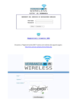
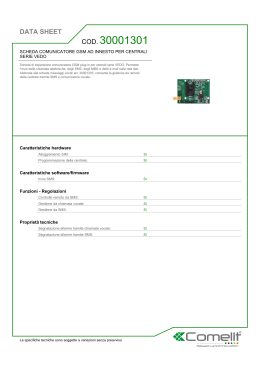
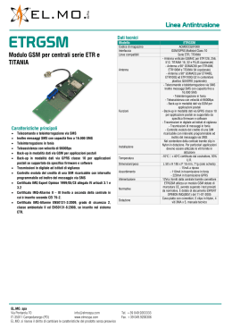
BGSM-I
I
G
E
F
S
INTERFACCIA GSM
GSM INTERFACE
INTERFAZ GSM
INTERFACE GSM
GSM UPPRINGARE
®
MADE
IN
ITA LY
2
1
15
54
17
3 6 7 4
18
S IM
8
6
9
1
5
10
9
11
19
12
LE
LI
O1 O2 O3 O4
AS
L 1 L 2 L 3 L 4 +12V-
14
13
16
4
®
Fig. 1 - Parti - Parts - Componentes - Composants - Komponenter och detaljer
Componentes
Composants
Komponenter
och detaljer
Coperchio metallico
Metal Casing
Cubierta metálica
Couvercle métallique
Metallkapsling
Antenna GSM
GSM Antenna
Antena GSM
Antenne GSM
GSM-antenn
Ecrous de fixation
de l'Antenne GSM
Trous de fixation
(Ø 3 mm)
Connecteur
de l'Antenne GSM
Parti
1
2
Bullone di fissaggio
dell'Antenna GSM
Fori fissaggio fondo
(Ø 3 mm)
Connettore
Antenna GSM
Anchor Screw holes
(Ø 3 mm)
Connector
for GSM Antenna
Pernod de fijación
de la Antena GSM
Agujeros de fijación
(Ø 3 mm)
Cable
Antena GSM
6
SIM-CARD
SIM CARD
Tarjeta SIM
Carte SIM
SIM-kort
7
LEDs di segnalazioni
LEDs
LEDs
LEDs
Lysdioder
8
Trimmer Riservato
Reserved Trimmer
Trimmer Reservado
Trimmer Reservé
Potentiometer
för produktion
9
Ponticello Riservato
Reserved Jumper
Puente Reservado
Pontet Reservé
Bygel för produktion
10
Connettore RS-232
RS-232 Connector
Conector RS-232
Connecteur RS-232
Anslutning för RS-232
3
4
5
2
Parts
N.
GSM Antenna nuts
Fäste för GSM-antenn
Hål för monteringsskruvar
Anslutning för antennkabel
BGSM-I
Co llegam ento fo ndam entale
This Co nn ection is neces sary
Co nexión básica
Co nnexio n nécessa ire
Dessa ink op plin gar m åste u tföras
<9
1 2 3 4 5
?! ?" ?# ?$
6 7 8 9 10 11
12 13
<! <" <# <$
14 15 16 17 18 19 20
13.8 V Alla linea AS
To Tam per L ine
A la Linea Antisabotaje
Sabotage
Till sabo tagesling a
700 m A
C entrale A ntifurto / Centrale Antincendio
Fire Panel / Security Panel
C entral de Incendios / C entral A ntirrobo
C entrale Incendie / C Entrale d’Alarm e
C entralapparat
Fig. 2 - Esempio di Collegamento - Wiring Diagram - Ejemplo de conexión - Cablage - Inkoppling
N.
Parti
Parts
11
Microswitch antiapertura Frontplate Tamper Switch
12
Morsettiere collegamenti
13
14
15
16
17
Cavetti Batteria
Terminal Board
Componentes
Composants
Komponenter och
detaljer
Microinterruptor
Antisabotaje
Antisabotage
Sabotagekontakt för
skydd av frontplatta
Bornera de conexiones
Bornier
Kopplingsplint
Battery Connector
Cables de Batería
Cosses de Batterie
Batterikablar med
kontakter
Cable entry
Agujero pasacables
Passage pour câbles
Införingshål för kablar
Apertura
per passaggio cavi
Cavetto
collegamento Terra
Batteria 12V-1,2Ah
(non fornita)
12V-1.2Ah Battery
(not supplied)
Modulo GSM
GSM Module
Módulo GSM
Module GSM
SIM holder
PortaSIM
Logement carte SIM
18
Porta SIM-CARD
19
Lampadina 24 V - 3 Watt
®
Hearth Cable
Cable
Câble
de Tierra
de Terre
Acumulador de 12V-1,2Ah Batterie 12Volts - 1,2Ah
(no suministrado)
(non fournie)
24 V - 3 Watt light bulb Bombilla de 24 V - 3 Watt Ampoule 24 V - 3 Watt
Jordanslutning
12 V, 1,2 Ah batteri
(ingår inte)
GSM-modul
Hållare för SIM-kort
24 V, 3 W glödlampa
3
INDICE
INTRODUZIONE ..................................................................................... 5
Caratteristiche Generali .................................................................................... 5
Caratteristiche Tecniche ................................................................................... 5
Descrizione Generale ...................................................................................... 5
IDENTIFICAZIONE DELLE PARTI ......................................................
INSTALLAZIONE ....................................................................................
COLLEGAMENTI ....................................................................................
SPIE DI CONTROLLO ...........................................................................
MODALITA’ DI FUNZIONAMENTO ....................................................
6
6
6
7
7
Funzionamento come Interfaccia GSM ............................................................. 7
Funzionamento come Avvisatore SMS ............................................................. 7
Funzionamento come Avvisatore Contact ID .................................................... 8
Gestione delle Priorità ..................................................................................... 8
Priorità di Funzionamento all’Interfaccia ........................................................................ 8
Priorità di Funzionamento all’Avvisatore (SMS o Contact ID) ....................................... 8
Priorità degli Eventi dell’Avvisatore ................................................................................. 8
ATTIVAZIONE DELLE USCITE ............................................................. 8
Attivazione e disattivazione delle Uscite in automatico .................................... 8
Attivazione e Disattivazione delle Uscite da remoto ......................................... 9
Uscite Bistabili .................................................................................................................. 9
Uscite Monostabili ........................................................................................................... 9
INTRODUZIONE ALLA PROGRAMMAZIONE ................................. 9
PROGRAMMAZIONE DA PC ............................................................. 10
Leggere la Programmazione dal BGSM-I ................................................................... 10
Inviare la Programmazione sul BGSM-I ....................................................................... 10
Operazioni preliminari .................................................................................................. 10
Pagina Telefono ............................................................................................. 10
Sezione Numeri Telefonici ........................................................................................... 10
Prefisso ......................................................................................................................... 11
Cifre da rimuovere ....................................................................................................... 11
Pagina Avvisatore SMS .................................................................................. 11
Sezione Principale .......................................................................................................
Priorità ..........................................................................................................................
Controllo credito residuo .............................................................................................
SMS Periodico ..............................................................................................................
11
11
12
12
Pagina Uscite ................................................................................................ 12
Sezione Impostazione Uscite ...................................................................................... 12
Codice Utente ............................................................................................................. 12
Pagina Comunicatore Contact ID .................................................................... 12
Numeri da chiamare .................................................................................................... 12
Tabella Eventi ............................................................................................................... 13
Segnalazione periodica ............................................................................................... 13
Pagina Chiamate ........................................................................................... 13
Pulsante Carica ...........................................................................................................
Sezione Chiamate Ricevute .......................................................................................
Sezione Chiamate Perse ............................................................................................
Sezione Chiamate Effettuate .....................................................................................
13
13
13
13
Pagina Stato .................................................................................................. 13
Sezione Stato ..............................................................................................................
Sezione Ingressi ..........................................................................................................
Sezione Uscite .............................................................................................................
Sezione Eventi .............................................................................................................
Prossimo Invio SMS Periodico ......................................................................................
Prossimo Invio Segnalazione Periodica ......................................................................
Cancella coda telefonica ............................................................................................
13
13
14
14
14
14
14
Programmazione Remota ............................................................................... 14
PROGRAMMAZIONE MANUALE ..................................................... 15
Introduzione ................................................................................................... 15
Programmazione dei Numeri Telefonici nella Rubrica ...................................... 15
Configurazione del BGSM-I ............................................................................ 15
1° SMS - Configurazione delle Uscite ........................................................................
2° SMS - Configurazione l’Avvisatore SMS .................................................................
3° SMS - Altre Configurazioni ......................................................................................
4° SMS - Configurazione l’Avvisatore Digitale ............................................................
15
16
17
17
SMS dell’Avvisatore ...................................................................................... 18
Programmazione da remoto ............................................................................ 18
INFORMAZIONI PER L’UTENTE ...................................................... 19
Modifica del Codice Utente da remoto ............................................................. 19
Per effettuare una telefonata ........................................................................... 19
Altre informazioni ........................................................................................... 19
4
BGSM-I z Interfaccia GSM
INTRODUZIONE
I
Caratteristiche Generali
Fornisce una linea PSTN simulata
Rilevamento assenza linea PSTN e commutazione automatica su Rete GSM
Gestione e segnalazione delle telefonate in entrata ed in uscita
Indicatore di intensità del campo GSM
4 Uscite Open-Collector programmabili
Alloggiamento per una batteria tampone da 12V - 1,2 Ah (non inclusa)
Protezione contro i sabotaggi
Protezione da sovratensioni sulla linea telefonica
Dual-Band
4 Linee di Ingresso
Avvisatore SMS
Avvisatore Contact ID
13 Messaggi SMS (2 per ogni Linea di Ingresso più 5 per Segnalazioni di Stato)
8 numeri telefonici (max. 20 cifre) programmabili per l’Avvisatore SMS
4 numeri telefonici programmabili per l’Avvisatore Contact ID
Fino a 95 numeri telefonici (max. 20 cifre) programmabili per l’attivazione da remoto delle Uscite OC
Attivazione delle uscite da remoto mediante riconoscimento del chiamante e/o l’invio di SMS
Controllo credito residuo delle SIM-CARD prepagate
Caratteristiche Tecniche
Per un corretto funzionamento, l’Interfaccia richiede una tensione di alimentazione di 13,8 V_ , 700 mA massimo prelevabile
direttamente dalla Centrale oppure dall’alimentatore ADP1512 (accessorio da richiedere a parte).
Tensione di alimentazione:
13,8 V_
Assorbimento massimo:
700 mA
Temperatura di funzionamento: da +5° a +40° C
Dimensioni (mm):
138 x 224 x 55
Peso (senza batteria):
900 g
Descrizione Generale
Il BGSM-I è un dispositivo che permette di accedere alla Rete GSM e può funzionare in due diverse modalità: AVVISATORE
ed INTERFACCIA come descritto nei successivi capitoli. Nel campo dei sistemi di sicurezza, essa risulta indispensabile
in tutti quei casi in cui non si dispone della Linea Telefonica convenzionale (PSTN).
Inoltre il BGSM-I è in grado di gestire telefonate verso le Stazioni di Televigilanza: in questo caso le prestazioni offerte
dipendono fortemente dal Gestore della Rete GSM e dal livello di copertura della zona.
Si è comunque rilevato che il protocollo CONTACT ID, i protocolli 10 bps, 20 bps e, in condizioni ottimali di campo, anche
i protocolli SIA e CESA, transitano con buona affidabilità sulla rete GSM.
In ogni caso è da ritenere a rischio di insuccesso una comunicazione che avvenga nella condizione del Led di campo
lampeggiante. È pertanto sempre necessario effettuare delle prove di comunicazione nelle reali condizioni di installazione al
fine di valutare l’affidabilità della connessione. Inoltre il BGSM-I dispone di 4 Linee di Ingresso per attivare l’Avvisatore SMS
e/o l’Avvisatore Contact ID che possono essere utilizzati anche per inviare segnalazioni di stato.
Con il BGSM-I è possibile attivare da remoto una o più delle 4 uscite disponibili, altrimenti utilizzate per segnalazioni di stato.
A causa delle caratteristiche della rete GSM, il BGSM-I è da utilizzare esclusivamente nei casi sopraddetti, quindi non come
modem per la trasmissione di fax e dati o per operazioni di Teleassistenza.
Il BGSM-I viene fornito in contenitore metallico protetto contro i tentativi di sabotaggio e dotato di chiare segnalazioni sul suo
funzionamento.
®
5
IDENTIFICAZIONE DELLE PARTI
In Fig. 1 è riportata la lista numerata delle parti più importanti del BGSM-I. Nei successivi paragrafi, i numeri riportati tra
parentesi quadre [ ] fanno riferimento a queste parti.
INSTALLAZIONE
, Prima dell’installazione, fare molta attenzione alla copertura della zona da parte del Gestore di Rete GSM.
Per installare il BGSM-I, scegliere un luogo sicuro, non locali aventi mura spesse e lontano da apperecchi radio-trasmittenti.
1. Rimuovere il coperchio [1] svitando le 2 viti che lo tengono fissato al fondo.
2. Dopo aver scelto il punto per il fissaggio, posare tutti i cavi necessari,
quindi far passare questi ultimi attraverso le aperture [14] posta sul fondo
del contenitore (vedi figura a lato).
3. Facendo attenzione a non danneggiare fili o tubazioni sottotraccia, praticare i 4 fori sulla parete, inserire i 4 tasselli (non forniti) e fissare il fondo
utilizzando i fori [4] presenti sullo stesso.
4. Montare l’antenna [2] controllando che sia ben avvitata al fondo metallico
mediante il bullone [3].
5. Inserire il connettore [5] sul Modulo GSM [17].
6. Inserire la SIM-CARD [6] (assicurandosi che sulla stessa sia
disabilitato il Controllo PIN): la SIM-CARD va inserita con i contatti
rivolti verso quelli del porta-SIM e la tacca di riferimento come indicato in
Fig. 1 (fare riferimento al disegno della freccia presente sulla scheda per
il verso di inserimento). La disabilitazione del controllo PIN può essere
effettuata anche dal Software di gestione.
7. Eseguire i collegamenti richiesti sulle morsettiere [12].
8. Riposizionare il coperchio [1] e fissarlo con 4 viti (in dotazione) avendo cura di interporre tra la vite ed il coperchio stesso
le apposite rondelle in dotazione.
COLLEGAMENTI
In Fig. 2 è riportato un esempio di collegamento. Di seguito viene data una descrizione dei vari morsetti.
- (1) Terra. Questo morsetto deve essere collegato alla Terra dell'impianto elettrico per proteggere il BGSM-I dalle
sovratensioni sulla linea telefonica e per soddisfare i requisiti di sicurezza della rete di telecomunicazione.
LE (2-3) Linea Telefonica Esterna. Su questi morsetti può essere collegata la linea telefonica analogica (PSTN).
L I (4-5) Linea Telefonica Interna. Su questi morsetti vanno collegati quelli del dispositivo telefonico (avvisatore telefonico,
L.E. sui nostri articoli) che solitamente vengono collegati alla Linea Telefonica Esterna.
M (6-14) Massa. Negativi di alimentazione
0x (7-8-9-10) Uscite Open-Collector Programmabili per essere attivate da remoto oppure attraverso il verificarsi di un
certo evento (vedi paragrafo ‘Attivazione delle Uscite’ più avanti in questo manuale). La corrente massima prelevabile
da ciascuna Uscita OC non può superare i 70 mA
+OC (11) Comune per Open Collector. Morsetto per l’alimentazione comune (12 Vcc-450mA) di tutte le Uscite OC (O1, O2,
O3, O4).
AS (12-13) Linea Antisabotaggio. Questi morsetti, che risultano internamente collegati in serie con i contatti del microswitch
antisabotaggio [11] risultano in cortocircuito quando il coperchio del BGSM-I è perfettamente chiuso e si aprono non
appena quest’ultimo viene rimosso.
Lx (15-16-17-18) Linee di Ingresso Programmabili. Morsetti utili per l'attivazione delle funzioni dell’Avvisatore.
12V (19-20) Alimentazione del BGSM-I. Collegare questi morsetti ad una alimentazione di 13,8 V_ , 700 mA minimo
generalmente proveniente da una Centrale oppure dall’alimentatore ADP1512 (opzionale). In caso di collegamento ad
una centrale è necessario assicurarsi che tale alimentazione sia protetta e limitata in corrente a 700 mA.
Terminati i collegamenti, collegare i due cavetti Rosso e Nero [13] ad una batteria da 12V-1,2Ah.
, I collegamenti con la batteria tampone, con la Terra e con l’alimentazione da 13,8 V sono sempre necessari
(Vedi Fig. 2).
, In caso di sostituzione, smaltire le batterie usate in accordo alle normative vigenti.
6
BGSM-I z Interfaccia GSM
SPIE DI CONTROLLO
I
Il dispositivo possiede sul pannello frontale 4 spie di tipo LED dei quali si riporta una breve descrizione.
, Durante l’inizializzazione e durante la fase di programmazione, tutti i led lampeggiano simultaneamente.
VERDE. Se spento indica l’assoluta mancanza di segnale GSM. In questo caso si accende contemporaneamente
anche il LED ROSSO. Se lampeggiante, indica un basso livello di segnale GSM: in tal caso funziona correttamente solo
la modalità AVVISATORE SMS. Se acceso fisso, il livello di segnale GSM è sufficente per effettuare anche le chiamate
vocali.
Y VERDE. Se acceso indica una buona intensità di campo GSM. Questo LED si accende solo ed esclusivamente quando
anche l’altro LED VERDE è acceso fisso.
t GIALLO. Se acceso fisso indica che l’Interfaccia ha commutato sulla Rete GSM a causa di anomalie della Linea
Telefonica esterna. Se lampeggiante, indica una chiamata in corso in entrata o in uscita (indipendente o meno dalla
presenza della Linea Esterna).
G ROSSO. Normalmente spento, se lampeggiante, indica presenza di problemi di alimentazione. Se è acceso fisso,
indica un guasto del Modulo GSM [17] oppure la mancanza delle Rete GSM oppure, se è abilitata, la programmazione
da remoto. Se questo LED è acceso fisso e contemporaneamente i due LED VERDI segnalano presenza di campo GSM,
significa che è possibile effettuare solo ed esclusivamente le chiamate di emergenza.
y
MODALITA’ DI FUNZIONAMENTO
Funzionamento come Interfaccia GSM
L’interfaccia permette di connettere la linea telefonica esterna, essendo completamente passante su tale linea telefonica, fino
a che quest’ultima non presenti un’anomalia. Quando questo accade il BGSM-I commuta la linea telefonica proveniente dal
dispositivo telefonico sulla rete GSM. In queste condizioni il BGSM-I genera una linea PSTN simulata (tono continuo),
fornendo la tensione di linea e di squillo per le chiamate in arrivo e decodificando automaticamente la selezione delle chiamate
in partenza in multifrequenza (la selezione decadica non viene gestita).
La commutazione tra la linea PSTN e la linea simulata avviene quando la tensione sulla linea PSTN, presente sui morsetti
(LE-Linea Telefonica Esterna), scende sotto i 3 V per un tempo compreso tra 10 e 45 secondi (tempo che dipende dal
dispositivo connesso ai morsetti LI-Linea Telefonica Interna). Una volta avvenuta questa commutazione il BGSM-I farà
si che per i successivi 15 minuti il dispositivo ad esso connesso sia collegato alla rete GSM, indipendentemente dal ripristino
o meno della normale Linea Telefonica PSTN. Allo scadere dei 15 minuti, l’Interfaccia commuterà il dispositivo ad esso
collegato alla normale Linea PSTN non appena questa sarà nuovamente ripristinata. Se allo scadere dei 15 minuti vi è una
chiamata in corso, non avverrà alcuna commutazione: il BGSM-I attenderà infatti che termini la telefonata per poi, qualora la
normale Linea PSTN sia di nuovo presente, commutare su quest’ultima.
Durante la programmazione del BGSM-I, è possibile selezionare la Priorità di Funzionamento, decidendo subito, in caso
di contemporaneità, se vanno prima effettuate le azioni relative all’Avvisatore (SMS o Contact ID) oppure quelle richieste dal
dispositivo collegato sui morsetti LI, ad esempio una centrale antifurto.
Funzionamento come Avvisatore SMS
Nella modalità di funzionamento come Avvisatore SMS sono chiamati uno o più numeri telefonici (fino ad un massimo di 8)
ai quali inviare i Messaggi SMS programmati in precedenza associati ai seguenti eventi:
Segnali di Allarme che dovessero presentarsi su una o più delle 4 Linee di Ingresso Programmabili. Si tenga presente
che per ognuna delle 4 Linee di Ingresso del BGSM-I è possibile programmare 2 Messaggi SMS: quello di Attivazione
e quello di Ripristino.
Test Linea PSTN. E’ possibile programmare 2 SMS; quello di mancanza Linea PSTN e quello di Ripristino.
Test tensione di Alimentazione. E’ possibile programmare 2 SMS; quello di segnalazione di problemi relativi alla tensione
di Alimentazione e quello di Ripristino.
Invio SMS Periodico con un periodo programmabile da 1 a 999999 minuti.
, L’invio di un Messaggio SMS avviene quando si verifica uno degli eventi appena descritti per il quale è stato
programmato un messaggio SMS ed almeno un numero telefonico.
®
7
Funzionamento come Avvisatore Contact ID
Nella modalità di funzionamento come Avvisatore Contact ID, la chiamata alla Centrale di Vigilanza può essere attivata da
uno dei seguenti eventi:
Segnali di Allarme che dovessero presentarsi su una o più delle 4 Linee di Ingresso Programmabili: per ciascuna di esse
può essere programmato un distinto Codice Cliente ed un Codice Evento.
Segnalazioni di stato, con un Codice Cliente comune:
Test Linea PSTN
Test tensione di Alimentazione
Riempimento Coda Telefonica
Segnale periodico (con tempo programmabile fino a 999999 minuti)
, La chiamata Contact ID avviene quando si verifica uno degli eventi appena descritti per il quale è stato
programmato l’invio.
Gestione delle Priorità
Priorità di Funzionamento all’Interfaccia
Quando il dispositivo collegato ai morsetti LI richiede la linea, qualsiasi eventuale chiamata effettuata in quel momento in
modalità Avvisatore (SMS o Contact ID) dal BGSM-I è terminata. Sono così effettuate le chiamate richieste dal dispositivo
collegato ai morsetti LI (ad esempio, una centrale antifurto). Quando il dispositivo collegato ai morsetti LI rilascia la linea,
l’Avvisatore (SMS o Contact ID) tornerà ad effettuare le chiamate lasciate in sospeso.
Priorità di Funzionamento all’Avvisatore (SMS o Contact ID)
Nel caso in cui un Dispositivo collegato ai morsetti LI stia effettuando una chiamata su GSM attraverso l’Interfaccia e sia
necessario effettuare un’azione da Avvisatore (SMS o Contact ID), la chiamata da interfaccia sarà terminata.
Priorità degli Eventi dell’Avvisatore
In caso di più eventi, non sono previste priorità per cui gli eventuali messaggi saranno inviati in ordine cronologico. Nel caso
che ad un Evento sia stata associata sia una chiamata Contact ID che l’invio di un SMS, sarà data la priorità alla chiamata
Contact ID.
ATTIVAZIONE DELLE USCITE
Il BGSM-I possiede 4 Uscite (di tipo Open Collector) che possono essere attivate in modo automatico (al verificarsi di certi
eventi preprogrammati) oppure da remoto, mediante l’invio di un SMS o la ricezione di una telefonata da un numero
appositamente programmato in precedenza.
Attivazione e disattivazione delle Uscite in automatico
Le 4 Uscite del BGSM-I si possono attivare in maniera del tutto automatica in base alla presenza o meno dei seguenti eventi:
Mancanza Linea Telefonica PSTN
Guasto sul Modulo GSM
Mancanza Rete GSM
Problemi sul circuito di Alimentazione
Chiamata in Entrata
Chiamata in Uscita
Chiamata digitale di Contact ID
Abilitazione della programmazione da remoto
, Un’Uscita OC attivata in automatico, tornerà nuovamente a riposo solo quando saranno rimosse tutte le
cause che ne hanno generato la sua attivazione.
8
BGSM-I z Interfaccia GSM
Attivazione e Disattivazione delle Uscite da remoto
I
Tutte le Uscite possono essere impostate come bistabili (l’attivazione e la disattivazione avviene attraverso 2 comandi
distinti) oppure come monostabili (l’Uscita rimane attiva per un tempo programmabile, detto Tempo di ON, trascorso il quale
l’uscita stessa torna nuovamente a riposo). Inoltre, per ogni uscita, è possibile ricevere una conferma sul proprio telefono
mediante il ricevimento di uno squillo oppure di un SMS precedentemente programmato.
, In seguito si farà riferimento al “Codice Utente” ed alla “Stringa di Controllo”. Per maggiori informazioni
fare riferimento al paragrafo ‘Pagina Uscite’ più avanti in questo manuale.
Uscite Bistabili
Le Uscite OC impostate come Bistabili possono essere attivate in 2 modi:
1. Inviando un semplice SMS programmabile formato dal Codice Utente racchiuso fra i caratteri #, dalla Stringa di Controllo
e dai caratteri “=ON” secondo la seguente sintassi:
#Codice#Stringa=ON (esempio: #AZ55#LUCECASA=ON)
2. Attraverso il riconoscimento del chiamante: in tal caso l’Uscita viene attivata a “costo zero” in quanto il BGSM-I, dopo
aver riconosciuto il chiamante, rifiuta la chiamata e attiva l’uscita.
, La disattivazione di un’Uscita OC di tipo Bistabile può essere fatta solo attraverso l’invio di un messaggio
SMS programmabile formato dal Codice Utente racchiuso fra i caratteri #, dalla Stringa di Controllo e dai
caratteri “=OFF” secondo la seguente sintassi:
#Codice#Stringa=OFF
(esempio: #AZ55#LUCECASA=OFF)
Uscite Monostabili
Le Uscite OC impostate come Monostabili possono essere attivate in 2 modi:
1. Inviando un semplice SMS programmabile formato dal Codice Utente racchiuso fra i caratteri #, dalla Stringa di Controllo
e dai caratteri “=ON” oppure “=OFF” secondo la seguente sintassi:
#Codice#Stringa=ON
#Codice#Stringa=OFF
2. Attraverso il riconoscimento del chiamante: in tal caso l’Uscita viene attivata a “costo zero” in quanto il BGSM-I, dopo
aver riconosciuto il chiamante, rifiuta la chiamata e attiva l’uscita.
, La disattivazione di un’Uscita OC di tipo Monostabile non necessita di messaggi di disattivazione in quanto
questo tipo di Uscite ritornano allo stato di riposo automaticamente dopo un determinato periodo di
tempo, detto “Tempo di ON” (programmabile).
INTRODUZIONE ALLA PROGRAMMAZIONE
, Per la programmazione, utilizzare le SIM-CARD da 32 K o superiori se si vogliono gestire tutte le funzioni
dell’Avvisatore SMS. Inoltre assicurarsi che la propria SIM-CARD sia in grado di memorizzare almeno 20 SMS.
La programmazione del BGSM-I (ovvero della SIM-CARD) può essere effettuata in due modi diversi:
VIA PC attraverso il software Bentel dedicato (scelta consigliata) presente nel pacchetto Bentel Security Suite oppure
MANUALMENTE attraverso il proprio telefonino GSM e sotto la propria responsabilità.
connettore D B9 fem m ina
1
2
al BG S M -I
3
4
5
connettore D B9 fem m ina
1
6
2
7
3
8
4
9
5
6
7
al P C
8
9
C avo 7 fili + scherm o
Fig. 3 - Schema del Cavo Null-Modem per la programmazione con PC.
®
9
PROGRAMMAZIONE DA PC
Per poter effettuare la Programmazione da PC è necessario il software BGSM presente nel pacchetto Bentel Security Suite.
Si richiede anche l’utilizzo del cavo Null-Modem (vedi Fig. 3), collegato al connettore RS232 [10] del BGSM-I e la Porta COM
del PC.
Una volta fatti i collegamenti, settare correttamente la Porta COM del PC attraverso la voce di Menù Impostazioni->Porte
seriali.
Leggere la Programmazione dal BGSM-I
Per poter leggere la programmazione del BGSM-I e visualizzarla sul PC, utilizzare la voce di Menù Programmazione>Carica.
Inviare la Programmazione sul BGSM-I
Una volta effettuata la Programmazione per un nuovo cliente (oppure modificate le informazioni ad un cliente caricato in
precedenza), inviare la programmazione sul BGSM-I, utilizzando la voce di Menù Programmazione->Invia.
Operazioni preliminari
All’apertura del programma viene presentata la schermata iniziale: sulla parte sinistra della stessa appaiono due sezioni ben
distinte:
Cartelle: in questa sezione possono essere selezionate, con un semplice click del mouse, le varie Pagine di
programmazione e controllo.
Clienti: in questa sezione è possibile eliminare o richiamare la configurazione relativa ad un cliente con la seguente
procedura:
1. Cliccare con il tasto destro del mouse sul nome desiderato.
2. Selezionare Carica per caricare i dati dall’archivio su Hard-Disk oppure Elimina per cancellare definitivamente
il cliente e tutti i suoi relativi dati dall’archivio.
Per caricare un Cliente è anche possibile effettuare un doppio-click sul nome dello stesso.
È anche possibile ordinare alfabeticamente o per codice la lista con un semplice click del mouse sull’intestazione della
colonna che interessa.
, Se si desidera iniziare la programmazione per un nuovo cliente, è sufficente selezionare la voce di menù File->Nuovo
Cliente e selezionare il dispositivo nella finestra successiva (in questo caso ‘BGSM-I’).
Tutti i parametri da programmare vengono presentati attraverso 4 distinte pagine. Due ulteriori pagine (Chiamate e Stato)
sono utili come “Monitor di Controllo”.
Nel proseguo del capitolo verranno descritte tutte queste Pagine.
Pagina Telefono
In questa pagina possono essere memorizzati fino a 95 numeri telefonici.
, I primi 8 numeri della rubrica verranno utilizzati anche per le funzioni dell’Avvisatore SMS.
Sezione Numeri Telefonici
Nella colonna Descrizione: inserire una stringa alfanumerica con un massimo di 20 caratteri.
Nella colonna Numero: inserire un numero telefonico con un massimo di 20 cifre (E’ possibile usare solo cifre ed il
carattere +).
Nelle 4 colonne Riconoscimento Chiamante, specificare quali numeri telefonici devono o meno attivare le Uscite 1,
2, 3 e 4 quando il BGSM-I riceve da questi una chiamata. La selezione, in ciascuna colonna, può essere effettuata solo
per uno oppure per un intervallo di numeri telefonici: ciò significa che, inserendo 2 segni di spunta in corrispondenza di
2 diversi numeri telefonici della stessa colonna, tutti i numeri telefonici intermedi saranno automaticamente selezionati.
Avv. - Questa colonna funge da promemoria: essa indica, solo per i primi 8 numeri telefonici, quali di questi sono stati
selezionati nella Pagina Avvisatore SMS.
10
BGSM-I z Interfaccia GSM
Prefisso
I
Il numero programmato in questa casella viene anteposto a qualsiasi numero telefonico che viene chiamato dal BGSM-I
quando quest’ultimo funziona da Interfaccia GSM. In questa casella va digitato il prefisso telefonico (da 1 a 4 cifre) oppure,
se non utilizzata, lasciata vuota.
Cifre da rimuovere
L’impostazione di questo parametro è importante in quei casi in cui, a monte del BGSM-I, è collegato, ad esempio, un Centralino
Telefonico. In questo caso, infatti, i Numeri Telefonici (quali possono essere quelli programmati sulla eventuale Centrale Antifurto
collegata al BGSM-I) devono essere programmati impostando inizialmente il numero per chiamare il centralino (solitamente una
cifra) e poi il numero vero e proprio. Quando la chiamata, anzichè sulla Linea PSTN, va effettuata tramite Rete GSM, questa cifra
iniziale deve essere rimossa giacchè il Numero Telefonico non passa attraverso il Centralino. In questa casella deve essere
appunto programmato il numero di cifre da rimuovere nella parte sinistra di tutti i Numeri Telefonici programmati quando la chiamata
avviene tramite la modalità Interfaccia.
Pagina Avvisatore SMS
In questa pagina vanno programmate tutte le opzioni di funzionamento ed i Messaggi SMS per utilizzare il BGSM-I come
Avvisatore SMS. Inoltre è possibile impostare le prime 3 Linee di Ingresso per funzionalità di Servizio.
, I numeri telefonici cui fa riferimento questa pagina sono i primi 8 programmati nella pagina ‘Telefono’.
Sezione Principale
Nella colonna a sinistra sono riportati, per ognuna delle 7 righe, gli eventi in presenza dei quali è previsto, se opportunamente
programmato, l’invio di due SMS: uno di attivazione, l’altro di ripristino (per l’evento ‘SMS periodico’ è previsto l’invio del solo
Messaggio SMS di attivazione).
Nella colonna Polarità (prevista solo per i 4 eventi di sbilanciamento Linee di Ingresso), deve essere selezionata la
polarità a riposo degli ingressi: H-Normalmente aperto oppure L-Normalmente chiuso.
Nelle colonne Numeri di Telefono, spuntare quelli che si desidera vengano chiamati al verificarsi dell’evento corrispondente.
Nelle colonne SMS vanno scritti i messaggi di Attivazione e/o Ripristino da inviare al verificarsi dell’evento corrispondente (massimo 100 caratteri). Per non inviare uno dei due Messaggi SMS, lasciare vuota la corrispondente casella.
Colonne Serv: è possibile fare in modo che in presenza degli eventi di sbilanciamento Linee di Ingresso 1, 2 e 3, anzichè
effettuare una chiamata, il BGSM-I effettui autonomamente una determinata azione. Per ogni Linea è possibile definire una
coppia di azioni secondo la successiva tabella:
Linea
Selezione
Ingresso n.
Funzione di Servizio associata
Abilita/Disabilita invio SMS Periodico.
A
Grazie a questa opzione, mantenendo in costante sbilanciamento la Linea di Ingresso 1,
è possibile abilitare l'invio del Messaggio di SMS Periodico (con periodicità programmabile nella sezione SMS Periodico)
Quando la Linea di Ingresso 1 torna nello stato di riposo, il Messaggio di SMS Periodico non sarà più inviato.
B
Questa opzione è utile per inviare subito un SMS Periodico e, di conseguenza, azzerare il conteggio dal punto di
vista dell'intervallo il quale ripartirà da zero.
A
Cancella Coda Telefonica
B
Riporta a riposo tutte le Uscite impostate come Riservate
A
Commutazione forzata su Rete GSM
B
Riservata (Selezione alternativa)
1
Invio immediato SMS Periodico.
2
3
Priorità
In questa sezione si sceglie la priorità per il BGSM-I: Interfaccia (default) oppure Avvisatore.
®
11
Controllo credito residuo
, NOTA BENE - A discrezione del singolo operatore di Rete GSM, il servizio di gestione credito delle SIMCARD prepagate può essere sospeso.
Abilitando il controllo del credito residuo, viene periodicamente inviato al primo numero in rubrica un SMS contenente
le informazioni fornite dall’operatore sul credito residuo. Programmare il numero delle azioni telefoniche (chiamate Contact
ID o SMS in uscita) che devono essere effettuate dal BGSM-I prima che si effettui il controllo del credito residuo.
Controllo credito residuo - Premendo questo pulsante, in pochi secondi il programma visualizza una finestra
contenente il valore del credito residuo (se gestito dall’operatore telefonico) oppure il messaggio “Sconosciuto” (non
gestito dall’operatore telefonico).
SMS Periodico
In questa sezione vanno programmate le opzioni relative all’invio dell’SMS Periodico.
Data prossimo invio - Selezionare la data per l’invio del successivo SMS Periodico.
Ora prossimo invio - Selezionare l’ora per l’invio del successivo SMS Periodico.
Intervallo - In queste caselle va digitato l’intervallo (GG-HH-MM) entro il quale inviare i successivi SMS Periodici.
L’intervallo di valori ammissibili per i giorni va da 0 a 693.
, ATTENZIONE - Se la Linea di Ingresso 1 è stata programmata come Servizio (Colonna A), l’invio del Messaggio
di SMS Periodico è subordinato allo sbilanciamento della Linea di Ingresso stessa come specificato nella
precedente tabella. In tal caso non vengono presi in considerazione i valori Data e Ora prossimo invio.
Pagina Uscite
In questa pagina si effettua la gestione completa delle Uscite.
Sezione Impostazione Uscite
Nella colonna Polarità selezionare la polarità a riposo delle Uscite: H-Normalmente aperta oppure L-Normalmente
chiusa.
Nelle colonne dalla 2 alla 9 selezionare quale Uscita attivare in presenza dell’evento.
Colonna Uscita Riservata - Quando si seleziona questa opzione, tutti gli altri eventi selezionati per attivare l’Uscita
corrispondente vengono ignorati. Utilizzare questa opzione quando si vuole attivare un’Uscita da remoto attraverso le
modalità già indicate nel paragrafo ‘Attivazione e Disattivazione delle Uscite da Remoto’.
Le successive opzioni hanno effetto solo se è stata selezionata tale opzione.
Stringa di controllo - Digitare in questa colonna la stringa (massimo 8 caratteri alfanumerici) che deve essere
inviata quando si vuole attivare/disattivare l’Uscita corrispondente da remoto.
Conferma attiv. uscita - In questa colonna va selezionato il tipo di conferma che si vuole avere quando l’Uscita
verrà attivata. La scelta è possibile per 3 diversi valori: Nessuna, Squillo oppure SMS (quest’ultimo valore non
è disponibile se la casella Stringa di controllo viene lasciata vuota).
Monostab. - Normalmente le Uscite, quando attivate, permangono nello stato di attivazione fino al successivo
comando di disattivazione, all’arrivo del quale l’Uscita stessa tornerà nello stato di riposo. Se si desidera che
l’Uscita, una volta attivata, torni automaticamente nello stato di riposo dopo un determinato tempo, selezionare
questa opzione ed impostarne il tempo di attivazione nella casella Tempo di ON adiacente.
Tempo di ON (sec.) - In questa casella va digitato un valore in secondi (da 2 a 254) che indica il tempo in cui
l’Uscita, se impostata come Monostabile, rimane attiva prima di tornare nuovamente nello stato di riposo.
Codice Utente
In questa casella va programmato il Codice Utente (massimo 4 caratteri alfanumerici) utilizzato per attivare le uscite del
BGSM-I da remoto e per abilitare la programmazione da remoto.
Pagina Comunicatore Contact ID
In questa pagina si effettuano le varie impostazioni per la funzionalità “Avvisatore Contact ID”.
12
BGSM-I z Interfaccia GSM
Numeri da chiamare
I
In queste caselle possono essere programmati da 1 a 4 numeri telefonici utilizzati quando il BGSM-I funziona come
Avvisatore Contact ID. Ogni numero può essere formato al massimo da 20 cifre (numeri ed il carattere +).
Per ogni numero programmato vengono effettuati al massimo 3 tentativi di chiamata.
, I Codici Contact ID sono inviati solo al primo numero che risponde alla chiamata con protocollo Contact ID.
Tabella Eventi
Nella colonna Codice Cliente digitare il Codice Cliente di 4 cifre (solo cifre e le lettere “A”, “B”, “C”, “D”, “E” ed “F”).
Nelle colonne Codice Evento digitare il codice Contact ID che si vuole trasmettere per l’evento corrispondente.
Nella colonna Invia inserire un segno di spunta (con il semplice click del mouse) per abilitare l’invio dell’evento
corrispondente. Eliminare il segno di spunta se non si vuole inviare l’evento.
Segnalazione periodica
E’ possibile programmare il BGSM-I per fare in modo che ad intervalli regolari esso effettui automaticamente una chiamata
di tipo Contact ID: nelle caselle di questa sezione si programma la data e l’ora di invio della prima (o della successiva)
chiamata e l’intervallo della stessa. Il codice di Contact ID da inviare e l’abilitazione all’invio della chiamata periodica si
imposta nella sezione Tabella Eventi (all’evento ‘Segnalazione Periodica’).
Pagina Chiamate
In questa pagina è possibile visualizzare le chiamate effettuate, ricevute e perse dal BGSM-I.
, Ogni sezione può visualizzare al massimo 10 numeri telefonici. Per poter memorizzare i successivi numeri,
il BGSM-I elimina via via quelli più remoti.
Pulsante Carica
Per visualizzare le chiamate effettuate, ricevute e perse, cliccare sul pulsante Carica ed attendere qualche secondo. In base
alle programmazioni effettuate, è possibile che per uno o più numeri telefonici non venga visualizzato il relativo nome.
Sezione Chiamate Ricevute
In questa sezione vengono visualizzate le chiamate ricevute dal BGSM-I quando quest’ultimo è collegato ad una centrale
antifurto oppure ad altro dispositivo telefonico.
Sezione Chiamate Perse
In questa sezione vengono visualizzate le chiamate non risposte.
Sezione Chiamate Effettuate
In questa sezione vengono visualizzate le chiamate effettuate dal BGSM-I durante il funzionamento come Avvisatore Contact
ID o le chiamate effettuate in modalità Interfaccia GSM.
Pagina Stato
In questa pagina è possibile controllare in tempo reale tutte le funzioni del BGSM-I e, se non eseguito in precedenza,
sbloccare il PIN della SIM-CARD.
, ATTENZIONE - Questa pagina viene aggiornata continuamente ad intervalli di 5 secondi.
Sezione Stato
In questa sezione sono riportati i dati più importanti del Modulo GSM. Nel display virtuale, oltre al nome del gestore della Rete
GSM, viene visualizzato il livello di carica della batteria del BGSM-I (lasciandoci il puntatore del mouse sopra per qualche
istante, appare il valore preciso) e il livello di segnale GSM, quest’ultimo attraverso 10 barre.
La spia Comunicazione normalmente è di colore VERDE: quando è ROSSA significa non c’è comunicazione fra il software
ed il BGSM-I, se invece è GIALLA significa che il BGSM-I sta leggendo la SIM-CARD, oppure sta ricevendo o effettuando una
chiamata telefonica, di conseguenza è momentaneamente sospeso l’aggiornamento della ‘Pagina Stato’..
®
13
Sezione Ingressi
In questa sezione vengono visualizzati gli stati relativi ai 4 Ingressi (spia VERDE, ingresso a riposo; spia ROSSA, ingresso
sbilanciato) e le eventuali funzioni di servizio ad essi associate.
Sezione Uscite
In questa sezione vengono visualizzati gli stati relativi alle 4 Uscite (spia VERDE, uscita a riposo; spia ROSSA, uscita
attivata).
Se una o più Uscite sono state impostate con l’opzione “Riservata” (vedi ‘Pagina Uscite’), spia ROSSA accesa, è possibile
attivarle/disattivarle in tempo reale effettuando un click con il tasto destro del mouse e selezionare la voce di menù
“Attiva/Disattiva”.
Sezione Eventi
In questa sezione vengono segnalati gli Eventi in tempo reale (spia ROSSA accesa).
Prossimo Invio SMS Periodico
In questa sezione è visualizzata la data e l’ora del successivo invio del messaggio SMS Periodico (vedi Pagina Avvisatore
SMS).
Prossimo Invio Segnalazione Periodica
In questa sezione è visualizzata la data e l’ora del successivo invio della segnalazione Periodica (Vedi Pagina Comunicatore
Contact ID).
Cancella coda telefonica
Alla pressione di questo pulsante, l’eventuale telefonata in corso e quelle in coda vengono neutralizzate.
, Questa opzione ha effetto soltanto quando il BGSM-I funziona in modalità “Avvisatore”.
Programmazione Remota
La Programmazione Remota può essere utilizzata per effettuare delle modifiche alla programmazione di un utente senza
recarsi sul posto. Non è un’operazione di Teleassistenza in quanto non si ha la possibilità di leggere da remoto la
configurazione attuale dell’utente, ma solo di inviare opportuni messaggi SMS per riconfigurare il BGSM-I.
Per effettuare la Programmazione Remota è necessario seguire la seguente procedura:
1. Dal software, caricare la programmazione precedentemente salvata del Cliente;
2. Effettuare le necessarie modifiche avendo cura di non salvarle;
3. Inviare al BGSM-I da riprogrammare il messaggio SMS #CodiceUtente#*PRG* (abilitazione della Programmazione da Remoto);
4. Selezionare la voce di Menù Programmazione->Remota;
5. Selezionare il cliente nella finestra superiore;
6. Cliccare sul pulsante Visualizza tutti se si vuole programmare completamente il BGSM-I oppure sul pulsante Confronta se si vogliono inviare solo gli SMS necessari per effettuare le modifiche richieste;
7. Nella finestra inferiore è riportato l’elenco degli SMS da inviare al BGSM-I per effettuare la programmazione da remoto.
Questi SMS possono essere inviati dal proprio cellulare, oppure, se si collega un BGSM-I al PC, è sufficente cliccare sul
pulsante Invia: in tal caso si aprirà la finestra su cui digitare il numero telefonico del BGSM-I dell’utente;
8. Terminato l’invio, è necessario disabilitare la Programmazione da Remoto inviando il Messaggio SMS
#CodiceUtente#**;
9. Memorizzare le modifiche effettuate salvando la configurazione del cliente.
, Nella Programmazione da Remoto non è possibile modificare la data del primo invio della chiamata
Contact ID Periodica e del Messaggio SMS Periodico.
Per modificare il Codice Utente fare riferimento al paragrafo ‘Modifica del Codice Utente’ più avanti in questo manuale.
14
BGSM-I z Interfaccia GSM
PROGRAMMAZIONE MANUALE
I
, Prima di iniziare la programmazione Manuale, cancellare sulla SIM-CARD, se presenti, tutti i numeri
telefonici e tutti i Messaggi SMS.
Introduzione
IMPORTANTE - Il buon esito della programmazione manuale dipende dal tipo di cellulare: in particolare, assicurarsi che
quest’ultimo memorizzi gli SMS nella sequenza di introduzione (ossia il primo memorizzato nella pos. 1 e così via). Nel caso
in cui si voglia modificare una programmazione preesistente, accertarsi che l’SMS modificato sia memorizzato nella stessa
locazione di memoria.
In questo paragrafo vengono descritte solo le procedure di programmazione da effettuarsi con il proprio cellulare; per una
descrizione dettagliata dei vari parametri, fare riferimento al paragrafo “PROGRAMMAZIONE DA PC”. La programmazione
della SIM-CARD, nel modo MANUALE va effettuata attenendosi scrupolosamente alle procedure presenti in questo
capitolo, rispettando la punteggiatura e utilizzando i caratteri come indicato.
Dopo aver inserito la SIM-CARD da programmare nel proprio cellulare, accendere quest’ultimo ed attendere il termine
della fase di accensione. Quindi sarà possibile iniziare la programmazione.
Programmazione dei Numeri Telefonici nella Rubrica
All’interno della Rubrica si ha la possibilità di programmare fino ad un massimo di 99 numeri telefonici: questi saranno utilizzati
dal BGSM-I per le funzioni di Avvisatore SMS, Avvisatore Contact ID e per l’attivazione delle Uscite mediante riconoscimento del chiamante.
Nella programmazione dei numeri telefonici, è necessario attenersi ad un determinato schema come riportato nella seguente
tabella:
Posizione Rubrica N.
Avvisatore SMS
Ric. del Chiamante
Da 1 a 8
z
z
z
Da 9 a 95
Da 96 a 99
Contact ID
z
Configurazione del BGSM-I
Per configurare il BGSM-I, è necessario programmare 4 SMS. In particolare,
1° SMS - Configurazione delle Uscite
2° SMS - Configurazione dell’Avvisatore SMS
3° SMS - Altre configurazioni
4° SMS - Configurazione dell’Avvisatore Digitale
1° SMS - Configurazione delle Uscite
Per configurare le Uscite è necessario creare un SMS formato da 4 porzioni di testo ognuna delle quali con la seguente
sintassi:
Ox=p;E:yyyyyyyy;
(per le Uscite utilizzate come segnalazione di stato del dispositivo) oppure
Ox=p;M:tttttttt,r;i1-i2,mmm;
(per le Uscite utilizzate come Riservate, attivabili da remoto).
dove:
x - E’ il segnaposto che contiene il numero dell’Uscita da programmare e può valere 1, 2, 3 oppure 4.
p - E’ il segnaposto per la polarizzazione dell’Uscita a riposo e può assumere solo 2 valori:
L - Uscita Normalmente Chiusa,
H - Uscita Normalmente Aperta
yyyyyyyy - E’ la maschera che identifica gli eventi che possono attivare l’Uscita e può assumere solo due valori: 1 o
0: inserire la cifra 1 in corrispondenza del numero di evento che deve attivare l’Uscita facendo riferimento alla successiva
tabella:
®
15
N. E ven to
Descrizio n e E ven to
N. E ven to
Descrizio n e E ven to
1
M a nc a nza R e te P S TN
5
C hia m a ta te le fo nic a in e ntra ta
2
E rro re s ul M o d ulo G S M
6
C hia m a ta te le fo nic a in us c ita
3
M a nc a nza R e te G S M
7
C hia m a ta D ig ita le (C o nta c t ID )
4
P ro b le m i d i A lim e nta zio ne
8
P ro g ra m m a zio ne d a re m o to a b ilita ta
- E’ la stringa di testo alfanumerica che sarà contenuta nell’SMS di Attivazione dell’Uscita da remoto. La sua lunghezza
va da 0 a 8 caratteri (senza spazi intermedi).
r - E’ una lettera che indica il tipo di conferma che si vuole ricevere dopo l’attivazione dell’Uscita da remoto: può assumere
3 valori:
0 - Nessuna conferma,
1 - Conferma mediante SMS di risposta (solo nel caso di attivazione dell’Uscita mediante SMS),
2 - Conferma mediante squillo al chiamante.
i1-i2 - Definisce l’intervallo dei numeri telefonici delle rubrica che possono attivare l’Uscita da remoto mediante il
riconoscimento del chiamante (se, ad esempio, si scrive 04-32, tutti i numeri telefonici programmati nella rubrica e
compresi tra le posizioni 4 e 32 possono attivare l’Uscita attraverso la semplice telefonata verso l’Interfaccia). Entrambi i
valori vanno digitati a 2 cifre (come, ad esempio, 04). Se non si vuole attivare l’Uscita mediante il Riconoscimento del
Chiamante, inserire i valori 00-00.
mmm - Segnaposto che indica il tempo, in secondi, in cui l’Uscita rimane attivata, altrimenti definito “Tempo di ON”. E’
possibile digitare un valore compreso fra 002 e 254 secondi: per fare in modo che l’Uscita sia di tipo Bistabile, digitare il
valore 255.
Un esempio di SMS completo è il seguente:
O1=H;E:10000000;O2=H;E:01110000;O3=L;E:00001110;O4=H;M:luce,2;05-30,100;
Uscita 1 = Normalmente Aperta, attivata dall’evento numero 1 (Mancanza Rete PSTN).
Uscita 2 = Normalmente Aperta, attivata dagli eventi numero 2, 3 e 4.
Uscita 3 = Normalmente Chiusa, attivata dagli eventi numero 5, 6 e 7.
Uscita 4 = Normalmente Aperta, attivata da remoto mediante riconoscimento dei numeri telefonici compresi tra il numero 5 ed il 30 della rubrica. La stringa di controllo
è “luce”. Conferma attivazione mediante squillo. L’uscita rimane attiva per 100 secondi.
2° SMS - Configurazione l’Avvisatore SMS
Per configurare l’Avvisatore SMS è necessario creare un SMS formato da 7 porzioni di testo ognuna delle quali con la
seguente sintassi:
x=ar,yyyyyyyy;
dove:
x - E’ il segnaposto che può assumere valori da “A” a “G” secondo la tabella successiva:
Valore
Descrizione E vento
Valore
Descrizione E vento
A
S b ila ncia m e nto L ine a di Ing re sso 1
E
P ro b le m i d i L ine a P S TN
B
S b ila ncia m e nto L ine a di Ing re sso 2
F
P ro b le m i d i A lim e nta zio ne
C
S b ila ncia m e nto L ine a di Ing re sso 3
G
Invio S M S P e rio d ico
D
S b ila ncia m e nto L ine a di Ing re sso 4
a - E’ il segnaposto che indica se inviare o meno il messaggio SMS in presenza dell’evento specificato in posizione x e può
assumere 2 soli valori: 1 per inviare la segnalazione oppure 0 per non inviarla.
r - E’ il segnaposto che indica se inviare o meno il messaggio SMS quando viene rimossa la causa che ha generato l’evento
e può assumere 2 soli valori: 1 per inviare la segnalazione oppure 0 per non inviarla.
yyyyyyyy - E’ la maschera che identifica i primi 8 numeri telefonici della rubrica: inserire la cifra 1 nella posizione
corrispondente per chiamare il numero relativo oppure 0 per non chiamarlo.
Un esempio di SMS completo è il seguente:
A=00,00000000;B=11,10000000;C=10,11000000;D=00,00000000;E=10,10000001;F=00,00000000;G=10,00000010;
Sbilanciamento Linea 2 = Invio messaggi di Attivazione e Ripristino al primo numero telefonico in rubrica.
Sbilanciamento Linea 3 = Invio solo messaggio di Attivazione ai primi due numeri della rubrica.
Problemi Linea PSTN = Invio solo messaggio di Attivazione ai numeri telefonici 1 e 8 della rubrica.
Invio dell’SMS Periodico al settimo numero telefonico della rubrica.
16
BGSM-I z Interfaccia GSM
3° SMS - Altre Configurazioni
I
Con il 3° SMS si effettuano diverse impostazioni e la sua sintassi completa è la seguente:
IP:xxxx;IS:abcdef00;MP:t1,DP:t2;C2:dddd;T:tt;Py;R:n;P:p;
xxxx - E’ la maschera di polarizzazione degli ingressi e può assumere 2 soli valori: L (Ingresso Normalmente Chiuso
attivabile con Negativo a mancare) oppure H (Ingresso Normalmente Aperto attivabile Negativo a dare).
abcdef - E’ la maschera che definisce gli ingressi che svolgono funzioni di “Servizio” (valore “1”) oppure funzioni di
“Avvisatore” (valore “0”). Le Linee di Ingresso che possono essere impiegate per funzioni di Servizio sono le prime 3
secondo quanto riportato nella successiva tabella:
Linea Ingresso n.
1
2
3
Segnaposto
Funzione di Servizio associata
3
Abilita/Disabilita invio SMS Periodico
4
Invio immediato SMS Periodico
5
Cancella Coda Telefonica
6
Metti a riposo le Uscite Riservate
7
Commutazione forzata su Rete GSM
8
Riservato (Selezione alternativa)
t1 - E’ il tempo, espresso in minuti, che definisce l’intervallo di invio dell’SMS Periodico. Deve essere scritto sempre con
6 cifre e può assumere valori da 000001 a 999999.
t2 - E’ il tempo, espresso in minuti, che definisce l’intervallo tra due chiamate digitali periodiche. Deve essere scritto sempre
con 6 cifre e può assumere valori da 000001 a 999999.
dddd - Definisce il Codice Cliente dell’Avvisatore Digitale.
tt - E’ il numero di azioni telefoniche (da 01 a 99) che devono essere eseguite prima che il dispositivo richieda il credito
residuo della SIM-CARD. Inserendo il valore “00”, il BGSM-I non effettua tale controllo.
y - Segnaposto che definisce la priorità: può assumere il valore “I” (priorità all’Interfaccia) oppure “A” (priorità all’Avvisatore).
n - Segnaposto che indica il numero di cifre da rimuovere da un numero telefonico (può assumere valori da 0 a 9).
p - Segnaposto per il prefisso: può essere di lunghezza variabile, ma compreso fra 0 e 4 cifre.
Un esempio di SMS completo è il seguente:
IP:HHHH;IS:00100000;MP:001440,DP:001440;CD:ABCD;T:03;PI;R:1;P:081;
Tutte le 4 Linee di Ingresso impostate come Normalmente Aperte.
Linea di Ingresso 2 programmata come Servizio con la funzione ‘Cancella Coda Telefonica’.
L’SMS Periodico e la chiamata Contact ID Periodica sono inviate ogni 1440 minuti (24 ore).
Il Codice Cliente per l’Avvisatore Digitale è ABCD.
Ogni 3 azioni telefoniche è inviato al primo numero della rubrica un SMS contenente l’informazione relative al credito residuo della SIM-CARD.
Priorità all’Interfaccia.
Cifre da rimuovere: 1.
Prefisso telefonico: 081.
4° SMS - Configurazione l’Avvisatore Digitale
Per configurare l’Avvisatore Digitale è necessario creare un SMS formato da 4 porzioni di testo ognuna delle quali con la
seguente sintassi:
x=ar,uuuu,eee;
dove:
x - E’ il segnaposto che può assumere valori da “A” a “D” ed indica a quale Linea di Ingresso evento fa riferimento la
programmazione secondo la tabella successiva:
Ingresso Linea 1
Ingresso Linea 2
Ingresso Linea 3
Ingresso Linea 4
A
B
C
D
a - E’ il segnaposto che indica se attivare (valore “1”) o meno (valore “0”) l’Avvisatore in presenza di allarme sulla Linea.
r - E’ il segnaposto che indica se attivare (valore “1”) o meno (valore “0”) l’Avvisatore quando la Linea di Ingresso torna
a riposo.
uuuu - E’ il Codice Cliente associato all’ingresso corrispondente.
eee - E’ il Codice Contact ID dell’evento da trasmettere associato all’ingresso corrispondente.
®
17
All’SMS risultante vanno poi aggiunte altre 4 porzioni di testo ognuna delle quali con la seguente sintassi:
x=ar,ee;
dove:
x - E’ il segnaposto che può assumere valori da “E” a “H” ed indica a quale evento fa riferimento la programmazione
secondo la tabella successiva:
Linea PSTN
Alimentazione
Segnale Periodico
Coda Telefonica piena
E
F
G
H
a - E’ il segnaposto che indica se attivare (valore “1”) o meno (valore “0”) l’Avvisatore in presenza del verificarsi dell’evento
corrispondente.
r - E’ il segnaposto che indica se attivare (valore “1”) o meno (valore “0”) l’Avvisatore quando l’evento corrispondente si
ripristina.
ee - E’ il Codice Contact ID dell’evento da trasmettere.
A questi eventi è automaticamente assegnato il Codice Cliente definito in precedenza nell’SMS n. 3.
Un esempio di SMS completo è il seguente:
A=11,0123,456;B=11,789A,BCD;C=10,9999,AAA;D=00,0000,000;E=00,00;F=00,00;G=00,00;H=00,00;
L’Avvisatore Digitale sarà attivato sia per lo sbilanciamento che per il ripristino delle Linee di Ingresso 1 e 2.
L’Avvisatore Digitale sarà attivato solo per lo sbilanciamento della Linea di Ingresso 3.
I Codici Cliente per le Linee di Ingresso 1, 2 e 3 sono rispettivamente 0123, 789A e 9999.
I Codici Contact ID da inviare in corrispondenza dello sbilanciamento/ripristino delle Linee di Ingresso 1, 2 e 3 sono rispettivamente 456, BCD e AAA.
SMS dell’Avvisatore
Il BGSM-I deve essere programmato con 15 messaggi SMS associati all’Avvisatore, secondo la tabella successiva:
SMS n.
5
6
7
8
9
10
11
Evento associato all'SMS
Allarme su Ingresso 1
Ripristino Ingresso 1
Allarme su Ingresso 2
Ripristino Ingresso 2
Allarme su Ingresso 3
Ripristino Ingresso 3
Allarme su Ingresso 4
SMS n.
12
13
14
15
16
17
Evento associato all'SMS
Ripristino Ingresso 4
Mancanza Linea Telefonica PSTN
Ripristino Linea Telefonica PSTN
Problemi di Alimentazione
Ripristino Alimentazione
Invio SMS Periodico
, Nella programmazione Manuale non è possibile modificare il Codice Utente utilizzato per attivare le Uscite
da remoto mediante SMS e per abilitare la Programmazione da remoto. Per modificarlo è necessario
seguire la procedura descritta nel capitolo “MODIFICA DEL CODICE UTENTE DA REMOTO” più avanti in
questo manuale.
Programmazione da remoto
Il BGSM-I può essere programmato da remoto mediante il semplice invio di Messaggi SMS. La Programmazione da Remoto
può essere attivata solo dall’Utente mediante l’invio del messaggio SMS seguente:
#uuuu#*PRG*
dove uuuu è il Codice Utente (4 cifre).
Una volta inviato il messaggio di abilitazione, possono essere inviati i messaggi SMS (Configurazione e Avvisatore) descritti
nel capitolo “PROGRAMMAZIONE MANUALE” ed uno speciale per l’inserimento di un numero telefonico nella Rubrica. Tutti
gli SMS hanno la seguente sintassi:
#*x*<SMS>*
dove x corrisponde ad uno caratteri riportati nella tabella seguente:
18
BGSM-I z Interfaccia GSM
Carattere
SMS programmato
Carattere
SMS programmato
a
Configurazione delle Uscite
j
SMS di Ripristino Ingresso 3
b
Maschere Avvisatore SMS
k
SMS di Allarme Ingresso 4
c
Polarizzazione Ingressi e varie di Sistema
l
SMS di Ripristino Ingresso 4
d
Avvisatore Digitale
m
SMS mancanza Linea Telefonica PSTN
e
SMS di Allarme Ingresso 1
n
SMS ripristino Linea Telefonica PSTN
f
SMS di Ripristino Ingresso 1
o
SMS problemi di Alimentazione
g
SMS di Allarme Ingresso 2
p
SMS ripristino Alimentazione
h
SMS di Ripristino Ingresso 2
q
SMS Periodico
i
SMS di Allarme Ingresso 3
r
Inserimento numero telefonico in Rubrica
I
<SMS> è l’SMS di programmazione come descritto nel capitolo precedente “PROGRAMMAZIONE MANUALE”.
Se si vuole aggiungere un Numero nella Rubrica telefonica utilizzare il seguente messaggio SMS:
p,”Numero Telefonico”,,”Nominativo”
dove p è la posizione della Rubrica dove salvare il numero telefonico espressa sempre con due cifre (esempio 01).
Se si vuole togliere un Numero dalla Rubrica telefonica utilizzare il seguente messaggio SMS:
p
dove p è la posizione della Rubrica del numero telefonico da eliminare espressa sempre con due cifre (esempio 01).
, Per terminare la fase di Programmazione da Remoto, disabilitarla inviando il Messaggio SMS #CodiceUtente#**.
INFORMAZIONI PER L’UTENTE
Modifica del Codice Utente da remoto
Per sostituire il Codice Utente, utilizzare il seguente messaggio SMS:
#uuuu#*#nnnn#
dove uuuu corrisponde al vecchio Codice Utente e nnnn corisponde a quello nuovo.
, Il Codice Utente di default è 0001.
Per effettuare una telefonata
E’ possibile effettuare una telefonata attraverso la rete GSM ma solo se l’installatore ha opportunamente collegato un
apparecchio telefonico esterno al BGSM-I.
Altre informazioni
Gli
utenti possono reperire altre informazioni consultanto i seguenti capitoli:
SPIE DI CONTROLLO
MODALITÀ DI FUNZIONAMENTO
ATTIVAZIONE DELLE USCITE
Paragrafo “Programmazione Remota” del capitolo PROGRAMMAZIONE DA PC
®
19
Table of Contents
INTRODUCTION ................................................................................... 21
FEATURES ................................................................................................... 21
Technical Specifications ................................................................................ 21
Description .................................................................................................... 21
IDENTIFICATION OF PARTS ............................................................. 21
INSTALLING THE BGSM-I .................................................................. 22
CONNECTING THE BGSM-I ............................................................... 22
STATUS LEDS ....................................................................................... 23
OPERATING PRINCIPLES .................................................................. 23
Simulated Land Line ......................................................................................
SMS function .................................................................................................
ContactID Mode .............................................................................................
Function Priority ............................................................................................
23
23
23
24
Simulated Land Line Priority ....................................................................................... 24
SMS or Contact ID Priority ........................................................................................... 24
ContactID Event Priority .............................................................................................. 24
ACTIVATING THE OUTPUTS .............................................................. 24
Activating/Deactivating Automatic Outputs ..................................................... 24
Activating/Deactivating Remote-control Outputs ............................................. 24
Bistable Outputs (for Household appliance management) ...................................... 24
Monostable Outputs (for appliance management) ................................................... 25
PROGRAMMING THE BGSM-I .......................................................... 25
PROGRAMMING THE SIM CARD VIA PC ...................................... 26
Viewing the BGSM-I Settings ...................................................................................... 26
Downloading the BGSM-I Settings into the BGSM-I .................................................. 26
Preliminary operations ................................................................................................. 26
Telephone Page ............................................................................................. 26
Telephone Numbers .................................................................................................... 26
Prefix ............................................................................................................................. 26
Digit to Remove ........................................................................................................... 26
SMS Dialler Page ........................................................................................... 27
Main window ................................................................................................................
Priority ...........................................................................................................................
Pay-as-you-go Balance message ...............................................................................
Periodic message .........................................................................................................
27
27
27
27
Outputs Page ................................................................................................. 28
Output Settings ........................................................................................................... 28
Access Code ................................................................................................................ 28
Contact ID Page ............................................................................................. 28
Telephone numbers to call .......................................................................................... 28
Events description ....................................................................................................... 28
Periodic Reports .......................................................................................................... 28
Calls Page ..................................................................................................... 28
Load button ................................................................................................................
Received Calls .............................................................................................................
Missed Calls .................................................................................................................
Dialled Calls .................................................................................................................
28
29
29
29
Status Page ................................................................................................... 29
Status section ..............................................................................................................
Inputs section ..............................................................................................................
Outputs section ...........................................................................................................
Events section ..............................................................................................................
Send next periodic message on .................................................................................
Send next periodic report on ......................................................................................
Clear call queue ..........................................................................................................
29
29
29
29
29
29
29
Remote Programming ..................................................................................... 30
PROGRAMMING THE BGSM-I VIA CELLPHONE ......................... 31
Introduction .................................................................................................... 31
Programming the Telephone Numbers ............................................................. 31
Configuring the BGSM-I .................................................................................. 31
1st SMS - Outputs configuration .................................................................................
2nd SMS - SMS Dialler Configuration .........................................................................
3rd SMS - Other Configurations .................................................................................
4th SMS - Contact ID Communicator Configuration .................................................
31
32
33
33
SMS Dialler ................................................................................................... 34
Remote Programming ..................................................................................... 34
INFORMATION FOR THE USER ....................................................... 35
Remote Programming of the Access Code ...................................................... 35
GSM Network Calls ....................................................................................... 35
Further Information ......................................................................................... 35
20
BGSM-I z GSM Interface
INTRODUCTION
G
FEATURES
Simulates land line
Switches automatically to GSM Network in the event land line trouble (line down)
Manages and signals Incoming/Outgoing calls
GSM signal indicator
4 programmable OC Outputs
Houses 12V - 1.2 Ah battery (not included)
Tamper protection
Land line overvoltage protection
Dual-Band
4 Input Lines
SMS Alerts
Contact ID Dialler
13 SMS Messages (2 messages per Input Line and 5 Status messages)
8 phone numbers (max. 20 digits) programmable for SMS Dialler
4 phone numbers programmable for Contact ID Dialler
Up to 95 phone numbers (max. 20 digits) can be programmed to manage remote control of the OC Outputs
Remote control of the OC Outputs via SMS and/or over-the-phone after caller recognition
Pay-As-You-Go Balance message (for pre-paid SIM Cards)
Technical Specifications
The 13.8 V_ (700 mA max.) power supply voltage to the BGSM-I can be drawn from the Control panel or provided by a
ADP1512 AC/DC adapter (accessory item).
Power Supply voltage:
13.8 V_
Maximum Current Draw:
700 mA
Operating Temperature:
+5° to +40° C
Dimensions (mm):
138 x 224 x 55
Weight (without battery):
900 g
Description
The BGSM-I GSM Interface provides total confidence in all security and surveillance applications. It manages SMS and
Central Station transmissions and can simulate the land line in the event of trouble (land line down) or even substitute the
land line completely in areas where the GSM service is provided and where the land line is not available.
The BGSM-I supports CONTACTID, 10 bps and 20 bps protocols and, in places with optimum GSM signal reception, SIA
and CESA protocols.
The performance of this device depends greatly on GSM Network cover, therefore, it should not be mounted without first
performing placement tests to determine the best location (best reception). The BGSM-I has 4 Input lines which can be used
to activate SMS and/or Contact ID transmissions (Trouble alert, Periodic messages or Pay-As-You-Go Balance for pre-paid
SIM Cards).
The BGSM-I has 4 Outputs which can be set up to control household appliances from remote locations or used for status
signalling.
Due to the characteristics of GSM Networks, the BGSM-I can function only as intended and cannot be used as a modem for
fax/data transmissions or for teleservice operations.
The BGSM-I is housed in a tamper-protected metal casing equipped with status LEDs.
IDENTIFICATION OF PARTS
The numbers in square brackets [ ] in this manual refer to the main parts of the BGSM-I (see Fig. 1) described in this section.
®
21
INSTALLING THE BGSM-I
The BGSM-I should be located in a safe dry place away from radio transmitters and similar devices.
,
Test the GSM Network reception before mounting the BGSM-I in the proposed placement.
1. Remove the 4 screws and the metal casing [1].
2. Using the back box, mark the 4 screw locations then drill the anchor
screw holes.
G Check for cable conduits and water pipes before drilling.
3. Using anchor screws (not included), mount the back box to the wall.
4. Lay the cables, then pull them through the cable entry [14] (see figure).
5. Fit the antenna [2] (ensure that the bolt [3] is fastened tightly).
6. Using the connector [5], connect the GSM Module [17].
7. Following the arrow on the board, insert the SIM-CARD [6] face down in
the SIM holder (see Figure 1).
G The SIM-CARD PIN must be disabled.
8. Complete the connections on the terminal board [12].
9. Using the 4 scews and washers, reattach the frontplate [1] securely to
the back box.
CONNECTING THE BGSM-I
This section describes the various terminals. Fig. 2 shows a typical wiring diagram.
- (1) Earth: This terminal must be connected to the Mains Earth, in order to comply with the Telecommunications Network
Safety Standards (Overvoltage Protection Requirements).
LE (2-3) External telephone line: These terminals can be connected to the land line.
L I (4-5) Internal telephone line: These terminals (normally connected to the land line) must be connected to the telephone
device terminals (terminals L.E. on Bentel Diallers).
M (6-14) Negative: Power Supply.
0x (7-8-9-10) Programmable Open-Collector Outputs: These outputs can be activated either by programmed events
(Automatic Mode) or by SMS text messages (Remote Mode), refer to “Activating the Outputs” for details. The maximum
current draw of each OC Output must not exceed 70 mA
+OC (11) Common terminal for Open-Collector Outputs: Common power-supply terminal (12 Vcc-450mA) for all OC
Outputs (O1, O2, O3, O4).
AS (12-13) Tamper: These terminals are connected in series to the Tamper microswitch [11]. They will be closed when the
BGSM-I is properly closed, and will open when the frontplate is removed.
Lx (15-16-17-18) Programmable Input line: These terminals can be set up to activate the SMS and Contact ID transmission
functions.
12V (19-20) BGSM-I power supply: These terminals must be connected to a 13.8 V_ power supply, 700 mA minimum —
under normal circumtances drawn from a Control panel or ADP1512 Adaptor (accessory item). If the BGSM-I power
supply is drawn from a Control panel, ensure that the maximum current draw (700 mA) is protected by a
resettable fuse or similar device.
Once the connections have been completed, connect the Red and Black wires [13] to a 12V-1, 2Ah battery.
, The BGSM-I must be connected to a 13.8 V power supply and to a backup battery. This device must be
Earthed (see Fig. 2).
, When disposing of batteries, follow the instructions and and precautions printed on the batteries, and
contact your municipal offices for information on the disposal of used batteries.
22
BGSM-I z GSM Interface
STATUS LEDS
G
The BGSM-I Interface has 4 status LEDs.
, All 4 LEDs will blink during the Initializing and Programming phases.
The following section describes the Control panel status LEDs.
y GREEN — If this LED is OFF and the RED LED is ON, the GSM Network service is unavailable (NO SERVICE).
This LED will Blink when the GSM Network reception is bad, if this occurs, only SMS transmissions will be possible.
If this LED is ON (glowing), the BGSM-I Interface will be able to manage all telephone communications.
Y GREEN — When this LED is ON (glowing), the reception is good. This LED will switch ON only when the other GREEN
LED is ON (glowing).
t AMBER — This LED will switch ON (glowing) when the interface switches to the GSM Network (due to land line trouble).
This LED will Blink in the event of an incoming or outgoing call (regardless of the operating status of the land line).
G RED — This LED is Normally OFF, it will blink in the event of power trouble. This LED will switch ON (glowing) in the
event of GSM Module [17] trouble, or when the GSM Network is unavailable (NO SERVICE), or when Remote
Programming option is enabled. If this LED switches ON (glowing), and the two Green LEDs indicate the availability of
the GSM Network service, ONLY Emergency calls will be possible.
OPERATING PRINCIPLES
Simulated Land Line
The Simulated land line provides traditional telephone devices with a backup line in the event of land line trouble (line down).
This operating mode will allow calls and data transmissions to be carried on the land line. If the voltage on the land line
terminals (LE) drops below 3 V for a period of between 10 to 45 seconds (depending on the device connected to the LI
terminals), the BGSM-I will switch the connected telephone device to the GSM Network for a full 15 minute interval, at the
end of this interval, it will check the land line:
— if the land line has been restored, it will switch the connected telehone device back to the land line;
— if the land line is still down, it will continue to simulate the land line until the it is fully restored.
The BGSM-I will not switch during ongoing calls. The simulated line will provide the line ring voltage for incoming calls and
will decode DTMF dialling (the BGSM-I is unable to decode Pulse dialling).
The Function Priority (to be selected during the programming phase) will determine how the BGSM-I manages
communications (SMS and ContactID) and calls from the telephone device connected to the LI terminals (e.g. Control panel).
SMS function
This operating mode allows the BGSM-I to send text messages to 8 telephone numbers. The messages can be associated
with the following events:
Alarm signals on the 4 Programmable Input lines: 2 preset messages — Alarm and End of Alarm.
Land Line Test: 2 preset messages — Line down and Line restored.
Power supply Test: 2 preset messages — Trouble and Trouble clear
Periodic message: 1 message to be sent at regular intervals (accepted values 1 through 999999 minutes).
, The SMS messages will be sent to the programmed numbers when the respective events occur.
ContactID Mode
This operating mode will allow the BGSM-I to send calls to the Central Station:
Alarm signals on the 4 Programmable Input lines: require Event Codes and Customer Codes
Status signal, with a Customer Code
Land Line Test:
Power supply Test:
Call queue full
Periodic report (to be sent at regular intervals — accepted values 1 through 999999 minutes).
, The Contact ID reports will be sent when the respective events occur.
®
23
Function Priority
Simulated Land Line Priority
If the device connected to the LI terminals (e.g. Control panel) tries to engage the line, the BGSM-I will interrupt any ongoing
communications (SMS or ContactID) in order to send the calls generated by the device. The BGSM-I will restart the
interrupted communications when the device disengages the line.
SMS or Contact ID Priority
If the device connected to the LI terminals (e.g. Control panel) is using the GSM Network (through the BGSM-I Interface) when
an SMS or ContactID associated event occurs, the BGSM-I will interrupt the ongoing call and send the respective SMS
message or ContactID report.
ContactID Event Priority
If several events occur contemporarily, the respective messages will be sent in chronological order. If an event is associated
with a ContactID report and an SMS communication, priority will be given to the ContactID report.
ACTIVATING THE OUTPUTS
The BGSM-I has 4 OC outputs programmable as Automatic (outputs with this attribute will activate in response to the
associated events) or Remote Control (outputs with this attribute can be activated manually from remote locations by
means of SMS messages or calls from enabled telephone numbers.
Activating/Deactivating Automatic Outputs
The OC outputs can be activated automatically by the following events:
Land line trouble (line down)
GSM Module trouble
GSM trouble (Limited/No Service)
Power supply trouble
Incoming call
Outgoing call
ContactID digital report
Enablement of remote programming
, Once an OC output has been activated automatically, it will not restore to standby until all the causes of
activation clear.
Activating/Deactivating Remote-control Outputs
The OC outputs can be programmed as BISTABLE (activated/deactivated by means of an SMS text message or Remote
Control number) or MONOSTABLE (activated by means of SMS text messages or Remote Control numbers). Once
a Monostable output has been activated, it will not deactivate until the programmed ON Time expires. Each output can be
set up to provide a feedback signal (ring or SMS text message).
, For further information regarding the terms “Access Code” and “Output Label” (used in the following
section), refer to the “Outputs Page” in the “Software” section.
Bistable Outputs (for appliance management)
Bistable OC outputs can be activated in 2 ways.
1. By sending a case sensitive SMS text message containing the respective Access Code, placed between pound signs
(#), and the Output Label (e.g. GATE) followed by =ON, as follows:
#ACCESSCODE#OUTPUTLABEL=ON (example: #AZ55#GATE=ON)
2. By sending a cost-free call from a preset Remote Control number. The BGSM-I will activate the respective output
without answering the call.
24
BGSM-I z GSM Interface
, Bistable OC outputs can be deactivated by sending a case sensitive SMS text message containing the respective
Access Code placed between pound (#) signs and Output Label (e.g. GATE) followed by =OFF, as follows:
#ACCESSCODE#OUTPUTLABEL=OFF
G
(example: #AZ55#GATE=OFF)
Monostable Outputs (for appliance management)
Monostable OC outputs can be activated in 2 ways.
1. By sending a case sensitive SMS text message containing the respective Access Code placed between pound (#) signs
and Output Label followed by “=ON” or “=OFF”, as follows:
#ACCESSCODE#OUTPUTLABEL=ON
#ACCESSCODE#OUTPUTLABEL=OFF
2. By sending a cost-free call from a preset Remote Control number. The BGSM-I will activate the output concerned
without answering the call.
, Monostable OC outputs deactivate (switch OFF) automatically when the programmed ON Time expires.
PROGRAMMING THE BGSM-I
, If the BGSM-I is to manage all the SMS functions, use a 32 K SIM CARD (or higher) which holds at least 20
text messages.
The SIM-CARD can be programmed via PC, using the BGSM-I Software Application from the Bentel Security Suite
software package (the manufacturer strongly advises this method), or via any GSM Cellphone.
NOTE: The manufacturer shall not assume responsibility for damage arising from improper programming via
GSM Cellphone.
D B 9 fem ale co nn ecto r
1
2
to B G SM -I
3
4
5
D B 9 fem ale co nn ecto r
1
6
2
7
3
8
4
9
5
6
7
to P C
8
9
7 w ire shielded cable
Fig. 3 - Null-Modem cable for programming via PC
®
25
PROGRAMMING THE SIM CARD VIA PC
This section contains the programming instructions using the BGSM-I Software Application from the Bentel Security Suite
software package. This programming method requires the connection of a Null-Modem cable (see Fig. 3) to the RS232 input
[10] of the BGSM-I and the computer COM port.
Once the Null-Modem cable has been connected, set the computer COM port through the Settings->Serial Port option from
the Menu.
Viewing the BGSM-I Settings
To view the BGSM-I settings on the screen, use the Programming->Load option from the Menu.
Downloading the BGSM-I Settings into the BGSM-I
Once programming has been completed (or an uploaded file containing existing data has been modified), download the data
into the BGSM-I, using the Programming->Download option from the Menu.
Preliminary operations
When the application starts, you will be presented with the Main window showing two sections on the left hand side.
Folders: This section will allow you to click on the various Programming and Control Pages.
Customers: This section will allow you to delete or retrieve configuration data, as follows:
1. Using the right button on the mouse, click on the Customer’s name.
2. Click Load to upload the respective data from the Hard-Disk, or Delete to delete the data configuration.
You can load the configuration data by double clicking the respective name field.
You can list Customers in alphabetical or code order by clicking the heading of the column concerned.
, To start the configuration of a new Customer, click on File->New Customer then select the device (e.g. BGSM-I) from
the product list in the successive window.
The configuration data is presented on 4 pages, a further 2 pages (Calls and Status) are for “Supervisory and Control”
purposes. All the pages are described in detail in this section.
Telephone Page
The Telephone Page phonebook holds 95 telephone numbers.
, The first eight numbers in the phonebook will also be used for the SMS functions.
Telephone Numbers
Description: enter an alphanumeric string of up to 20 characters.
Number: enter a telephone number of up to 20 digits (only digits and “+” signs are accepted).
Remote Control Numbers: select the telephone numbers which will be able to control Outputs 1, 2, 3 and 4 over the
phone. The telephone numbers cannot be selected in open order, therefore, if telephone numbers 1 and 6 are selected,
telephone numbers 2, 3, 4 and 5 will be selected automatically.
Dial.: This memorandum column shows the SMS Dialler telephone numbers (selected on the SMS Dialler Page from
the first 8 telephone numbers in the phonebook).
Prefix
IMPORTANT: The BGSM-I will prefix the digits entered in this field to all the telephone numbers dialled through the GSM
Interface function.
If necessary enter a Prefix (maximum 4 digits) in this field. If no Prefix is required, leave this field empty.
Digit to Remove
If the BGSM-I is connected downstream to a switchboard, the telephone numbers (programmed on the Control panel) must
be preceded by the switchboard number (normally one digit). As the switchboard number is not required when calls are sent
over the GSM Network, it must be removed from the digits which form the telephone number. Enter the number of digits that
form the switchboard number (e.g. if switchboard number is 01, enter 2 in the ‘Digits to remove’ field, as 2 numbers form the
switchboard number).
.
BGSM-I z GSM Interface
26
SMS Dialler Page
This page will allow you to program the SMS Dialler functions and Messages and also set up the ‘Special Functions’ of the
3 Input lines.
, The configuration data on on this page concerns the first eight telephone numbers entered on the “Telephone”
page.
Main window
The column on the left-hand side of the Main window shows the events which, if duly programmed, will generate two SMS
text messages: one for activation and the other for restoral (the ‘Periodic SMS text message can generate the activation
message only).
Polarity: (this column shows the events which unbalance the 4 Input lines), select the Standby polarity of the Inputs
— H-Normally Open or L-Normally Closed.
Telephone Numbers: click (tick) the check boxes of the numbers to be called when the respective event occurs.
SMS: write the Activation and/or Restoral message to be sent when the respective event occurs (maximum 100
characters). If no message is required, leave the respective box empty.
Serv: If this option is enabled, unbalance (on Input Lines 1, 2 and 3) will generate actions instead of calls. Two actions
can be set up for each Input Line, as per the following table.
Input line no.
Select
Special Functions
E nable/D isable P eriodic Message
A
1
If this option is selected — and Input Line 1 is held in a permanent state of Unbalance, the BGSM-I will
send the Periodic Message at regular intervals (in accordance with the values in the
Periodic Message section). If Input Line 1 restores to standby status (Input Line 1 balanced) the BGSM-I will
not send the Periodic Message
S end P eriodic Message now
B
2
3
If this option is selected, the BGSM-I will send the Periodic Message immediately and start the interval
between messages
A
C lear C all Queue
B
Restore Reserved Outputs to Standby
A
S witch to GS M
B
Reserved (A lternative D ialling)
Priority
This section will allow you to select the operating priority of the BGSM-I: Interface (at default) or SMS Dialler/Contact ID
Communicator.
Pay-as-you-go Balance message
, NOTE: The Manufacturer shall not assume responsibility for Pay-as-you-go credit services managed by
GSM Network Providers.
If you enable this option, an SMS text message — containing information provided by the GSM Network regarding the enduser’s credit balance — will be sent to the first number in the Telephone Number list. Enter the number of telephone calls
(ContactID reports and/or outgoing SMS text messages) the BGSM-I must allow before checking the Pay-as-you-go balance.
Pay-As-You-Go Balance message - If you click on this button the application will open a window showing the remaining
credit balance (if this service is managed by your network provider), or a message indicating that this service is not
available.
Periodic message
This section will allow you to set up the Periodic message options.
Date of first Periodic message - Select the Date of the first Periodic message.
Time of the first Periodic message - Select the Time of the first Periodic message.
Interval - Enter the interval (DD-HH-MM) between each Periodic message. Accepted DAY values: 0 to 693.
®
27
G
Outputs Page
This page will allow you to set up and control the outputs.
Output Settings
Polarity: select the polarity of the output: H-Normally Open L-Normally Closed.
For Land Line Trouble, GSM Trouble, etc.: select the events that will activate the outputs.
Reserved Output: If this option is selected, all other events assigned to the output in this section will be ignored. Select
this option, if the output concerned is to be used for Remote control purposes (refer to “Activating and Deactivating and
Remote Control Outputs”).
The following options will affect Reserved Outputs ONLY.
Output Label - Type in the label (max. 8 characters) of the appliance (e.g. Gate) which is to be remote-controlled
via SMS.
Output feedback - Select the type of feedback signal (None, Ring or SMS) to be sent when the respective output
activates. If the Output Label field is empty, the SMS option will not be available.
Monostab. - Under normal circumstances, these outputs hold active status until they receive a deactivation
command. If automatic deactivation is required, it will be necessary to program the ON Time (i.e. the time the output
will hold active status).
ON Time (sec.) - Enter the required ON Time in seconds (accepted values 2 to 254 seconds). If the output has been
programmed as Monostable, this value will determine the amount of time the output will hold active status before
restoring to standby.
Access Code
Type in the code (maximum 4 alphanumeric characters) which will allow the user to control the outputs over-the-phone.
Contact ID Page
This page will allow you to set up the Contact ID function.
Telephone numbers to call
Four telephone numbers of up to 20 digits (digits and + signs).
The BGSM-I will try each telephone number 3 times before considering a call unsuccessful and quitting.
, The Contact ID Codes will be sent to the first number (with Contact ID reporting protocol) that answers the
call.
Events description
Customer Code - type in a 4 character code (accepted values: digits and the letters A, B, C, D, E and F).
Event Code - type in the Contact ID to be transmitted when the respective event occurs.
Send - select (tick) the events to be sent.
Periodic Reports
The BGSM-I can be programmed to send Periodic Contact ID reports. This section will allow you to select the Date and Time
of the first periodic report and the Interval between reports.
Calls Page
This page will allow you to view on the screen the Dialled, Received and Missed calls.
, Each section can store a maximum of 10 calls. If the number of calls exceeds this limit, the BGSM-I will make
space automatically by deleting the oldest calls.
Load button
To view the Dialled, Received and Missed calls, click the Load button. Depending on programming, some telephone
numbers may not have Caller ID.
28
BGSM-I z GSM Interface
Received Calls
If the BGSM-I is connected to a Control panel or another telephone device, this section will allow you to view the calls
received by the BGSM-I.
Missed Calls
This section will allow you to view any unanswered incoming calls.
Dialled Calls
This section will allow you to view any calls dialled by the BGSM-I whether in Contact ID Communicator mode and/or GSM
Interface mode.
Status Page
This page will allow you to monitor and control in real-time all the BGSM-I functions and, if not previously done, unblock the
SIM CARD PIN.
, ATTENTION: This page is updated every 5 seconds.
Status section
This section shows the GSM Module data. This virtual display shows the GSM Network Provider, the BGSM-I battery
charge (for the precise level, position the mouse arrow on the battery icon for a several seconds) and GSM signal reception
(indicated by 10 bars).
The virtual Comunication LED is usually GREEN. It will turn RED in the event of a breakdown in communication between
the software and the BGSM-I. If it turns AMBER, the BGSM-I is either reading the SIM CARD or receiving/making a telephone
call, under these circumstances the status update will be suspended temporarily.
Inputs section
This section shows the status of each of the 4 Inputs (GREEN LED = Input balanced; RED LED = Input Unbalanced) and any
Special functions associated with the Inputs.
Outputs section
This section shows the status of each of the 4 Outputs (GREEN LED = Output in standby; RED LED = Output activated).
If any of the Outputs has been set up as “Reserved” (refer to “Outputs page”), RED LED On, it will be possible to activate/
deactivate the Outputs in real-time by right-clicking the respective Polarity option and selecting the Activate/Deactivate suboption.
Events section
This section shows the events as they occur (RED LED On).
Send next periodic message on
This section shows the Date and Time of the next periodic SMS text message (refer to the SMS dialler page).
Send next periodic report on
This section shows the Date and Time of the next periodic Contact ID report (refer to the Contact ID Communicator page).
Clear call queue
This button will allow you to interrupt any ongoing calls and stop the outgoing call queue.
, This option is available ONLY when the BGSM-I operates in SMS Dialler/Contact ID Communicator mode.
Remote Programming
This feature will allow you to change the configuration data of the BGSM-I from remote locations. This procedure is not a
Teleservice operation, as it will not allow you to view the current configuration of the BGSM-I concerned but only to send SMS
text messages to reconfigure it.
®
29
G
Work carefully through the following steps:
1. Using the software application, load the configuration data of the respective Customer.
2. Make any necessary changes but DO NOT SAVE the new configuration.
3. Obtain Remote Programming authorization from the Customer, then send an SMS text message (containing the
respective Access Code) to the BGSM-I concerned, as follows: #AccessCode#*PRG*
4. Select Programming->Remote from the menu.
5. Select the Customer from the upper window.
6. Click View All — if you want to reconfigure the BGSM-I completely or Match — if you want to send SMS text messages
in order to make changes.
7. The lower window shows a list of SMS text messages which will allow you to program the BGSM-I from remote
locations. These messages can be sent via cellphone or, if you connect the BGSM-I to your computer, by clicking
Download. In the latter case, a window will open for the telephone number of the BGSM-I concerned.
8. Once completed, close the Remote Programming session by sending an SMS text message (containing the respective
Access Code) to the BGSM-I concerned, as follows:SMS #AccessCode#**
9. Save the new configuration.
, It is not be possible to change the date of the first Periodic Contact ID report or SMS Message during the
Remote Programming phase. For instructions on how to change the Access Code, refer to “Remote
Programming of the Access Code”.
30
BGSM-I z GSM Interface
PROGRAMMING THE BGSM-I VIA CELLPHONE
, Before starting the programming procedure, DELETE any telepone numbers and/or SMS text messages
saved on the SIM-CARD.
Introduction
IMPORTANT: The successful outcome of the manual programming phase depends on the type of cellphone used. Ensure
that the cellphone saves the SMS text messages in the intended order (i.e. the first SMS text message in location 1, the
second in location 2 and so forth). If you edit an existing SMS text message, ensure that it is resaved in the same location
in the memory.
This section describes how to program the SIM CARD using your cellphone. For the parameter descriptions refer to the
“PROGRAMMING THE SIM CARD VIA PC” section.
To start the procedure, insert the SIM CARD and turn your cellphone On, then work carefully through the following
instructions.
IMPORTANT: Use ONLY the signs and characters indicated.
Programming the Telephone Numbers
You can save up to 99 telephone numbers in the phonebook for the BGSM-I SMS Dialler, Contact ID communicator and
Remote Control functions.
The telephone numbers must be programmed in accordance with the following table.
Locations
SMS Dialler
Remote Control
1 to 8
z
z
z
9 to 95
96 to 99
Contact ID
z
Configuring the BGSM-I
NOTE: The term “place card” (used in this section) refers to the letter which is in place of an entry in the programming string.
To configure the BGSM-I, program 4 SMS text messages, as follows:
1st SMS - Outputs configuration
2nd SMS - SMS Dialler configuration
3rd SMS - Other configurations
4th SMS - Contact ID Communicator configuration
1st SMS - Outputs configuration
To configure the outputs — create a 4 section SMS text message, as per the following syntax:
Ox=p;E:yyyyyyyy;
(for the outputs used for BGSM-I Status signalling) or
Ox=p;M:tttttttt,r;i1-i2,mmm;
(for the Reserved outputs used for remote control).
where:
x - this place card represents the number of the Output (1, 2, 3 or 4).
p - this place card represents the polarity of the Output:
L - Normally Closed
H - Normally Open
yyyyyyyy - these place card represent the 8 events which can activate the Output.
Enter 1 to select the corresponding event or 0 to deselect it, in accordance with the following table:
®
31
G
Event No.
Event Description
Event No.
Event Description
1
Land line trouble
5
Incoming call
2
GSM Module trouble
6
Outgoing call
3
GSM Trouble (No Service)
7
Contact ID digital report
4
Power supply trouble
8
Enablement of Remote Programming
tttttttt - these place cards represent the alphanumeric SMS text message which will control the output (up to 8
characters, no spaces).
r - this place card represents the feedback signal received after remote activation of the output, accepted values:
0 - No feedback
1 - SMS text message (if the output is activated via SMS)
2 - Ring
i1-i2 - these place cards represent the telephone numbers in the BGSM-I phonebook assigned to Remote Control.
For example, if you type in 04-32, all the telephone numbers between 4 and 32 in the BGSM-I phonebook will be able to
control the output over-the-phone (by calling the BGSM-I). Both values must have 2 digits (e.g. 04). If the remote Control
feature is not required, type in 00-00.
mmm - these place cards represent the amount of time, in seconds, the output will stay On (On Time).
Accepted values: 002 through 254 seconds. To assign the Bistable attribute to the output, type in 255.
The following example shows the completed SMS text message:
O1=H;E:10000000;O2=H;E:01110000;O3=L;E:00001110;O4=H;M:Gate,2;05-30,100;
Output 1 = Normally Open, activated by event number 1 (Line down).
Output 2 = Normally Open, activated by events number 2, 3 and 4.
Output 3 = Normally Closed, activated by events number 5, 6 and 7.
Output 4 = Normally Open, activated by a Remote Control number between 5 and 30 in the BGSM-I phonebook . Label = Gate . Activation feedback = Ring. Output
active for 100 seconds.
2nd SMS - SMS Dialler Configuration
To configure the SMS Dialler — create a 7 section SMS text message, as per the following syntax:
x=ar,yyyyyyyy;
where:
x - this place card represents an Event, accepted values “A” to “G”, in accordance with the following table:
Value
Event Description
Value
Event Description
A
Unbalanced Input Line 1
E
Land line down
B
Unbalanced Input Line 2
F
Power supply trouble
C
Unbalanced Input Line 3
G
Send Periodic SMS
D
Unbalanced Input Line 4
a - this place card represents the SMS text message which will be sent when the respective event occurs.
Enter 1 to send the message or 0 not to send the message.
r - this place card represents the SMS text message which will be sent when the respective event ends.
Enter 1 to send the message or 0 not to send the message.
yyyyyyyy - these place cards represent the first 8 telephone numbers in the BGSM-I phonebook.
Enter 1 if the corresponding telephone number is to be called, or 0 if it is not to be called.
The following example shows the completed SMS text message:
A=00,00000000;B=11,10000000;C=10,11000000;D=00,00000000;E=10,10000001;F=00,00000000;G=10,00000010;
Unbalanced Line 2 = Send Active/Restored messages to the telephone number in Location 1 in the BGSM-I phonebook.
Unbalanced Line 3 = Send Active message only to the telephone numbers in Locations 1 and 2.
PSTN line down = Send Active message only to the telephone numbers in Locations 1 and 8.
Send Periodic message to the telephone number in Location 7 in the BGSM-I phonebook
32
BGSM-I z GSM Interface
3rd SMS - Other Configurations
The 3rd SMS text message contains several settings, as per the following syntax:
G
IP:xxxx;IS:abcdef00;MP:t1,DP:t2;C2:dddd;T:tt;Py;R:n;P:p;
xxxx - these place cards represent the polarity of the Inputs, accepted values:
L (Normally Closed Input activates when floating) or H (Normally Open Input activates when tied to Negative).
abcdef - these place cards represent the Inputs that manage the “Special Functions” (1) or SMS Dialler functions (0).
Only the first 3 Input lines can be dedicated to “Special Functions”, in accordance with the following table:
Input Line no.
1
2
3
Place card
Special Functions
3
Enable/Disable Periodic Message
4
Send Periodic Message now
5
Clear Call Queue
6
Restore Reserved Outputs to Standby
7
Switch to GSM
8
Reserved (Alternative Dialling)
t1 - these place cards represent the time, in minutes, of the interval between Periodic messages.
Accepted values: 000001 through 999999 (this programming field requires 6 digits).
t2 - these place cards represent represent the time, in minutes, of the interval between Periodic Contact ID reports.
Accepted values: 000001 through 999999 (this programming field requires 6 digits).
dddd - these place cards represent the Contact ID Communicator Customer Code.
tt - these place cards represent the number of telephone actions (01 through 99) the BGSM-I must perform before reading
the SIM CARD credit balance. Enter the required number or enter 00 if this feature is not required.
y - this place card represents the Priority. Accepted values: I (Interface priority) or A (Dialler priority).
n - this place card represents the Digit to remove from the telephone number. Accepted values: 0 to 9.
p - this place card represents the il Prefix. Accepted values: 0 to 9 (maximum 4 digits).
The following example shows the completed SMS text message:
IP:HHHH;IS:00100000;MP:001440,DP:001440;CD:ABCD;T:03;PI;R:1;P:081;
All 4 Input Lines Normally Open
Input Line 2 with Special Function ‘Clear Call Queue’
Periodic Message and Periodic Contact ID Report to be sent every 1440 minutes (24 hours)
The Customer Code for the Contact ID Communicator is ABCD
Pay-as-you-go Balance sent to the first telephone number in the BGSM-I phonebook every 3 telephone actions
Interface Priority
Digit to remove: 1
Prefix: 081
4th SMS - Contact ID Communicator Configuration
To configure the Contact ID Communicator — create a 4 section SMS text message, as per the following syntax:
x=ar,uuuu,eee;
where:
x - this place card represents the Input line associated with the event.
Accepted values: A, B, C and D, in accordance with the following table:
Input Line 1
Input Line 2
Input Line 3
Input Line 4
A
B
C
D
a - this place card represents the Contact ID Communicator Event report.
Accepted values: 1 (the Communicator will activate if the Input line is unbalanced) or 0 (the Communicator will not activate
if the Input line is unbalanced).
r - this place card represents the Communicator Restoral report.
Accepted values: 1 (the Communicator will activate if the Input line restores to standby) or 0 (the Communicator will not
activate if the Input line restores to standby).
®
33
uuuu - these place cards represent the Customer Code assigned to the Input line.
eee - these place cards represent the Contact ID Event Code associated with the Input line.
A further 4 sections must be added to this SMS text message, as per the following syntax:
x=ar,ee;
where:
x - this place card represents the event the data refers to.
Accepted values: E, F, G and H, in accordance with the following table:
Land Line
Power
Periodic report
Call Queue Full
E
F
G
H
a - this place card represents the Contact ID Communicator Event report.
Accepted values: 1 (the Communicator will activate if the associated event occurs) or 0 (the Communicator will not activate
if the associated event occurs).
r - this place card represents the Contact ID Communicator Restoral report.
Accepted values: 1 (the Communicator will activate if the associated event occurs) or 0 (the Communicator will not activate
if the associated event occurs).
ee - these place cards represent the Contact ID Event Code to be transmitted.
The Customer Code, previously programmed in SMS text message No. 3 will be assigned automatically to these events.
The following example shows athe completed SMS text message:
A=11,0123,456;B=11,789A,BCD;C=10,9999,AAA;D=00,0000,000;E=00,00;F=00,00;G=00,00;H=00,00;
The
The
The
The
Contact ID Communicator will be activated for Unbalance and Restoral events on Input Lines 1 and 2.
Contact ID Communicator will be activated for Unbalance ONLY on Input Line 3.
Customer Codes for Input Lines 1, 2 and 3 are 0123, 789A and 9999 respectively.
contact ID Event Codes,to be sent in the event of Unbalance/Restoral of Input Lines 1, 2 and 3, are 456, BCD and AAA respectively.
SMS Dialler
You must create 15 SMS text messages for the SMS Dialler function, in accordance with the following table:
SMS no.
5
6
7
8
9
10
11
Event associated with SMS
Alarm on Input 1
Restoral Input 1
Alarm on Input 2
Restoral Input 2
Alarm on Input 3
Restoral Input 3
Alarm on Input 4
SMS no.
12
13
14
15
16
17
Event associated with SMS
Restoral 4
Land line down
Land line restored
Power supply trouble
Power supply restored
Send Periodic message
, It is not be possible to change the Access Code (used for remote control of the outputs via SMS text message
and to Enable Remote Programming) during the Remote Programming phase. For instructions on how to
change the Access Code, refer to “Remote Programming of the Access Code”.
Remote Programming
The BGSM-I can be programmed from remote locations via SMS text messages. This procedure can be enabled ONLY by
the end-user by means of the following SMS text message:
#uuuu#*PRG*
where:
uuuu - these place cards represent the Access Code (4 digits).
Once this message has been sent, the SMS text messages (Configuration and SMS Dialler), described in the “MANUAL
PROGRAMMING” section and a specific message to edit a telephone number (in the BGSM-I phonebook). All the SMS text
message have the following syntax:
#*x*<SMS>*
where:
x - represents one of the characters from the following table:
34
BGSM-I z GSM Interface
Character
SMS
Character
SMS
a
Outputs Configuration
j
Input 3 Restoral Message
b
SMS Dialler Template
k
Input 4 Activation Message
c
Input Polarity and System varie
d
Contact ID Communicator
l
m
G
Input 4 Restoral Message
Land line down
e
Input 1 Activationl Message
n
Land line restored
f
Input 1 Restoral Message
o
Power supply trouble
g
Input 2 Activation Message
p
Power supply restored
h
Input 2 Restoral Message
q
Periodic SMS
i
Input 3 Activation Message
r
Edit number in phonebook
<SMS>- these place cards represent the text message, as described in the “MANUAL PROGRAMMING” section.
To edit a telephone number in the BGSM-I phonebook, send the following message:
p,”Telephone Number”,,”Name”
where:
p - this place card represents the location in the BGSM-I phonebook where the telephone number is to be saved (2 digits
required, for example 01).
To delete a telephone number from the BGSM-I phonebook, send the following message
p
where:
p - this place card represents the location of the telephone number in the BGSM-I phonebook (2 digits required, for
example 01).
, The end the Remote Programming phase, send the following message: #AccessCode#**.
INFORMATION FOR THE USER
Remote Programming of the Access Code
To change the Acess Code, use the following SMS text message:
#uuuu#*#nnnn#
where:
uuuu represents the old Access Code, and nnnn represents the new Access Code.
, The default Access Code is 0001.
GSM Network Calls
If the BGSM-I is connected to a telephone, it will be possible to make calls on the GSM Network.
Further Information
Refer to the following sections for further information:
STATUS LEDs
OPERATING PRINCIPLES
ACTIVATING THE OUTPUTS
“Remote Programming” in the “PROGRAMMING VIA PC section”
®
35
Indice
INTRODUCCION .................................................................................. 37
CARACTERISTICAS ..................................................................................... 37
Especificaciones Técnicas ............................................................................ 37
Descripción ................................................................................................... 37
IDENTIFICACION DE COMPONENTES ........................................... 37
INSTALACION DEL BGSM-I .............................................................. 38
CONEXIONES DEL BGSM-I .............................................................. 38
LEDS DE ESTADO ............................................................................... 38
PRINCIPIOS DE FUNCIONAMIENTO .............................................. 39
Línea Terrestre Simulada ................................................................................
Función SMS .................................................................................................
Modo Contact ID ............................................................................................
Función de Prioridad ......................................................................................
39
39
39
40
Prioridad de la Línea Terrestre Simulada ................................................................... 40
Prioridad SMS o Contact ID ........................................................................................ 40
Prioridad de evento en ContactID ............................................................................. 40
ACTIVACION DE SALIDAS ................................................................ 40
Activación/Desactivación Automática de Salidas ........................................... 40
Activación/Desactivación de Salidas controladas Remotamente .................... 40
Salidas Biestables (para aplicaciones de gestión domótica) ..................................... 40
Salidas Monoestables (para aplicaciones de gestión domótica) .............................. 41
PROGRAMACION DEL BGSM-I ....................................................... 41
PROGRAMACION DE LA TARJETA SIM MEDIANTE PC ............ 42
Ver valores programados en el BGSM-I .................................................................... 42
Volcar los valores programados al BGSM-I ................................................................. 42
Operaciones preliminares ............................................................................................ 42
Página de Teléfono ........................................................................................ 42
Números de Teléfono ................................................................................................. 42
Prefijo ........................................................................................................................... 42
Dígito a Eliminar ........................................................................................................... 42
Página del Transmisor SMS ........................................................................... 43
Ventana principal .........................................................................................................
Prioridad .......................................................................................................................
Balance de mensajes prepago ..................................................................................
Mensaje Periódico .......................................................................................................
43
43
43
43
Página de Salidas .......................................................................................... 44
Valores de Salida ......................................................................................................... 44
Código de Acceso ....................................................................................................... 44
Página de Contact ID ..................................................................................... 44
Números de Teléfono a llamar ................................................................................... 44
Descripción de Eventos ............................................................................................... 44
Reportes Periódicos .................................................................................................... 44
Página de Llamadas ...................................................................................... 44
Tecla Cargar ................................................................................................................
Llamadas Recibidas ....................................................................................................
Llamadas Perdidas ......................................................................................................
Llamadas Realizadas ..................................................................................................
45
45
45
45
Página de Estado ........................................................................................... 45
Sección de Estado ......................................................................................................
Sección Entradas .........................................................................................................
Sección Salidas ............................................................................................................
Sección Eventos ..........................................................................................................
Envío de próximo mensaje periódico .........................................................................
Envío de próximo reporte periódico ...........................................................................
Borrar la cola de llamadas ...........................................................................................
45
45
45
45
45
45
45
Programación Remota .................................................................................... 46
PROGRAMACION DEL BGSM-I MEDIANTE TELEFONO MOVIL47
Introducción ................................................................................................... 47
Programación de Números de Teléfono ........................................................... 47
Configuración del BGSM-I .............................................................................. 47
1º SMS - Configuración de Salidas .............................................................................
2º SMS - Configuración del Transmisor SMS ..............................................................
3º SMS - Otras Configuraciones .................................................................................
4º SMS - Configuración del Transmisor Contact ID ...................................................
47
48
49
49
Transmisor SMS ............................................................................................ 50
Programación Remota .................................................................................... 50
INFORMACION PARA USUARIO ..................................................... 51
Programación Remota del Código de Acceso ................................................. 51
Llamadas a Red GSM .................................................................................... 51
Más Información ............................................................................................ 51
36
BGSM-I z Interfaz GSM
INTRODUCCION
CARACTERISTICAS
Simula línea telefónica terrestre
Conmuta automáticamente a red GSM en caso de fallo de línea telefónica
Gestiona e indica llamadas entrantes y salientes
Indicador de señal GSM
4 salidas transistorizadas programables
Caja con espacio para alojar una batería de 12V - 1.2 Ah (no incluída)
Protección anti sabotaje
Protección contra exceso de voltaje en la línea telefónica terrestre
Doble banda
4 líneas de entrada
Alertas SMS
Transmisor en Contact ID
13 mensajes SMS (2 mensajes por línea de entrada y 5 mensajes de estado)
8 números de teléfono (max. 20 dígitos) programables para SMS
4 números de teléfono programables para Contact ID
Hasta 95 números de teléfono (max. 20 dígitos) se pueden programar para gestionar el control remoto de las salidas
transistorizadas
Control remoto de las salidas transistorizadas mediante SMS y/o sobre el teléfono tras el reconocimiento de la llamada
Mensaje de saldo de la tarjeta (para tarjetas SIM prepago)
Especificaciones Técnicas
La alimentación de 13.8 V_ (700 mA max.) del BGSM-I se puede obtener de la central o del adaptador ADP1512 AC/DC
(accesorio).
Voltaje de alimentación:
13.8 V_
Corriente máxima:
700 mA
Temperatura de funcionamiento: +5° to +40° C
Dimensiones (mm):
138 x 224 x 55
Peso (sin batería):
900 g
Descripción
El BGSM-I es un transmisor GSM de gran versatilidad en aplicaciones de seguridad y vigilancia. Gestiona transmisiones
de mensajes SMS así como transmisiones de señales a Central Receptora, y puede simular línea telefónica terrestre en
caso de fallo o incluso sustituir completamente la línea en aquellas zonas donde hay cobertuta GSM pero no hay línea
telefónica terrestre. El BGSM-I soporta CONTACT ID, protocolos a 10 bps y 20 bps y, en zonas con una cobertura GSM
óptima, protocolos SIA y CESA.
El funcionamiento de este equipo depende en gran medida de la cobertura GSM, por lo que no debería instalarse sin antes
probar dicha cobertura y así determinar el mejor emplazamiento posible. El BGSM-I tiene 4 líneas de entrada que se pueden
usar para activar transmisiones de SMS y/o en Contact ID (Fallo, Mensaje periódico "En Servicio" o saldo de la tarjeta (en
tarjetas SIM prepago). El BGSM-I tiene 4 Salidas que pueden ser programadas para controlar aplicaciones domóticas
remotamente o como indicación de estado del equipo.
Debido a las características de las redes GSM, el BGSM-I no puede ser utilizado como modem para transmisiones de fax
o datos.
El BGSM-I se suministra en caja metálica con protección anti sabotaje y LEDs de estado.
IDENTIFICACION DE COMPONENTES
TEsta sección describe los componentes principales del BGSM-I (vea Fig. 1). Los números que aparecen entre paréntesis
[ ] en este manual se refieren a dichos componentes.
®
37
E
INSTALACION DEL BGSM-I
El BGSM-I debería ser instalado en un lugar seco lejos de transmisores de radio y dispositivos similares.
, Pruebe la cobertura de la señal GSM antes de ubicar
definitivamente el BGSM-I.
1. Quite los 4 tornillos de la caja metálica [1].
2. Marque los 4 agujeros de sujección con la parte trasera de la caja.
G Compruebe el cableado antes de taladrar los agujeros en la
pared.
3. Monte la caja en la pared con los tornillos adecuados.
4. Introduzca los cables por los orificios adecuados [14] (ver esquema).
5. Fije la antena [2] (asegúrese que queda bien sujeta) [3].
6. Usando el conector [5], conecte el módulo GSM [17].
7. Siguiendo la flecha del circuito, inserte la tarjeta SIM [6] (ver Figura 1).
G Se debe anular el PIN de la tarjeta SIM.
8. Complete el conexionado en el terminal [12].
9. Con los 4 tornillos, vuelva a situar la parte delantera de forma segura en la caja.
CONEXIONES DEL BGSM-I
Esta sección describe los distintos terminales. La Fig. 2 muestra el diagrama de conexionado.
- (1) Tierra: Este terminal debe estar conectado a la Tierra del edificio con objeto de cumplir con los requerimientos de
seguridad establecidos para los equipos conectados a línea telefónica.
LE (2-3) Línea telefónica exterior: Estos terminales se conectan a la línea telefónica terrestre.
L I (4-5) Línea telefónica interior: Estos terminales (conectados normalmente a la línea terrestre) deben estar conectados
a los terminales telefónicos del equipo.
M (6-14) Negativo: Alimentación.
0x (7-8-9-10) Salidas transistorizadas programables: Estas salidas pueden activarse por eventos programados (Modo
Automático) o por medio de mensajes de texto SMS (Modo Remoto). Consulte "Activación de Salidas" para más
información. La corriente máxima por cada salida transistorizada no debe superar 70 mA.
+OC (11) Terminal común para salidas transistorizadas: Terminal común de alimentación (12 Vcc-450mA) para todas
las salidas transistorizadas (O1, O2, O3, O4).
AS (12-13) Tamper: Estos terminales están conectados en serie al microswitch de Tamper [11]. Estarán cerrados cuando
el BGSM-I está correctamente cerrado, y se abrirán cuando se quita la tapa frontal.
Lx (15-16-17-18) Entrada de línea Programable: Estos terminales se pueden programar para activar las funciones de
transmisión de SMS y Contact ID.
12V (19-20) Alimentación del BGSM-I: Estos terminales deben estar alimentados a 13.8 V_ , 700 mA mínimo. En
circunstancias normales, dicha alimentación se obtiene de la central o del adaptador ADP1512.
Si la alimentación del BGSM-I se obtiene de la central, asegúrese que existe una protección contra un exceso
de corriente con un fusible reseteable o dispositivo similar.
Cuando haya completado las conexiones, conecte los hilos rojo y negro [13] a una batería de 12V-1, 2Ah .
, El BGSM-I debe estar alimentado y conectado a una batería de 13.8 V. También ha de estar conectado a Tierra
(ver Fig. 2).
, Cuando tire las baterías, siga las instrucciones descritas por el fabricante así como lo establecido por las
autoridades competentes.
LEDS DE ESTADO
El BGSM-I tiene 4 LEDs de estado.
, Todos los LED parpadean durante las fases de Programación e Inicialización.
38
BGSM-I z Interfaz GSM
La siguiente sección describe los LEDs de estado de la central.
y VERDE - Si este LED está APAGADO y el LED ROJO ENCENDIDO, no hay disponible ninguna red GSM (NO HAY
SERVICIO).
Este LED PARPADEA cuando hay una mala recepción de la señal GSM. Si esto ocurre, sólo son posibles las
transmisiones GSM. Si este LED está ENCENDIDO, el BGSM-I gestionará todas las comunicaciones telefónicas.
Y VERDE - Cuando este LED está ENCENDIDO, la recepción de señal es buena. Este LED sólo se enciende cuando el
otro LED VERDE está ENCENDIDO.
t NARANJA - Este LED se ENCENDERA cuando el transmisor conmuta a la red GSM (debido a un problema en la línea
telefónica terrestre)
Este LED PARPADEARA en caso de que se detecte una llamada entrante o saliente (independientemente del estado de
la línea terrestre)
G ROJO - Este LED está normalmente APAGADO y parpadeará en caso de fallo de alimentación. Este LED se ENCENDERA
en caso de fallo del módulo GSM [17], o cuando no haya red GSM (NO HAY SERVICIO) o cuando se activa una de las
opciones de Programación Remota. Si este LED se ENCIENDE y los dos LEDs de color VERDE indican la presencia
de red GSM, SOLO son posibles las llamadas de emergencia.
PRINCIPIOS DE FUNCIONAMIENTO
Línea Terrestre Simulada
La línea terrestre simulada permite a los equipos telefónicos tradicionales tener una línea adicional en caso de fallo de la línea.
Este modo de funcionamiento permite transmitir voz y datos en la línea terrestre. Si el voltaje de los terminales de la línea
terrestre (LE) cae por debajo de 3 V durante un período de 10 a 45 segundos (dependiendo del dispositivo conectado a los
terminales LI), el BGSM-I conmutará el equipo conectado a línea telefónica a la red GSM durante un intervalo de 15 minutos.
Al final de este tiempo, volverá a comprobar la línea telefónica:
— si la línea telefónica se restaura, volverá a conmutar el equipo a la línea terrestre;
— si aún persiste el fallo de línea, continuará simulando la línea telefónica hasta que se restaure completamente.
El BGSM-1 no conmutará si se está realizando una llamada. La línea simulada dará el voltaje de llamada para las llamadas
entrantes y decodificará el marcaje DTMF (el BGSM-I no puede decodificar la llamada por tonos).
La Función Prioridad (seleccionada durante la fase de programación) determinará cómo el BGSM-I gestiona las
comunicaciones (SMS y ContactID) y llamadas desde el dispositivo telefónico conectado a los terminales LI (por ejemplo.
la central).
Función SMS
Este modo de funcionamiento permite al BGSM-I enviar mensajes de texto a 8 números de teléfono. Los mensajes se
pueden asociar a los siguientes eventos:
Señales de alarma en las 4 líneas de teléfono entrantes: son necesarios 2 mensajes preprogramados - Alarma y Fin de
Alarma.
Test de línea telefónica terrestre: 2 mensajes preprogramados - Caída de Línea y Línea restaurada.
Test de Alimentación: 2 mensajes preprogramados - Fallo y Fallo solucionado
Mensaje periódico: 1 mensaje que se transmite a intervalos regulares (valores aceptados: de 1 a 999999 minutos).
, Los mensajes SMS se transmiten a los números programados cuando se genera el evento correspondientes.
Modo Contact ID
Este modo de funcionamiento permite al BGSM-I llamar a Central Receptora:
Señales de alarma en las 4 líneas de teléfono entrantes: son necesarios Códigos de Evento y Códigos de Cliente
Señal de estado con Código de Cliente
Test de Línea Terrestre:
Test de Alimentación:
Cola de llamadas llena
Reporte periódico (para ser transmitido a intervalos regulares - valores aceptados de 1 a 999999 minutos).
, Los mensajes en Contact ID serán enviados cuando se genera el evento correspondiente.
®
39
E
Función de Prioridad
Prioridad de la Línea Terrestre Simulada
Si el dispositivo conectado a los terminales LI (por ejemplo la central) intenta coger la línea, el BGSM-I interrumpirá
cualquier llamada saliente (SMS o ContactID) con objeto de enviar las llamadas generadas por el dispositivo. El BGSMI volverá a restablecer las transmisiones interrumpidas cuando el dispositivo suelte la línea.
Prioridad SMS o Contact ID
Si el dispositivo conectado a los terminales LI (por ejemplo la central) transmite a través de la red GSM (mediante el
BGSM-I) cuando se genera un evento asociado a SMS o Contact ID, el BGSM-I interrumpirá la llamada saliente y
transmitirá el mensaje SMS o código en Contact ID correspondiente.
Prioridad de evento en ContactID
Si se generan varios eventos simultáneamente, los mensajes correspondientes son transmitidos en orden cronológico. Si
se asocia un evento con a transmisión en Contact ID o SMS, siempre se dará prioridad a la transmisión en Contact ID.
ACTIVACION DE SALIDAS
El BGSM-I tiene 4 salidas transistorizadas programables como Automáticas (las salidas con este atributo se activarán en
respuesta a los eventos asociados) o como Control Remoto (las salidas con este atributo se pueden activar manualmente
desde ubicaciones remotas o por medio de mensajes SMS o llamadas desde números de teléfono habilitados).
Activación/Desactivación Automática de Salidas
Las salidas transistorizadas se pueden activar automáticamente por los siguientes eventos:
Fallo de Línea terrestre
Fallo del módulo GSM
Fallo de GSM (Limitado/Sin Servicio)
Fallo de alimentación
Llamada entrante
Llamada saliente
Reporte digital en ContactID
Activación de la programación remota
, Una vez una salida transistorizada ha sido activada automáticamente, no volverá a la condición de reposo
hasta que desaparezcan todas las causas de su activación.
Activación/Desactivación de Salidas controladas Remotamente
Las salidas transistorizadas pueden programarse como BIESTABLES (activadas/desactivadas por medio de un mensaje de
texto SMS o número de control remoto) o MONOESTABLES (activadas mediante mensajes de texto SMS o números de control
remoto). Cuando se ha activado una salida Monoestable, no se desactivará hasta que se acabe el tiempo programado. Cada
salida se puede programar independientemente para que de una señal distinta (tono o mensaje de texto SMS),
, Para más información sobre los "Códigos de Acceso" y "Etiqueta de Salida" (término usado en la siguiente
sección), acuda a la "Página de Salidas" en la sección "Software"
Salidas Biestables (para aplicaciones de gestión domótica)
Las salidas transistorizadas biestables se pueden activar de 2 maneras.
1. Enviando un mensaje de texto SMS con el Código de Acceso correspondiente localizado entre los signos de almohadilla
(#), y la Etiqueta de Salida (ejemplo. PUERTA) seguido de =ON, como sigue:
#ACCESSCODE#OUTPUTLABEL=ON (ejemplo: #AZ55#GATE=ON)
2. Enviando una llamada sin coste desde un número de control remoto. El BGSM-I activará la salida correspondiente
sin responder la llamada.
40
BGSM-I z Interfaz GSM
, Las salidas biestables transistorizadas pueden ser desactivadas enviando un mensaje de texto SMS con el código de
acceso correspondiente entre símbolos de almohadilla (#) y Etiqueta de Salida (por ejemplo PUERTA) seguido de
=OFF, como sigue:
#ACCESSCODE#OUTPUTLABEL=OFF
(ejemplo: #AZ55#GATE=OFF)
E
Salidas Monoestables (para aplicaciones de gestión domótica)
Las salidas transistorizadas monoestables se pueden activar de 2 maneras.
1. Enviando un mensaje de texto SMS con el Código de Acceso correspondiente localizado entre los signos de almohadilla
y una Etiqueta de Salida seguido de "=ON" o "=OFF", como sigue:
#ACCESSCODE#OUTPUTLABEL=ON
#ACCESSCODE#OUTPUTLABEL=OFF
2. Realizando una llamada desde un número de control remoto preestablecido. El BGSM-I activará la salida
correspondiente sin responder la llamada.
, Las salidas monoestables transistorizadas se desactivan automáticamente cuando el tiempo programado
se acaba
PROGRAMACION DEL BGSM-I
, Si el BGSM-I va a gestionar todas las funciones SMS, se debe usar una tarjeta SIM de 32 K (o superior) que
soporte al menos 20 mensajes de texto.
La tarjeta SIM se puede programar mediante PC con el software del BGSM-I (método recomendado por el fabricante) o con
cualquier teléfono móvil GSM.
NOTA - El fabricante no asume ninguna responsabilidad por cualquier daño causado en el equipo como
consecuencia de una programación incorrecta realizada mediante teléfono GSM
D B 9 con ecto r h em b ra
1
2
a B G S M -I
3
4
5
D B 9 con ecto r h em b ra
1
6
2
7
3
8
4
9
5
6
7
a PC
8
9
7 cable apantallado de 7 hilos
Fig. 3 - Cable de modem para programación mediante PC
®
41
PROGRAMACION DE LA TARJETA SIM MEDIANTE PC
Esta sección explica como programar la SIM con la aplicación de software del BGSM-I .
Este método de programación precisa de la conexión de un cable de módem (ver figura 3) a la entrada RS-232 [10] del BGSM-I y
al puerto COM del PC.
Cuando se ha conectado el cable, programe el puerto COM mediante la opción Valores->Puerto Serie del Menú.
Ver valores programados en el BGSM-I
Para ver los valores del BGSM-I en la pantalla, seleccione la opción Programación->Carga en el Menú.
Volcar los valores programados al BGSM-I
Cuando se ha completado la programación (o un archivo con datos existentes ha sido modificado), mande los datos al
BGSM-I con la opción Programación->Enviar.
Operaciones preliminares
Cuando la aplicación arranca, aparece una ventana principal con dos secciones en el lado izquierdo.
Carpetas: Esta sección le permite seleccionar las distintas páginas de Programación y Control
Clientes: Esta sección le permite eliminar o salvar los datos de configuración como sigue:
1. Con el botón derecho del ratón, clique en el nombre del Cliente
2. Clique Cargar para actualizar los datos correspondientes desde el disco duro, o Eliminar para borrar los datos de
configuración.
Puede cargar los datos de configuración con un doble clic el el campo del nombre correspondiente
Puede listar los clientes en orden alfabético o por código con un clic en el título de la columna correspondiente.
, Para empezar a configurar un nuevo cliente, clique en Archivo->Nuevo Cliente y después seleccione un dispositivo
(por ejemplo BGSM-I) en la lista de producto en la ventana sucesiva.
Los datos de configuración se presenta en 4 páginas, y hay dos páginas adicionales (Llamadas y Estado) para "Supervisión
y Control". Todas las páginas se describen en detalle en esta sección.
Página de Teléfono
La agenda de la Página de Teléfono dispone de 95 números.
, Los primeros 8 números de la agenda también se usan para funciones SMS.
Números de Teléfono
Descripción: Introduzca una cadena alfanumérica de hasta 20 caracteres.
Número: Introduzca un número de teléfono de hasta 20 dígitos (sólo acepta dígitos y signos "+".
RNúmeros de Control Remoto: Seleccione los números de teléfono que controlarán las salidas 1, 2, 3 y 4. Los
números de teléfono no se pueden seleccionar en orden abierto, es decir, que si selecciona los números 1 y 6, los
números 2, 3, 4 y 5 son seleccionados automáticamente.
Marcar: Esta columna muestra los números de teléfono del transmisor SMS (seleccionado en la Página Transmisor
SMS de los primeros 8 números de teléfono en la agenda).
Prefijo
IMPORTANTE:
El BGSM-I dará un prefijo a los dígitos de este campo a todos los números de teléfono marcados a través de la función
interface GSM.
Si fuera necesario, introduzca un prefijo de un máximo de 4 dígitos. Si el prefijo no es necesario, deje este campo vacío.
Dígito a Eliminar
Si el BGSM-I está conectado a una centralita de teléfonos, los números de teléfono (programados en la central) deben ser
precedidos por un prefijo para salir al exterior (normalmente un dígito). Como este prefijo no es necesario si se llama
mediante la red GSM, se debe quitar de los dígitos del número de teléfono. Ponga el número de dígitos que tiene el prefijo
(por ejemplo, si el prefijo es 01, ponga 2 en el campo “Dígitos por borrar”, como 2 números del número de la centralita).
42
BGSM-I z Interfaz GSM
Página del Transmisor SMS
Esta página le permite programar las funciones del Transmisor SMS, los mensajes y las "Funciones Especiales" de las 3
líneas telefónicas de entrada.
, Los datos de configuración de esta página se refiere a los primeros ocho números de teléfono introducidos
en la página "Teléfono".
Ventana principal
La columna del lado izquierdo de la ventana principal muestra los eventos que, si están correctamente programados,
generarán dos mensajes SMS: uno para la activación y otro para la restauración (el mensaje periódico SMS puede generar
sólo el mensaje de activación).
Polaridad: (esta columna muestra los eventos de las 4 líneas de entrada no balanceadas), seleccionar la polaridad en
reposo de las entradas: H - Normalmente Abierto o L - Normalmente Cerrado.
Números de Teléfono: clique en las cajas de los números a los que se debe llamar cuando se genere el evento
correspondiente.
SMS: Escriba el mensaje de Activación y/o Restauración que se debe enviar cuando se genere el evento correspondiente
(máximo de 100 caracteres). Si no se necesita ningún mensaje, deje la caja correspondiente vacía.
Serv: Si esta opción está habilitada, la condición de no balanceadas de las líneas 1, 2 y 3 generará acciones en vez
de llamadas. Se pueden programar 2 acciones de entrada por cada línea de entrada como se indica a continuación.
Línea
S eleccione
de entrada nº
Funciones especiales
A ctivar/D esactivar Mensaje P eriódico
A
1
Si se selecciona esta opción- y la Línea 1 de entrada se deja en perm anente estado de no balanceada, el
B GSM -I enviará el m ensaje periódico a intervalos regulares de acuerdo con los valores de la sección
M ensaje Periódico. Si la línea 1 de entrada vuelve a su estado de reposo (línea 1 balanceada), el B GSM -I no
enviará el m ensaje periódico.
E nviar M ensaje P eriódico ahora
B
2
3
Si se selecciona esta opción, el B GSM -I enviará el m ensaje periódico inm ediatam ente y dará com ienzo el
tiem po entre m ensajes.
A
B orrar C ola de Llamadas
B
Restaurar S alidas Reservadas a Reposo
A
C ambiar a GS M
B
Reservado (Marcaje A lternativo)
Prioridad
Esta sección le permitirá seleccionar la prioridad de funcionamiento del BGSM-I. Interface (por defecto) o Transmisor SMS
/Transmisor Contact ID.
Balance de mensajes prepago
, NOTA - El fabricante no asumirá responsabilidades por los servicios prepago suministrados por los
proveedores de redes GSM.
Si activa esta opción, un mensaje de texto SMS- con información de la red GSM referente al saldo de la tarjeta prepago- se
enviará al primer número de la lista de números de teléfono. Introduzca el número de llamadas que se permite realizar al
BGSM-I (reportes en Contact ID y/o mensajes SMS) antes de verificar el saldo prepago.
Mensaje de Crédito - Si hace clic en este botón la aplicación abrirá una ventana que mostrará el crédito que queda (si
este servicio es prestado por su operador telefónico), o un mensaje que indica que este servicio no está disponible.
Mensaje Periódico
Esta sección le permite programar las opciones de Mensaje Periódico.
Fecha del primer Mensaje Periódico - Seleccione la fecha del primer Mensaje Periódico.
Hora del primer Mensaje Periódico - Seleccione la hora del primer Mensaje Periódico.
Intervalo - Introduzca el intervalo (DD-HH-MM) entre cada mensaje periódico. El valor de DIAS aceptado está entre 0 y 693.
®
43
E
, ATENCION - Si la línea de entrada 1 se asigna a Funciones Especiales (Columna A), la transmisión del
mensaje periódico estará subordinada a la característica de "No Balanceada" de la línea de entrada 1 (vea la
tabla de "Funciones Especiales). Si esto ocurre, la Fecha y Hora del mensaje periódico será irrelevante.
Página de Salidas
Esta página le permite programar y controlar las salidas.
Valores de Salida
Polaridad: seleccione la polaridad de la salida: H-Normalmente Abierta y L-Normalmente Cerrada.
Para Fallo de Línea Telefónica, Fallo de GSM,etc.: seleccione los eventos que activarán las salidas.
Salida Reservada: Si esta opción se selecciona, el resto de eventos asignados a la salida en esta sección serán
ignorados. Seleccione esta opción si la salida correspondiente se usa para control remoto de funciones (vea "A y
Desactivación de Salidas de Control Remoto").
Las siguientes opciones SOLO afectarán a las Salidas Reservadas.
Etiqueta de Salida - Escriba la etiqueta (max. 8 caracteres) de la aplicación (ejemplo Puerta) que va a ser
controlado remotamente a través de SMS.
Respuesta de Salida - Seleccione el tipo de señal de respuesta (Ninguna, Llamada o SMS) que se envía
cuando la salida correspondiente se activa. Si el campo de Etiqueta de Salida está vacío, la opción SMS no está
disponible.
Monoestable - En circunstancias normales, estas salidas permanecen activas hasta que reciban un comando de
desactivación. Si fuera necesaria una desactivación automática, se debe programar el Tiempo (por ejemplo, el
tiempo en el que la salida permanecerá activa)
Tiempo (seg.) - Introduzca el tiempo deseado en segundos (valores aceptados entre 2 y 254 segundos). Si la
salida ha sido programada como monoestable, este valor determinará la cantidad de tiempo que la salida
permanece activa antes de volver a estar en reposo.
Código de Acceso
Escriba el código (máximo de 4 caracteres alfanuméricos) que permitirá al usuario controlar las salidas por teléfono.
Página de Contact ID
Esta página le permite programar la función Contact ID.
Números de Teléfono a llamar
Hasta 4 números de 20 dígitos (dígitos y símbolos +).
El BGSM-I intentará comunicar con cada número 3 veces antes de considerar la llamada como fallida y abandonar.
, Los Códigos en Contact ID se envían al primer número de teléfono (en protocolo Contact ID) que contesta
a la llamada.
Descripción de Eventos
Código de Cliente - Introduzca un código de 4 caracteres (valores aceptados: dígitos y letras A, B, C, D, E y F).
Código de Evento - Introduzca el código en Contact ID que va a ser transmitido cuando se genere el evento
correspondiente.
Enviar - seleccione los eventos a transmitir.
Reportes Periódicos
El BGSM-I se puede programar para enviar reportes periódicos en Contact ID. Esta sección le permitirá seleccionar la
Fecha y la Hora del primer reporte periódico y el Intervalo entre reportes.
Página de Llamadas
Esta página le permite ver en pantalla las llamadas Realizadas, las Recibidas y las Perdidas.
, Cada sección puede almacenar hasta un máximo de 10 llamadas. Si el número de llamadas excede este
límite, el BGSM-I borrará automáticamente las llamadas más antiguas.
44
BGSM-I z Interfaz GSM
Tecla Cargar
Para ver las llamadas Realizadas, Recibidas y Perdidas, clique sobre la tecla Cargar. Dependiendo de la programación,
algunos números de teléfono pueden no ser identificados con la función de reconocimiento de llamada.
E
Llamadas Recibidas
Si el BGSM-I está conectado a una central o a otro dispositivo telefónico, esta sección le permite ver las llamadas recibidas
por el BGSM-I.
Llamadas Perdidas
Esta sección le permite ver cualquier llamada entrante no respondida.
Llamadas Realizadas
Esta sección le permite ver cualquier llamada realizada por el BGSM-I ya sea en Contact ID o en modo Interface GSM.
Página de Estado
Esta página le permite monitorizar y controlar en tiempo real todas las funciones del BGSM-I y, si no se ha hecho
anteriormente, desbloquear el pin de la tarjeta SIM.
, ATENCION: Esta página se actualiza cada 5 segundos.
To view the Dialled, Received and Missed calls, click the Load button. Depending on programming, some telephone
numbers may not have Caller ID.
Sección de Estado
Esta sección muestra los datos del módulo GSM. Esta pantalla virtual muestra la red GSM, la carga de batería del BGSMI (para saber el nivel exacto, sitúe el ratón sobre el icono de batería durante varios segundos) y la recepción de señal GSM
(indicada por 10 barras)
El LED de Comunicación normalmente es de color VERDE. Se vuelve ROJO en caso de fallo de comunicación entre el
software y el BGSM-I, y se vuelve NARANJA si el BGSM-I está leyendo la tarjeta SIM o recibe/realiza una llamada, ya que
bajo dichas circunstancias la actualización de estado se suspende temporalmente
Sección Entradas
Esta sección muestra el estado de cada una de las 4 entradas (LED VERDE= Entrada balanceada; LED ROJO= Entrada no
balanceada) y cualquier función especial asociada con las Entradas.
Sección Salidas
Esta sección muestra el estado de cada una de las 4 salidas (LED VERDE= Salida en reposo; LED ROJO= Salida activada).
Si se ha programado cualquiera de las salidas como "Reservada" (vea "Página de Salidas"), el LED de color ROJO se
enciende, y será posible activar/desactivar las Salidas a tiempo real mediante un click con el botón derecho del ratón
sobre la opción correspondiente de Polaridad y seleccionando la sub-opción de Activar/desactivar
Sección Eventos
Esta sección muestra los eventos tal y como se generan (LED ROJO encendido).
Envío de próximo mensaje periódico
Esta sección muestra la fecha y hora del próximo mensaje SMS periódico (vea la página del transmisor SMS)
Envío de próximo reporte periódico
Esta sección muestra la fecha y hora del próximo reporte en Contact ID periódico (vea la página del transmisor Contact ID)
Borrar la cola de llamadas
Esta tecla le permite interrumpir cualquier llamada saliente y cesar la cola de llamadas entrante.
, Esta opción está disponible SOLO cuando el BGSM-I funciona en modo Transmisor SMS/Contact ID
®
45
Programación Remota
Esta función le permite cambiar la configuración de datos del BGSM-I de forma remota. Este procedimiento no es propio de
telegestión ya que no le permite ver la configuración actual del BGSM-I sino sólo enviar mensajes SMS para volverlo a
configurar.
Siga detalladamente los siguientes pasos:
1. Con la aplicación de software, cargue los datos de configuración del Cliente correspondiente.
2. Haga los cambios necesarios pero NO GUARDE la nueva configuración.
3. Obtenga la autorización del Cliente para realizar la Programación Remota, y envíe un mensaje SMS con el Código de
Acceso correspondiente al BGSM-I de esta forma: #CódigodeAcceso#*PRG*.
4. Seleccione Programación->Remota en en menú.
5. Seleccione el Cliente en la ventana superior.
6. Clique en Ver Todo - si quiere volver a configurar el BGSM-I completamente o Confrontar - si quiere enviar mensajes
SMS para hacer cambios.
7. La ventana inferior muestra una lista de mensajes SMS que le permitirán programar el BGSM-I de forma remota. Estos
mensajes se pueden enviar mediante teléfono móvil o, si conecta el BGSM-I a su PC, al cliquar Descargar. En el último
supuesto, una ventana se abrirá para el número de teléfono del BGSM-I.
8. Cuando ha terminado, cierre la sesión de Programación Remota enviando un mensaje SMS (con el Código de Acceso
correspondiente) al BGSM-I de esta forma:SMS #CódigodeAcceso#**.
9. Guarde la nueva configuración.
, No es posible cambiar la fecha del primer reporte Periódico en Contact ID o del mensaje SMS durante la fase
de Programación Remota. Para saber cómo cambiar el Código de Acceso, vea "Programación Remota del
Código de Acceso"
46
BGSM-I z Interfaz GSM
PROGRAMACION DEL BGSM-I MEDIANTE TELEFONO MOVIL
, Antes de empezar con el proceso de programación, ELIMINE cualquier número de teléfono y/o mensaje
SMS guardado en la tarjeta SIM.
Introducción
IMPORTANTE - El éxito de la programación manual depende del tipo de teléfono móvil usado. Asegúrese que el teléfono
guarda los mensajes SMS en el orden deseado (por ejemplo, el primer mensaje SMS en la 1ª ubicación, el segundo en
la 2ª ubicación, etc.). Si edita un mensaje SMS ya existente, asegúrese que vuelve a ser guardado en la misma posición
en la memoria.
Esta sección describe cómo programar la tarjeta SIM con su teléfono móvil. Para los parámetros descriptivos, debe ir a
la sección "PROGRAMACIÓN DE LA TARJETA SIM CON PC".
Para empezar con el procedimiento, inserte la tarjeta SIM y encienda su teléfono móvil, procediendo después a
seguir con las instrucciones siguientes.
IMPORTANTE - SOLO use los símbolos y caracteres indicados.
Programación de Números de Teléfono
Puede guardar hasta 99 números de teléfono en la agenda del teléfono para el transmisor SMS del BGSM-I, el transmisor de
Contact ID y las funciones de Control Remoto.
Los números de teléfono deben ser programados de acuerdo con la siguiente tabla.
Ubicaciones
Transmisor SMS
Control Remoto
1a8
z
z
z
9 a 95
96 a 99
Contact ID
z
Configuración del BGSM-I
NOTA - El término "sitúe tarjeta" (usado en esta sección) se refiere a la letra que está en lugar de una entrada en la cadena
de programación
Para configurar el BGSM-I, programe 4 mensajes de texto SMS como sigue:
1º SMS - Configuración de salidas
2º SMS - Configuración del transmisor SMS
3º SMS - Otras configuraciones
4º SMS - Configuración del transmisor en Contact ID
1º SMS - Configuración de Salidas
Para configurar las salidas, cree un mensaje SMS con el siguiente contenido:
Ox=p;E:yyyyyyyy;
(para las salidas utilizadas para señalizar el estado del BGSM-I) o
Ox=p;M:tttttttt,r;i1-i2,mmm;
(para las salidas Reservadas para control remoto).
donde:
x - esta posición representa el número de la Salida (1, 2, 3 ó 4).
p - esta posición representa la polaridad de la Salida:
L - Normalmente Cerrada
H - Normalmente Abierta
yyyyyyyy - esta posición representa los 8 eventos que pueden activar la salida
Introduzca 1 para seleccionar el evento correspondiente y 0 para anular dicha selección, de acuerdo con la siguiente tabla:
®
47
E
Evento No.
Descripción de Evento
Evento No.
Descripción de Evento
1
Fallo de línea telefónica
5
Llamada entrante
2
Fallo de Módulo GSM
6
Llamada saliente
3
Fallo de GSM (Sin Servicio)
7
Reporte digital en Contact ID
4
Fallo de fuente de alimentación
8
Activación de Programación Remota
tttttttt - estas ubicaciones representan los mensajes de texto SMS alfanuméricos que controlan la salida (hasta 8
caracteres sin espacio).
r - esta ubicación representa la señal de confirmación recibida después de una activación remota de la salida. Los valores
aceptados son:
0 - No hay confirmación
1 - Mensaje de texto SMS (si la salida se activa por SMS)
2 - Llamada
i1-i2 - estas ubicaciones representan los números de teléfono en la agenda del BGSM-I asignadas a Control Remoto
Por ejemplo, si introduce 04-32, todos los números de teléfono entre el 4 y el 32 de la agenda del BGSM-I podrán controlar
la salida sobre el teléfono (llamando por el BGSM-I). Ambos valores deben ser de 2 dígitos por ejemplo 04). Si la función de
Control remoto no es necesaria, introduzca 00-00.
mmm - estas ubicaciones representan el tiempo en segundos durante el cual la salida estará activa. Los valores aceptados
son desde 002 a 254 segundos. Para asignar el atributo Biestable a la salida, introduzca el valor 255.
El siguiente ejemplo muestra un mensaje de texto SMS completo:
O1=H;E:10000000;O2=H;E:01110000;O3=L;E:00001110;O4=H;M:Gate,2;05-30,100;
Salida 1 = Normalmente Abierta, activada por evento número 1 (Fallo de Línea).
Salida 2 = Normalmente Abierta, activada por eventos números 2, 3 y 4.
Salida 3 = Normalmente Cerrada, activada por eventos números 5, 6 y 7.
Salida 4 = Normalmente Abierta, activada por números de control remoto entre 5 y 30 en la agenda del BGSM-I. Etiqueta = Puerta . Activación de confirmación
= Llamada. Salida activa durante 100 segundos.
2º SMS - Configuración del Transmisor SMS
Para configurar el transmisor SMS - debe crear un mensaje SMS de 7 secciones tal y como se describe en el siguiente caso:
x=ar,yyyyyyyy;
donde:
x - esta ubicación representa un Evento. Los valores aceptados son de "A" a "G", de acuerdo con la siguiente tabla:
Valor
Descripción del Valor del Evento
Valor
Descripción del Valor del Evento
A
Línea de entrada 1 sin balancear
E
Fallo de línea
B
Línea de entrada 2 sin balancear
F
Fallo de alimentación
C
Línea de entrada 3 sin balancear
G
Enviar SMS Periódico
D
Línea de entrada 4 sin balancear
a - esta ubicación representa el mensaje de texto SMS que se envía cuando se genera el evento correspondiente.
Introduzca 1 para enviar el mensaje o bien 0 para no enviarlo.
r - esta ubicación representa el mensaje de texto SMS que se envía cuando el evento correspondiente concluye.
Introduzca 1 para enviar el mensaje o bien 0 para no enviarlo.
yyyyyyyy - estas ubicaciones representan los primeros 8 números de teléfono en la agenda del BGSM-I.
Introduzca 1 si se va a llamar al correspondiente número de teléfono o bien 0 si no se va a llamar.
El siguiente ejemplo muestra el mensaje de texto SMS completo:
A=00,00000000;B=11,10000000;C=10,11000000;D=00,00000000;E=10,10000001;F=00,00000000;G=10,00000010;
Línea 2 sin balancear = Enviar mensajes de Activación/Restauración al primer número de teléfono de la agenda del BGSM-I.
Línea 3 sin balancear = Enviar mensaje de activación sólo al primer y segundo números de teléfono.
Fallo de línea telefónica = Enviar mensaje de activación sólo al primer y octavo números de teléfono.
Enviar mensaje periódico al séptimo número de teléfono de la agenda del BGSM-I
48
BGSM-I z Interfaz GSM
3º SMS - Otras Configuraciones
El 3º mensaje de texto SMS contiene varios valores de programación, como refleja el siguiente ejemplo:
IP:xxxx;IS:abcdef00;MP:t1,DP:t2;C2:dddd;T:tt;Py;R:n;P:p;
xxxx - estas ubicaciones representan la polaridad de las Entradas. Valores aceptados:
L (Entrada Normalmente Cerrada que se activa cuando floating) o H (Normalmente Abierta que se activa cuando está
conectada a Negativo).
abcdef - estas ubicaciones representan las entradas que gestionan las "Funciones Especiales" (1) o funciones del
Transmisor SMS (0):
Nº de Línea de Entrada
1
2
3
Ubicación
Funciones especiales
3
Activar/Desactivar Mensaje Periódico
4
Enviar Mensaje Periódico ahora
5
Borrar la cola de llamadas
6
Restaurar salidas especiales en reposo
7
Cambiar a GSM
8
Reservado (Marcaje Alternativo)
t1 - estas ubicaciones representan el tiempo en minutos del intervalo entre mensajes Periódicos.
Valores aceptados: 000001 a 999999 (este campo de programación exige 6 dígitos).
t2 - estas ubicaciones representan el tiempo en minutos del intervalo entre reportes Periódicos en Contact ID.
Valores aceptados: 000001 a 999999 (este campo de programación exige 6 dígitos).
dddd - estas ubicaciones representan el Código de Cliente para el Transmisor en Contact ID.
tt - estas ubicaciones representan el número de acciones telefónicas (01 a 99) que el BGSM-I va a desarrollar antes de
leer el saldo de la tarjeta SIM. Introduzca el número correspondiente o bien 00 si esta función no es necesaria.
y - esta ubicación representa la Prioridad. Valores aceptados: I (prioridad al interface) o A (prioridad al transmisor)
n - esta ubicación representa el Dígito a Eliminar del número de teléfono. Valores aceptados: 0 a 9.
p - esta ubicación representa el Prefijo. Valores aceptados: 0 a 9 (máximo 4 dígitos).
El siguiente ejemplo muestra un mensaje SMS completo:
IP:HHHH;IS:00100000;MP:001440,DP:001440;CD:ABCD;T:03;PI;R:1;P:081;
Las 4 Líneas de Entrada son Normalmente Abiertas
Línea de Entrada 2 con Función Especial 'Borrar la Cola de Llamadas'
Mensaje Periódico y Reporte en Contact ID Periódico para ser enviado cada 1440 minutos (24 horas)
El Código de Cliente para el Transmisor en Contact IS es ABCD
Saldo de la tarjeta SIM prepago enviado al primer número de teléfono de la agenda del BGSM-I cada 3 acciones telefónicas realizadas
Prioridad al Interface
Dígito a eliminar: 1
Prefijo: 081
4º SMS - Configuración del Transmisor Contact ID
Para configurar el transmisor en Contact ID, debe crear un mensaje de texto SMS de 4 secciones como sigue:
x=ar,uuuu,eee;
donde:
x - esta ubicación representa la línea de entrada asociada al evento.
Valores aceptados: A, B, C y D, de acuerdo con la siguiente tabla:
Línea de Entrada 1
Línea de Entrada 2
Línea de Entrada 3
Línea de Entrada 4
A
B
C
D
a - esta ubicación representa el reporte de eventos del Transmisor en Contact ID. Valores Aceptados: 1 (el Transmisor se
activará si la Línea de Entrada no es balanceada) o 0 (el Transmisor no se activará si la Línea de Entrada no es balanceada).
r - esta ubicación representa el reporte de Restauraciones del transmisor. Valores aceptados: 1 (el transmisor se activará
si la Entrada vuelve al estado de reposo) o 0 (el transmisor no se activará si la Entrada vuelve al estado de reposo).
®
49
E
uuuu - eestas ubicaciones representan el Código de Cliente asignado a la línea de entrada.
eee - estas ubicaciones representan el Código de Evento en Contact ID asociado con la línea de entrada.
4 secciones adicionales se deben añadir a este mensaje en SMS, como indica el siguiente ejemplo:
x=ar,ee;
donde:
x - esta ubicación representa el evento al cual se refieren los datos.
Los valores aceptados son: E, F, G y H, de acuerdo con la siguiente tabla.
Línea Terrestre
Alimentación
Reporte Periódico
Cola de Llamadas Llena
E
F
G
H
a - esta ubicación representa el reporte de Evento en Contact ID. Valores aceptados: 1 (el Transmisor se activa si se genera
el evento asociado) o 0 (el Transmisor no se activa si se genera el evento asociado).
r - esta ubicación representa el reporte de restauración del Transmisor en Contact ID. Valores Aceptados: 1 (el Transmisor
se activa si se genera el evento asociado) o 0 (el Transmisor no se activa si se genera el evento asociado).
ee - estas ubicaciones representan el Código de Evento en Contact ID que se transmite.
El Código de Cliente anteriormente programado en el mensaje de texto SMS nº 3 se asignará automáticamente a estos
eventos.
El siguiente ejemplo muestra un mensaje de texto SMS completo:
A=11,0123,456;B=11,789A,BCD;C=10,9999,AAA;D=00,0000,000;E=00,00;F=00,00;G=00,00;H=00,00;
El Transmisor en Contact ID se activará por eventos de Restauración y No Balanceados en las Líneas de Entrada 1 y 2
El Transmisor en Contact ID será desactivado SOLO por No Balanceado en la Línea de Entrada 3.
Los Códigos de Cliente para las Líneas de Entrada 1, 2 y 3 son 0123, 789A y 999 respectivamente.
Los Códigos de Evento en Contact ID que son enviados en caso de una Restauración/No Balanceada de las Líneas de Entrada 1, 2 y 3 son 456, BCD y AAA respectivamente.
Transmisor SMS
Debe crear 15 mensajes de texto SMS para la función del transmisor SMS de acuerdo con la siguiente tabla:
SMS n.
5
6
7
8
9
10
11
Evento asociado con SMS
Alarma en Entrad a 1
Re stauració n Entrada 1
Alarma en Entrad a 2
Re stauració n Entrada 2
Alarma en Entrad a 3
Re stauració n Entrada 3
Alarma en Entrad a 4
SMS n.
12
13
14
15
16
17
Evento asociado con SMS
Re stauració n Entrada 4
Fallo Línea Terrestre
Línea Te rrestre restaurada
Fallo de alime ntación
Alime ntación re staurad a
Enviar mensaje perió dico
, No es posible cambiar el Código de Acceso (usado para el control remoto de las salidas a través de mensajes
SMS y para activar la Programación Remota) durante la fase de Programación Remota. Para ver más acerca de
cómo cambiar el Código de Acceso, consulte "Programación Remota del Código de Acceso".
Programación Remota
El BGSM-I puede ser programado remotamente mediante mensajes de texto SMS. Este procedimiento SOLO puede ser
activado por el usuario final por medio del siguiente mensaje SMS:
#uuuu#*PRG*
donde:
uuuu - estas ubicaciones representan el Código de Acceso (4 dígitos).
Cuando el mensaje ha sido enviado, los mensajes SMS (Configuración y Transmisor SMS), descritos en la "PROGRAMACIÓN
MANUAL" y un mensaje específico es editado un número de teléfono (en la agenda del BGSM-I). Todos los mensajes SMS
tiene la siguiente composición:
#*x*<SMS>*
50
BGSM-I z Interfaz GSM
donde:
x - representa uno de los caracteres de la siguiente tabla:
Caracter
SMS
Caracter
SMS
a
Configuración de Salidas
j
b
Plantilla Transmisor SMS
k
Mensaje de Activación Entrada 4
c
Polaridad de Entrada y otro
l
Mensaje de Restauración Entrada 4
d
Transmisor en Contact ID
m
Fallo Línea Terrestre
e
Mensaje de Activación Entrada 1
n
Línea Terrestre Restaurada
E
Mensaje de Restauración Entrada 3
f
Mensaje de Restauración Entrada 1
o
Fallo Alimentación
g
Mensaje de Activación Entrada 2
p
Alimentación Restaurada
h
Mensaje de Restauración Entrada 2
q
SMS Periódico
i
Mensaje de Activación Entrada 3
r
Editar número en la agenda
<SMS>- estas ubicaciones representan el mensaje de texto tal y como se describe en la sección "PROGRAMACIÓN MANUAL":
p,”Número de Teléfono”,,”Nombre”
donde:
p - esta ubicación representa la localización en la agenda del BGSM-I donde el número de teléfono se memoriza (necesarios
2 dígitos, por ejemplo 01).
Para borrar un número de teléfono de la agenda del BGSM-I, envíe el siguiente mensaje
p
donde:
p - esta ubicación representa la localización del número de teléfono en la agenda del BGSM-I (necesarios 2 dígitos, por
ejemplo 01)
, Al finalizar la fase de Programación Remota, envíe el siguiente mensaje: #CódigoAcceso#**.
INFORMACION PARA USUARIO
Programación Remota del Código de Acceso
Para cambiar el código de acceso, use el siguiente mensaje de texto SMS:
#uuuu#*#nnnn#
donde:
uuuu representa el Código de Aceso antiguo y nnnn representa el nuevo Código de Acceso.
, El Código de Acceso por defecto es 0001.
Llamadas a Red GSM
Si el BGSM-I está conectado a un teléfono, es posible realizar llamadas a la red GSM.
Más Información
Acuda a las siguientes secciones para más información:
LEDS DE ESTADO
PRINCIPIOS DE FUNCIONAMIENTO
ACTIVACION DE LAS SALIDAS
"Programación Remota" en la sección "PROGRAMACIÓN MEDIANTE PC"
®
51
Sommaire
INTRODUCTION ................................................................................... 53
SPECIFICATIONS PRINCIPALES .................................................................. 53
Spécifications Technique ............................................................................... 53
Description .................................................................................................... 53
IDENTIFICATION DES PARTIES ....................................................... 53
INSTALLATION DU BGSM-I ............................................................... 54
CONNEXION DU BGSM-I .................................................................. 54
LEDS D’ÉTAT ......................................................................................... 55
PRINCIPES DE FONCTIONNEMENT ............................................... 55
Simulation de ligne téléphonique ....................................................................
Fonction SMS ................................................................................................
Mode ContactID .............................................................................................
Fonction Priorité ............................................................................................
55
55
55
56
LI Prioritaire .................................................................................................................. 56
SMS ou Contact ID Prioritaire ..................................................................................... 56
Contact ID Prioritaire ................................................................................................... 56
ACTIVATION DES SORTIES ............................................................... 56
Activation/Désactivation des Sorties “Automatique” ...................................... 56
Activation/Désactivation des Sorties “A Distance” ........................................ 56
Bistable ......................................................................................................................... 56
Monostable .................................................................................................................. 57
PROGRAMMATION DU BGSM-I ....................................................... 57
PROGRAMMATION DE LA CARTE SIM VIA PC ........................... 58
Copier les paramètres du BGSM-I .............................................................................. 58
Envoyer au BGSM-I des modifications de ses paramètres ........................................ 58
Opérations préliminaires .............................................................................................. 58
Page Téléphone ............................................................................................ 58
Numéros de Téléphone ............................................................................................. 58
Indicatif ......................................................................................................................... 58
Chiffre à Supprimer ..................................................................................................... 58
Page Transmetteur SMS ................................................................................ 59
Fenêtre principale .......................................................................................................
Priorité ..........................................................................................................................
Message De Crédit Prépayé ......................................................................................
Message Cycle Test (périodique) ................................................................................
59
59
59
59
Page Sortie .................................................................................................... 60
Paramétrage des Sorties ............................................................................................ 60
Code d’Accès ............................................................................................................... 60
Page Contact ID ............................................................................................. 60
Numéros de Téléphone à appeler ............................................................................ 60
Description Evénement ............................................................................................... 60
Cycle Test ..................................................................................................................... 60
Page Appels .................................................................................................. 60
Bouton Copier .............................................................................................................
Appels Reçus ...............................................................................................................
Appels en Absence .....................................................................................................
Numéros Composés ....................................................................................................
60
61
61
61
Page Etat ....................................................................................................... 61
Section Etat .................................................................................................................
Section Entrée .............................................................................................................
Section Sortie ...............................................................................................................
Section Evénement .....................................................................................................
Prochaine Transmission d’un cycle test ......................................................................
Prochaine Transmission d’un cycle test ......................................................................
Effacer la mémoire des transmissions .........................................................................
61
61
61
61
61
61
61
Programmation à distance .............................................................................. 61
INFORMATION POUR L’UTILISATEUR ........................................... 63
52
BGSM-I z Interface GSM
INTRODUCTION
SPECIFICATIONS PRINCIPALES
Simulation de ligne analogique
Basculement automatique sur le réseau GSM en cas de défaut de ligne analogique
Gestion des appels entrant et sortant
Indicateur du niveau de réception GSM
4 sorties programmables
Compartiment batterie 12V - 1.2 Ah (non inclue)
Boîtier métallique Autoprotégé
Protection contre les surtensions de ligne
Bi-Bande
4 Entrées
Transmetteur SMS)
Transmetteur Contact ID
13 Messages SMS (2 messages par Entrée et 5 messages d’état)
8 N° de Téléphone (max. 20 digits) programmables pour la transmission de SMS
4 de Téléphone (max. 20 digits) programmables pour la transmission au protocole Contact ID
Jusqu’à 95 N° de Téléphone (max. 20 digits) pouvant être programmés pour commander à distance les sorties OC
Contrôle à distance des sorties OC via SMS et/ou par reconnaissance du numéro de l’appelant
Envoi de Messages indiquant l’état du crédit (pour carte prépayée SIM)
Spécifications Technique
La tension d’alimentation 13.8 V_ (700 mA max.) du BGSM-I peut être fournie par la centrale d’alarme ou par une
alimentation externe AC/DC (accessoire non fourni).
Tension d’alimentation:
13.8 V_
Courant Maximum consommé: 700 mA
Température de fonctionnement: +5° to +40° C
Dimensions (mm):
138 x 224 x 55
Poids (sans batterie):
900 g
Description
L’interface BGSM-I permet d’augmenter le niveau de sécurité de vos installations. Il gère les transmissions vers les
Stations de Télésurveillance et l’envoi de SMS. ll peut simuler une ligne analogique en cas de défaut de la ligne
téléphonique ou même remplacer en totalité la ligne téléphonique pour les lieux où le réseau téléphonique n’existe pas.
Le BGSM-I supporte le protocole CONTACTID, dans le cas d’un niveau de réception GSM optimum, les protocoles SIA et
CESA .
La performance de l’installation est dépendante de la couverture du réseau GSM. Le BGSM-I ne doit donc pas être fixé
définitivement avant des tests de réception pour définir la meilleure position (meilleure réception). Le BGSM-I a 4 Entrées
permettant des transmissions SMS et/ou au protocole Contact ID (Défaut de ligne, Messages Cycle test ou informations de
crédit (pour carte prépayée). Le BGSM-I a 4 Sorties permettant le contrôle à distance de systèmes (type domotique) ou
d’indiquer l’état du BGSM-I (ex: Défaut de ligne).
Du aux caractéristiques du réseau GSM, le BGSM-I ne peut être utilisé que pour les fonctions indiquées ci-dessus et ne peut
pas être utilisé comme modem pour des transmissions de type fax/data ou des opérations de teleservice (téléchargement
par modem).
Le BGSM-I est présenté dans un boîtier métallique autoportégé équipé de LEDs d’état .
IDENTIFICATION DES PARTIES
Pour les numéros entre crochets [ ] de ce manuel se référer à la Figure 1.
®
53
F
INSTALLATION DU BGSM-I
Positionner le BGSM-I à une place propre et sèche, loin des transmissions radio et autres systèmes similaires.
, Il est extrêmement important de tester le niveau de réception
GSM avant de fixer le BGSM-I.
1. Dévisser les 4 vis et retirer la face avant métallique [1].
2. Percer les 4 trous de fixation .
G Assurez vous avant le perçage de l’absence de passages de
câbles et des conduites d’eau.
3. Fixer le boîtier au mur.
4. Faire passer vos câbles par l’ouverture [14] (voir la figure).
5. Fixer l’antenne [2] (assurez du passage de câble par l’ouverture [3]).
6. Utiliser le connecteur [5], pour la connecter au module GSM [17].
7. Suivre le contour de la carte, insérer la carte SIM [6] dans le logement
de carte SIM (voir Figure 1).
G Le Code PIN de la carte SIM doit être désactivé.
8. Compléter les connexions du bornier [12].
9. Utiliser les 4 vis pour refermer la face avant [1].
CONNEXION DU BGSM-I
Cette section décrit les différentes bornes. La Fig. 2 montre un schéma de câblage standard.
- (1) Terre: Cette borne doit être connectée à la terre électrique du bâtiment (Protection contre les surintensités).
LE (2-3) Arrivée Ligne Téléphonique: A connecter à l’arrivée de ligne téléphonique.
L I (4-5) Retour vers le réseau Téléphonique interne: Ces bornes permettent la restitution de la ligne au réseau
téléphonique interne du bâtiment si nécessaire (par exemple les bornes LE d’une centrale KYO, un poste téléphonique,
un fax , etc..).
M (6-14) Négatif: 0V d’alimentation.
0x (7-8-9-10) Sorties Programmables Collecteur-Ouvert: Ces sorties peuvent être activées par des évènements
programmés (Mode Automatique) or par un message SMS (Mode à Distance), se référer à “Activation des Sorties” pour
plus de détails. Le courant maximum disponible pour chaque sortie est de 70 mA. (collecteur-ouvert = 0V ou Absence
de polarité)
+OC (11) + Commun pour les sorties OC: Borne d’alimentation + 12 Vcc-450mA pour toutes les sorties OC (O1, O2, O3,
O4).
AS (12-13) Autoprotection: Ces bornes de sorties sont connectées en série avec le microswitch [11]. Elles sont fermées
si le B-GSM-I est correctement fermé, et sont ouvertes si son boîtier est ouvert.
Lx (15-16-17-18) Entrée Programmable : Elles permettent de déclencher des transmissions de SMS et au protocole
Contact ID.
12V (19-20) Alimentation: Ces bornes doivent être connectées à une tension 13.8 V _ permanent, délivrant 700 mA
minimum — Classiquement cette tension est fournie par une centrale d’alarme ou un adaptateur AC/DC (accessoire non
fourni). Si le BGSM-I est alimenté par une centrale d’alarme par exemple, assurez vous que la sortie utilisée
(700 mA) est protégée par un fusible réarmable ou une protection similaire.
Pour finir, connecter les câbles Rouge et Noire [13] de la Batterie 12V 1.2Ah.
, Le BGSM-I doit être connecté à une alimentation de 13.8 V et à une batterie de secours. Il doit être raccordé
à la terre (voir Fig. 2).
, Lors du changement de la batterie, assurez vous de la réglementation en vigueur pour son recyclage.
54
BGSM-I z Interface GSM
LEDS D’ÉTAT
L’interface BGSM-I à 4 LEDs d’Etat.
, Les 4 LEDs clignoteront durant les phases d’initialisation et de programmation.
La section suivante décrit les différentes LEDs d’Etat.
y VERTE — Si cette LED est OFF et la LED ROUGE est ON, le réseau GSM est inaccessible (PAS DE RESEAU).
Si cette LED l Clignote, la réception du réseau GSM est Mauvais. Dans ce cas, seules les transmissions SMS seront
possible. Si cette LED est ON , le BGSM-I est capable de gérer tous les types de communications autorisées.
Y VERTE — Si cette LED est ON, la réception est bonne. Cette LED switchera à ON seulement si la LED VERTE est ON.
t ORANGE — Cette LED switchera à ON lorsque le B-GSMI basculera sur le réseau GSM (défaut de ligne téléphonique).
Cette LED Clignotera lors des appels entrant ou sortant.
G ROUGE — Cette LED est Normalement à OFF, en clignotant elle indique un défaut d’alimentation. Si la LED switche à
ON ceci indique un défaut du Module GSM [17], ou un réseau GSM inaccessibles (PAS DE RESEAU), ou lorsque
l’option de Programmation à distance est Validée. Si la LED switche à ON, et que les LEDs VERTE sont à ON, alors
SEUL les appels vers les services d’urgences seront possible.
PRINCIPES DE FONCTIONNEMENT
Simulation de ligne téléphonique
Le BGSM-I simule une ligne téléphonique pour des systèmes traditionnels comme un téléphone en cas d’absence permanente ou temporaire du réseau RTC. Ainsi est assuré une permanence des transmissions sous réserve de la présence d’un
réseau GSM suffisant. Si la tension de ligne RTC (LE) descend sous 3 V pour une période comprise entre 10 à 45 secondes
(dépend du type appareil connecté sur les bornes LI ), le BGSM-I simule une tension de ligne grâce au réseau GSM pour
une durée minimum de 15 minutes à la fin de cette durée, il contrôlera la tension de ligne RTC :
— Si la ligne est restaurée, il stoppe la simulation et reconnecte le système au réseau téléphonique filaire;
— Si la ligne est toujours défaillant, il continue la simulation jusqu’au retour du réseau téléphonique filaire.
Le BGSM-I ne bascule pas lors des appels entrants. La simulation de ligne permet les appels sortants (le BGSM-I ne
fonctionne que pour une composition de type DTMF)).
La Fonction Priorité (à sélectionné durant la programmation) détermine comment le BGSM-I gère les communications
(SMS et ContactID) et les appels du système téléphonique connecté aux bornes LI (ex. Transmetteur d’une centrale
d’alarme KYO).
Fonction SMS
Le BGSM-I peut transmettre des messages texte vers 8 numéros de téléphone. Ces messages peuvent être associés aux
événements suivants:
Signal d’Alarme sur l’une des 4 Entrées Programmables: 2 messages possible — Alarme et Fin d’Alarme.
Test de Ligne: 2 messages possibles — Défaut de Ligne et Fin de défaut de ligne.
Test d’Alimentation: 2 messages possibles— Défaut d’alimentation et Fin de défaut d’alimentation
Message Cycle Test: 1 message peut être envoyé à intervalle régulier (valeur possible de 1 à 999999 minutes).
, Les messages SMS seront envoyés aux numéros programmés lorsque l’événement apparaîtra.
Mode ContactID
Le BGSM-I peut transmettre au protocole Contact ID à une Station de télésurveillance. Les événements suivants pourront
faire l’objet d’une transmission vers la télésurveillance:
Signal d’Alarme sur l’une des 4 Entrées Programmables ( nécessite un code pour l’entrée souhaité)
Etat du BGSM-I, (nécessite un Code d’Identification Client)
Test de Ligne:
Test d’alimentation:
Mémoire de transmission pleine
Cycle test (un message cycle peut être envoyé à intervalle régulier, valeur possible de 1 à 999999
minutes).
®
55
F
, Les messages au protocole Contact ID seront envoyés aux numéros programmés lorsque l’événement
apparaîtra.
Fonction Priorité
LI Prioritaire
Si l’appareil connecté au bornes LI (ex. Transmetteur d’alarme) a besoin de réaliser une communication, le BGSM-I
interrompe l’appel sortant (SMS ou ContactID) en cours pour permettre la tentative de communication. Le BGSM-I reprendra
sa communication lors de l’appareil connecté sur LI rendu la ligne (raccroché).
SMS ou Contact ID Prioritaire
Si l’appareil connecté aux bornes LI (ex. Transmetteur d’alarme) utilise le réseau GSM (à travers l’interface BGSM-I)
lorsqu’un événement associé à un SMS ou au protocole ContactID apparaît, le BGSM-I interrompe l’appel sortant en cours
pour permettre la tentative de transmission du message SMS ou au protocole ContactID.
Contact ID Prioritaire
Si une série d’événement apparaissent simultanément, les messages sont transmis dans un ordre chronologique. Si un
événement associé au protocole ContactID et à un SMS apparaissent simultanément, la priorité est donnée au protocole
ContactID.
ACTIVATION DES SORTIES
Le BGSM-I a 4 sorties OC programmable comme Automatique (la sortie change d’état en fonction de l’événement associé)
ou A Distance (la sortie change d’état par une commande manuel pouvant provenir de la réception d’un SMS ou d’un appel
d’un numéro de téléphone préprogrammé).
Activation/Désactivation des Sorties “Automatique”
Les sorties peuvent être activées par les événements suivants:
Défaut de Ligne RTC
Défaut du Module GSM
Défaut de réseau GSM (Limité/Pas de Réseau)
Défaut d’alimentation
Appel Entrant
Appel sortant
Transmission au protocole ContactID
Programmation à distance activée
, Chaque sortie OC activée “automatiquement”, ne pourra être restaurée que lorsque toutes les causes de son
activation seront effacées.
Activation/Désactivation des Sorties “A Distance”
Une sortie OC peut être programmée comme BISTABLE (activée/désactivée par un message SMS ou numéro
préprogrammé) ou MONOSTABLE (activée par un message SMS ou numéro préprogrammé). Une sortie Monostable
sera désactivée par l’expiration du Temps ON programmé. Chaque sortie peut générer un signal de feed-back (sonnerie ou
Message SMS).
, Pour d’autres informations voir “Code Accès” et “Titre Sortie” (utilisé dans la section suivante), se référer
à la “Page Sortie” dans la section “Software” .
Bistable
Une sortie Bistable peut être activée de 2 façons.
1. En envoyant un message SMS composé du Code d’Accès, placé entre 2 dièses (#), et le titre de la Sortie (ex.
CHAUFFAGE) suivi par =ON,:
56
BGSM-I z Interface GSM
#CODE D’ACCES#TITRE SORTIE=ON (exemple: #AZ55#CHAUFFAGE=ON)
2. En composant un Numéro Préprogrammé” (appel gratuit par non décroché). Le BGSM-I active la sortie associée
sans répondre à l’appel.
, Une sortie OC Bistable est désactivée, En envoyant un message SMS composé du Code d’Accès, placé entre 2 (#),
et le titre de la Sortie (ex. CHAUFFAGE) suivi par =OFF,:
#CODE D’ACCES#TITRE SORTIE=OFF (exemple: #AZ55#CHAUFFAGE=OFF)
F
Monostable
Une sortie Bistable peut être activée de 2 façons.
1. En envoyant un message SMS composé du Code d’Accès, placé entre 2 (#), et le titre de la Sortie (ex. CHAUFFAGE)
suivi par =ON ou =OFF,:
#CODE D’ACCES#TITRE SORTIE=ON (exemple: #AZ55#CHAUFFAGE=ON)
#CODE D’ACCES#TITRE SORTIE=OFF (exemple: #AZ55#CHAUFFAGE=OFF)
2. En envoyant un appel “gratuit” d’un Numéro Préprogrammé”. Le BGSM-I activera la sortie associé sans répondre à
l’appel.
, Une sortie OC Monostable sera désactivée (switcher à OFF) automatiquement lorsque le temps ON sera
expiré.
, Le Code d’Accés Usine est 0001
PROGRAMMATION DU BGSM-I
, Si le BGSM-I doit gérer toutes les fonctions SMS, utiliser un Carte SIM de 32 K (ou supérieure) pouvant
contenir au moins 20 messages.
La carte SIM peut être programmée via PC, en utilisant le Software Bentel Security Suite , ou via un téléphone portable.
NOTE: Le Fabricant et le distributeur décline toute responsabilité concernant de mauvais paramétrage de la
carte SIM via un téléphone portable. Le paramétrage par Téléphone portable est en langue Anglaise dans cette
documentation et n’est pas de support technique en France.
DB 9 fem ele
1
2
vers B G SM -I
3
4
5
DB 9 fem ele
1
6
2
7
3
8
4
9
5
6
7
vers P C
8
9
C able 7 conducteur ecrante
Fig. 3 - Câble Null-Modem PC de paramétrage via PC
®
57
PROGRAMMATION DE LA CARTE SIM VIA PC
Cette section décrit la programmation du BGSM-I grâce au software Bentel Security Suite. Cette programmation
nécessite un cordon Null-Modem (voir Fig. 3) pour relier le port RS232 [10] du BGSM-I et le port COM du PC.
Lorsque le cordon Null-Modem a été connecté, démarrer l’application et choisir un port COM libre sur votre PC dans
Paramètres->Port Série .
Copier les paramètres du BGSM-I
Pour Visualiser les paramètres du BGSM-I, utiliser le Menu Programmation->Copier .
Envoyer au BGSM-I des modifications de ses paramètres
Lorsque la programmation a été réalisée, pour envoyer les nouveaux paramètres au BGSM-I, utiliser le Menu Programmation->Envoyer .
Opérations préliminaires
Lorsque l’application démarre, elle présente une fenêtre principale avec 2 sections sur la gauche de l’écran.
Paramétrage: Cette section permet l’accès aux pages de Programmation et de Contrôle.
Clients: Cette section permet de supprimer ou charger une fiche client existante, comme suit:
1. Faire un clique droit sur le Nom du client.
2. Cliquer sur Copier pour charger les données, ou Supprimer pour supprimer ce client.
Un double clique charge les données du client sélectionné.
La liste de Clients peut être classée par ordre alphabétique ou par ordre croissant du code client et cela en cliquant
dans la colonne concernée.
, Pour créer un nouveau Client, cliquer sur Fichier->Nouveau Client puis sélectionner le produit (ex. BGSM-I) dans
la liste .
La configuration est composée de 4 pages, et de 2 pages (Appels et Etats) sont à utiliser pour “la Supervision et le
Contrôle”. Toutes les pages sont présentées dans cette section.
Page Téléphone
La page Téléphone permet de paramétrer les 95 numéros du répertoire téléphonique.
, Les 8 premiers numéros du répertoire sont utilisés pour les fonctions SMS.
Numéros de Téléphone
Description: 20 caractères permettent la description du N° de Téléphone.
Numéro: Saisir le N° composé au maximum de 20 digits (seuls les chiffres et le signe “+” sont acceptés).
Numéro à distance: sélectionner les N° qui pourront commander les Sorties 1, 2, 3 et 4 lors d’un appel. Si les
numéros de téléphone 1 et 6 sont sélectionnés, les numéros de téléphone 2, 3, 4 et 5 seront automatiquement
sélectionné.
Composition.: cette colonne mémorandum montre les Numéros SMS (sélectionner dans la Page SMS parmi les 8
premiers numéros du répertoire).
Indicatif
IMPORTANT: Le BGSM-I composera cet indicatif si le BGSM-I utilise le Réseau GSM.
Si nécessaire enter les chiffres à composer avant le numéro (maximum 4 digits) dans ce champ. Si l’indicatif n’est pas
nécessaire, laisser ce champ libre.
Chiffre à Supprimer
Si le BGSM-I est connecté à la ligne téléphonique à travers un autocom, les numéros de téléphone (programmés dans la
centrale KYO par exemple) doivent être précédé du préfixe de l’autocom (très souvent 1 digit). Ce préfixe n’est pas utilisé
lorsque les appels sont basculés vers le réseau GSM, il faudra donc supprimer le ou les digits des numéros de téléphone.
Entrer le nombre de digits qui compose le préfixe de l’autocom (ex : si le préfixe est 10, alors entrer 2 dans le champ «digit
à supprimer», ainsi le numéro 10 0169677000 sera 0169677000 lors d’une numérotation à travers le réseau GSM).
58
BGSM-I z Interface GSM
Page Transmetteur SMS
Cette page permet le paramétrage des fonctions et messages SMS et des ‘Fonctions Spéciales’ des 3 entrées.
, Ce paramétrage ne concerne que les 8 premiers N° du répertoire de la page “Téléphone”.
Fenêtre principale
La colonne de gauche montre les événements, qui dûment programmé, généreront deux messages SMS: l’un lors du
défaut et l’autre à la fin du défaut (le ‘Message Cycle SMS ne pourra générer qu’un message lors du “défaut”).
Polarité: (Cette colonne concerne les 4 entrées), sélectionner la polarité au repos de chaque entrée
— H- Normalement Ouvert ou L- Normalement fermé.
N° de Téléphone: cliquer sur la zone des chaque N° de téléphone devant être appelé pour l’événement souhaité.
SMS: Rédiger le message lié au Début de Défaut et/ou à la Fin du Défaut qui seront transmis en fonction de
l’événement souhaité (maximum 100 caractères). Si aucun message nécessaire.
Serv.: Si cette option est validée, l’état de défaut des entrées 1, 2 et 3 généreront une action à la place d’un appel.
2 actions peuvent être programmées comme indiqué dans la table ci-dessous.
N° Entrée
Selection
Fonctions Spéciale
Activé/Désactivé Message Cycle
A
Si cette option est sélectionnée — et l'Entrée 1 à l'état "Ouvert", le BGSM-I transmettra un Message Cycle à
un intervalle régulier (en accord avec le paramétrage de la section Message Cycle ). Lors du rétablissement de
l'entrée 1 (Entrée 1 fermé) le BGSM-I ne transmettra pas deMessage Cycle
B
Si cette option est sélectionnée, le BGSM-I transmettra un Message Cycle immédiatementet initiera l'intervalle
entre 2 messages
1
Transmettre Message Cycle Maintenant
2
3
A
Effacer la mémoire de transmission
B
Restaurer les sorties Télécommandables
A
Basculer sur le réseau GSM
B
Reservé (transmission Alternatif)
Priorité
Cette section permet de sélectionner le fonctionnement du BGSM-I: Interface (par défaut) ou Transmetteur SMS/
Contact ID.
Message De Crédit Prépayé
, NOTE: Le fabricant et le distributeur n’assumeront aucune responsabilité lors de l’utilisation de cartes
SIM prépayées.
Si cette option est validée, un message SMS — contenant des informations fournis par le réseau GSM concernant le
crédit du titulaire de la carte SIM — il sera envoyé au premier numéro de téléphone.
Message de crédit prépayé - Si vous cliquez sur le bouton, l’application ouvrira un fenêtre indiquant l’état du crédit
prépayé (si ce service est géré par le provider) ou un message indiquant que ce service n’est pas accessible.
Message Cycle Test (périodique)
Cette section permet le paramétrage des options liées au Message Cycle Test .
Date du premier message - Sélectionner la Date du premier message Cycle Test souhaité.
Heure du premier message - Sélectionner l’heure du premier message Cycle Test souhaité..
Intervalle - Saisir l’intervalle (DD-HH-MM) entre chaque message. Valeur acceptées: 0 à 693.
, ATTENTION: Si l’entrée 1 est assignée à une Fonction Spéciale (Colonne A), la transmission du message
cycle test sera subordonnée à l’état de ‘Défaut’ de l’entrée 1 (se référer à la table ‘Fonctions Spéciales’).
Si cela est le cas, la Date et l’Heure du message cycle test seront non pertinent.
®
59
F
Page Sortie
Cette page permet le paramétrage et le contrôle des Sorties.
Paramétrage des Sorties
Polarité: sélectionner la polarité de la sortie: H - Normalement Ouvert, L - Normalement Fermé.
Défaut de ligne RTC, Défaut GSM, etc.: sélectionner les événements qui activeront les sorties.
Sortie Télécommandable: Si cette option est validée, tous les événements assignés à cette sortie dans cette
section seront ignorés. Validée cette option, si la sortie devra être télécommandable à distance (se référer à
“Activation et Désactivation des sorties à distance
V Titre Sortie - Texte décrivant la sortie (max. 8 caractères, ex Arrosage) permettant le contrôle via SMS.
V Feed-back Sortie - Sélectionner le type de signal feed-back (Rien, Sonnerie ou SMS) qui sera envoyer en
confirmation lorsque la sortie correspondante sera activée. Si le champ Titre Sortie est vide, l’option SMS ne
pourra être utilisée.
V Monostable - Si cette option n’est pas validée, la désactivation d’une sortie ne s’effectuera que lors qu’elle
recevra une commande à distance. Si une désactivation automatique est nécessaire, cette option doit être
validée et le
V Temps ON doit être programmé (ex: commande Impulsionnelle d’une gâche électrique).
V Temps ON (sec.) - Saisir le Temps ON en secondes (valeur acceptée 2 à 254 secondes). Si cette sortie est
paramétrée comme Monostable, ce temps déterminera la durée d’activation de la sortie avant son retour
automatique au repos.
Code d’Accès
Ce code (maximum 4 caractères alphanumériques) sera utilisé lors d’une commande à distance par SMS pour contrôler
le droit de l’utilisateur.
Page Contact ID
Cette page permet le paramétrage des transmissions au protocole Contact ID.
Numéros de Téléphone à appeler
Quatre numéros composés de 20 digits (digits et signe +).
Le BGSM-I essayera chaque numéro 3, sans acquittement il considérera l’appel comme invalide et raccrochera.
, Le premier numéro qui transmettra son acquis arrêtera la communication (acquis simple).
Description Evénement
Code Client - ce code est composé de 4 caractères (Valeur acceptée: chiffres et lettres A, B, C, D, E et F).
Code Evénement - ce code transmis au télésurveilleur permettra l’identification du type d’alarme.
Transmettre - sélectionner les événements à transmettre.
Cycle Test
Le BGSM-I transmettra un cycle test au protocole ContactID. Cette section permet de définir la Date et l’Heure du premier
cycle et l’Intervalle entre 2 cycles.
Page Appels
Cette page permet de visualiser à l’écran les appels reçus, en absence ou composé.
, Chaque section mémorise un maximum de 10 appels. Lors de ce nombre est atteint le BGSM-I effacera les
plus anciens.
Bouton Copier
Pour voir les appels Composés, Reçus et en Absence, cliquer sur le bouton Copier.
60
BGSM-I z Interface GSM
Appels Reçus
L’ensemble de appels ayant été reçus (décroché) par la centrale ou le téléphone connecté au BGSM-I.
Appels en Absence
L’ensemble de appels ayant été reçus en absence (non décroché) par la centrale ou le téléphone connecté au BGSM-I
F
Numéros Composés
L’ensemble des numéros ayant été composés.
Page Etat
Cette page permet de contrôler en temps réel les fonctions du BGSM-I.
, ATTENTION: Les données sont copier toutes les 5 secondes.
Section Etat
L’écran virtuel indique le Provider du Réseau GSM, la charge batterie du BGSM-I et le niveau de réception du signal
GSM.
La LED de Communication virtuelle est habituellement en VERT. Elle passera au ROUGE en cas de rupture de la
communication entre BGSM-I et le PC. Elle passera à ORANGE, si BGSM-I est en cours de lecture de la Carte SIM ou lors
d’une réception/appel en cours.
Section Entrée
Cette section permet de connaître l’état des 4 Entrées (LED VERT = Entrée au repos; LED ROUGE = Entrée en Défaut)
Section Sortie
Cette section permet de connaître l’état des 4 Sorties (LED VERT = Sortie au repos; (LED ROUGE = Sortie activée).
Si une sortie a été programmée comme “Télécommandable “ (se référer à la “page Sorties”), LED ROUGE On, il sera
possible d’activer/désactiver la Sortie en temps réel par un clique droit sur l’option Polarité correspondante et de
sélectionner la sous option Activer/Désactiver.
Section Evénement
Cette section montre les événements en cours
(LED ROUGE On).
Prochaine Transmission d’un cycle test
Cette section montre la Date et l’heure du prochaine Message Cycle Test de type SMS.
Prochaine Transmission d’un cycle test
Cette section montre la Date et l’heure du prochaine Message Cycle Test transmis au protocole ContactID
Effacer la mémoire des transmissions
Un clique sur ce bouton stoppera les appels en cours et effacera la mémoire des transmissions en attente.
, Cette option influence SEULEMENT, les transmissions du BGSM-I effectué par son transmetteur SMS et/
ou Contact ID.
Programmation à distance
Il est possible de modifier la configuration du BGSM-I à distance. Cette procédure n’est pas à proprement parler une
opération de Teleservice (Télémaintenance), en effet il n’est pas possible de voir la configuration actuelle du BGSM-I mais
seulement de lui transmettre des SMS pour le reconfigurer.
Suivre attentivement les pas suivants:
1. Utiliser le Software sur votre PC, charger la configuration du client souhaité.
2. Faire les modifications nécessaires mais NE PAS SAUVEGARDER la nouvelle configuration.
®
61
3. Obtenir l’autorisation de programmation à distance du client (code d’accès), puis envoyer un message SMS au
BGSM-I concerné, comme suit: #Code d’accès#*PRG*
4. Sélectionner Programmation->Distant .
5. Sélectionner le client dans la fenêtre supérieure.
6. Cliquer Voir Tout — Si vous voulez reconfigurer complètement le BGSM-I — si vous voulez envoyer les SMS de
reconfiguration.
7. La fenêtre inférieure montre une liste de SMS avec lesquels le BGSM-I sera reconfiguré à distance. Ces messages
peuvent être envoyé par un téléphone portable ou, si vous connectez le BGSM-I à votre PC, en cliquant sur
Envoyer. Dans ce dernier cas, une fenêtre s’ouvrira pour choisir le numéro de téléphone du BGSM-I concerné.
8. Pour finir, fermer la session de programmation à distance en envoyant le message SMS au BGSM-I concerné,
comme suit: #AccessCode#**
9. Sauvegarder la nouvelle configuration.
, La date et l’heure du cycle test SMS ou ContactID ne peuvent être changer à distance. Pour la modification
du Code d’accès se référer aux Informations Utilisateur à la dernière page de ce document.
, Le Code d’Accès Usine est 0001.
62
BGSM-I z Interface GSM
INFORMATION POUR L’UTILISATEUR
Programmation à distance du Code d’Accès
Pour changer le Code d’Accès, envoyer le message SMS suivant:
#uuuu#*#nnnn#
F
ou:
uuuu représente le code d’Accès Actuel, et nnnn représente le nouveau Code d’Accès.
, Le Code d’Accès par défaut est 0001.
Appels sur le Réseau GSM
Si le BGSM-I est connecté à un téléphone, il est possible d’émettre des appels sur le réseau GSM depuis ce téléphone.
Autres Informations
Se
référer aux sections:
LEDs d’ETAT
PRINCIPES DE FONCTIONNEMENT
ACTIVATION DES SORTIES
«Programmation à distance» dans la section PROGRAMMATION DE LA CARTE SIM VIA PC
®
63
Innehållsförteckning
INTRODUKTION ................................................................................... 65
EGENSKAPER .............................................................................................. 65
Tekniska specifikationer ................................................................................ 65
Beskrivning ................................................................................................... 65
IDENTIFIKATION AV OLIKA DELAR ............................................... 65
INSTALLATION AV BGSM-I ................................................................ 66
INKOPPLING TILL BGSM-I ................................................................ 66
LYSDIODER FÖR STATUSINDIKERING .......................................... 67
ARBETSPRINCIPER ............................................................................ 67
Trådbunden förbindelse ..................................................................................
SMS-funktionen .............................................................................................
ContactID .......................................................................................................
Funktionen Prioritet ........................................................................................
67
67
67
68
Prioritet för trådbunden telelinje ................................................................................. 68
Prioritet för SMS eller Contact ID ................................................................................ 68
Händelseprioritet för Contact ID ................................................................................ 68
AKTIVERING AV UTGÅNGAR ........................................................... 68
Aktivering/Avaktivering av Automatiska utgångar ........................................... 68
Aktivering/Avaktivering av utgångar via fjärrstyrning ....................................... 68
Bistabila utgångar (för styrning av utrustning) ........................................................... 68
Monostabila utgångar för styrning ............................................................................. 69
PROGRAMMERING AV BGSM-I ....................................................... 69
PROGRAMMERING AV SIM-KORT FRÅN PC ............................... 70
Visning av inställningar för BGSM-I ............................................................................. 70
Nedladda inställningar till BGSM-I ............................................................................... 70
Inför användning ......................................................................................................... 70
Telefonsidan .................................................................................................. 70
Telefonnummer ............................................................................................................ 70
Prefix (riktnummer för GSM) ......................................................................................... 70
Siffra att ta bort ........................................................................................................... 70
SMS-sidan ..................................................................................................... 71
Huvudfönstret ..............................................................................................................
Prioritet .........................................................................................................................
Meddelande om saldo ................................................................................................
Periodiskt meddelande ................................................................................................
71
71
71
71
Utgångssidan ................................................................................................. 72
Inställning av utgångar ............................................................................................... 72
Behörighetskod ........................................................................................................... 72
Contact ID-sidan ............................................................................................ 72
Telefonnummer att ringa upp ..................................................................................... 72
Händelsebeskrivning ................................................................................................... 72
Periodiska rapporter .................................................................................................... 72
Samtalssidan ................................................................................................. 72
Hämta-knappen ..........................................................................................................
Mottagna samtal ..........................................................................................................
Missade samtal ............................................................................................................
Uppringda samtal ........................................................................................................
72
73
73
73
Statussidan ................................................................................................... 73
Statusdelen .................................................................................................................
Ingångsdelen ..............................................................................................................
Utgångsdelen ..............................................................................................................
Händelsedelen ............................................................................................................
Sänder nästa periodiska meddelande .......................................................................
Sänder nästa periodiska rapport ................................................................................
Rensa uppringningskön .............................................................................................
73
73
73
73
73
73
73
Fjärrprogrammering ........................................................................................ 74
PROGRAMMERING AV BGSM-I FRÅN MOBIL ............................. 75
Introduktion .................................................................................................... 75
Programmering av telefonnummer ................................................................... 75
Konfigurering av BGSM-I ................................................................................ 75
1:a SMS - Konfiguration av utgångar ........................................................................
2:a SMS - Konfiguration av SMS-upringare ...............................................................
3:e SMS - Övrig konfiguration .....................................................................................
4:e SMS - Konfiguration av kommunikationer via Contact ID ...................................
75
76
77
77
SMS-uppringning ........................................................................................... 78
Fjärrprogrammering ........................................................................................ 78
INFORMATION TILL ANVÄNDARE ................................................. 79
Fjärrprogrammering av behörighetskoden ....................................................... 79
Samtal över GSM-nätverket ............................................................................ 79
Mer information .............................................................................................. 79
64
BGSM-I z GSM Uppringare
INTRODUKTION
EGENSKAPER
Fungerar som vanlig trådbunden teleförbindelse
Växlar automatiskt över till ett GSM-nätverk om den trådbundna telelinjen bryts
Kan hantera inkommande och utgående samtal
GSM signalindikator
4 programmerbara, normalt öppna, utgångar
Har utrymme för ett batteri på 12V, 1.2 Ah (ingår ej)
Sabotageskyddad
Trådbunden telelinje har överspänningsskydd
Dubbla band
4 ingångar
Kan sända SMS-meddelanden
Rapporterar i formatet Contact ID
13 SMS-meddelanden (2 meddelanden per ingång samt 5 statusmeddelanden)
8 telefonnummer kan programmeras för SMS-rapporter
4 telefonnummer kan programmeras för Contact ID-rapporter
Upp till 95 telefonnummer kan programmeras för fjärrkontroll av utgångarna
Fjärrkontroll av utgångarna via SMS och/eller från telefon efter kontroll och godkännande av uppringande person
Meddelande om saldo (pengar kvar på betalkort)
S
Tekniska specifikationer
Matningsspänningen på 13.8 V_ (max. 700 mA) för BGSM-I kan tas från centralapparaten eller från en adapter
ADP1512 AC/DC (extra tillbehör).
Matningsspänning:
13.8 V_
Maximal strömförbrukning:
700 mA
Driftstemperatur:
+5° - +40° C
Mått (mm):
138 x 224 x 55
Vikt (utan batteri):
900 g
Beskrivning
GSM-uppringaren BGSM-I ger extra hög säkerhet för alla larm- och övervakningssystem. Den kan rapportera till larmcentral
och via SMS-meddelanden och överför rapporter både via trådbunden förbindelse och via det trådlösa GSM-nätet (om
trådbunden är bruten) eller endast via GSM om det inte finns någon trådbunden telelinje.
BGSM-I rapporterar via formatet CONTACT ID, med 10 bps och 20 bps, och kan på platser där GSM-signalen är stark även
rapportera med formaten SIA och CESA.
Funktionen hos denna enhet beror till mycket hög grad på täckningen i GSM-nätet´, varför den aldrig skall monteras utan att
man först bestämt den bästa monteringsplatsen (den med bäst mottagning). BGSM-I har fyra ingångar som vid aktivering
kan sända rapporter via SMS eller i formatet Contact ID (larm, fel, periodiska meddelanden eller saldo (i det senare fallet för
i förväg betalda kort för samtal).
BGSM-I har även fyra utgångar som kan fjärrstyras och lämna statusmeddelanden för utgångarna (på eller av).
På grund av GSM-nätets egenskaper bör BGSM-I ej användas som modem för datakommunikation.
BGSM-I har en sabotageskyddad metallkapsling försedd med lysdioder för statusindikeringar.
IDENTIFIKATION AV OLIKA DELAR
Den siffra som stor inom klamrar [ ] i denna manual hänvisar till de delar av BGSM-I (se Figur 1) somk beskrivs i detta
kapitel.
®
65
INSTALLATION AV BGSM-I
BGSM-I skall monteras på en torr säker plats utan radiosändande utrustning i direkt närhet.
,
Testa GSM-signalens styrka innan BGSM-I monteras definitivt.
1. Lossa de fyra skruvarna och separera metallkapslingen [1].
2. Markera med hjälp av bakstycket platserna för de fyra monterings-skruvarna och borra och eventuellt plugga för skruvarna.
G Kontrollera elkablar och vattenrör innan borrningen görs.
3. Montera bakstycket på väggen med lämpliga skruvar (ingår inte).
4. Montera kablar och för in dem genom kabelinföringshålet [14] (se Figur).
5. Sätt på antennen [2] (dra åt ringen på fästet [3] ordentligt).
6. Using the connector [5], connect the GSM Module [17].
7. Följ pilarna på kortet för att skjuta in SIM-kortet [6] i dess hållare (se Figur 1).
G PIN-koden för SIM-kortet måste tas bort.
8. Avsluta med inkoppling till kopplingsplinten [12].
9. Sätt tillbaka fronten [1] på bakstycket och skruva fast den med hjälp av
de fyra skruvarna och brickorna.
INKOPPLING TILL BGSM-I
I detta avsnitt beskrivs inkoppling i kopplingsplint. Figur 2 visar ett vanligt kopplingssshema.
- (1) Jord: Denna punkt måste anslutas till eljord för att kraven på skydd mot överspänning skall upfyllas.
LE ((2-3) Extern telelinje: Till dessa skruvpunkter ansluts inkommande telelinje.
L I (4-5) Intern telelinje: Till dessa skruvpunkter ansluts utgående telelinje.
M (6-14) Minus: Minusingång från nätaggregat.
0x Programmerbara öppna kollektorutgångar: Dessa utgångar kan aktiveras antingen av valda programmerade
händelser (Automatiskt läge) eller av SMS-meddelanden (Fjärrläge). Se avsnittet “Aktivering av utgångar” för detaljer.
Maximal strömförbrukning för varje utgång får inte överstiga 70 mA.
+OC (11) Gemensam kopplingspunkt (+) för de öppna kollektorutgångarna: Gemensam spännigspunkt (12 V - 450
mA) för alla kollektorutgångarna (7, 8, 9, 10).
AS (12-13) Sabotageskydd: Dessa anslutningspunkter kopplas in i serie med sabotagekontakten [11]. De kommer att vara
slutna när BGSM-I är helt hopmonterad och öppnar om fronten lyfts bort.
Lx (15-16-17-18) Programmerbara ingångar: Till dessa skruvpunkter ansluts enheter som skall rapportera larm via
SMS-meddelanden eller formatet Contact ID.
12V (19-20) BGSM-I nätaggregat: Här inkopplas en strömkälla som kan ge minst 13.8 V_ DC, 700 mA — under normala
omständigheter kan denna ström tas från en centralapparat eller ett nätaggregat ADP1512 Adaptor (extra tillbehör). Om
BGSM-I strömförsörjs från en centralapparat, kontrollera då att maximal strömförbrukning (700 mA) skyddas
av en återställbar säkring eller liknande.
När kopplingarna enligt ovan avslutats, koppla då in den röda och svarta ledaren till ett 12 V, 1,2 Ah batteri.
, BGSM-I måste vara anslutet till en strömkälla som ger 13.8 V DC och till en ackumulator (batteri) för
reservdrift. Strömkällan måste vara jordad (se Figur 2).
, När utgångna batterier skall slängas, följ de miljöregler som gäller och deponera batteriet på därför avsedd
plats.
66
BGSM-I z GSM Uppringare
LYSDIODER FÖR STATUSINDIKERING
BGSM-I har fyra lysdioder för statusindikering.
, Alla fyra lysdioderna kommer att blinka vid driftsättning och under programmering.
I detta avsnitt beskrivs lysdioderna för statusindikering i BGSM-I.
y GRÖN — Om denna lysdiod är släckt och RÖD lysdiod tänd är GSM-signalen försvunnen. Denna gröna lysdiod
kommer att blinka om GSM-signalen är dålig (svag) och om detta inträffar kan endast SMS-meddelanden sändas. Om
lysdioden lyser med fast sken kan BGSM-I hantera alla telekommunikationer som den är kapabel till.
Y GRÖN — Om lysdioden lyser med fast sken är mottagningen bra. Denna lysdiod kan bara lysa när även den andra
gröna lysdioden lyser med fast sken.
t GUL — Denna lysdiod kommer att lysa med fast sken när BGSM-1 växlar över till GSM-nätverket (på grund av att det
finns något fel på den trådbundna linjen). Lysdioden kommer att blinka under inkommande och utgående samtal
oberoende av den trådbundna linjens status.
G RÖD — Denna lysdiod är normalt släckt men den blinkar vid spänningsfel. Denna lysdiod tänds (lyser med fast sken)
om ett fel inträffar i GSM-modulen [17] eller när GSM-nätverket inte fungerar (tjänsten inte tillgänglig) eller om
fjärrprogrammering används. Om denna lysdiod tänds och de två gröna lysdioderna indikerar att GSM-nätverket
fungerar kan ENDAST nödsamtal utföras.
ARBETSPRINCIPER
Trådbunden förbindelse
Med trådbunden förbindelse fungerar enheten som en vanlig uppringare. I detta arbetsläge kan data och samtal utföras via
den trådbundna telelinjen. Om spänningen över anslutningspunkterna för extern telelinje (LE) sjunker lägre än 3 V under 10
- 45 sekunder (beroende på enheten inkopplad till LI) kommer BGSM-I att växla över till GSM-nätverket under 15 minuter
och när denna tidsperiod löpt ut testas den trådbundna telelinjen:
— om den trådbundna telelinjen kommit tillbaka kommer enheten att återgå till denna förbindelse.
— om den trådbundna telelinjen fortfarande är borta kommer enheten att fortsätta arbeta via GSM-nätverket tills dess
att telelinjen kommit tillbaka.
BGSM-1 växlar inte arbetsläge under pågående samtal. Den trådbundna telelinjen ger ringsignalsspänning för inkommande
samtal och enheten kan känna av DTMF-signaler (tonvalssignaler). Notera att BGSM-I inte fungerar med pulsval.
Funktionen Prioritet, som väljs vid programmering, avgör på vilket sätt BGSM-I rapporterar (SMS eller ContactID) vid
uppringning aktiverad av enhet inkopplad på anslutningspunken LI (t.ex. centralapparat).
SMS-funktionen
I detta arbetsläge kan BGSM-I sända textmeddelanden till upp till åtta telefonnummer. Dessa meddelanden kan handla om
följande händelser:
Larmsignal på någon av de fyra programmerbara ingångarna: 2 förvalda meddelanden — Larm och Återställt larm.
Test av telelinje: 2 förvalda meddelanden — Linjefel och Linjefel återställt.
Test av strömförsörjning: 2 förvalda meddelanden — Fel och Fel återställt.
Periodiska meddelanden: 1 meddelande kan sändas med jämna intervall (tid mellan 1 - 999999 minuter accepteras).
, SMS-meddelanden sänds till programmerade telefonnummer när vald händelse för numret inträffar.
ContactID
I detta arbetsläge kommer BGSM-I att sända rapporter till bemannad larmcentral:
Larm aktiverat av någon av de fyra programmerbara ingångarna - kräver programmering av händelse- och kundkoder.
Statusrapport med kundkod
Test av telelinje:
Test av strömkälla:
Uppringningskön full
Periodisk rapport vid jämna intervall (tid mellan 1 - 999999 minuter accepteras).
, Rapporter via Contact ID sänds när respektive händelse inträffar.
®
67
S
Funktionen Prioritet
Prioritet för trådbunden telelinje
Om den enhet som är inkopplad till skruvarna LI (t.ex. centralapparat) försöker att ta linjen kommer BGSM-I att avbryta alla
pågående kommunikationer (SMS eller Contact ID) så att enheten kan komma ut på linjen. BGSM-I kommer att återuppta den
avbrutna kommunikationen när enheten kopplar bort sig från telelinjen.
Prioritet för SMS eller Contact ID
Om den enhet som är inkopplad till skruvarna LI (t.ex. centralapparat) använder GSM-kommunikationer (via BGSM-I) och
en händelse som kräver rapport via SMS eller Contact ID inträffar, så kommer BGSM-I att avbryta alla pågående samtal och
istället sända rapporten via SMS eller Contact ID.
Händelseprioritet för Contact ID
Om flera händelser inträffar samtidigt kommer respektive meddelanden att sändas i kronologisk ordning. För en händelse
som skall rapporteras både via Contact ID och SMS-meddelande ges prioritet till rapporten via Contact ID.
AKTIVERING AV UTGÅNGAR
BGSM-I har fyra programmerbara, öppna kollektorutgångar som kan väljas Automatisk (utgångar med detta attribut
aktiveras när tillhörande händelse inträffar) eller Fjärrstyrd (utgångar med detta attribut kan aktiveras manuellt från annan
plats via SMS-meddelande elelr uppringning från valt telefonnummer.
Aktivering/Avaktivering av Automatiska utgångar
De
öppna kollektorutgångarna kan aktiveras automatiskt av följande händelser:
Telelinjefel (trådbunden telelinje borta)
Fel i GSM-modul
GSM-fel (GSM-signalen från operatör borta)
Strömförsörjningsfel
Inkommande samtal
Utgående samtal
Digital Contact ID-rapportering
Fjärrprogrammering påbörjad
, När en av dessa utgångar aktiverats automatiskt kommer den att förbli aktiverad tills dess att orsaken
avlägsnats.
Aktivering/Avaktivering av utgångar via fjärrstyrning
De öppna kollektorutgångarna kan programmeras som BISTABILA (aktiverade/avaktiverade av SMS-meddelande eller
från telefon) eller MONOSTABILA (aktiverade av SMS-meddelande eller från telefon). När en monostabil utgång har
aktiverats kommer den inte att avaktiveras förrän vald programmerad På-tid löpt ut. Varje utgång kan programmeras att
sända ett returmeddelande (genom uppringning eller med SMS-meddelande).
, För mer information om uttrycken ”Behörighetskod” och ”Utgångsnamn” som används i nästa avsnitt, se
”Utgångssida” i avsnittet ”Mjukvara”.
Bistabila utgångar (för styrning av utrustning)
Bistabila kollektorutgångar kan aktiveras på två olika sätt:
1. Genom att sända teckenkänsliga SMS- meddelanden som innehåller Behörighetskoden, infogad mellan två ”brädstaplar”,
samt Utgångsnamnet (t.ex. Grinden), följt av =ON enligt följande:
#BEHÖRIGHETSKODEN#NAMNET=ON (exempel: #AZ55#GRINDEN=ON)
2. Genom att ringa ett kostnadsfritt samtal från en i förväg vald telefon. BGSM-I kommer att aktivera önskad utgång utan
att besvara samtalet.
68
BGSM-I z GSM Uppringare
, Bistabila kollektorutgångar kan avaktiveras genom att man sänder teckenkänsliga SMS-meddelanden innehållande
Behörighetskoden, infogad mellan två ”brädstaplar”, samt Utgångsnamnet (t.ex. Grinden), följt av =OFF enligt följande:
#BEHÖRIGHETSKODEN#NAMNET=OFF (exempel: #AZ55#GRINDEN=OFF)
Monostabila utgångar för styrning
Monostabila kollektorutgångar kan aktiveras på två olika sätt:
1. Genom att sända teckenkänsliga SMS- meddelanden som innehåller Behörighetskoden, infogad mellan två ”brädstaplar”,
samt Utgångsnamnet (t.ex. Grinden), följt av =ON eller =OFF enligt följande:
#BEHÖRIGHETSKODEN#NAMNET=ON (exempel: #AZ55#GRINDEN=ON)
#BEHÖRIGHETSKODEN#NAMNET=OFF (exempel: #AZ55#GRINDEN=OFF)
2. Genom att ringa ett kostnadsfritt samtal från en i förväg vald telefon. BGSM-I kommer att aktivera önskad utgång utan att
besvara samtalet.
, Monostabila kollektorutgångar avaktiveras (frånkopplar) automatiskt när vald programmerad ”På-tid”
löpt ut.
PROGRAMMERING AV BGSM-I
, Om BGSM-I skall kunna hantera alla SMS-funktioner, använd ett 32K SIM-kort (eller mer) som kan innehålla
minst 20 textmeddelanden.
SIM-kortet kan programmeras från PC med hjälp av mjukvaran Bentel Security Suite (vi rekommenderar denna metod)
eller via en vanlig GSM-telefon.
ANM! Producent och distributör tar inget ansvar för skador som orsakas på grund av felaktig programmering
via GSM-telefon.
D B9 honkontakt
1
2
Till B G S M -I
3
4
5
D b9 honkontakt
1
6
2
7
3
8
4
9
5
6
7
Till P C
8
9
Skärm ad kabel m ed 7 ledare
Fig. 3 - Nollmodemkabel för programmering från PC
®
69
S
PROGRAMMERING AV SIM-KORT FRÅN PC
I detta avsnitt återfinns instruktioner hur man programmerar BGSM-I med hjälp av det mjukvarupaket som medföljer i form
av Bentel Security Suite. Programmering på detta sätt kräver en nollmodemkabel (se Figur 3) som inkopplas till RS232ingången [10] i BGSM-I samt till COM-port i datorn.
När kabeln kopplats in, ange COM-port genom att öppna Inställningar->Seriell port från datorns meny.
Visning av inställningar för BGSM-I
För att visa inställningarna för BGSM-I på skärmen, öppna alternativet Programmering->Ladda från menyn.
Nedladda inställningar till BGSM-I
Nät programmeringen är klar, eller en inhämtad fil med befintliga data ändrats, skall data nedladdas till BGSM-I med hjälp av
Programmering->Nedladda från menyn.
Inför användning
När programmet startar visas ett huvudfönster som har två delar på vänster sida.
Mappar: Här kan man klicka på olika programmerings- och styrsidor.
Kunder: Här kan man radera eller hämta fram olika konfigurationsdata enligt följande:
1. Med höger musknapp, klicka på kundens namn.
2. Klicka på Hämta för att hämta data från hårddisken, eller klicka på Radera för att radera konfigurationen.
Man kan hämta konfigurationsdata genom att dubbelklicka i respektive namnfält.
Man kan öpna en lista i alafabetisk ordning genom att klicka i aktuell kolumns rubrik.
, För att påbörja konfigurationen av en ny kund, klicka på Fil->Ny kund och välj sedan typ av enhet (t.ex. BGSM-I) från
produktlistan i det fönster som öppnas.
Konfigurationsdata återfinns på fyra olika sidor. Ytterligare två sidor (Samtal och Status) används för övervakning och
styrning. Alla dessa sidor beskrivs i detalj i det avsnitt som nu följer.
Telefonsidan
I Telefonssidan finns en telefonbok som kan innehålla upp till 95 telefonnummer.
, De åtta första numren i telefonboken kommer också att användas för SMS-funktioner.
Telefonnummer
Beskrivning: Skriv in en alfanumerisk beskrivande text med upp till 20 tecken.
Nummer: Skriv in ett telefonnummer med upp till 20 siffror (endast siffror och tecknet ”+” accepteras).
Nummer för fjärrstyrning: Välj platserna för de telefonnummer från vilka utgångarna 1, 2, 3 och 4 skall kunna styras.
Telefonnummer kan inte väljas i valfri ordning, så om telefonnummer 1 och 6 välj kommer telefonnumren 2, 3, 4 och 5
automatiskt också att väljas.
Ring upp: I denna kolumn visas telefonnumren för SMS-uppringning, som utgör de första åtta telefonnumren i telefonboken.
Prefix (riktnummer för GSM)
VIKTIGT: BGSM-I kommer att använda de prefix-siffror som skrivs in i detta fält vid uppringning till ALLA telefonnummer som
rings upp via GSM.
Om detta krävs, ange ett prefix med maximalt 4 siffror i detta fält. Om inget prefix behövs, lämna detta fält tomt.
Siffra att ta bort
Om BGSM-I är ansluten på en telefonlinje som går via en växel föregås telefonnumret i centralapparaten av en eller flera
siffror. Dessa siffror behövs ej då centralapparaten skall ringa via GSM, vilket gör att de måste ignoreras av BGSM-I.
I fältet "Siffror att ta bort" slår du in ett nummer som motsvarar antalet siffror som behövs för att ringa via växeln (tex om du
skall slå 00 för att få ton slår du in 2).
Skriv in antal siffror att ta bort i detta fält. Ex växelsiffra 0 =1, växelsiffra 00 =2
70
BGSM-I z GSM Uppringare
SMS-sidan
På denna sida kan man programmera funktioner och meddelanden för SMS samt även bestämma ”Specialfunktioner ” för
tre av ingångarna.
, Data på denna sida berör de första åtta telefonnumren som skrivits in i ”Telefonboken”.
Huvudfönstret
Kolumnen på vänster sida i huvudfönstret visar de händelser, som kommer att generera två SMS-meddelanden - ett vid
aktivering och det andra vid återställning (endast ett meddelande för periodiska meddelanden).
Polaritet: (i denna visas hur ingångarna aktiveras). Välj polaritet för respektive ingång: H = Normalt öppen eller L =
Normalt sluten
Telefonnummer: Klicka (markera) i de små rutorna för de telefonnummer som skall ringas upp när respektive händelse
inträffar.
SMS: Skriv in det aktiverings- och/eller återställningsmeddelande som skall sändas för respektive händelse (maximalt
100 tecken). Om inget meddelande ska användas, lämna motsvarande fält tomt.
Spec: Om detta alternativ används betyder det att aktivering av ingångarna 1, 2 och 3 kommer att medföra en åtgärd
istället för en uppringning. Två åtgärder kan programmeras för varje ingång enligt tabellen nedan.
Ingång
Välj
Specialfunktion
Använd/Använd inte periodiskt meddelande (Enable/Disable Periodic Message)
A
Om detta alternativ väljs och ingång 1 ständigt står i aktiverat läge kommer BGSM-I att sända periodiska
meddelanden med jämna intervall (enligt de värden som angivits för Periodiska meddelanden. Om ingång 1
återgår till normal status (ej aktiverad) kommer BGSM-I inte att sända 1 periodiska meddelanden.
B
If this option is selected, the BGSM-I will send the Periodic Message immediately and start the interval
between messages
A
Rensa uppringningskön (Clear Call Queue)
1
Sänd periodiskt meddelande nu (Send Periodic Message Now)
2
3
B
Återställ reserverade utgångar till normalt läge (Restore Reserved Outputs to Standby)
A
Växla över till GSM (Switch to GSM)
B
Reserverad (alternativ uppringning)
Prioritet
Här kan man ändra prioritet för hur BGSM-I skall arbeta: Interface (förval) eller SMS- / Contact ID-uppringare.
Meddelande om saldo
, ANM! Producent och distributör för denna produkt tar inget ansvar för det saldobesked som lämnas av
GSM-nätverkets operatör.
Om detta väljs kommer ett SMS-meddelande att sändas till det första numret i telefonboken med besked om hur mycket
pengar som finns kvar på kontantkortet. Ange antalet telefonsamtal (Contact ID-rapporter och/eller SMS-meddelanden som
BGSM-1 skall ha gjort innan detta saldobesked sänds iväg.
Meddelande om saldo - Om du klickar på denna knapp öppnas ett nytt fönster som visar ditt saldo(om denna tjänst stöds av
din operatör), eller ett meddelande som talar om att tjänsten ej är tillgänglig.
Periodiskt meddelande
Här kan man bestämam villkoren för det periodiska meddelandet.
Datum för det första periodiska meddelandet - Välj datum när det första periodiska meddelandet skall sändas.
Klockslag för det första periodiska meddelandet - Välj klockslag för det första periodiska meddelandet.
Intervall - Ange tidsintervaletl (DD-TT-MM) mellan varje periodiskt meddelande. Antal dagar kan väljas 0 - 693.
, VARNING: Om ingång 1 givits någon specialfunktion (Kolumn A) kommer periodiska meddelanden att ha
lägre prioritet än larmlägen på ingång 1 (se tabell över Specialfunktioner).
®
71
S
, ATTENTION: If Input Line 1 is assigned to Special functions (Column A), transmission of the Periodic
message will be subordinate to ‘Unbalance’ on Input Line 1 (refer to the ‘Special functions’ table). If this
occurs, the Date and Hour of the Periodic message will be irrelevant.
Utgångssidan
På denna sida kan man programmera och styra utgångar.
Inställning av utgångar
Polaritet: Välj utgångens normala läge: H = Normalt öppen, L = Normalt sluten.
För Telelinjefel, GSM-fel etc.: Välj den händelse som skall aktivera utgången.
Reserverad utgång: Om detta väljs kommer alla andra händelser tilldelade utgången att ignoreras. Gör detta val om
aktuell utgång skall användas för fjärrstyrning (se avsnittet ”Aktivering/avaktivering och fjärrstyrning av utgångars”).
De val som anges nedan gäller ENDAST för reserverade utgångar.
Utgångsnamn - Ange namnet (max. 8 tecken) för det som utgången fjärrstyr (t.ex Grinden)via SMS.
Utgångsrespons - Välj hur utgången skall besvara ett styrkommando genom att enheten ringer tillbaka (Ingen,
Ring upp eller SMS) när utgången aktiveras. Om detta fält lämnas tomt kan inte SMS-meddelanden fungera.
Monostab. - Under normala omständigheter kvarstår dessa utgångar aktiverade tills dess att kommando om
avaktivering sänds. Krävs automatisk avaktivering måste man programmera en På-tid (d.v.s. hur länge utgången
skall vara aktiverad).
På-tid (sek.) - Ange önskad På-tid i sekunder (2 - 254 sekunder). Om utgången programmerats som Monostabil
kommer denna tid att bestämma hur länge utgången kvarstår i aktiverat läge innan den återgår till normalläge.
Behörighetskod
Ange den kod (maximalt 4 alfanumeriska tecken) som ger en användare tillåtelse att styra utgångar via telefon.
Contact ID-sidan
Här kan man bestämma funktionen för rapporter via Contact ID.
Telefonnummer att ringa upp
Fyra olika telefonnummer med högst 20 siffror (+ telefontecken).
BGSM-I försöker att ringa varje nummer tre gånger innan enheten anser att uppringning misslyckats och ger upp.
, Contact ID-koder sänds till det första numret som besvarar samtalet.
Händelsebeskrivning
Kundkod - skriv in en kod med fyra tecken (siffror samt bokstäverna A, B, C, D, E och F).
Händelsekod - ange den Contact ID-kod som skall sändas för respektive händelse.
Sänd - välj (markera) den händelse som skall orsaka att koden sänds.
Periodiska rapporter
BGSM-I kan programmeras att sända periodiska rapporter via Contact ID. Här kan man välja Datum och Klockslag för den
första periodiska rapporten samt intervallet mellan rapporterna.
Samtalssidan
På denna sida visas uppringda, mottagna samt missade samtal.
, Var och en av de tre delarna kan lagra upp till 10 samtal. Om antalet blir fler ersätts det äldsta samtalet.
Hämta-knappen
För att visa uppringda, mottagna och missade samtal, klicka på knappen Hämta. Beroende på olika omständigheter kan det
hända att telefonnummer för mottagna samtal inte kan visas.
72
BGSM-I z GSM Uppringare
Mottagna samtal
Om BGSM-I är ansluten till centralapparat eller annan teleenhet visas här de samtal som tagits emot av BGSM-I.
Missade samtal
Här visas alla icke besvarade inkommande samtal.
Uppringda samtal
S
Här visas alla samtal som ringts upp av BGSM-I både till Contact ID-mottagare och/eller via GSM-nätverk.
Statussidan
På denna sida kan man i realtid kontrollera alla funktioner hos BGSM-I och, om detta inte gjorts tidigare, ta bort krav på PINkod
för SIM-kortet.
, ANMÄRKNING: Denna sida uppdateras var femte sekund.
Statusdelen
Här visas GSM-modulens data. Denna virtuella display visar GSM-nätverkets operatör, batterispänningen i BGSM-I (för
exakt nivå, placera musmarkören på batterisymbolen några sekunder) samt GSM-signalens styrka (visas med tio staplar).
Den virtuella lysdioden för Kommunikation är normalt GRÖN. Den blir RÖD om kommunikationen mellan mjukvaran och
BGSM-I försvinner. Den lyser med ORANGE sken om BGSM-I antingen läser av SIM-kortet eller tar emot ett samtal, vilket
bland annat innebär att uppdatering av status temporärt skjuts upp.
Ingångsdelen
Här visas status för de fyra ingångarna (GRÖN = ingång OK, RÖD = ingång aktiverad samt eventuella specialfunktioner som
valts för ingången.
Utgångsdelen
Här visas status för de fyra utgångarna (GRÖN = utgång i viloläge, RÖD = utgång aktiverad. Om någon av utgångarna
programmerats som ”Reserverad” (se ”Utgångssidan”) visar RÖD lysdiod att det är möjligt att aktivera/avaktivera
utgångar i realtid genom att klicka på respektive Polaritet och sedan välja Aktivera/Avaktivera.
Händelsedelen
Här visas olika händelser vartefter de inträffar (RÖD lysdiod lyser).
Sänder nästa periodiska meddelande
Här visas datum och klockslag för nästa periodiska meddelande via SMS (se SMS-sidan).
Sänder nästa periodiska rapport
Här visas datum och klockslag för nästa periodiska rapport via Contact ID (se Contact ID-sidan).
Rensa uppringningskön
Ett klick på denna knapp avbryter pågående samtal och stoppar kön för utgående samtal.
, Detta val kan endast göras om BGSM-I arbetar i SMS-/Contact ID-läge.
®
73
Fjärrprogrammering
Denna funktion gör det möjligt att fjärrprogrammera BGSM-I. Denna procedur stöds inte av någon tjänst hos teleoperatören och
man kan inte se aktuell konfiguration hos BGSM-I, utan endast sända SMS-meddelande för att ändra konfigurationen.
Var noggrann vid genomförandet av följande steg:
1. Med hjälp av mjukvaran, hämta konfigurationsdata från aktuell kund.
2. Utför önskade ändringar men SPARA INTE den nya konfigurationen.
3. Inhämta kundens tillåtelse för fjärrprogrammering och sänd sedan ett SMS-meddelande (med rätt behörighetskod) till
aktuell BGSM-I enligt följande SMS: #Behörighetskod#*PRG*
4. Välj Programmering->Fjärr från menyn.
5. Välj aktuell kund i det övre fönstret.
6. Klicka på Visa allt — om du önskar omprogrammera mycket i BGSM-I, eller på Anpassa — om du vill sända ett
SMSmeddelande för att utföra ändringarna.
7. I det nedre fönstret visas en lista över SMS-meddelanden som kan användas för fjärrprogrammering av BGSM-I. Dessa
meddelanden kan sändas från mobiltelefon eller, om BGSM-I är ansluten till din dator, genom att du klickar på Nedladda.
I det senare fallet kommer ett fönster att öppnas med telefonnumret till aktuell BGSM-I.
8. När detta slutförts, avsluta fjärrprogrammeringen genom att sända ett SMS-meddelande (med rätt behörighetskod) till
aktuell BGSM-I enligt följande SMS: #Behörighetskod#**
9. Spara den nya konfigurationen.
, Det går inte att med fjärrprogrammering ändra datum för den första periodiska rapporten via Contact ID
eller SMS-meddelande. För instruktioner om hur man ändrar Behörighetskod, se avsnittet
”Fjärrprogrammering av behörighetskoden”.
74
BGSM-I z GSM Uppringare
PROGRAMMERING AV BGSM-I FRÅN MOBIL
, Innan programmering påbörjas, RADERA alla telefonnummer och/eller SMS-meddelanden sparade på
SIMkortet.
Introduktion
VIKTIGT: Om denna programmering skall lyckas beror på vilken mobiltelefon som används. Kontrollera att mobiltelefonen
sparar SMS-meddelanden i den ordning som krävs (d.v.s. det första SMS-meddelandet på plats 1, det andra på plats 2
o.s.v.). Om ett befintligt SMS-meddelande ändras, kontrollera då att det hamnar på samma plats i minnet. I detta avsnitt
beskrivs hur man programmerar ett SIM-kort med hjälp av en mobiltelefon. För en beskrivning av de parametrar som skall
programmeras, se avsnittet ”PROGRAMMERING AV SIM-KORT VIA PC”. För att påbörja programmeringen, sätt in SIMkortet i telefonen och koppla sedan på den. Följ sedan noggrant följande instruktioner.
VIKTIGT: Använd ENDAST de tecken som omnämns.
Programmering av telefonnummer
Man kan spara upp till 99 telefonnummer i telefonboken för att ringa upp BGSM-I, för SMS-meddelanden, för kommunikationer
via Contact ID och för fjärrstyrning.
Telefonnumren måste programmeras i enlighet med nedanstående tabell.
Plats
SMS-uppringare
Fjärrstyrning
1-8
z
z
z
9 - 95
96 - 99
Contact ID
z
Konfigurering av BGSM-I
För
1:a
2:a
3:e
4:e
att konfigurera BGSM-I, programmera fyra SMS-meddelanden på följande sätt:
SMS - Konfiguration av utgångar
SMS - Konfiguration av SMS-uppringare
SMS - Övrig konfiguration
SMS - Konfiguration av kommunikationer via Contact ID
1:a SMS - Konfiguration av utgångar
För att konfigurera utgångar — skapa ett fyrdelat SMS-meddelande på följande sätt:
Ox=p;E:yyyyyyyy;
(för utgångar använda för rapportering av status för BGSM-I) eller
Ox=p;M:tttttttt,r;i1-i2,mmm;
(för utgångar reserverade för fjärrstyrning).
där:
x - på denna plats anges numret för utgången (1, 2, 3 eller 4).
p - på denna plats anges utgångens funktion:
L - Normalt sluten
H - Normalt öppen
yyyyyyyy - dessa tecken representerar de åtta händelser som kan aktivera utgången.
Ange 1 för att välja motsvarande händelse eller välj 0 för att INTE välja händelsen. Se tabell på nästa sida.
®
75
S
Händelsenr.
Beskrivning av händelse
Händelsenr.
Beskrivning av händelse
1
Telelinjefel
5
Inkommande samtal
2
Fel i GSM-modul
6
Utgående samtal
3
Ingen GSM-signal
7
Digital rapport via Contact ID
4
Fel i strömförsörjning
8
Start av fjärrprogrammering
tttttttt - dessa tecken representerar det SMS-meddelande som styr utgången (upp till 8 tecken, inga mellanslag).
r - står för den responssignal som sänds tillbaka efter aktivering av utgången. r kan vara:
0 - Ingen respons
1 - SMS-meddelande (om utgången aktiveras via SMS)
2 - Ringsignal
i1-i2 - dessa tecken representerar de telefonnummer i BGSM-Is telefonbok som tilldelats Fjärrstyrning.
Exempel: Om man här skriver in 04-32 kommer alla telefonnummer mellan 4 - 32 i telefonboken att kunna styra utgången
genom att ringa upp BGSM-I. Båda numren måste anges med två siffror (t.ex. 04). Om ingen fjärrstyrning skall användas,
ange då 00-00.
mmm - dessa tecken står för den tid i sekunder som utgången skall förbli aktiverad (På-tiden).
Denna tid kan anges från 002 till och med 254 sekunder. För att välja attributet Bistabil, skriv in 255.
I exemplet nedan visas ett komplett SMS-meddelande:
O1=H;E:10000000;O2=H;E:01110000;O3=L;E:00001110;O4=H;M:Gate,2;05-30,100;
Utgång 1 = Normalt öppen, aktiveras av händelsenummer 1 (telelinje borta).
Utgång 2 = Normalt öppen, aktiveras av händelsenummer 2, 3 och 4.
Utgång 3 = Normalt sluten, aktiveras av händelsenummer 5, 6 och 7.
Utgång 4 = Normalt öppen, aktiveras genom fjärrstyrning från telefon med nummer 5 t.o.m. 30 i BGSM-Is telefonbok
Namn = Grinden. Respons = Ringsignal. Utgången är aktiverad under 100 sekunder.
2:a SMS - Konfiguration av SMS-upringare
För att konfigurera SMS-uppringning — skapa ett sjudelat SMS-meddelande på följande sätt:
x=ar,yyyyyyyy;
där:
x - representerar en händelse, som identifieras med ett bokstavsvärde “A” t.o.m. “G” enligt nedanstående tabell.
Värde
Beskrivning av händelse
Värde
Beskrivning av händelse
A
Larm på ingång 1
E
Teleinje borta
B
Larm på ingång 2
F
Fel i strömförsörjning
C
Larm på ingång 3
G
Sänd periodiska SMS
D
Larm på ingång 4
a - detta tecken står för det SMS-meddelande som kommer att sändas när motsvarande händelse inträffar.
Ange 1 för att sända meddelandet eller 0 för att välja att INTE sända meddelandet.
r - detta representerar det SMS-meddelande som sänds när motsvarande händelse upphör (återställs).
Ange 1 för att sända meddelandet eller 0 för att välja att INTE sända meddelandet.
yyyyyyyy - dessa tecken representerar de 8 första telefonnumren i BGSM-Is telefonbok.
Välj 1 för att motsvarande telefonnummer skall ringas upp eller 0 om det INTE skall ringas upp.
I exemplet nedan visas ett komplett SMS-meddelande:
A=00,00000000;B=11,10000000;C=10,11000000;D=00,00000000;E=10,10000001;F=00,00000000;G=10,00000010;
Larm på ingång 2 = Sänd meddelanden om Larm/Återställning telefonnummer på plats 1 i telefonboken i BGSM-I.
Larm på ingång 3 = Sänd endast Larmmeddelande till telefonnummer på platserna 1 och 2 i telefonboken i BGSM-I.
Telelinje borta = Sänd endast Larmmeddelande till telefonnummer på platserna 1 och 8 i telefonboken i BGSM-I.
Sänd periodiska meddelanden till telefonnummer på plats 7 i telefonboken i BGSM-I.
76
BGSM-I z GSM Uppringare
3:e SMS - Övrig konfiguration
Det tredje SMS-meddelandet innehåller flera olika inställningar som programmeras på följande sätt:
IP:xxxx;IS:abcdef00;MP:t1,DP:t2;C2:dddd;T:tt;Py;R:n;P:p;
xxxx - tecknen på dessa platser anger funktionen för ingångarna, där följande gäller:
L (Normalt sluten ingång som larmar när den öppnas) eller H (Normalt öppen ingång som larmar när den sluts mot minus).
abcdef - dessa tecken representerar ingångar med ”Specialfunktioner” (1) eller funktioner för SMS-uppringning (0).
Endast de tre första ingångarna kan tilldelas ”Specialfunktioner” enligt följande lista:
Ingångsnr.
1
2
3
Symboltecken
Specialfunktion
3
Använd / Använd inte periodiska meddelanden
4
Sänd periodiskt meddelande nu
5
Använd / Använd inte periodiska meddelanden
6
Sänd periodiskt meddelande nu
7
Använd / Använd inte periodiska meddelanden
8
Sänd periodiskt meddelande nu
t1 - dessa tecken representerar intervallet i minuter mellan periodiska meddelanden.
Det intervall som accepteras är 000001 t.o.m. 999999 (detta programmeringsfält kräver sex siffror).
t2 - dessa tecken representerar intervallet i minuter mellan periodiska rapporter via Contact ID.
Det intervall som accepteras är 000001 t.o.m. 999999 (detta programmeringsfält kräver sex siffror).
dddd - här står tecknen för kundkoden vid kommunikation via Contact ID.
tt - dessa tecken representerar antalet telefonuppringningar (01 - 99) som BGSM-I måste göra innan saldot för i förväg betalt
SIM-kort (betalkort) skall visas. Skriv här in 00 om inget betalkort används.
y - tecken på denna plats anger hur BGSM-1 främst skall fungera. I står för interface och A betyder uppringare.
n - på denna plats anges Siffra att ta bort från telefonnumret. Denna siffra kan vara 0 t.o.m. 9.
p - här anges prefix. Siffrorna 0 t.o.m. 9 kan användas (maximalt 4 siffror).
I följande exempel visas ett komplett SMS-meddelande:
IP:HHHH;IS:00100000;MP:001440,DP:001440;CD:ABCD;T:03;PI;R:1;P:081;
Alla 4 ingångarna är normalt öppna.
För ingång 2 gäller funktionen ”Rensa uppringningskön”.
Periodiska meddelanden och periodiska Contact ID-rapporter sänds var 1440:e minut (var 24:e timma).
Kundkoden vid kommunikation via Contact ID är ABCD.
Betalkorts saldo sänds till det första telefonnumret i telefonboken i BGSM-I efter var tredje uppringning.
Prioriterat arbetssätt: Interface
Siffra att ta bort: 1
Prefix: 081
4:e SMS - Konfiguration av kommunikationer via Contact ID
För att konfigurera kommunikationerna via Contact ID — skapa ett fyrdelat SMS-meddelande på följande sätt:
x=ar,uuuu,eee;
där:
x - denna teckenplats representerar den ingång som förknippas med händelsen.
Det tecken som kan väljas är A, B, C eller D enligt nedanstående tabell:
Ingång 1
Ingång 2
Ingång 3
Ingång 4
A
B
C
D
a - på denna plats anges om rapporter för larm skall sändas via Contact ID.
1 = rapport sänds om ingången larmar, eller 0 = ingen rapport sänds via Contact ID om ingången larmar.
r - på denna plats anges om återställning av för larm skall sändas via Contact ID.
1 = rapport sänds om ingången återställs till normalläge, eller 0 = ingen rapport sänds via Contact ID vid återställning.
®
77
S
uuuu - här anges kundkoden som skall gälla för aktuell ingång.
eee - på dessa platser anges den Contact ID händelsekod som skall sändas för ingången.
Ytterligare fyra delar måste läggas till i SMS-meddelandet, enligt följande:
x=ar,ee;
De tecken som kan anges istället för x är E, F, G eller H enligt nedanstående tabell:
Trådbunden linje
Matningsspänning
Periodisk rapport
Ringkön full
E
F
G
H
a - denna plats representerar händelsen vid kommunikation via Contact ID.
Accepterade värden: 1 (rapport sänds om händelsen inträffar), eller 0 (rapport sänds INTE om händelsen inträffar)
r - denna plats representerar återställning av händelsen vid kommunikation via Contact ID.
Accepterade värden: 1 (rapport sänds vid återställning), eller 0 (rapport sänds INTE vid återställning av händelsen).
ee - dessa platser anger den Contact ID händelsekod som skall sändas.
Den kundkod som tidigare programmerats i SMS-meddelande 3 kommer automatiskt att väljas vid dessa händelser.
I exemplet nedan visas ett fullständigt SMS-meddelande:
A=11,0123,456;B=11,789A,BCD;C=10,9999,AAA;D=00,0000,000;E=00,00;F=00,00;G=00,00;H=00,00;
Contact ID-rapport sänds när händelse inträffar och när den återställs - detta gäller för ingångarna 1 och 2.
Contact ID-rapport sänds ENDAST när händelse inträffar på ingång 3.
Kundkoderna för ingångarna 1, 2 och 3 är 0123, 789A respektive 9999.
De Contact ID händelsekoder som sänds vid larm och återställning för ingångarna 1, 2 och 3 är 456, BCD respektive AAA.
SMS-uppringning
Det är nödvändigt att skapa 13 SMS-meddelanden för SMS-uppringning enligt nedanstående tabell:
SMS-nr.
5
6
7
8
9
10
11
Händelse som
Larm på ingång 1
Återställning av larm p å
Larm på ingång 2
Återställning av larm p å
Larm på ingång 3
Återställning av larm p å
Larm på ingång 4
kan orsakar SMS
ing ång 1
ing ång 2
ing ång 3
SMS-nr.
12
13
14
15
16
17
Händelse som kan orsakar SMS
Återställning av larm p å ing ång 4
Telelinje (trådb unde n) b orta
Telelinje återställd
Strömfö rsö rjningsfel
Strömfö rsö rjningsfel återställt
Sänd pe riod iskt medd elande
, Det går inte att under fjärrprogrammering ändra behörighetskoden (använd för fjärrstyrning av utgångar
med SMS-meddelanden och för att kunna fjärrprogrammera). För att ändra behörighetskoden, se avsnittet
”Fjärrprogrammering av behörighetskoden”.
Fjärrprogrammering
BGSM-I kan fjärrprogrammeras med hjälp av SMS-meddelanden. Detta kan dock ENDAST göras av användare med hjälp
av följande SMS-meddelande:
#uuuu#*PRG*
där:
uuuu - står för den fyrsiffriga behörighetskoden.
När detta meddelande sänts kan de kommandon som tidigare beskrivits i avsnittet ”MANUELLL PROGRAMMERING”, och
vissa meddelanden för att ändra telefonnummer i telefonboken i BGSM-I, användas. Alla SMS textmeddelanden är uppbyggda
på följande sätt:
#*x*<SMS>*
där:
x - represents one of the characters from the following table:
78
BGSM-I z GSM Uppringare
Tecken
SMS
Tecken
SMS
a
Konfiguration av utgångar
j
b
Mall för SMS-uppringning
k
Meddelande om larm på ingång 4
c
Ingångstyp och systemfunktioner
l
Meddelande om återställt larm på ingång 4
d
Kommunikation via Contact ID
m
Telelinje borta
e
Meddelande om larm på ingång 1
n
Telelinje åter
Meddelande om återställt larm på ingång 3
f
Meddelande om återställt larm på ingång 1
o
Strömförsörjningsfel
g
Meddelande om larm på ingång 2
p
Strömförsörjningsfel återställt
h
Meddelande om återställt larm på ingång 2
q
Periodiskt SMS
i
Meddelande om larm på ingång 3
r
Ändra nummer i telefonbok
S
<SMS>- dessa platser representerar det textmeddelande som beskrivs i avsnittet ”MANUELL PROGRAMMERING”.
För att ändra telefonnummer i telefonboken i BGSM-I skall följande meddelande sändas:
p,”Telefonnummer”,,”Namn”
där:
p - representerar platsen i telefonboken där telefonnumret skall sparas (2 siffror krävs, t.ex. 01).
För att radera telefonnummer i telefonboken i BGSM-I skall följande meddelande sändas:
p
där:
p - står för den plats i telefonboken vars telefonnummer skall raderas (2 siffror krävs, t.ex. 01).
, För att avsluta programmeringsarbetet, sänd följande meddelande: #behörighetskoden#**.
INFORMATION TILL ANVÄNDARE
Fjärrprogrammering av behörighetskoden
För att ändra behörighetskoden, sänd följande SMS-meddelande:
#uuuu#*#nnnn#
där:
uuuu står för den gamla koden och nnnn representerar den nya koden.
, Förvald behörighetskod (vid leverans av enheten) är 0001.
Samtal över GSM-nätverket
Om en vanlig telefon är kopplad till BGSM-I är det möjligt att ringa via GSM-nätverket från telefonen.
Mer information
Se
följande avsnitt för mer information:
Lysdioder för statusindikering
Arbetsprinciper
Aktivering av utgångar
”Fjärrprogrammering” i avsnittet som finns i ”Programmering från PC”
®
79
®
Con la presente, Bentel Security dichiara che:
BGSM-I
è conforme ai requisiti essenziali ed alle altre disposizioni pertinenti stabilite dalla direttiva 1999/5/CE.
Le dichiarazioni di conformità complete possono essere trovate all’indirizzo: www.bentelsecurity.com/dc.html.
Questa apparecchiatura è conforme ai requisiti richiesti dalla norma CEI 79-2 2a Ed.1993 L’installazione del BGSM-I deve essere effettuata a
regola d’arte, in accordo con le norme vigenti. Questa apparecchiatura è stata sviluppata secondo criteri di qualità, affidabilità e prestazioni
adottati dalla Bentel Security srl. Si raccomanda di verificare il corretto funzionamento del sistema almeno una volta al mese. Le procedure per il
collaudo dipendono dalla configurazione del sistema. Chiedere all’installatore del sistema le procedure da seguire. La Bentel Security srl declina
ogni responsabilità nel caso in cui l’apparecchiatura venga manomessa da personale non autorizzato.
Il contenuto di questo manuale può essere soggetto a modifiche senza preavviso e non rappresenta un impegno da parte della BENTEL SECURITY srl.
Hereby, Bentel Security,
declares that the above mentioned BGSM-I is in compliance with the essential requirements and other relevant provisions of Directive 1999/5/EC.
The complete R&TTE Declaration of Conformity for each Panel can be found at www.bentelsecurity.com/dc.html.
This device complies with CEI 79-2 2a Ed.1993. Installation of these systems must be carried out strictly in accordance with the instructions
described in this manual, and in compliance with the local laws and bylaws in force. The above mentioned BGSM-I has been designed and made to
the highest standards of quality and performance.The manufacturer recommends that the installed system should be completely tested at least once
a month. BENTEL SECURITY srl shall not be responsible for damage arising from improper installation or maintenance by unauthorized personnel.
BENTEL SECURITY srl reserves the right to change the technical specifications of this product without prior notice.
Por la presente, Bentel Security, declara que el arriba mencionado BGSM-I cumple con los requisitos esenciales y otros relevantes de la Directiva
1999/5/EC. La completa R&TTE Declaración de Conformidad se puede encontrar en www.bentelsecurity.com/dc.html.
Esto Interface y Avisador Telefónico GSM cumplen con CEI 79-2 2a Ed.1993. La instalación de estos sistemas se debe llevar a cabo estrictamente
en consonancia con las instrucciones descritas en este manual, y en cumplimiento con las leyes locales en vigor. Las centrales arriba mencionadas
han sido diseñadas y fabricadas con los más altos estandards de calidad y realización.
El fabricante recomienda que el sistema instalado debe ser completamente comprobado al menos una vez al mes.
BENTEL SECURITY Srl no asumirá la responsabilidad por los daños causados debidos a un uso o aplicación incorrecta.
El contenido de este manual puede estar sujeto a modificaciones sin previo aviso
y no representa ninguna obligación por parte del BENTEL SECURITY srl.
Bentel Security, declare que les produits référencés BGSM-I sont conformes aux réglementations et revisions de la Directive 1999/5/EC. La
Déclaration de Conformité R&TTE peut être obtenue sur le site www.bentelsecurity.com/dc.html.
BGSM-I sont conformes à la norme CEI 79-2 2a Ed. 1993.
L’installation du sytème d’alarme doit respecter le manuel d’installation,
ainsi que les différents réglementation électrique et ou intrusion du pays concerné.
Cette produit a été dévellopée et fabriquée avec les plus hauts standards de qualité et de performance.
Le fabriquant recommande que l’installation soit entiérement testée au moins une fois par mois.
BENTEL SECURITY Srl n’asumera pas les dommages liés à une mauvaise application et ou utilisation. Cette produit n’a pas d’interface Homme/
Machine auto-apprentissage, par conséquent, elle devra être utilisée par un personnel formé et autorisé seulement.
BENTEL SECURITY Srl. se réserve le droit de changer les spécifications techniques de ce produit sans préavis.
BENTEL SECURITY s.r.l. - Via Gabbiano, 22 - Z.I. Santa Scolastica - 64013 CORROPOLI - TE - ITALY
Tel.: +39 0861 839060 - Fax: +39 0861 839065 - E-mail: [email protected] - http://www.bentelsecurity.com
ISTISBL3BGSM-I 0.5 031105 P70
Scaricare