8xÓää-+
1
-/,1<" CODEDIZ
,"/",Ê
/
"
*,Ê
Ê
-
/
INDICE
1. FUNZIONI .......................................................... 6
1.1 Funzione Generale ........................................................ 6
1.2 Funzione Tipo Impianto ..................................................... 7
1.3 Funzione Caldaie .......................................................... 9
1.4 Funzione Anomalie ........................................................ 9
2. INSTALLAZIONE .................................................... 10
2.1 Istruzioni per il posizionamento .............................................. 10
2.2 Istruzioni per il montaggio .................................................. 10
2.3 Inserimento della scheda “Tipo di impianto” .................................... 11
2.4 Montaggio del Regolatore .................................................. 11
2.5 Montaggio dei sensori e dei cavi ............................................. 12
2.6 Collegamento di più Regolatori per gestire più di 5 caldaie ......................... 12
2.7 Descrizione dei collegamenti ................................................ 13
2.8 Schema impianto ........................................................ 14
3. CONFIGURAZIONE .................................................. 15
3.1 Configurazione di un Regolatore ............................................. 15
3.1.1 Configurazione Funzione Generale ........................................ 16
3.1.2 Configurazione Funzione Tipo impianto .................................... 17
3.1.3 Configurazione Funzione Caldaia ......................................... 18
3.1.4 Configurazione Funzione Anomalie ....................................... 19
3.2 Configurazione di più Regolatori collegati assieme ................................ 20
3.2.1 Configurazione Funzione Generale per Regolatore Master ....................... 21
3.2.2 Configurazione della sub funzione “Configurazione XIB Bus” ..................... 22
3.2.3 Configurazione Funzione “Tipo impianto” ................................... 23
3.2.4 Configurazione Funzione “Caldaia” ....................................... 23
3.2.5 Configurazione Funzione “Anomalie” ...................................... 23
3.2.6 Configurazione Funzione “Generale” dei regolatori Slave ....................... 23
4. MENU E IMPOSTAZIONI DEL REGOLATORE ............................... 24
4.1 Funzione Generale ....................................................... 25
4.2 Funzione Tipo Impianto .................................................... 26
4.3 Funzione Caldaia ......................................................... 30
4.4 Funzione Anomalie ....................................................... 31
5. CARATTERISTICHE DELLE IMPOSTAZIONI ................................. 32
5.1 Programma orologio (interno) ............................................... 32
5.2 Programma vacanze (interno) ................................................ 32
5.3 Curva di compensazione ................................................... 32
5.4 Limite di riscaldamento .................................................... 34
5.5Strutturaedificio ......................................................... 34
5.6 Preriscaldamento ........................................................ 35
5.7 Temperatura di mandata compensata ......................................... 35
5.8 Temperatura di mandata per richiesta esterna ................................... 36
5.8.1 Contatto ON/OFF .................................................... 36
5.8.2 Tensione 0÷10Vdc .................................................... 36
5.9 Modalità Operativa con Richiesta Esterna ON/OFF ................................ 38
5.10 Compensazione notturna .................................................. 38
5.11 Metodo di accensione .................................................... 39
Appendice ........................................................... 42
Regolatore climatico per caldaie in cascata
3
PREFAZIONE
Questo manuale tecnico contiene tutte le informazioni che riguardano il Regolatore climatico per caldaie in
cascata AX5200SQ: per poter comprendere le sue funzioni interne, e per poterlo installare e configurare
correttamente. Infine, sono illustrate alcune caratteristiche tecniche con l’intento di chiarire alcune particolari
funzionalità del Regolatore.
Naturalmente, anche l’utente finale potrà trovare alcune descrizioni e informazioni utili che sono illustrate
nella prima parte del manuale e che gli permetteranno di valutare situazioni particolari e gli consentiranno di
interagire con l’apparecchio per eventuali controlli.
Avvertenze
• Leggere attentamente le avvertenze contenute in questo libretto di istruzioni in
quanto forniscono importanti indicazioni riguardanti la sicurezza di installazione, l’uso
la manutenzione.
• Illibrettodiistruzionicostituisceparteintegrante ed essenziale del prodotto e deve
essere conservato dall’utilizzatore con cura
per ogni ulteriore consultazione.
• Se l’apparecchio dovesse essere venduto o
trasferito ad un altro proprietario o se si
dovesse traslocare, assicurarsi sempre che
il libretto accompagni la caldaia in modo
che possa essere consultato dal nuovo proprietarioe/odall’installatore.
• L’installazione e la manutenzione devono
essere effettuate in ottemperanza alle vigenti norme nazionali e locali, secondo le
istruzioni del costruttore e devono essere
eseguite da personale professionalmente
qualificato.
• In caso di guasto e/o cattivo funzionamento dell’apparecchio, disattivarlo, astenendosi da qualsiasi tentativo di riparazione o di
intervento diretto. Rivolgersi esclusivamente a personale professionalmente qualificato.
• L’eventuale riparazione-sostituzione dei
prodotti dovrà essere effettuata solamente
da personale professionalmente qualificato utilizzando esclusivamente ricambi originali. Il mancato rispetto di quanto sopra
può compromettere la sicurezza dell’apparecchio.
• Dopo aver rimosso l’imballaggio assicurarsi dell’integrità del contenuto.
• Gli elementi dell’imballaggio non devono
essere lasciati alla portata di bambini in
quanto potenziali fonti di pericolo.
• In caso di dubbio non utilizzare l’apparecchioerivolgersialfornitore.
• Un’errata installazione o una cattiva manutenzione possono causare danni a persone
animale o cose. È esclusa qualsiasi responsabilità del costruttore per i danni causati
da errori nell’installazione e nell’uso e comunque per inosservanza delle istruzioni
date dal costruttore stesso
4
Regolatore climatico per caldaie in cascata
INTRODUZIONE
Il Regolatore climatico AX5200SQ per caldaie in cascata è stato realizzato per gestire un massimo di 5
caldaie dotate di microprocessore e una pompa esterna.
Il Regolatore prevede anche le seguenti entrate e uscite: un cronotermostato modulante (opentherm), una
sonda ambiente, una sonda esterna, sensore di mandata dell’impianto, un contatto per un relè di allarme, un
contatto per una richiesta esterna e i terminali di collegamento per le caldaie. Infine il Regolatore è predisposto
di una connessione con PC o Modem esterni, e di un Bus XIB, per connetterlo ad un altro Regolatore nel
caso ci fossero più di 5 caldaie da gestire.
E’ equipaggiato di un pannello di controllo, di una interfaccia LCD e di 4 tasti per interagire con le funzioni
interne. Il pannello di controllo è anche dotato di una scheda di inserto che identifica il tipo di impianto
idraulico e di un numero di LEDs che consentono di visualizzare lo stato di funzionamento dell’impianto.
La funzione di questi LEDs è:
• Il LED 1 ha molte funzioni: lampeggia quando il Regolatore è alimentato ma non è stato ancora configurato
oppure quando si è in presenza di una anomalia. Se è acceso e la sua luce è continua significa che non
sono stati rilevati problemi e che si procede con le normali operazioni.
• Altri LEDs numerati, si accendono quando la parte attinente del sistema è stata attivata. Lampeggiano
se la stessa parte (normalmente le caldaie) presentano delle anomalie.
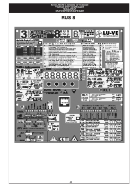
PANNELLO DI CONTROLLO
Regolatore climatico per caldaie in cascata
5
&5.:)/.)
)L SOFTWARE DI UN 2EGOLATORE CONSISTE IN VARIE &UNZIONI /GNI &UNZIONE AZIONA UNO SPECIFICO COMPONENTE O UN
GRUPPO DI COMPONENTI DI INSTALLAZIONE IN BASE ALLE PROPRIE SPECIFICHE E IMPOSTAZIONI 0ER ESEGUIRE QUESTI
COMPITI IN MANIERA OTTIMALE LE &UNZIONI DEVONO ESSERE CAPACI DI SCAMBIARSI I DATI COME IMPOSTAZIONI E
LETTURE LUNA CON LALTRA 1UESTO SCAMBIO DI DATI POSSONO AVERE LUOGO TRA &UNZIONI ALLINTERNO DI UN 2EGOLATORE
E TRA &UNZIONI IN 2EGOLATORI DIVERSI TRAMITE UNA CONNESSIONE "US ESTERNO /GNI &UNZIONE DEVE AVERE UN
INDIRIZZO UNICO PER RENDERE POSSIBILE QUESTA COMUNICAZIONE ,INDIRIZZO SPECIFICO á ASSEGNATO AUTOMATICAMENTE
DURANTE LA CONFIGURAZIONE E CONSISTE IN UN NUMERO ED UNA LETTERA ES !
)L NUMERO ECC SPECIFICA IL 2EGOLATORE PRIMO 2EGOLATORE SECONDO 2EGOLATORE ECC
3E IL 2EGOLATORE á USATO COME UNUNICA UNITÜ QUESTO NUMERO á SEMPRE 3E IL 2EGOLATORE á USATO IN UN
"US 8)" IL NUMERO á ASSEGNATO AD OGNI 2EGOLATORE DURANTE CONFIGURAZIONE DEL "US
,A LETTERA ! PRIMA &UNZIONE " SECONDA &UNZIONE ECC DESIGNA LA SPECIFICA &UNZIONE ALLINTERNO DI UN
2EGOLATORE ,E LETTERE SONO ASSEGNATE DURANTE CONFIGURAZIONE DEL 2EGOLATORE #OSØ # á LINDIRIZZO DELLA
TERZA &UNZIONE NEL PRIMO 2EGOLATORE
)N BASE AL LIVELLO DEL MENÂ SI PUÒ INTERAGIRE CON IL 2EGOLATORE CONFIGURANDO E IMPOSTANDO OGNI &UNZIONE )
LIVELLIDISPONIBILISONO
s LIVELLO DESTINATO ALLUTENTE PER LA VISUALIZZAZIONE DI TEMPERATURE E DEI SET POINT IMPOSTATI
s LIVELLO DESTINATO ALLUTENTE O AL RESPONSABILE LEGALE DELLA CENTRALE TERMICA PREVIA AUTORIZZAZIONE DELLA
!ZIENDA#OSTRUTTRICE PER CAMBIARE ALCUNE IMPOSTAZIONI DI BASE
s LIVELLO DESTINATOALLINSTALLATOREE ALLASSISTENZAAUTORIZZATADELL!ZIENDA#OSTRUTTRICE PER CONFIGURARE
EIMPOSTAREIL2EGOLATORE
,E &UNZIONI CHE SI POSSONO TROVARE SONO LE SEGUENTI
&UNZIONEh'ENERALEv !
&UNZIONEh4IPO )MPIANTOv "
&UNZIONEh#ALDAIAv # OGNI CALDAIA ALMENO AVRÜ UNA PROPRIA FUNZIONE E LETTERA BEN DISTINTA
&UNZIONEh!NOMALIEv % SARÜ POSTA DOPO LE FUNZIONI h#ALDAIAv ,A SUA PRESENZA NEL 2EGOLATORE
DIPENDERÜ DALLA CONFIGURAZIONE CHE SI á SVOLTA NELLA CONFIGURAZIONE DELLA FUNZIONE h'ENERALEv
/GNI &UNZIONE DOVRÜ ESSERE CONFIGURATA DURANTE LINSTALLAZIONE VEDI APPOSITO CAPITOLO 1UI DI SEGUITO
DAREMO QUALCHE DETTAGLIO PER LA &UNZIONE 'ENERALE E POI DAREMO UNA VISUALIZZAZIONE RAPIDA DELLE RIMANENTI
FUNZIONI VISTO CHE IN OGNI CASO IL LORO MENÂ á AMPIAMENTE SPIEGATO NEL CAPITOLO RIGUARDANTE LINSTALLAZIONE
DEL 2EGOLATORE
&UNZIONE'ENERALE
,A &UNZIONE 'ENERALE á IL COMPONENTE CHE GESTISCE LE PARTI ESSENZIALI DEL 2EGOLATORE $A QUESTA &UNZIONE SI
PUÒ CAMBIARE IL LIVELLO DEL MENÂ DI TUTTE LE ALTRE FUNZIONI SI PUÒ CONFIGURARE E IMPOSTARE IL SISTEMA DI
COMUNICAZIONE TRA LE VARIE FUNZIONI E LINSTALLATORE PUÒ EFFETTUARE UN CONTROLLO MANUALE PER VERIFICARE IL BUON
FUNZIONAMENTO DELLE CALDAIE DELLA POMPA E DEL RELá DI ALLARME
$A QUESTA FUNZIONE SI PUÒ ADOPERARE VARIE IMPOSTAZIONI GENERALI IN BASE AL LIVELLO DI ACCESSO VEDI CAP 0ER ORA CI SI LIMITA A DARE UNA RIASSUNTO DI CIÒ CHE SI PUÒ TROVARE IN QUESTA FUNZIONE
3TATODISPLAY
3I VISUALIZZANO LE INFORMAZIONI DI BASE )N QUESTA FUNZIONE á DIRETTAMENTE VISUALIZZATA DATA 'IORNO DATA E
ORA
,IVELLODIACCESSO
)L LIVELLO DI ACCESSO PERMETTE DI VISUALIZZARE PARZIALMENTE O TOTALMENTE IL MENU DEL 2EGOLATORE 1UESTO PER IL
FATTO CHE OGNI LIVELLO á DESTINATO AD UNO SPECIFICO UTILIZZATORE 0ER ENTRARE IN UN DETERMINATO LIVELLO OCCORRE
INSERIRE NELLAPPOSITO SUBMENÂ DELLA FUNZIONE GENERALE UNA COMBINAZIONE DA CARATTERI PARTICOLARE DEI
TASTI DEL PANNELLO DI CONTROLLO
!CCESSO LIVELLO UTENTE
s % POSSIBILE SOLO LA VISUALIZZAZIONE DELLE TEMPERATURE E DEI PARAMETRI CHE NON POSSONO ESSERE CAMBIATI
s 3OLO UNA PARTE DEL MENU á VISIBILE
È
,i}>ÌÀiÊV>ÌVÊ«iÀÊV>`>iÊÊV>ÃV>Ì>
•
•
•
•
•
•
Il codice di accesso è composto da qualunque combinazione dei tasti del pannello di controllo.
Accesso livello 2 (utente con autorizzazione):
Visualizzazione dei dati operativi di base. Il programma Orologio e Vacanze e le impostazioni generali
sono visualizzabili ed impostabili.
Il codice di accesso è in questo ordine: , , ,
Accesso livello 3 (Installatore e Assistenza):
Visualizzazione estesa dell’intero menu del Regolatore, con completa possibilità di configurazione;
Tutto il menu è visibile. Tutte le impostazioni e le configurazioni sono possibili.
Il codice di accesso è in questo ordine: ; ; ;
Dati di funzionamento
E’ una sub funzione con la quale si può visualizzare delle informazioni elementari del Regolatore.
Impostazioni:
• Reset parametri di fabbrica: si cancellano interamente le precedenti impostazioni e si dovrà nuovamente
configurare ogni funzione e sub funzione del Regolatore;
• Inizio e fine periodo estivo: si può impostare l’inizio e la fine del periodo estivo in base alle propie
necessità;
• Funzionamento manuale: l’installatore al termine dell’installazione, può manualmente accendere la pompa,
il relè di allarme e ogni caldaia installata. Può anche manualmente spegnerle disattivandole anche durante
le normali operazioni;
• Configurazione del bus: il bus è il collegamento tra le varie funzioni. È necessario configurarlo anche se
si prevede un solo Regolatore per il fatto che le funzioni interne devono comunque essere connesse.
Funzionamento manuale (visualizzabile al terzo livello)
• Pompa “Automatico/ acceso o spento manualmente”: si può accendere o spegnere manualmente la
pompa dell’impianto connessa al Regolatore per una verifica. Chiaramente deve essere impostato in
automatico alla fine della verifica;
• Relè di allarme “Automatico/ acceso o spento manualmente”: si può accendere o spegnere manualmente
il relè (se installato) che comanda un allarme esterno dell’impianto per una verifica. Chiaramente deve
essere impostato in automatico alla fine della verifica;
• Caldaia (con la relativa identificazione) “Automatico/ acceso o spento manualmente”: si può accendere
o spegnere manualmente la caldaia identificata per una verifica. Chiaramente deve essere impostata in
automatico alla fine della verifica.
Configurazione funzione
• Lingua: si può configurare la lingua del software che può essere l’italiano o l’inglese;
• Tipo di impianto: occorre informare che tipo di impianto si è effettuato. Ciò corrisponde anche alla
scheda che bisogna inserire sul fronte del pannello del regolatore;
• Numero di caldaie: il regolatore è predisposto per gestire un massimo di 5 caldaie. Oltre questo numero,
il regolatore già è predisposto per “dialogare” con un secondo regolatore per gestire e distribuire le
funzioni;
• Tipo Regolatore: ci sarà questo tipo di richiesta solo se abbiamo un secondo regolatore. In questo caso
occorre distingue quale regolatore è il “master” (pilota) e quale è lo “Slave”(subregolatore);
• Bus: occorre informare se è presente il bus per la comunicazione delle varie funzioni;
• Funzione anomalie: occorre informare se è necessaria una ulteriore funzione per gestire le eventuali
anomalie. In questo caso, dopo le funzioni dedicate alle caldaie, ci sarà una apposita Funzione che dovrà
essere a sua volta configurata. Vedi paragrafo dedicato.
1.2 Funzione Tipo Impianto
La Funzione “Tipo Impianto” è il vero gestore dell’impianto: controlla il base alle nostre indicazioni e
impostazioni tutte le caldaie dell’impianto. Nel caso ci fossero più di 5 caldaie, questa Funzione sarà sempre
e solo presente nel Regolatore “Master” e quindi gestirà anche le caldaie collegate al Regolatore “Slave”.
Durante la fase di configurazione è necessario indicare se si è collegato al regolatore:
• un cronotermostato modulante;
• una sonda di temperatura ambiente.
Regolatore climatico per caldaie in cascata
7
E’ necessario impostare:
• se si vuole la protezione al gelo tramite la temperatura esterna (vedi capitolo “Configurazione”);
• Il tipo di funzionamento in funzione del segnale esterno applicato al terminale n° 6 della morsettiera
interna (vedi paragrafo 5.8);
• il metodo di accensione (vedi capitolo “5”);
• la sequenza di accensione delle caldaie;
• se si vuole il Programma Orologio e Vacanze. In caso affermativo, si creeranno altre due sub funzioni per
impostare l’orario di riscaldamento e il periodo di vacanza.
Stato display
Si visualizzano le informazioni di base sullo stato di funzionamento dell’impianto.
Dati di funzionamento
E’ una sub funzione con la quale si può visualizzare delle informazioni elementari: la presenza di anomalie, il
carico richiesto e quello effettivo, la tensione d’ingresso del segnale 0÷10Vdc pr un’eventuale richiesta
esterna, ecc. Non tutte le informazioni sono visualizzabili dal 1° e dal 2° livello.
Impostazioni
L’impostazione della Funzione Tipo Impianto è decisamente molto importante e vasta. Tutti i parametri sono
già precedentemente impostati in fabbrica e l’installatore potrebbe solamente effettuare un controllo veloce,
cambiando solo alcuni di essi. Si consiglia di non cambiarli inutilmente e di focalizzare solo i parametri
principali. Per cui, rammentiamo solo questi ultimi lasciando invariati quelli rimanenti:
• Parametri di configurazione per regolare la mandata in funzione di un segnale d’ingresso 0÷10Vdc (vedi
paragrafo 5.8);
• Temperatura ambiente diurna [20°C]: precedentemente impostata a 20°C. E’ la temperatura ambiente
desiderata;
• Temperatura ambiente notturna [15°C]: precedentemente impostata a 15°C. Parametro visualizzabile se
durante la configurazione è previsto il Programma Orologio. E’ la temperatura ambiente desiderata
durante il periodo notturno;
• Temperatura ambiente vacanze [10°C]: precedentemente impostata a 10°C. . Parametro visualizzabile
se durante la configurazione è previsto il Programma Vacanze. E’ la temperatura ambiente desiderata
durante il periodo di vacanza;
• Temperatura esterna di progetto [-10°C]: precedentemente impostata a –10°C. Chiaramente, si dovrebbe
far riferimento alla temperatura di progetto della zona locale di installazione (C,D,E;…);
• Curva di compensazione [°n]: occorre impostare la curva di compensazione per il calcolo della temperatura
di mandata in base alla temperatura esterna (vedi Cap. 5);
• Post circolazione della pompa [10min]: presente se durante la configurazione della Funzione generale, si
prevede un impianto con una pompa controllata dal Regolatore (scheda impianto N°2). Precedentemente
impostata a 10 minuti, al termine della domanda di riscaldamento, la pompa rimarrà attiva per il tempo
impostato;
• Struttura edificio [leggera/media/pesante]: per riuscire a migliorare il comfort, occorre dare una
informazione sulla tipologia dell’edificio. E’ chiaro che è una valutazione basata sul volume lordo e dalla
struttura dei muri esterni, nonché dal pavimento e dal tetto.
Programma Orologio e Vacanze
Sono due sub funzioni ben distinte e la loro presenza dipende dalla impostazione della funzione e dalla
presenza del cronotermostato modulante. La loro funzione è quella di programmare l’orario di funzionamento
diurno e notturno e il periodo di vacanza. E’ chiaro che per il loro buon funzionamento, occorre una sonda
ambiente.
Funzionamento Ore e conta impulsi
E’ una sub funzione che permette di visualizzare il tempo e il numero di azionamenti della pompa dell’impianto.
Anomalie
E’ una sub funzione che permette di visualizzare e identificare le anomalie riscontrate nell’impianto. L’ultima
anomalie è datata e in ogni caso le rimanenti sono registrate.
8
Regolatore climatico per caldaie in cascata
Configurazione funzione
• Cronotermostato modulante: si può collegare al Regolatore un cronotermostato modulante. Se connesso,
si può direttamente da esso impostare il programma orario e vacanze;
• Temperatura ambiente: si può collegare al Regolatore una sonda ambiente. Questo permette un migliore
comfort e la possibilità di avere una protezione al gelo in base alla temperatura ambiente. Tale sonda
non è necessaria qualora fosse già collegato il cronotermostato modulante ;
• Numero di caldaie: il regolatore è predisposto per gestire un massimo di 5 caldaie. Oltre questo numero,
il regolatore già è predisposto per “dialogare” con un secondo regolatore per gestire e distribuire le
funzioni.
1.3 Funzione Caldaie
La Funzione “Caldaie” gestisce e identifica una sola caldaia. Per cui, sarà presente una Funzione Caldaia
specifica che identifica ogni caldaia dell’impianto. Nel Regolatore Master, si potrà visualizzare e configurare
le funzioni caldaie anche dei generatori collegati ai regolatori Slave. La funzione controlla la specifica caldaia,
in base alle regolazioni imposte dal Regolatore e dalle esigenze dell’impianto.
Stato display
Si visualizzano le informazioni di base sullo stato di funzionamento della caldaia.
Dati di funzionamento
E’ una sub funzione con la quale si può visualizzare delle informazioni elementari: la presenza di anomalie, il
carico richiesto e quello effettivo, ecc.
Funzionamento Ore e conta impulsi
E’ una sub funzione che permette di visualizzare il tempo e il numero di azionamenti della caldaia.
Anomalie
E’ una sub funzione che permette di visualizzare e identificare le anomalie riscontrate dalla caldaia. L’ultima
anomalie è datata e in ogni caso le rimanenti sono registrate.
Configurazione funzione
• Caldaia massima potenza in [kW]: si deve indicare la potenza nominale utile della caldaia;
• Caldaia minima potenza in [%]: si deve indicare la potenza minima utile in percentuale rispetto alla
potenza nominale utile della caldaia;
• Azzera contaore: la funzione caldaia ha la possibilità di registrare le ore di funzionamento. Durante la
configurazione è possibile azzerare il contaore della funzione.
1.4 Funzione Anomalie
Durante la configurazione della Funzione Generale, si può predisporre del Regolatore di una Funzione che
possa gestire le anomalie che potrebbero accadere all’impianto. E’ possibile avere questa funzione per
qualsiasi tipo e configurazione di impianto, con uno o più regolatori. E’ indispensabile anche nel caso non
venga collegato un modem esterno tramite un opportuno cavo speciale per la segnalazione automatica
delle anomalie o per l’invio automatico di una verifica periodica dell’impianto. I dettagli dell’impostazione
del modem, del numero e della intestazione del fax non sono trattati in questo manuale. Nel paragrafo
dedicato all’installazione del Regolatore, in un paragrafo si indicherà come configurare la Funzione Anomalie.
Regolatore climatico per caldaie in cascata
9
).34!,,!:)/.%
)N QUESTO CAPITOLO SI DARANNO TUTTE LE INFORMAZIONI NECESSARIE PER INSTALLARE E COMMISSIONARE IL 2EGOLATORE
!831
0RIMA DI TUTTO á DESCRITTO IL MONTAGGIO DEL 2EGOLATORE ASSIEME AI DETTAGLI DI COME COLLEGARE I VARI COMPONENTI
,A CONFIGURAZIONE DELLE VARIE &UNZIONI SONO SPIEGATE INDIVIDUALMENTE DOPO LA DESCRIZIONE DELLINSTALLAZIONE
)NFINE VERRANNO TRATTATE LE IMPOSTAZIONI TIPICHE PER OGNI &UNZIONE AL FINE DI PERMETTERE DELLE OPPORTUNE
REGOLAZIONI OCCORRENTI PER IL BUON FUNZIONAMENTO DELLIMPIANTO
3I TENGA QUESTO DOCUMENTO IN UN LUOGO ASCIUTTO E SICURO E LO SI LEGGA ATTENTAMENTE PRIMA DI COMINCIARE
LINSTALLAZIONE
#ONTATTIATE LASSISTENZA AUTORIZZATA DELL!ZIENDA#OSTRUTTRICE SE SI RISCONTRASSERO DEI PROBLEMI TECNICI
)NSTALLAZIONEDEL#ONTROLLOREDISEGUITODESCRITTAáDESTINATAALSOLOPERSONALEAUTORIZZATO
!831
!VVERTENZE
s
s
s
s
s
s
4OGLIERE LALIMENTAZIONE ELETTRICA DELLA RETE PRIMA DI PROCEDERE CON LINSTALLAZIONE
)L COLLEGAMENTO DI TERRA á POSTO LATERALMENTE AI COLLEGAMENTI DELLA FASE , E DEL NEUTRO . E DEVE ESSERE
SEMPRE COLLEGATO RISPETTANDO NEL COLLEGAMENTO LA NORMA 6IGENTE .ORMATIVA #%)
2ISPETTARE LE POLARITÜ DELLA FASE E DEL NEUTRO
)L COLLEGAMENTO DELLA FASE O DELLA TERRA DEVONO ESSERE FATTI TRAMITE GLI APPOSITI MORSETTI DEL 2EGOLATORE
!SSICURARE SALDAMENTE E ORDINATAMENTE TUTTI I CAVI TRAMITE LE FASCETTE PASSACAVO IN DOTAZIONE AL 2EGOLATORE
3) PREMA I TASTI CON LE SOLE DITA 3TRUMENTI APPUNTITI POSSONO DANNEGGIARE LA MEMBRANA DEL 2EGOLATORE
)STRUZIONIPERILPOSIZIONAMENTO
s
s
s
s
s
s
-ONTARE IL 2EGOLATORE CON LINTERFACCIA VERSO LUTENTE IN UNA LOCAZIONE FACILMENTE ACCESSIBILE
,O SI INSTALLI AD UN METRO E MEZZO DAL SUOLO PER FACILITARNE LA LETTURA SUL DISPLAY
3I TENGA CONTO DEI REQUISITI DEL 2EGOLATORE FACENDO RIFERIMENTO ALLA MASSIMA TEMPERATURA AMMISSIBILE
DELLAMBIENTE CIRCOSTANTE E ALLA MASSIMA UMIDITÜ RELATIVA PERMESSA SI VEDA LA SCHEDA TECNICA IN APPENDICE
3I PRENDA LE OPPORTUNE PRECAUZIONI PER EVITARE CHE IL 2EGOLATORE E I COLLEGAMENTI ELETTRICI ENTRINO IN
CONTATTO CON ACQUA O SPRUZZI DI SOSTANZE CHIMICHE
#OLLEGARE OGNI 2EGOLATORE ALLA RETE CON 6 E (Z INTERPONENDO UN OPPORTUNO INTERRUTTORE
#ISILIMITICONILNUMERODICAVIELOSIINSTALLIILPIÂVICINOPOSSIBILEALLECALDAIE
,ASUAUBICAZIONEDEVETENERECONTODIUNEVENTUALECOLLEGAMENTOAUN0#OAUNMODEM
)COLLEGAMENTISOPRADESCRITTIDEVONOTENERECONTODELLESPECIFICHEDEICOMPONENTISTESSI
)STRUZIONIPERILMONTAGGIO
!PERTO IL +IT SI CONTROLLI IL CONTENUTO DELLA SCATOLA 1UESTO DEVE CONTENERE IL SEGUENTE CORREDO
s
s
s
s
s
s
£ä
5N2EGOLATORE!831
4RE SCHEDE PER DISTINGUERE IL TIPO DI IMPIANTO DA INSERIRE SUL PANNELLO DEL 2EGOLATORE
5NA SONDA ESTERNA .4# CON RELATIVE ISTRUZIONI PER IL MONTAGGIO
5N SENSORE .4# A POZZETTO PER LA MANDATA E UN PEZZO DI NASTRO ADESIVO IN ALLUMINIO
5N SACCHETTO CON DELLE VITI DEI TASSELLI DA MM UN *UMPER E DELLE FASCETTE PASSACAVO 5NA MASCHERINA IN CARTONCINO PRESTAMPATA PER IL POSIZIONAMENTO DEI FORI SUL MURO % POSIZIONATA SUL
FONDO DELLA SCATOLA DEL 2EGOLARE
,i}>ÌÀiÊV>ÌVÊ«iÀÊV>`>iÊÊV>ÃV>Ì>
2.3 Inserimento della scheda “Tipo di impianto”
L’etichetta sul fronte del Regolatore ha una tasca che abilita una scheda di inserto. Si puntualizza che la
scheda N° 3, non deve essere utilizzata.
Procedere come segue:
1. Selezionare la scheda corretta in base alla tipologia dell’impianto;
2. Alzare l’etichetta sulla destra e si faccia scivolare la scheda di inserto nella tasca;
3. Rimuovere la striscia protettiva dalla metà dell’etichetta e si applichi fermamente l’etichetta per fissarla.
2.4 Montaggio del Regolatore
Il Regolatore utilizza tre viti per il montaggio. La vite nella parte superiore è usata per appendere il Regolatore
e una volta posizionato opportunamente con le due viti più basse lo si assicura al muro. Si utilizzi la mascherina
in cartoncino prestampato per determinare la posizione dei fori.
Procedere come segue:
1. Determinare l’ubicazione esatta del Regolatore e si attacchi la mascherina in cartoncino contro il muro;
2. Si facciano i tre fori nelle ubicazioni indicati sulla mascherina. La vite sopra è lontana abbastanza per far
si che il Regolatore possa essere sospeso con un po’ di gioco per posizionarlo orizzontalmente;
3. Si rimuova il piccolo coperchio posto nella parte più bassa del Regolatore;
4. Si localizzi le rimanenti due viti e si fissi il Regolatore dopo averlo allineamento;
5. Si richiudi il piccolo coperchio rimosso al punto 4.
Regolatore climatico per caldaie in cascata
11
2.5 Montaggio dei sensori e dei cavi
Si raccomanda di togliere l’alimentazione alla rete, di fare un buon collegamento a terra rispettando nel
collegamento la norma Vigente Normativa CEI.
Procedere come segue:
1. Rimuovere il piccolo coperchio posto nella parte bassa del Regolatore;
2. Focalizzare i sensori richiesti dall’impianto e si proceda al loro collegamento sulla morsettiera del
Regolatore. Si presti attenzione a collegare i vari sensori secondo le posizioni riportate nel prossimo
paragrafo;
3. Connettere tutti gli interruttori e i cavi di comunicazione al Regolatore facendo attenzione alle
caratteristichedeisensori;
4. Connettere il cavo di alimentazione alla rete (precedentemente tolta);
5. Assicurare e si controlli che tutti i cavi siano raccolti e tenuti saldamente dalle fascette date in dotazione;
6. Annotare il numero che è scritto sul coperchio grande (tra le morsettiere) che comincia con XIB e
successivamente il numero. E’ necessario annotarsi questo numero per configurare un funzione interna
del Regolatore;
7. Rimontare il piccolo coperchi nella parte bassa del Regolatore;
8. Si può dare alimentazione elettrica al Regolatore.
Attenzione: prima di effettuare i collegamenti, si deve consultare la scheda tecnica posta in
appendice per verificarne in corretto utilizzo.
2.6 Collegamento di più Regolatori per gestire più di 5 caldaie
Quando è necessario utilizzare più di un Regolatore, occorre collegarli assieme tramite un cavo schermato
come indicato in figura. In questo modo, le caldaie potranno scambiarsi i dati e potranno gestire le caldaie
collegate.
Chiaramente, occorre configurare e impostate opportunamente le funzioni interne come successivamente
indicato.
Un Regolatore dovrà funzionare come pilota e verrà indicato come “Master” mentre i rimanenti Regolatori
lavoreranno come “Slave” ovvero come subordinati. Oltre che a 5 caldaie, tutti i sensori, gli interruttori e i
carichi saranno collegati al Master. Agli Slave saranno collegate le rimanenti caldaie (sempre un massimo di
5 generatori per Regolatore) e saranno tutti collegati con il Master tramite un cavo schermato.
Il cavo schermato dovrà essere collegato ai morsetti ABS su tutti i regolatori. Se i regolatori sono parecchio
distanti tra loro, è necessario collegare il cavo schermato come un circuito ad anello. Infine, un Regolatore
deve avere inserito il Jumper JP7 che è posto appena sopra i morsetti ABS.
Attenzione: è necessario inserire sempre un Jumper a un solo Regolatore.
13 14 15 16 17 18 19 20
1 2 3 4 5
A
B
S
6
7 8 9
13 14 15 16 17 18 19 20
1 2 3 4 5
A
B
6
7 8 9
13 14 15 16 17 18 19 20
S
1 2
A
B
3 4 5
6
7 8 9
S
Il XIB bus deve essere configurato nel Regolatore Master, mentre non deve essere configurato nei Regolatori
Slave (vedi “Configurazione Funzioni”).
12
Regolatore climatico per caldaie in cascata
2.7 Descrizione dei collegamenti
SCHEMA MORSETTIERA
DESCRIZIONE DEI CONTATTI
Morsetti
Descrizione
Necessità / Tipo impianto
L–N-T
Alimentazione al regolatore (230V – 50/60Hz)
Obbligatorio
T – N’ – L’
Alimentazione alla pompa mandata impianto
Per scheda tipo impianto N°2
1–2
Allarme relè: bassa tensione “chiude” in caso di anomalia
Consigliato
3 - Common
Sensore NTC di mandata. Vedi appendice la scheda tecnica
Obbligatorio
4 - Common
Sonda NTC temperatura esterna. Vedi scheda tecnica
Obbligatorio
5 - Common
Sonda ambiente
Consigliata per un maggior comfort
6 - Common
Richiesta esterna configurabile: alla chiusura del contatto/Tensione
Non necessario
ingresso 0÷10Vdc
RS 232
Collegamento PC/Modem
Solo se si utilizza Funzione Anomalie
A–B-S
Collegamento tra regolatori con cavo schermato (bus)
Per impianti con più di 1 regolatore
7–8
Cronotermostato modulante
Non necessario
9 – 10
Generatore o caldaia N°1
Obbligatorio
11 – 12
Generatore o caldaia N°2
Obbligatorio
13 – 14
Generatore o caldaia N°3
Se previsto dall’impianto
15 – 16
Generatore o caldaia N°4
Se previsto dall’impianto
17 – 18
Generatore o caldaia N°5
Se previsto dall’impianto
JP7
Jumper: inserirne solo 1 nel caso ci fossero più di 1 Regolatore
Obbligatorio in un solo Regolatore
JP5
Configurazione hardware per il tipo di richiesta
Solo se si utilizza come richiesta esterna un
segnale 0÷10Vdc
Regolatore climatico per caldaie in cascata
13
2.8 Schema impianto
14
Regolatore climatico per caldaie in cascata
3. CONFIGURAZIONE
3.1 Configurazione di un Regolatore
Terminata l’installazione del Regolatore e assicurati tutti i suoi collegamenti elettrici, occorre configurare
tutte le sue funzioni interne seguendo il seguente percorso:
Funzione 001-A “Generale”: occorre configurare le seguenti sub funzioni:
• Configurazione.
La funzione Generale è sempre presente in un Regolatore.
Funzione 001-B “Tipo impianto”: occorre configurare le seguenti sub funzioni:
• Configurazione;
• Programma Orologio (se previsto durante la configurazione);
• Programma Vacanze (se previsto durante la configurazione).
Se è collegato al Regolatore un Cronotermostato modulante e quindi se ne indica la presenza durante la
precedente configurazione, non viene data dal Regolatore la possibilità di avere le sub funzioni “Programma
Orologio” e “Programma Vacanze” per il fatto che devono essere impostate dal Cronotermostato modulante
stesso e non è necessario installare una sonda ambiente per la stessa precedente motivazione.
Funzione 001-C/D..”Caldaia”: occorre configurare le seguenti sub funzioni:
• Configurazione.
E’ necessario configurare ogni funzione relativa ad ogni caldaia collegata al Regolatore.
Funzione 001-E..”Anomalie”: occorre configurare le seguenti sub funzioni:
• Configurazione.
La presenza di questa funzione dipende dalla configurazione della Funzione Generale alla voce “visualizzazione
anomalie”.
E’ necessaria la presenza di questa funzione anche nel caso non si preveda il collegamento di un modem
esterno, per l’invio automatico della verifica periodica dell’impianto tramite un fax o dell’invio automatico di
un fax con messaggio di errore nel caso l’impianto presenti qualche anomalia.
Se non viene prevista, in ogni caso le anomalie vengono segnalate dai LED presenti sul pannello del Regolatore
o dall’allarme relè se installato. Inoltre le anomalie, possono essere identificate all’interno delle funzioni per
il fatto che ogni funzione del Regolatore ha una sub funzione “anomalie” che ha la possibilità di segnalare e
identificareiltipodianomalia.
Avvertenza: Tutti i passi della configurazione sono di seguito descritti in dettaglio. Se si commette
un errore durante la configurazione e non si riesce a superarlo, consigliamo di entrare nella sub
funzione “Impostazioni” della Funzione Generale e di eseguire un “reset” dei parametri di fabbrica.
In questo modo, la configurazione dovrà partire dall’inizio.
Regolatore climatico per caldaie in cascata
15
3.1.1 Configurazione Funzione Generale
Visualizzata la Funzione Generale, premere il tasto per visualizzare le sub funzioni al suo interno. Se è la
prima accensione, la prima e la sola sub funzione è indicata come “Configurazione”, altrimenti scorrere con
i tasti ( )( ) per visualizzare la “Liv di accesso” ed entrare nel livello “3” (vedi capitolo 1). Uscire dalla sub
funzione e scorrere con i tasti fino a che si visualizza “Configurazione” sul display.
Entrare in questa sub funzione premendo il tasto
“Configura funzione”.
Configurazione
Configura
Funzione
Premere i tasti
. Ora verrà chiesto
per visualizzare la risposta “Sì” e confermare con il tasto .
SI
Adesso comincia la, configurazione.
Italiano
Lampeggerà sul display la lingua richiesta. Con i tasti
e poi premere conferma
selezionare “Italiano”
Scheda tipo di
impianto
Nr. x
Apparirà sul display “Scheda tipo di impianto”. Con i tasti
selezionare
“1” o “2” e premere conferma . Non scegliere il numero “3”.
Numero totale di
caldaie
(1÷5)
Apparirà sul display “Numero totale di caldaie”. Con i tasti
selezionare
il numero delle caldaie collegate al Regolatore e poi premere conferma .
Devono essere meno di 5 caldaie essendoci un solo Regolatore.
NO
Apparirà sul display “XIB bus”. Con i tasti
selezionare “No” e premere
conferma . Si seleziona “Sì” nel caso ci fossero più regolatori collegati
assieme.
SI
Apparirà sul display “Visualizzazione anomalie”. Con i tasti
selezionare
“SI” e premere conferma . E’ necessario selezionare “Sì” anche se non si
prevede una comunicazione via modem.
Estat/Inv cambio
ora automatic
SI
Apparirà sul display “Estat/Inv cambio ora automatico”. Con i tasti
selezionare “Sì” e premere conferma . In questo modo, il Regolatore si
regolerà automaticamente per il cambio stagione.
XIB Bus
Visualizzazione
anomalie
La configurazione della Funzione Generale è terminata e si dovrebbe visualizzare la sub funzione con il
giorno, la data e l’ora se è la prima volta che si configura la funzione. Scorrere con i tasti
, entrare sulla
sub funzione “Liv di accesso” e passare al terzo livello.
Successivamente uscire dal menù premendo il tasto
16
fino a visualizzare la Funzione Generale sul display.
Regolatore climatico per caldaie in cascata
3.1.2 Configurazione Funzione Tipo impianto
Scorrere con i tasti ( )( ) per visualizzare la Funzione “Tipo Impianto” e entrarvi premendo il tasto .
Scorrere con i tasti
tra le sub funzioni fino a che si visualizza “Configurazione” sul display. Dovrebbe
automaticamente visualizzarsi se è la prima installazione.
Entrare in questa sub funzione premendo il tasto
“Configura funzione”.
Configurazione
Configura
Funzione
SI
Segnale ingresso
0-10V
SI
. Ora verrà chiesto
Premere i tasti
per visualizzare la risposta “Sì” e confermare con l tasto
. Adesso comincia la configurazione.
Apparirà sul display “Segnale ingresso 0÷10V”. Con i tasti
selezionare
“Si” o “No” e premere conferma . Si seleziona “Si” per attivare la regolazione
della temperatura di mandata in funzione di un segnale di tensione esterno
compreso nel range 0÷10V. (Avvertenza: vedi paragrafo 5.8).
Cronotermostato
modulante
NO
selezionare
Apparirà sul display “Cronotermostato modulante”. Con i tasti
“Sì” o “No” e premere conferma . Si seleziona “Sì” nel caso ci fosse il
Cronotermostato modulante installato.
Protez gelo con
temp esterna
SI
Apparirà sul display “Protez gelo con temp esterna”. Con i tasti
selezionare “Sì” e premere conferma . Si seleziona “Sì” perché è una
protezione utile contro i danni causati dal gelo.
NO
Apparirà sul display “Temp ambiente”. Con i tasti
selezionare “Sì” o
“No” e premere conferma . Si seleziona “Sì” nel caso ci fosse la sonda NTC
ambiente installata. (Avvertenza: vedi nota fine configurazione!)
Temp ambiente
Colleg termin 6
Funz. diurno
Program Orologio
Interno
Program Vacanze
Interno
Metodo accension
Nr.
Sequen accension
Automatica
selezionare la funzione
Apparirà sul display “Colleg termin 6”. Con i tasti
del tasto desiderata e premere conferma . Si seleziona solo nel caso ci
fosse un interruttore installato per adempiere a questa funzione operativa.
Apparirà sul display “Program Orologio”. Con i tasti
selezionare “Interno”
o “Nessuno” e premere conferma . Si seleziona “Interno” nel caso si vuole
una sub funzione nella quale si voglia programmare il riscaldamento
settimanalmente. (Avvertenza: vedi nota fine configurazione!)
Apparirà sul display “Program Vacanze”. Con i tasti
selezionare “Interno”
o “Nessuno” e premere conferma . Si seleziona “ Interno” nel caso si vuole
una sub funzione nella quale si voglia programmare le vacanze (ci sono 8
impostazioni possibili). (Avvertenza: vedi nota fine configurazione!)
Apparirà sul display “Metodo accension”. Con i tasti
selezionare da 1 a
3 e premere conferma . Vedere il capitolo 5. del Regolatore per decidere il
tipo di accensione desiderata.
Apparirà sul display “Sequen accension”. Con i tasti
selezionare
“Automatica” e premere conferma . Permetterà di ripartire l’usura
omogeneamente su tutte le caldaie in base alle ore di funzionamento.
Selezionando “Fissa”, le caldaie avranno sempre lo stesso ordine di accensione
che rispetta i collegamenti elettrici.
Regolatore climatico per caldaie in cascata
17
Protezione
bloccaggio
SI
Apparirà sul display “Protezione bloccaggio”. Con i tasti
selezionare
“Sì” e premere conferma . Permetterà di evitare il bloccaggio della pompa
collegata al Regolatore a causa di lunghi periodi di inattività.
Azzeramento
contaore
NO
selezionare
Apparirà sul display “Azzeramento contaore”. Con i tasti
“No” e premere conferma . In questo modo, non verranno persi i dati
memorizzati per passati utilizzi.
La configurazione della Funzione Tipo impianto è terminata e si dovrebbe
visualizzare la sub funzione “Configurazione”. Scorrere con i tasti
, entrare
sulla sub funzione “Program Orologio” “Program Vacanze” e impostare il
tutto.
Configurazione
Successivamente uscire dal menù premendo il tasto
display.
fino a visualizzare la Funzione Tipo impianto sul
Avvertenza: Se è installato il “Cronotermostato modulante”, durante la configurazione non
appariranno “Temp ambiente”, “Program Orologio” e “Program Vacanze”.
3.1.3 Configurazione Funzione Caldaia
Scorrere con i tasti ( )( ) per visualizzare la Funzione “Caldaia” e entrarvi premendo il tasto . Scorrere
con i tasti
tra le sub funzioni fino a che si visualizza “Configurazione” sul display. Dovrebbe
automaticamente visualizzarsi se è la prima installazione.
Entrare in questa sub funzione premendo il tasto
“Configura funzione”.
Configurazione
Configura
Funzione
SI
. Ora verrà chiesto
Premere i tasti
per visualizzare la risposta “Sì” e confermare con il tasto
. Adesso comincia la configurazione.
Caldaia massima
potenza
(KW)
Apparirà sul display “Caldaia massima potenza”. Con i tasti
impostare
la potenza massima in [kW] della caldaia relativa alla funzione e premere
conferma .
Caldaia minima
potenza
Apparirà sul display “Caldaia minima potenza”. Con i tasti
impostare la
potenza minima in [%] rispetto alla massima, della caldaia relativa alla funzione
e premere conferma .
(%)
Azzera contaore
NO
Apparirà sul display “Azzera contaore”. Con i tasti
premere conferma .
selezionare “No” e
La configurazione della Funzione Caldaia è terminata e si dovrebbe visualizzare la sub funzione
“Configurazione”. Successivamente uscire dal menù premendo il tasto fino a visualizzare la Funzione
Caldaia sul display.
Scorrere con i tasti ( )( ) per visualizzare la successiva Funzione “Caldaia” e entrarvi premendo il tasto .
Scorrere con i tasti
tra le sub funzioni fino a che si visualizza “Configurazione” sul display. Dovrebbe
automaticamente visualizzarsi se è la prima installazione. Ripetere la configurazione sopra descritta.
Tale configurazione deve ripetersi per tutte le Funzioni relative alle caldaie collegate.
18
Regolatore climatico per caldaie in cascata
3.1.4 Configurazione Funzione Anomalie
Durante la configurazione della Funzione Generale, si può predisporre del Regolatore di una Funzione che
possa gestire le anomalie che potrebbero accadere all’impianto. E’ possibile avere questa funzione per
qualsiasi tipo e configurazione di impianto, con uno o più regolatori.
I dettagli della impostazione del modem, del numero e della intestazione del fax non sono trattati in questo
manuale. In questo paragrafo, impostiamo opportunamente la Funzione Generale e configuriamo la Funzione
Anomalie.
Vogliamo sottolineare un passaggio importante della configurazione della Funzione Generale:
Visualizzazione
anomalie
SI
Quando apparirà sul display “Visualizzazione anomalie”. Con i tasti
selezionare “Sì” e premere conferma . Infatti, si prevede il collegamento ad
un modem, la Funzione Anomalie verrà creata presso il Regolatore principale.
Occorre configurare la Funzione Anomalie dopo la configurazione della Funzione Generale, del Tipo impianto,
delle Caldaie.
Scorrere con i tasti ( )( ) per visualizzare la Funzione “Anomalie” sul display
tra le sub funzioni
e entrarvi premendo il tasto . Scorrere con i tasti
fino a che si visualizza “Configurazione” sul display. Dovrebbe
automaticamente visualizzarsi se è la prima installazione.
Configurazione
Configura
funzione
SI
Entrare in questa sub funzione premendo il tasto . Ora verrà chiesto
“Configura funzione”. Premere i tasti
per visualizzare la risposta “Sì” e
confermare con l tasto . Adesso comincia la configurazione.
SI
Apparirà sul display “Messaggio fax”. Con i tasti
selezionare “Sì” e
premere conferma . In questo modo si attiva la funzione che prevede l’invio
di un fax nel caso ci fosse una anomalia al sistema (vedi avvertenze).
Messaggio fax
Verifica sistema
con fax
SI
Apparirà sul display “Verifica sistema con fax”. Con i tasti
selezionare
“Sì” e premere conferma . In questo modo, settimanalmente, il Regolatore
invierà un fax (lunedì mattina alle ore 7.00) con il quale notifica la buona
funzionalità del sistema.
La configurazione della Funzione Anomalie è terminata e si dovrebbe visualizzare “Configurazione” sul
display.
Successivamente uscire dal menù premendo il tasto fino a visualizzare la Funzione Generale sul display.
Avvertenze: La Funzione Anomalie può essere impostata come sopra descritto anche senza il
collegamento modem. In questo caso, durante la configurazione, quando apparirà sul display
“Messaggio fax” occorre selezionare “No” per terminare la configurazione.
Il Regolatore avrà in ogni caso una Funzione Anomalie ma non sarà possibile inviare nessun fax.
Si può così ritenere conclusa la configurazione di un Regolatore che abbia collegato al massimo 5 caldaie.
Regolatore climatico per caldaie in cascata
19
3.2 Configurazione di più Regolatori collegati assieme
Terminata l’installazione dei Regolatori e assicurati tutti i loro collegamenti elettrici, occorre configurare
tutte le funzioni interne. E’ già stato collegato al Master tutte le sonde e i carichi esterni. Inoltre è già stato
collegato il cavo schermato tra i regolatori e inserito il jumper in uno dei regolatori. Alimentati, occorre
configurare il Regolatore Master seguendo questo percorso:
Funzione 001-A “Generale”: occorre configurare le seguenti sub funzioni:
• Configurazione (durante la configurazione si prevede il collegamento XIB Bus e la designazione del
regolatore come Master);
• Configurazione XIB Bus.
La Funzione Generale è sempre presente in un Regolatore. Nel Regolatore Master, saranno presenti anche
le Funzioni generali dei regolatori Slave e le funzioni delle caldaie ad essi collegate. La configurazione di tutti
i regolatori e delle funzioni caldaie, può essere eseguita direttamente dal regolatore Master senza dover
ripeterla ad ogni regolatore Slave.
Funzione 001-B “Tipo impianto”: occorre configurare le seguenti sub funzioni:
• Configurazione;
• Programma Orologio (se previsto durante la configurazione);
• Programma Vacanze (se previsto durante la configurazione).
Se è collegato al Regolatore un Cronotermostato modulante e quindi se ne indica la presenza durante la
precedente configurazione, non viene data dal Regolatore la possibilità di avere le sub funzioni “Programma
Orologio” e “Programma Vacanze” per il fatto che devono essere impostate dal Cronotermostato modulante
stesso e non è necessario installare una sonda ambiente per la stessa precedente motivazione.
Funzione 001-C/D..”Caldaia”: occorre configurare le seguenti sub funzioni:
• Configurazione.
E’ necessario configurare ogni funzione relativa ad ogni caldaia collegata al Regolatore. Dal Regolatore
Master è possibile configurare le funzioni relative alle caldaie collegate ai regolatori Slave.
Funzione 001-E..”Anomalie”: occorre configurare le seguenti sub funzioni:
• Configurazione.
La presenza di questa Funzione dipende dalla configurazione della Funzione Generale alla voce
“Visualizzazione anomalie”.
E’ necessaria la presenza di questa Funzione anche nel caso non si preveda il collegamento di un modem
esterno, per l’invio automatico della verifica periodica dell’impianto tramite un fax o l’invio automatico di un
fax con messaggio di errore nel caso l’impianto presenti qualche anomalia.
Se non viene prevista, in ogni caso le anomalie vengono segnalate dai LED presenti sul pannello del Regolatore
o dall’allarme relè se installato. Inoltre le anomalie, possono essere identificate all’interno delle funzioni per
il fatto che ogni Funzione del Regolatore ha una sub funzione “anomalie” che ha la possibilità di segnalare
e identificare il tipo di anomalia.
Avvertenza: Tutti i passi della configurazione sono di seguito descritti in dettaglio. Se si commette
un errore durante la configurazione e non si riesce a superarlo, consigliamo di entrare nella sub
Funzione “Impostazioni” della Funzione Generale e di eseguire un “reset” dei parametri di fabbrica.
In questo modo, la configurazione dovrà partire dall’inizio.
20
Regolatore climatico per caldaie in cascata
3.2.1 Configurazione Funzione Generale per Regolatore Master
Visualizzata la Funzione Generale, premere il tasto per visualizzare le sub funzioni al suo interno. Se è la
prima accensione, la prima e la sola sub funzione è indicata come “Configurazione”, altrimenti scorrere con
i tasti ( )( ) per visualizzare “Liv di accesso” ed entrare nel livello “3” (vedi capitolo 1). Uscire dalla sub
funzione e scorrere con i tasti fino a che si visualizza “Configurazione” sul display.
Entrare in questa sub funzione premendo il tasto
“Configura Funzione”.
Configurazione
Configura
Funzione
SI
. Ora verrà chiesto
Premere i tasti
per visualizzare la risposta “Sì” e confermare con il tasto
. Adesso comincia la configurazione.
Italiano
Lampeggerà sul display la lingua richiesta. Con i tasti
e poi premere conferma
Scheda tipo di
impianto
Nr. XX
Apparirà sul display “Scheda tipo di impianto”. Con i tasti
selezionare
“1” o “2” e premere conferma . Non scegliere il numero “3”.
Numero totale di
caldaie
Nr. 6
Apparirà sul display “Numero totale di caldaie”. Con i tasti
selezionare
il numero delle caldaie collegate ai regolatori e poi premere conferma .
Devono essere almeno 6 caldaie.
Regolatore
Apparirà sul display “Regolatore”. Con i tasti
impostare il Regolatore
come Master e poi premere conferma . Infatti il Regolatore in cui si effettua
la configurazione è il Master.
Master
XIB bus
SI
Visualizzazione
anomalie
SI
Estat/Inv cambio
ora automatic
SI
selezionare “Italiano”
Apparirà sul display “XIB bus”. Con i tasti
selezionare “Sì” e premere
conferma . In questo modo si crea una nuova sub funzione “Configurazione
XIB bus” nella Funzione Generale che dovrà poi essere subito configurata al
termine della configurazione.
selezionare
Apparirà sul display “Visualizzazione anomalie”. Con i tasti
“Si” e premere conferma . E’ necessario selezionare “Sì” anche se non si
prevede una comunicazione via modem.
Apparirà sul display “Estat/Inv cambio ora automatico”. Con i tasti
selezionare “Sì” e premere conferma . In questo modo, il Regolatore si
regolerà automaticamente per il cambio stagione.
La configurazione della Funzione Generale è terminata e si dovrebbe visualizzare la sub funzione con il
giorno, la data e l’ora se è la prima volta che si configura la Funzione. Scorrere con i tasti
, entrare sulla
sub funzione “Liv di accesso” e passare al terzo livello.
Entrati al terzo livello uscire dalla sub funzione premendo , ancora all’interno della Funzione Generale,
premere i tasti
fino a visualizzare la sub funzione “Configurazione XIB bus” sul display.
Regolatore climatico per caldaie in cascata
21
3.2.2 Configurazione della sub funzione “Configurazione XIB Bus”
Prima di configurare il Bus, occorre aver trascritto in un foglio a parte, il numero PIN che identifica tutti i
regolatori collegati assieme. E’ il numero che è scritto su una etichetta posta sul coperchio grande del
regolatore che comincia per XIB XXXXX.
XIB24191
Con “Configurazione XIB bus” visualizzato sul display, entrare in questa sub
funzione premendo il tasto .
Configurazione
XIB bus
Seguire attentamente in successione tutti i passi della configurazione.
Apparirà sul display “XIB bus da configurare”. Con i tasti
menu fino a quando apparirà “Numero di Regolatori”.
XIB bus da
configurare
Numero di
regolatori
Nr. 2
Visualizzato “Numero di regolatori” sul display, premere il tasto . Con i tasti
selezionare il numero di regolatori e poi premere conferma . Devono
essere almeno 2 regolatori. Il numero indicato terminerà di lampeggiare una
volta confermato.
Con i tasti
scorrere il menu fino a quando apparirà “Regolatori 001 XIB
bus numero 00002” sul display e premere il tasto . La prima cifra lampeggerà.
Con i tasti
selezionare il numero della prima cifra e poi si prema conferma
. Poi lampeggerà la seconda cifra che dovrà essere impostata come
precedentemente descritto e così via per tutte le altre: si deve comporre il
codice PIN che identifica il primo Regolatore (in questo caso il Master).
Regolatore 001
XIB numero
XX
Terminato di comporre il codice PIN del primo Regolatore, con i tasti
scorrere il menu fino a quando apparirà “Regolatore 002 XIB bus numero
00002” sul display e premere il tasto . La prima cifra lampeggerà. Con i tasti
selezionare il numero della prima cifra e poi si prema conferma . Poi
lampeggerà la seconda cifra che dovrà essere impostata come
precedentemente descritto e così via per tutte le altre: si deve comporre il
PIN che identifica il secondo Regolatore (in questo caso uno Slave). E così via
per tutti i regolatori dell’impianto collegati al Master.
Regolatore 002
XIB numero
YY
Configurare
XIB bus
scorrere il
SI
Terminato di comporre tutti i codici PIN di tutti i regolatori, con i tasti
scorrere il menu fino a quando apparirà “Configurare XIB bus No” sul display
e premere il tasto . Comincerà a lampeggiare “No”. Premere i tasti
per visualizzare la risposta “Sì” e confermare con il tasto .
Scorrere con i tasti
fino a visualizzare “Configurazione completa” sul
display. La configurazione del Bus è terminata.
Avvertenza: se non dovesse essere visualizzata visualizzare “Configurazione completa” sul display,
è necessario controllare il buon collegamento dei regolatori, verificare ed eventualmente ripetere
la configurazione sopra descritta e assicurarsi che il numero di regolatori sia compatibile con il
numero di caldaie che sono state impostate durante la configurazione della Funzione Generale.
22
Regolatore climatico per caldaie in cascata
3.2.3 Configurazione Funzione “Tipo impianto”
Si ripete quanto già descritto al paragrafo precedente. Infatti la sua configurazione non varia in base al
numero di regolatori.
3.2.4 Configurazione Funzione “Caldaia”
Nel Regolatore Master, vengono visualizzate tutte le funzioni relative alle caldaie dell’impianto comprese
quelle collegate ai regolatori Slave opportunamente identificate secondo quanto descritto durante il primo
capitolo. Si può configurarle direttamente dal Regolatore Master.
Per la loro configurazione, si ripete quanto già descritto al paragrafo precedente. Infatti la loro configurazione
non varia in base al numero di regolatori.
3.2.5 Configurazione Funzione “Anomalie”
Si ripete quanto già descritto al paragrafo precedente. Infatti la sua configurazione non varia in base al
numero di regolatori.
3.2.6 Configurazione Funzione “Generale” dei regolatori Slave
Il Regolatore Master, ha a disposizione nel suo menù, anche le funzioni generali degli altri regolatori
opportunamente identificati secondo quanto descritto durante il primo capitolo. Anche queste funzioni
possono essere configurate direttamente dal Regolatore Master e la loro configurazione è uguale a quella
precedentemente descritta.
Durante la configurazione, vogliamo sottolineare i seguenti passaggi:
- Apparirà sul display “Scheda tipo di impianto”. Con i tasti
selezionare “1” o “2” e premere conferma
. Non scegliere il numero “3”. Ad ogni modo, deve essere uguale al Master;
- Apparirà sul display “Numero totale di caldaie”. Con i tasti
selezionare solo il numero delle caldaie
collegate al Regolatore Slave e poi premere conferma . Devono essere meno di 5 caldaie;
- NON apparirà sul display “XIB bus” in quanto è già stato previsto e configurato nel Master;
- NON apparirà sul display “Visualizzazione anomalie” in quanto è già stata configurata nel Master.
Si può così ritenere conclusa la configurazione di un Regolatore collegato assieme ad altri regolatori per
gestire più di 5 caldaie.
Regolatore climatico per caldaie in cascata
23
-%.5%)-0/34!:)/.)$%,2%'/,!4/2%
)L -ENÂ DEL 2EGOLATORE á SUDDIVISO IN TRE LIVELLI /GNI LIVELLO á DESTINATO AD UNO SPECIFICO UTILIZZATORE ED á
ACCESSIBILE TRAMITE UNA SUB FUNZIONE PRESENTE NEL MENU DELLA &UNZIONE 'ENERALE
)LPRIMOEILSECONDOLIVELLOSONODESTINATIALLUTILIZZATOREINPARTICOLARE
PRIMOLIVELLO ACCESSIBILE ALLUTILIZZATORE .ON á POSSIBILE NESSUNA IMPOSTAZIONE MA á POSSIBILE VISUALIZZARE
ALCUNE IMPOSTAZIONI E TEMPERATURE
SECONDOLIVELLO ACCESSIBILE DALLUTILIZZATORE PREVIAAUTORIZZAZIONEDELL!ZIENDA#OSTRUTTRICE 3ONO
POSSIBILIALCUNEIMPOSTAZIONIDIBASE
TERZOLIVELLO ACCESSIBILE AL SOLO INSTALLATORE E TECNICO AUTORIZZATO DELLASSISTENZA ³ A DISPOSIZIONE UN
GRANDEMENÂEDáPOSSIBILEIMPOSTAREQUALSIASIPARAMETRO0ERTANTOáNECESSARIOPRESTAREMOLTA
ATTENZIONE ALLE IMPOSTAZIONI CHE DEVONO ESSERE ESEGUITE
,E IMPOSTAZIONE CHE DI SEGUITO VERRANNO DESCRITTE FANNO RIFERIMENTO AL SOLO TERZO LIVELLO )N OGNI CASO
VERRANNO SEGNALATE LE SUB FUNZIONI ACCESSIBILI AL PRIMO E AL SECONDO LIVELLO )NFINE TRAMITE O INDICHEREMO
SE I PARAMETRI DELLA SUB FUNZIONE SONO PRESENTI RISPETTIVAMENTE AL o O AL o LIVELLO
6ISTO IL GRANDE MENÂ A DISPOSIZIONE E LA COMPLICANZA DI ALCUNI PARAMETRI IL 2EGOLATORE á GIÜ STATO PREIMPOSTATO
IN FABBRICA )N QUESTO MODO LINSTALLATORE POTRÜ CONCENTRARSI SOLO PER ALCUNE IMPOSTAZIONI CHE VERRANNO
OPPORTUNAMENTE EVIDENZIATE DURANTE IL SEGUITO
!VVERTENZAIPARAMETRICHENONCONSIGLIAMODICAMBIARERISPETTOALLAIMPOSTAZIONEDIFABBRICA
SONOSEGNATIDADUEPUNTIESCLAMATIVI
,E SUB FUNZIONI SONO INDICATE CON LA FRECCIA 0ER ENTRARE LE MENU DELLA SUB FUNZIONE PREMERE IL TASTO E
SCORRERE IL SUB MENU CON I TASTI
0ER VARIARE IL PARAMETRO OVE POSSIBILE PREMERE IL TASTO VARIARLO CON
I TASTI
E CONFERMARE PREMENDO Ó{
,i}>ÌÀiÊV>ÌVÊ«iÀÊV>`>iÊÊV>ÃV>Ì>
4.1 Funzione Generale
Stato display (visualizzabile in tutti i livelli)
Si visualizzano le informazioni di base. In questa funzione è direttamente visualizzata data: Giorno, data e
ora.
E’ impostabile solo dal 2° e dal 3° livello.
Livello di accesso (visualizzabile in tutti i livelli)
E’ una sub funzione con la quale si può accedere ai vari livelli inserendo una opportuna chiave di accesso.
E’impostabileintuttiilivelli.
Dati di funzionamento (visualizzabile in tutti i livelli)
E’ una sub funzione con la quale si può visualizzare delle informazioni elementari. Non tutte le informazioni
sono visualizzabili dal 1° e dal 2° livello:
- Tipo/Versione: viene visualizzato il tipo e la versione del Regolatore (*
e**);
Tipo/Versione
AX5200SQ-M
Modem non trovato
- Modem: indica lo stato di collegamento con il modem (* e **);
- XIB Numero: indica il codice di identificazione del Regolatore;
- Comunicazione caldaia: indica lo stato di collegamento con le caldaie;
- Termostato Ricevuto: indica lo stato di collegamento con il termostato;
XIB Numero XXXXX
Impostazioni (visualizzabile al terzo livello)
Verrà visualizzato il “Reset parametri di fabbrica NO”. Se si seleziona “SI”, occorre configurare il regolatore
nuovamente.
Inizio periodo
estivo
Marzo
- Inizio periodo estivo: si imposta in quale mese (al terzo fine settimana)
il Regolatore effettua il cambio automatico di stagione. Impostabile da
gennaio a dicembre;
Fine periodo
estivo
Ottobre
- Fine periodo estivo: si imposta in quale mese (al terzo fine settimana) il
Regolatore effettua il cambio automatico di stagione. Impostabile da
gennaio a dicembre;
Tipo di chiamata
- Tipo chiamata “Impulsi/Toni”: si imposta il tipo di comunicazione tra
Regolatore e Modem;
Toni
- Velocità di trasmissione diretta: si imposta la velocità di comunicazione
tra Regolatore e modem;
Velocità di tras
diretta
Nr. squilli prima
della risposta
2
- Numero di squilli prima della risposta: si imposta il numero di squilli,
dopo i quali il modem risponda alla chiamata;
Funzionamento manuale (visualizzabile al terzo livello)
Pompa
Automatico
- Pompa “Automatico/ acceso o spento manualmente”: si può accendere
o spegnere manualmente la pompa dell’impianto connessa al
Regolatore per una verifica. Chiaramente deve essere impostato in
automatico alla fine della verifica;
Regolatore climatico per caldaie in cascata
25
Relè allarme
Automatico
Caldaia 1
Automatico
- Relè di allarme “Automatico/ acceso o spento manualmente”: si può
accendere o spegnere manualmente il relè (se installato) che comanda
un allarme esterno dell’impianto per una verifica. Chiaramente deve
essere impostato in automatico alla fine della verifica;
- Caldaia (con la relativa identificazione) “Automatico/ acceso o spento
manualmente”: si può accendere o spegnere manualmente la caldaia
identificata per una verifica. Chiaramente deve essere impostata in
automatico alla fine della verifica.
Configurazione XIB bus (visualizzabile al terzo livello)
Chiaramente la sub funzione è presente solo nel caso fosse stata prevista durante la configurazione della
Funzione. E’ evidente che è necessaria solo se il Regolatore è collegato assieme ad altri regolatori per
gestire più di 5 caldaie. Essendo già stata trattata durante il paragrafo “Configurazione”, vi rimandiamo ai
paragrafi precedenti.
Configurazione (visualizzabile al terzo livello)
In questa sub funzione, si configura la Funzione Generale. Essendo già stata trattata durante la
“Configurazione”, vi rimandiamo ai paragrafi precedenti.
4.2 Funzione Tipo Impianto
Stato display (visualizzabile in tutti i livelli)
Si visualizzano le informazioni di base. In questa funzione è direttamente visualizzata lo stato di funzionamento
dell’impianto in quel preciso momento.
Dati di funzionamento (visualizzabile in tutti i livelli)
E’ una sub funzione con la quale si può visualizzare delle informazioni elementari. Non tutte le informazioni
sono visualizzabili dal 1° e dal 2° livello:
- Anomalie: indica la presenza di anomalie nell’impianto (* e **);
Anomalia
°C
- Temperatura esterna: indica la temperatura rilevata dalla sonda esterna
in°C (* e **);
Temp ambiente
regolazione
20 °C
- Temperatura ambiente regolata: indica la regolazione della temperatura
ambiente in °C;
Temp mandata
°C
- Temperatura di mandata: indica la temperatura rilevata dalla sensore
di mandata in °C (* e **);
90 °C
- Temperatura di mandata regolata: indica la regolazione della
temperatura di mandata in °C;
Carico
effettivo
%
- Carico effettivo: indica il carico dato in quel momento dall’impianto in
%;
Carico
richiesto
%
- Carico richiesto: indica il carico richiesto in quel momento all’impianto
in %;
Carico
effettivo
kW
- Carico effettivo: indica il carico dato in quel momento dall’impianto in
kW;
Temp esterna
Temp mandata
regolazione
26
Regolatore climatico per caldaie in cascata
Carico
richiesto
kW
- Carico richiesto: indica il carico richiesto in quel momento
all’impianto in kW;
Caldaia N°
carico rich
kW
- Caldaia N° carico richiesto: indica il carico richiesto in quel momento
alla caldaia N° in kW;
Caldaia N°+1
carico rich
kW
- Caldaia N°+1 carico richiesto: indica il carico richiesto in quel
momento alla caldaia N°+1 in kW
Sequen caldaia
X-Y
A
- Sequenza caldaia: indica la sequenza delle caldaie;
Impostazioni (visualizzabile al secondo e al terzo livello)
E’ la sub funzione che determina l’impostazione dell’impianto. Tutti i parametri visualizzabili sono impostabili.
E’ accessibile al secondo livello solo per i primi tre parametri.
Temp ambiente
diurna
20 °C
Temp ambiente
notturna
15 °C
Temp ambiente
vacanze
10 °C
- Temperatura ambiente diurna [°C]: si imposta la temperatura
ambiente desiderata durante le ore diurne (**);
- Temperatura ambiente notturna [°C]: si imposta la temperatura
ambiente desiderata durante le ore notturne(**). Parametro
visualizzabile se durante la configurazione è previsto il Programma
Orologio;
- Temperatura ambiente vacanze [°C]: si imposta la temperatura
ambiente desiderata durante i periodi di vacanze(**).Parametro
visualizzabile se durante la configurazione è previsto il Programma
Vacanze;
20 °C
- Temperatura esterna punto fisso [°C]: si imposta la temperatura
esterna che normalmente coincide con la temperatura ambiente
richiesta durante il funzionamento diurno;
Temp mandata
punto fisso
20 °C
- Temperatura di mandata punto fisso [°C]: si imposta la temperatura
minima di mandata che normalmente coincide con la temperatura
ambiente richiesta durante il funzionamento diurno;
Temp esterna
di proget
-10 °C
- Temperatura esterna di progetto [°C]: è la temperatura esterna che
sisupponeminima.Variainbaseallalocalitàedèutilizzatadaiprogettisti
per il calcolo delle dispersioni termiche;
Temp mandata
di proget
80 °C
Temp esterna
punto fisso
Curva compensaz
1,33
- Temperatura di mandata di progetto [°C]: si imposta la temperatura
di mandata impianto;
- Curva di compensazione: il sistema lavora con temperatura scorrevole.
Con questo parametro, si imposta la pendenza delle semirette (vedi
Cap. 5);
Regolatore climatico per caldaie in cascata
27
Temp mandata
minima
1 °C
- Temperatura di mandata minima [°C] (!!): si imposta la minima temperatura di mandata. E’ attiva solo quando l’impianto è in funzionamento;
Temp mandata
massima
90 °C
- Temperatura di mandata massima [°C]: si imposta la massima temperatura di mandata. E’ attiva solo quando l’impianto è in funzionamento;
Temp mandata
margine
ØK
Protezione gelo
Tmin mand
20 °C
- Protezione gelo temperatura minima mandata [°C]: in condizione di
funzionamento per protezione gelo (sia a causa della temperatura esterna o ambiente o di mandata), si imposta la temperatura minima di
mandata;
Limite Riscald
Tempo rilev
24 h
- Limite riscaldamento tempo rilevamento [h] (!!): è il periodo di tempo,
nel quale il Regolatore fa poi la media della temperatura esterna, per
poi determinare il limite di riscaldamento. (vedi Cap. 5);
Limite Riscal
salto term
-2K
- Limite riscaldamento salto termico [K] (!!): è un salto termico che viene
utilizzato per determinare il limite riscaldamento (vedi Cap. 5);
Post circolazione
pompa
10 min
- Post circolazione pompa [minuti]: dopo lo spegnimento del riscaldamento, la pompa rimane in funzione per il tempo impostato;
Struttura Edif
- Struttura edificio [leggera/media/pesante]: occorre per cui indicare la
massa dell’edificio. Un parametro utile, potrebbe essere il volume lordo.
media
28
- Temperatura di mandata margine [K] (!!): si imposta il margine ammesso rispetto alla temperatura di mandata;
Prerisc Temp Amb
Tempo Min
15 min
- Tempo minimo di preriscaldamento ambiente [minuti] (!!): tempo
minimo di anticipo riscaldamento rispetto al programma orologio;
Prerisc Temp Amb
Tempo Max
360 min
- Tempo massimo di preriscaldamento ambiente [minuti] (!!): tempo
massimo di anticipo riscaldamento rispetto al programma orologio;
Fattore prerisc
ambiente
30 min/K
- Fattore ambiente per preriscaldamento [min/K] (!!): coefficiente utilizzato per calcolare il preriscaldamento in base alla temperatura ambiente
(vedi Cap. 3);
Fattore prerisc
esterno 0,02 min/K
- Fattore esterno per preriscaldamento [n/K] (!!): coefficiente utilizzato
per calcolare il preriscaldamento in base alla temperatura esterna;
- Salto termicodiprogetto[K](!!):Compensazionenotturna(vediCap.5)
- Salto termicomassimo(!!)fattoredicompensazionenotturna(vediCap.5):
- Carico richiesto Fattore – P [%](!!):
- Carico richiestoFattore–I[%](!!):
- Carico richiesto Fattore – D [%](!!):
Regolatore climatico per caldaie in cascata
Sequenza caldaia
ritardo
3 min
- Ritardo sequenza caldaia [minuti] (!!): durante il funzionamento in
sequenza, è il periodo di tempo lo spegnimento e l’accensione di due
caldaie caldaia;
- Errore contattobruciatore[minuti](!!):
- Cambio programma: ritardo OFF [h] (!!): tempo di ritardo alla chiusura
del terminale 6;
Temp mandata
Salto term
- Salto termico temperatura mandata [K] (!!): massimo salto termico
negativo ammesso della temperatura di mandata rispetto al valore di
setpoint;
Temp max Risc
mandata
60 min
- Tempo massimo riscaldamento mandata [minuti]: tempo massimo per
raggiungere la temperatura di setpoint (meno il salto termico
temperatura di mandata).
Programma Orologio (visualizzabile in tutti i livelli se previsto)
E’ impostabile al secondo e al terzo livello. E’ semplice e intuibile: è possibile impostare tutti i giorni della
settimana. Ogni giorno ha la possibilità di impostare una o due fasce orario per il funzionamento diurno,
ognuna con un orario di inizio e di fine. Tra le due fasce, il Regolatore prevede il funzionamento notturno.
Gi
06:30-12:00
19:00-23:00
Nell’esempio soprastante, il giorno è il giovedì. Si prevede il funzionamento diurno tra le 6.30 e le 12.00 e
tra le 19.00 e le 23. Mentre tra le 0.00 e le 6.30, tra le 12.00 e le 19.00 e tra le 23.00 e le 24.00 il funzionamento
è notturno.
Programma Orologio (visualizzabile in tutti i livelli se previsto)
E’ impostabile al secondo e al terzo livello. E’ semplice e intuibile: è possibile impostare fino a 8 periodi di
vacanze completamente indipendenti tra loro. In questo periodo, il funzionamento vacanze durerà fino alla
mezza notte dell’ultimo giorno impostato.
1:
20-12-2003
al 08-01-2004
Nell’esempio soprastante, si prevede che il periodo vacanze cominci il 20 dicembre fino al 8 gennaio compresi.
Dalle ore 0.00 del giorno 9 gennaio, il sistema ritornerà alle normali operazioni di funzionamento.
Funzionamento Ore Conta impulsi (visualizzabile al terzo livello)
Questa sub funzione, ha solo il compito di visualizzare le ore di funzionamento e il numero di volte che è
stata azionata la pompa dell’impianto.
Pompa:
35h
18I
Nell’esempio soprastante, viene visualizzato un tempo di funzionamento di 35 ore, in 18 azionamenti.
Anomalie (visualizzabile in tutti i livelli)
Questa sub funzione è semplice e intuibile e ha il compito di segnalare se sono presenti delle anomalie
nell’impianto tramite lo stato display, identificandole e indicando la data dell’anomalia. E’ possibile visualizzare
ultime 10 le anomalie registrate ed è possibile cancellarle.
Configurazione (visualizzabile al terzo livello)
In questa sub funzione, si configura la Funzione Tipo impianto. Essendo già stata trattata durante la
“Configurazione”, vi rimandiamo al paragrafo precedente.
Regolatore climatico per caldaie in cascata
29
4.3 Funzione Caldaia
Per ogni caldaia collegata, è presente una relativa funzione. Anche se ci sono più regolatori, tutte le funzioni
relative a tutte le caldaie, sono visualizzabili e configurabili direttamente al Regolatore Master.
Stato display (visualizzabile in tutti i livelli)
Si visualizzano le informazioni di base. In questa funzione è direttamente visualizzata lo stato di funzionamento
della caldaia in quel preciso momento.
Dati di funzionamento (visualizzabile in tutti i livelli)
Anomalia
- Anomalia: indica e identifica la presenza di anomalie;
Carico
richiesto
%
- Carico richiesto: indica il carico richiesto in quel momento alla caldaia
in %;
Carico
effettivo
%
- Carico effettivo: indica il carico dato in quel momento dalla caldaia in
%;
Carico
richiesto
kW
- Carico richiesto: indica il carico richiesto in quel momento alla caldaia
in kW;
Carico
effettivo
kW
- Carico effettivo: indica il carico dato in quel momento dalla caldaia in
kW.
Funzionamento Ore Conta impulsi (visualizzabile al terzo livello)
Caldaia
Ø h
Ø i
- Caldaia: ha solo il compito di visualizzare le ore di funzionamento e il
numero di volte che è stata azionata la caldaia;
Mod acqua sanit
Ø h Ø i
- Modalità acqua sanitaria: ha il compito di visualizzare le ore di
funzionamento e il numero di volte che è stata azionata la caldaia per
ilsanitario;
Cald bassa poten
Ø h Ø i
- Caldaia: ha il compito di visualizzare le ore di funzionamento e il
numero di volte che è stata azionata la caldaia sotto la potenza del
50%;
Cald alta poten
Ø h Ø i
- Caldaia: hailcompitodivisualizzareleoredifunzionamentoeil
numero di volte che è stata azionata la caldaia sopra la potenza del 50%;
Caldaia
12h
8l
Nell’esempio soprastante, viene visualizzato un tempo di funzionamento della caldaia è stato di 12 ore, in 8
azionamenti.
Anomalie (visualizzabile in tutti i livelli)
Questa sub funzione è semplice e intuibile e ha il compito di segnalare se sono presenti delle anomalie alla
caldaia tramite lo stato display, identificandole e indicando la data dell’anomalia. E’ possibile visualizzare
ultime 10 le anomalie registrate ed è possibile cancellarle.
Configurazione (visualizzabile al terzo livello)
In questa sub funzione, si configura la Funzione Caldaia. Essendo già stata trattata durante la “Configurazione”,
vi rimandiamo al paragrafo precedente.
30
Regolatore climatico per caldaie in cascata
4.4 Funzione Anomalie
E’ necessaria quando al Regolatore è connesso un modem per l’invio automatico di fax in caso di anomalie
e nel caso si voglia un rapporto periodico sullo stato di funzionamento dell’impianto. Anche se ci sono più
regolatori, la Funzione Anomalie è presente nel Master e tutte le sue sub funzioni sono visualizzabili,
configurabili e impostabili.
Stato display (visualizzabile in tutti i livelli)
In questa sub funzione, viene visualizzato se ci sono anomalie indicandone la quantità numerica. In caso
contrario apparirà la scritta “No anomalie”.
Dati di funzionamento (visualizzabile in tutti i livelli)
- Numero fax: apparirà il numero di fax a cui verrà spedito il messaggio di errore o in caso di verifica
periodica. Naturalmente, verrà indicato solo se il Regolatore è stato precedentemente impostato per
adempiere a questo servizio;
- Status fax:verràindicatosecifosseroproblemidicomunicazioneconilfax,seilfaxèstatotrasmesso,ecc;
- Verrà visualizzato il Regolatore di controllo;
Impostazioni (visualizzabile al terzo livello)
E’ la sub funzione che determina l’impostazione della Funzione Anomalie. Tutti i parametri visualizzabili sono
impostabili:
Messaggio fax
dopo
6h
- Messaggio fax dopo [6h]: il fax di errore, verrà inviato dopo 6 ore
dall’avvenuta anomalia. E’ impostabile;
Messaggio fax
attes riprova
6h
- Messaggio fax attesa riprova [6h]: il fax, verrà rispedito nel caso di
insuccesso al primo tentativo. E’ impostabile;
Impost giorno
verif
[Lunedì]
Imp
ora
verifica
7h
Reset relè
allarme
- Impostazione oradiverifica[7h]:siimpostailgiornoincui,ilRegolatore
provvederà a verificare lo stato dell’impianto e manda un messaggio di
verifica al numero di fax impostato;
- Reset relè di allarme [24h]: si imposta dopo quante ore, viene ripristinato
l’allarme relè. Ovviamente, l’allarme relè è stato precedentemente
installato e configurato.
Anomalie (visualizzabile in tutti i livelli)
Questa sub funzione è semplice e intuibile e ha il compito di segnalare se sono presenti delle anomalie alla
caldaia o all’impianto tramite lo stato display identificandole una per una.
Riarmo allarme
relè
24h
- Impostazione giorno di verifica [giorno]: si imposta il giorno in cui, il
Regolatore provvederà a verificare lo stato dell’impianto e manda un
messaggio di verifica al numero di fax impostato;
NO
- Riarmo allarme relè: dopo la visualizzazione delle anomalie presenti, si
può riarmare immediatamente l’allarme relè, senza attendere la
scadenza impostato nella sub funzione precedente.
Configurazione (visualizzabile al terzo livello)
In questa sub funzione, si configura la Funzione Anomalie. Essendo già stata trattata durante la
“Configurazione”, vi rimandiamo al paragrafo precedente.
In generale, tutte le impostazioni sono state trattare nel presente paragrafo. Per poter approfondire le
tematiche di alcune impostazioni, potete consultare il capitolo 5 riguardante le caratteristiche delle
impostazioni.
Regolatore climatico per caldaie in cascata
31
5. CARATTERISTICHE DELLE IMPOSTAZIONI
5.1 Programma orologio (interno)
Per gestire la temperatura ambiente in mancanza di un cronotermostato collegato, è possibile creare una
sub funzione all’interno della Funzione Impianto durante la configurazione.
È possibile impostare due periodi giornalieri per ogni giorno della settimana. In questi periodi la modalità di
funzionamento sarà «Diurna». Fuori da questi due periodi, il regolatore funzionerà in modalità «Notturna».
La temperatura ambiente in modalità Diurna e Notturna sono impostate nella Funzione Impianto.
5.2 Programma vacanze (interno)
Questa sub-funzione deve essere creata all’interno della Funzione Impianto durante la configurazione.
Non viene prevista se non viene precedentemente creata la sub funzione Programma Orologio.
Permette al Regolatore di lavorare in modalità «Vacanze» durante il periodo indicato dal programma.
I periodi impostabili sono 8 e la temperatura ambiente durante questo funzionamento può essere impostata
nella Funzione Impianto.
5.3 Curva di compensazione
Il Regolatore utilizza un sistema di controllo climatico, ossia imposta automaticamente la temperatura
dell’impianto in funzione della temperatura esterna, seguendo una determinata curva che ne stabilizza il
rapporto.
Per fare questo è necessaria una sonda di temperatura esterna, correttamente installata, e occorre scegliere
una specifica curva che varia a seconda del tipo di impianto e della struttura muraria dell’edificio.
L’impostazione delle curve è destinata all’installatore e deve tenere conto del tipo di impianto di riscaldamento.
Diamo qui, delle curve indicatori in base all’impianto.
TIPO IMPIANTO
RISCALDAMENTO
CURVA DI
COMPENSAZIONE
RADIATORI
1,25 ÷ 1,35
CONVETTORI
1,40
PANNELLO RADIANTE
1,1
AVVERTENZA:
I pannelli radianti, possono essere realizzati da componenti che non possono essere sottoposti a
temperatura eccessiva. Inoltre dalla stessa modalità di scambio termico, determina una
temperatura dell’impianto molto precisa, per cui, occorre fare attenzione a limitare la temperaura
massima di esercizio non solo dal regolatore ma tramite opportuni sistemi meccanici.
L’impostazione della temperatura di mandata deve fare riferimento a diversi parametri.
Per fare occorre determinarne gli estremi.
32
Regolatore climatico per caldaie in cascata
Punti fissi della curva
Temperatura esterna
punto fisso
20° C
Temp mandata
punto fisso
20° C
Questa temperatura determina l’ordine della curva sull’asse della temperatura
esterna.
Normalmente è impostata similmente alla temperatura ambiente desiderata.
Questa temperatura determina l’ordine della curva sull’asse della temperatura di
mandata.
Normalmente dovrebbe coincidere con il punto fisso della temperatura esterna,
ma per i convettori, è un 5÷10 ° C più elevata.
Temp esterna
di proget - 10° C
Coincide con la temperatura esterna di progetto relativa alla zona climatica locale.
Temp mandata
di proget
80° C
Coincide con la temperatura di mandata impianto secondo la quale si è
dimensionato l’impianto di riscaldamento.
Curva
Determina la pendenza della curva di riscaldamento che si sceglie in base al tipo
di impianto.
compensaz
1.33
Temp mandata
minima
1° C
Temp mandata
massima
90° C
Si può limitare inferiormente la curva del riscaldamento. Normalmente, se non ci
sono particolari situazioni (es: bariera d’aria richiede che la temperatura di mandata
sia sempre maggiore dal suo punto 10°C dal suo punto fisso) si può lasciare
come temperatura minima.
A volte è necessario limitare la temperatura di mandata in base al tipo di impianto
(es: a panneli radiarori a pavimento).
Regolatore climatico per caldaie in cascata
33
5.4 Limite di riscaldamento
Questa funzione permette di azionare il riscaldamento solo quando è necessario. Questo si collega alla
temperatura esterna, che in base alle ore del giorno può avere dei valori molto differenti. Stabilito un periodo
di tempo per il rilevamento della temperatura esterna, l’impianto si spegnerà se la temperatura media
rilevata (nel periodo impostato) è superiore alla temperatura ambiente desiderata per il funzionamento
diurno. Si può impostare anche un differenziale tra le temperatura ambiente desiderata e la media della
temperatura esterna.
Limite riscald
tempo rilev
24h
Limite riscald
salto temp
- 2K
Periodo di rilevamento della temperatura esterna.
Salto termico tra la media della temperatura esterna e la temperatura ambiente.
Il limite di riscaldamento si attiva se la media della temperatura esterna è maggiore della somma tra la
temperatura ambiente desiderata e il salto termico del limite riscaldamento.
5.5 Struttura edificio
Durante l’impostazione dell’impianto, debbono indicare se la struttura dell’edificio è piccola, media o pesante.
Tale impostazione sarebbe superflua se fosse installata una sonda ambiente e un cronotermostato modulante.
Se non sono presenti o sono scollegati, il Regolatore stima la temperatura interna in base al tipo di struttura
dell’edificio ogni qualvolta necessità operare sull’impianto sulla base di altre funzioni (es: preriscaldamento,
riduzione notturna).
34
Regolatore climatico per caldaie in cascata
5.6 Preriscaldamento
L’impianto di riscaldamento, per garantire la temperatura ambiente desiderata all’inizio della modalità «Diurna»
(in base al programma orologio), si attiva in anticipo.
Questo periodo di preriscaldamento è ottenuto in base alla temperatura ambiente desiderata, a quella
effettiva e alla temperatura esterna.
Per fare questo occorre una sonda ambiente o un cronotermostato modulante correttamente funzionante
oppure il regolatore stimerà la temperatura ambiente, tramite l’impostazione data per la struttura dell’edificio.
Si può impostare questo periodo di preriscaldamento:
Prerisc TempAmb
Tempo Min
15 min
Si imposta il tempo minimo di preriscaldamento.
Prerisc TempAmb
Tempo Max
360 min
Si imposta il tempo massimo di preriscaldamento.
Fattori per determinare il periodo di preriscaldamento sono due.
Fattore prerisc
Ambiente
30 min/K
Si imposta il fattore moltiplicativo applicato alla differenza di temperatura diurna
desiderata e quella relativa.
Il fattore di cui sopra, deve tener conto della potenza disponibile dell’impianto. Se l’impianto è
sovradimensionato è bene che il fattore ambiente sia un pò basso. Al controllo, deve essere un pò in alto se
l’impianto è sottodimensionato.
Fattore Prerisc.
Esterno
0,02/K
Si può correggere il tempo di preriscaldamento, tenendo conto anche della
temperatura esterna.
Questo fattore di differenza varia in base alla differenza trala temperatura diurna
deiderata e la temperatura esterna.
Esempio di calcolo
Preriscaldamento = (Tdiurna impostata - Ta) X Fambiente
Corr. = (Tdiurna impostata - Te) X Festerno
Legenda
Ta = Temperatura ambiente
Te = Temperatura esterna
Fa = Fattore preriscaldamento ambiente
Fe = Fattore preriscaldamento esterno
T = Preriscaldamento x Corr
5.7 Temperatura di mandata compensata
Se la temperatura ambiente è molto fredda occorre aumentare la temperatura di mandata per riscaldare più
velocemente l’ambiente.
Questa caratteristica è legata alla compensazione ambiente e necessita della sonda ambiente o del
cronotermostato modulante correttamente installati.
la stessa compensazione può essere fatta se l’ambiente è troppo caldo.
Compensazione
ambiente
3K/K
Fattore moltiplicativo per la compensazione ambiente.
Impostabile nella funzione Impianto.
Esempio
Temperatura ambiente rilevata = 21°C
Temperatura diurna desiderata = 20 °C
Note: La temperatura di mandata deve essere corretta di:
(T DIURNA DESIDERATA - T RILEVATA) x Compensazione ambiente = (20 - 21) x 3 = -3 K. Per cui sarà ridotta di 3 °C.
Regolatore climatico per caldaie in cascata
35
5.8 Temperatura di mandata per richiesta esterna
La regolazione della temperatura di mandata può avvenire attraverso una «Richiesta esterna», (ai morsetti 6/-)
di due tipologie.
5.8.1 Contatto ON/OFF
L’impostazione software, avviene durante l’impostazione della Funzione Impianto.
Colleg Termin 6
Richiesta ester
Si imposta innanzitutto come richiesta esterna la chiusura del terminale 6.
Richiesta riscald
esterno
Alla chiusura del terminale 6, al Regolatore è richiesto riscaldamento a prescindere
dall’ora di richiesta e manterrà l’acqua di mandata alla temperatura impostata a
prescindere dalla temperatura esterna o ambiente.
Rich risc
set-point
Nella impostazione delle Funzioni riportate, se previsto dalla configurazione, si
può impostare la temperatura di mandata dovuta alla richiesta esterna.
esterno
80 °C
5.8.2 Tensione 0÷10Vdc
Questa configurazione necessita di una prima impostazione hardware, tramite un jumper, di default impostato
per gestire un ingresso ON/OFF. Il ponticello si trova sul circuito stampato all’interno del Regolatore ed é
posizionato sopra la porta di comunicazione RS232 (vedi figura successiva).
Eseguire le seguenti operazioni:
• Togliere alimentazione (230Vac – 50Hz)
• Rimuovere sia la grande che la piccola cover
• Settare il jumper nella corretta posizione
• Chiudere, rimettendo entrambe le cover
• Fornire alimentazione (230Vac – 50Hz)
36
Regolatore climatico per caldaie in cascata
Il setpoint della mandata é funzione di una tensione continua d’ingresso compresa tra 0 e 10Vdc. Il range
può essere settato inserendo le soglie (minimo e massimo) di tensione ed i corrispondenti setpoints di
temperatura (vedi grafico successivo come esempio).
Secondo l’esempio, ai 2Vdc del segnale d’ingresso corrisponde un setpoint minimo di 20°C mentre, agli
8Vdc corrisponde un setpoint massimo di 80°C. Cambiando uno o più settaggi, la retta verrà modificata.
L’impostazione software, avviene durante l’impostazione della Funzione Impianto.
Colleg Termin 6
Richiesta ester
Si imposta innanzitutto, come ingresso per la richiesta esterna, il terminale 6.
Tensione min
Ingresso
0.0V
Si imposta il valore minimo del segnale d’ingresso 0÷10Vdc.
Nell’esempio 2Vdc.
Esterno=0.0V
T-man rich 0°C
Si imposta il setpoint di mandata corrispondente al valore minimo del segnale
d’ingresso, impostato allo step precedente.
Nell’esempio 2Vdc corrispondono a 20°C.
Tensione max
Ingresso
10.0V
Si imposta il valore massimo del segnale d’ingresso 0÷10Vdc.
Nell’esempio 8Vdc.
Esterno=0.0V
T-man rich 0°C
Si imposta il setpoint di mandata corrispondente al valore massimo del segnale
d’ingresso, impostato allo step precedente.
Nell’esempio 8Vdc corrispondono a 80°C.
Limite Tensione
Ingresso
0.1V
Il Regolatore imposta il setpoint di mandata uguale a 0°C quando il segnale
d’ingresso é minore di questo valore.
Di default pari a 0.1Vdc.
Attenzione: Questa configurazione non prevede la funzione temperatura diurna, notturna, e vacanza, l’orologio
programmatore é disattivato e non viene accettata nessun’altra richiesta esterna.
Regolatore climatico per caldaie in cascata
37
5.9 Modalità Operativa con Richiesta Esterna ON/OFF
Dalla configurazione della Funzione Impianto, si può desidere la modalità di funzionamento alla chiusura, del
terminale 6. Infatti, per quest’ultimo, si può prevedere un interruttore esterno remoto che alla sua chiusura,
il Regolatore sia obbligato a lavorare secondo la modalità confermata.
Modalità possibili:
- Richiesta esterna di funzionamento.
- Funzionamento diurno.
- Funzionamento vacanza.
- Non usato.
5.10 Compensazione notturna
È possibile l’impostazione della Funzione Impianto, stabilire la temperatura diurna, notturna o vacanza se
previsto 2 programmi (Orologio e Vacanze).
Nel caso fosse prevista una riduzione notturna, il Regolatore può limitarne la riduzione nel caso la temperatura
esterna sia eccessivamente bassa. Questo perché, se la temperatura esterna è troppo bassa e si imposta una
riduzione notturna molto bassa, il sistema troverà molta difficoltà a ripristinare la temperatura diurna secondo
il programma orologio.
per fare questo occorre impostare:
Salto termico
proget
5 K
Salto termico
max
0,5 K/K
È il salto termico per la compensazione notturna utilizzata per il calcolo
È il fattore di compensazione notturna che tiene conto della temperatura esterna
di progetto e quella reale.
Esempio di calcolo
- Temperatura diurna 20 °C
- Temperatura notturna
- Salto termico massimo
10 °C
0,5 K/K
1° Dati
- Temperatura esterna progetto - 5 °C
- Temperatura esterna
- 8 °C
In questa situazione, benché si è impostata una temperatura notturna di 10°C, il regolatore non permetterà
che sia inferiore a 16,5 °C.
38
Regolatore climatico per caldaie in cascata
T DIURNA - salto tempo progetto = 20 - 5 = 15 °C
= [ temperatura esterna progetto - temp. esterna ] x salto termico massimo
= [ - 5 - (- 8)] x 0,5 = 1,5 °C
temp. notturna = 15 + 1,5 = 16,5 °C
2° Dati
- Temperatura esterna progetto - 10 °C
- Temperatura esterna
- 5 °C
In questa situazione, benché si è impostata una temperatura notturna di 10°C, il regolatore non permetterà
che sia inferiore a 12,5 °C.
(20 - 5) = 15 °C
= [ (- 10) - (- 5) ] x 0,5 = - 2,5 °C
15 + (- 2,5) = 12,5 °C
5.11 Metodo di accensione
Se molte caldaie sono installate in cascata, il carico richiesto può essere distribuito sulle caldaie in modi
diversi. Come questa distribuzione che prende luogo è determinato dal metodo di accensione selezionato.
Carico (%)
Impianto
Metodo 1
Il principio: una caldaia si accende il più tardi possibile, e si spegne il più presto possibile.
Questo vuole dire che tutte le caldaie sulle quali già sòno state accese devono lavorare a pieno carico prima
che la prossima caldaia si accenda.
Una caldaia si spegne quando del tutte le caldaie accese precedentemente possono supplire al carico richiesto.
Durante il controllo tutte le caldaie lavorano a carico massimo, eccetto l’ultima caldaia accesa.
Quella caldaia lavora ad un livello di modulazione tale che il carico attuale e totale è uguale al carico richiesto.
L’esempio è dato dell’operazione di 2 caldaie. Questo esempio è basato due caldaie simili della stessa
potenza la prima lavora alla massima e la seconda al 30%.
Carico (%)
Caldaia 1
Tempo
Carico (%)
Caldaia 2
Tempo
Tempo
Regolatore climatico per caldaie in cascata
39
Carico (%)
Impianto
Metodo 2
Il principio: una caldaia si accende e si spegne il più tardi possibile.
Questo vuole dire che tutte le caldaie sulle quali già sono state accese devono lavorare a pieno carico prima
che la prossima caldaia si accenda.
Una caldaia si spegne quando tutte le precedenti caldaie stanno lavorando alla minima. Dopo avere acceso
una caldaia, il carico di una caldaia che modula sarà ridotto, così che il carico operativo dell’impianto uguaglia
il carico richiesto. Anche il carico di una caldaia che modula si ridurrà prima che una caldaia si spenga e poi
può ripartire e aumentare di nuovo.
Se più di una caldaia che modula sta lavorando, le caldaie realizzeranno il carico richiesto insieme, operando
allostessocaricoparziale.
L’esempio è dato dell’operazione di 2 caldaie. È basato su due caldaie della stessa potenza massima ed
entrambe lavorano al 30%.
Carico (%)
Caldaia 1
Tempo
Carico (%)
Caldaia 2
Tempo
Tempo
40
Regolatore climatico per caldaie in cascata
Carico (%)
Impianto
Metodo 3
Il principio: una caldaia si accende il più presto e si spegne il più tardi possibile.
Questo vuole dire che tutte le caldaie sulle quali già sono state accese devono lavorare alla minima prima
che la prossima caldaia si accenda. Una caldaia si spegne quando tutte le precedenti caldaie stanno lavorando
alla minima.
Dopo avere acceso una caldaia, il suo carico sarà portato alla minima e aumenterà modulando, così che il
carico operativo dell’impianto potrà uguagliare il carico richiesto. Il carico di una caldaia che modula si
ridurrà alla minima prima che una caldaia venga spenta e poi può ripartire e aumentare di nuovo. Se più di
una caldaia che modula sta lavorando, le caldaie realizzeranno il carico richiesto insieme, operando allo
stesso carico parziale.
L’esempio è dato dell’operazione di 2 caldaie. È basato su due caldaie della stessa potenza massima ed
entrambe lavorano come descritto sopra.
Carico (%)
Caldaia 1
Tempo
Carico (%)
Caldaia 2
Tempo
Tempo
Regolatore climatico per caldaie in cascata
41
APPENDICE
SCHEDA TECNICA
Generale
- Dimensioni:
- Peso:
- Alimentazione elettrica:
- Potenza assorbita:
- Fusibile interno:
- Classe sicurezza:
- Massima temperatura
ambiente di installazione:
- Massima umidità relativa:
208 x 165 x 55 mm
700 g
230 Vac (+10% - 15%); 50/60 Hz
6 VA
40 mA, 250 VAC, dim. 5x20 mm (secondo IEC 127)
II (secondo IEC 1010)
da Ø e 40°C
90% (non condensata)
Relé di uscita
- Relé di allarme:
- Capacità commutazione:
- Relé pompa:
- Capacità commutazione:
basso voltaggio
max 250 VAC, max 3A
1 fase (230 V)
max 3A, max 500 W
Entrate analogiche
- Numero:
- Applicazioni:
4
sensori NTC, basso voltaggio
Caldaie
- Numero:
- Applicazioni:
Comunicazioni
- PC/ Modem:
- XIB Bus:
5
collegamento alle caldaie, corrispondente ai
contatti del cronotermostato modulante.
cavo speciale schermato
cavo a 3 poli
Comunicazioni valori resistenze NTC
Temp. [°C]
-15
-10
-5
-0
5
10
15
20
25
30
35
40
42
Resistence [Ω]
72.335
54.932
42.080
32.505
25.308
19.854
15.698
12.483
9.999
8.060
6.537
5.332
Temp. [°C]
45
50
55
60
65
70
75
80
85
90
95
100
Regolatore climatico per caldaie in cascata
Resistence [Ω]
4.374
3.608
2.991
2.492
2.086
1.754
1.481
1.257
1.070
915
785
677
Anomalie
Il regolatore è predisposto a visualizzare le anomalie.
Si può configurare una funzione destinata a gestire e a comunicarle via fax, si può collegare un’allarme
esterno, etc. In ogni caso, il regolatore farà lampeggiare il primo LED, (e il LED corrispondente al componente
che presenta l’errore) e darà l’informazione a riguardo nella sub funzione «Animalie« di presente nella Funzione
Impianto.
Diamo qui, alcune anomalie abbastanza comuni:
Anomalie
Cause
Effetti
-Non appare il display/nessuna
indicazione LED.
-Bruciatofusibileinterno.
-Il riscaldamento si spegne oppure
continua per troppo tempo.
-Anomalia sensore ambiente.
-Sensore temperatura ambiente
diffettosa o collegata male.
-Il comando commuta su una
temperatura ambiente stimata.
La protezione antigelo basata sulla
sonda ambiente non è attiva.
-Anomalia sonda esterna.
-Sonda esterna difettosa oppure
collegata male.
-Il comando commuta su temperatura
esterna media.
-Anomalia sensore mandata.
-Sensore temperatura di mandata
difettosa oppure collegata male.
-Le caldaie vengono accese sulla base
della temperatura di mandata
desiderata (es: a 0 °C -0% potenz. ed
a 70 °C - 70% potenz).
-Anomalia temperatura gelo
mandata.
-L’ambiente caldaia è diventato
freddo.
-L’impianto funziona finché la
temperatura raggiunge i 20 °C.
-Anomalia temperatura gelo
ambiente.
-La temperatura è inferiore a 5 °C.
-L’ambiente verrà riscaldato ad una
temperatura di 7 °C.
-Anomalia pompa primaria.
-La pompa è diffettosa/ schema
elettricodifettoso.
-Si spengneranno le caldaie.
-Anomalia caldaia.
-Una o più caldaie con anomalie.
-L’impianto non può più fornire la
massima potenzialità.
Regolatore climatico per caldaie in cascata
43
Outside temp 14°C 66
Outside temp end-point 20°C 73
Outside temp startpoint -10°C 73
Overrun time prim. pump 0min 84
Overrun time pump 10min 93
P
Preheat
Day operation 66
Prim. HWS pump delay on 0min 83
Prim/Secondary temp diff 25K 91
Prim/secondary temp diff 25K 74
Primary HWS pump 63h 3I 100
Pump 112h 16I 100
Pump release delay on
time 47
R
Relay pump Auto 108
Requested load D-factor 0.0% 92
Requested load I-factor 2.0% 92
Requested load P-factor 5.0% 92
Reset alarm relay 24h 87
Reset alarm relay No 87
Reset counters No 44, 45, 47, 49
Reset factory settings No 102
Room compensa- tion 3K/K 75
Room preheat factor 30min/K 67
Room temp 20°C 15, 66
Room temp day 20°C 11, 16, 69
Room temp holiday 10°C 16, 69
Room temp night 15°C 16, 69
Room temp setpoint 20°C 69
Room temp switch diff 0.5K 68
Room temp Yes 42, 49
&0/,21,..
Storage demand 82
Storage recovery 83
Switching method 2 43
T
Time clock 7, 17
Time clock Function 000-A 46, 48
Time clock Internal 43, 46, 48
Time out repeat fax 99
Time program
Day operation 15, 64
Holiday operat. 65
Night operation 64
Timed override
Day operation 15, 65
Holiday operat 66
Timed override 3h 2I 100
Timed override delay off 0h 66
Total number of boilers 1 37
X
XIB bus No 37
XIB number 02534 97
S
Seizure protection Yes 44, 47, 49
Sequence change over Yes 44
Set life-check 7h 90
Set life-check Monday 90
Setback reaction 0.5K/K 70
Setpoint input thermostat 75
Setpoint input XIB 15, 75
Settings 7, 11
Stage 2/stage 1 delay time 10s 93
Status display config bus 39
Status display fault 14, 102
AX5200SQ Modulating Boiler Sequence Controller (OpenTherm)
114
&0/,21,..
General failure 89
Idle 89
Initiation 88
Line busy 89
No answer 89
No dial tone 89
No modem 89
Page length 89
RS232 busy 88
Sending 88
Wrong number 89
XIB comm fault 89
Flow temp 0°C 15
Flow temp 0°C Setpoint 0°C 14
Flow temp 73°C 68
Flow temp end-point 20°C 73
Flow temp setpoint 0°C 68
Flow temp startpoint 80°C 73
Flow-T setpoint differential 10K 94
Flow-T setpoint heat demand 80°C 74
Flowtemp margin 0K 75
Flowtemp maximum 90°C 76
Flowtemp minimum 1°C 76
Frost protection min flow-T 20°C 95
Frost protection min prim-T 20°C 96
Frost protection outside temp 95
Frostprot due to outside temp Yes 42, 48
Function 001-A AX5200SQ General 37
H
Heat demand ext 15, 74
Heating curve
curvature 1.33 73
Heating limit
switched off 67
time respons 24h 67
Heating limit differential -2K 68
Holiday pro- gramme Internal 43
Holiday Programme 19
Holiday programme 7
Holiday pro-gramme Internal 46, 48
Holidayprogramme Function 000-A 46, 49
Hot water boiler Function 000-A 43
Hot water mode 15, 80
Hot water mode 112h 16I 100
HWS primary-T 0°C 15
HWS priority 85
HWS priority Yes 47
HWS secondary-T 0°C 15
HWS secondary-T 60°C 82
HWS secondary-T heatup max 60min 94
HWS secondary-T max tempdiff 5K 94
HWS secondary-T setpoint 0°C 82
HWS secondary-T switch diff 5K 82, 91
HWS sec-T 0°C Setpoint 0°C 14
L
Legionella pro- tection 83
Legionella pro- tection active 83
Legionella prot on at 2h 84
Legionella prot setpoint 60°C 84
Legionella protection Yes 47
Life-check fax No 50
Load actual 0% 80
Load actual 0kW 81
Load requested 0% 80, 91
Load requested 0kW 80, 92
M
Making connection fax 99
Manual operation 7, 80
Max setback start point 5K 70
Maximum preheat time 360min 66
Minimum preheat time 15min 66
Modem code 00000 98
Modem code Incorrect 98
Modem command-mode 98
Modem connection 98
Modem not detected 99
Modem ready 98
N
No alarms 86
No faults 86
Not configured 7, 14
Number of Controllers 1 39
Number of faults 0 86
Number of rings before answer 2 99
O
OpenTherm thermostat No 42
Operating data 7, 11, 13, 21
Option term. 6 Not used 43
Option term. 6 Overtime 42
Outside preheat factor 0.02/K 67
Outside temp 0°C 15
113
Manual
&0/,21,..
Menu index
A
Access level 7, 13, 21
Actual 0kW Requested 0kW 14
Actual 45kW Requested 45kW 11
B
Baudrate direct 19k2 99
Boiler 1 Load req 40kW 92
Boiler 12h 8I 100
Boiler high fire 12h 8I 100
Boiler low fire 12h 8I 100
Boiler max rating 45kW 45
Boiler min rating 30% 45
Boiler Off 80
fault 80
Boiler On 80
Boiler sequence delay on 3min 92
Boilersequence A 1- 2 93
Building constr Medium 71
Busy scanning 86
Busy sending fax 99
C
Card number 1 37
Checking Controller 001 86
Clear fault log No 102
Con 1 Number 5 sr 0 40
Con 1 XIB 02534 sr 0 XIB 01243 40
Config halted XIB bus occupied 40
Configuration 37, 42, 45, 46, 48, 50
Configuration completed 40
Configuration started 39
Configuration wrong data 40
Configuration wrong number 40
Configuration XIB bus 39
Configuration XIB bus No 39
Configure Function No 37, 42, 45, 46, 48, 50
Continuous operation 65
Continuous operation Yes 47
Controller 001 Config error 40
Controller 001 No answer 40
Controller 001 OK 41
Controller 001 XIB number 00000 39
Controller address 151 40
Controller Master 37
D
Day operation 63h 3I 100
Daylight saving End October 97
Daylight saving Start March 97
Daylight saving Yes 38
Dial method Touch-Tone 99
Diff reaction delay 60min 94
Direct connection 99
E
Early start HW-Storage 15min 91
Ext holiday prog Function 000-A 65
Ext time clock Function 000-A 64
F
Fail boiler on 15min 93
Fault 62, 63, 80, 102
Fault ...... 102
Fault Boiler 105
Fault Boilers 105
Fault Comm boiler 105
Fault Comm thermostat 105
Fault Comm XIB bus 105
Fault Flow temp 106
Fault Flow temp setp 106
Fault Frost prot flow 106
Fault Frost prot room 106
Fault Frost protection 106
Fault Hot water temp 106
Fault HWS secondary-T 106
Fault HWS sec-T setp 107
Fault log 01 ..... 102
Fault Messages No 38
Fault Outside temp 107
Fault Prim pump trip. 107
Fault Return temp 107
Fault(s) unknown 86
Faults 7
Fax message No 50
Fax message repeat time 6h 89
Fax new faults time delay 6h 89
Fax number ........ 89
Fax status
Fax sent 88
Function busy 88
AX5200SQ Modulating Boiler Sequence Controller (OpenTherm)
112
&0/,21,..
111
Technical specifications
Part III: References
Technical specifications
&0/,21,..
Communication
0,14-1,5 mm2
connection XIB-Bus
RS232 (with special adapter)
RS485
PC / modem connection
XIB-Bus
AX5200SQ Modulating Boiler Sequence Controller (OpenTherm)
110
&0/,21,..
9
Technical specifications
Technical specifications
General
dimensions
208 x 165 x 55 mm
weight
700 g
rated supply voltage
230 VAC, + 10% / - 15%, 50/60 Hz
power consumption
6 VA
internal fuse
40 mAT, 250 VAC
dim. 5 x 20 mm, following IEC 127)
safety class
II (IEC 1010)
EMC suppression degree
immunity following EN 50082-2
emission following EN 50081-1
max. ambient temperature (storage) -10 °C to + 70 °C
max. ambient temperature (operat) 0 °C to + 40 °C
max. relative humidity
90% (non-condensing)
Relay outputs
0,14-2,5 mm2
connection
1 potential-free break contact
max. 250 VAC, max. 3 A
1 live make contact (230V from main supply of
Controller)
max 3 A; max load of pump equals 500 W
load
fault relay
switching capacity
pump relay
Analog inputs
0,14-1,5 mm2
connection
4
10 bits, A/D conversion
NTC sensor, potential free switching contact
number
type
application
OpenTherm® slave
0,14-1,5 mm2
connection
communication through OpenTherm®
protocol with room thermostat
application
1
number
OpenTherm® master
0,14-1,5 mm2
connection
communication through OpenTherm®
protocol with boiler
application
5
number
109
Part III: References
Troubleshooting Resistance table for temperature sensors
&0/,21,..
5. Press
again. The entire text on the second line (‘Auto’, ‘Manual off’ or ‘Manual
on’) starts to flash.
6. Use
or
to select the required option.
7. Press
again to confirm your selection. The text on the display stops flashing.
The selected option is now active.
MANUAL CONTROL MENU
Relay pump
Auto
8.6
The text on the display describes the output (pump,
fault or boiler) and the selected option (‘Auto’, ‘Manual
off’ or ‘Manual on’.
Resistance table for temperature sensors
The resistance table below can be used to check the various temperature sensors.
Table 8.1: 10K NTC resistance table
Temp. [°C]
Resistance [Ω]
5.332
40
6.537
35
8.060
30
9.999
25
12.483
20
15.698
15
19.854
10
25.308
5
32.505
0
42.080
-5
54.932
-10
72.335
-15
Temp. [°C]
45
50
55
60
65
70
75
80
85
90
95
100
Resistance [Ω]
4.374
3.608
2.991
2.492
2.086
1.754
1.481
1.257
1.070
915
785
677
AX5200SQ Modulating Boiler Sequence Controller (OpenTherm)
108
&0/,21,..
Fault
HWS sec-T setp
Fault
Prim pump trip.
Fault
Outside temp
Fault
Return temp
8.5
Troubleshooting Manual operation of outputs
Cause
: The HWS secondary temperature
does not reach the setpoint value minus the set
differential within the set time.
Consequence : The Function continues operating as
normal.
Action
: Check the installation. Adjust the set
time and/or differential, if necessary. Reset the fault by
pressing
twice.
Cause
: The device concerned is reporting a
fault to the Function.
Consequence : The storage recovery stops.
Action
: Check the device, using manual
operation (see § 8.5) if necessary. Check the wiring of
the fault detector if necessary.
Cause
: Sensor is not connected, incorrectly
connected or defective.
Consequence : The Function switches to the
estimated outside temperature. Some features which
utilize the outside temperature become inoperable.
Action
: Check the wiring and possibly the
sensor using the resistance table (see § 8.6.).
Cause
: The boiler reports the fault to the
OpenTherm Boiler Function.
Consequence : The OpenTherm Boiler Function
reports the fault to the Plant Control Function.
Action
: Check the boiler.
Manual operation of outputs
It is possible to actuate an output (relay or OpenTherm®) manually. There are three
options:
• ‘Auto’
: The Function controls the output. This is the normal situation.
• ‘Manual off’: The output is not controlled. In the case of a relay, this means that
the relay is not enabled. In the case of an OpenTherm® connection, this means
that the connected boiler either is off or goes off.
• ‘Manual on’: The output is controlled. In the case of a relay, this means that the
relay is enabled. In the case of an OpenTherm® connection, this means that the
connected boiler either is on or comes on.
Proceed as follows:
1. Select Function General (see § 1.3.3).
2. Set access level 3 (see § 1.3.4).
3. Select the Manual Control Menu in Function General.
4. Press
to enter the Manual Control Menu (a text such as ‘Relay pump Auto’ may
be displayed).
107
Part III: References
Troubleshooting Faults reported by Functions
Fault
Flow temp
Fault
Flow temp setp
Fault
Frost protection
Fault
Frost prot flow
Fault
Frost prot room
Fault
Hot water temp
Fault
HWS secondary-T
&0/,21,..
Cause
: Sensor not or incorrectly connected
or defective.
Consequence : The features which utilize the flow
temperature become inoperable.
Action
: Check the wiring and possibly the
sensor using the resistance table (see § 8.6.).
Cause
: The flow temperature does not
reach the required value minus the set differential within
the set time.
Consequence : The Function continues operating as
normal.
Action
: Check the installation. Adjust the set
time and/or differential, if necessary. Reset the alarm by
pressing
twice.
Cause
: The HWS secondary temperature
drops below 5 °C.
Consequence : A heat demand is generated. The
setpoint flow temperature is set to at least the minimum
value set in the event of a frost hazard.
Action
: Check the installation.
Cause
: The flow temperature is so low that
there is a risk of freezing (e.g. of pipes).
Consequence : A heat demand is generated. The
setpoint flow temperature is set to at least the minimum
value set in the event of a frost hazard.
Action
: Check the installation.
Cause
: The room temperature is so low that
there is a risk of freezing (e.g. of radiators).
Consequence : A heat demand is generated. The
setpoint flow temperature is set to at least the minimum
value set in the event of a frost hazard.
Action
: Check the installation.
Cause
: The boiler reports the fault to the
OpenTherm Boiler Function.
Consequence : The OpenTherm Boiler Function
reports the fault to the Plant Control Function.
Action
: Check the boiler.
Cause
: Sensor is not connected, incorrectly
connected or defective.
Consequence : The storage recovery stops.
Action
: Check the wiring and possibly the
sensor using the resistance table (see § 8.6.).
AX5200SQ Modulating Boiler Sequence Controller (OpenTherm)
106
&0/,21,..
Troubleshooting Faults reported by Functions
XIB fault 37
XIB fault 37 is actually a message that another user is operating the relevant Function
via a different Controller or the RS232 interface. A Function cannot be operated
simultaneously via two or more Controllers, or simultaneously via a Controller and the
RS232 interface.
8.4
Faults reported by Functions
An alphabetical list of faults such as can be reported via the display by the various
Functions is given below. In addition to the texts which can appear on the display, the
possible consequences and the action to be undertaken are described.
FAULTS MENU
Fault
Boiler
Fault
Boilers
Fault
Comm boiler
Fault
Comm thermostat
Fault
Comm XIB bus
Cause
: The device concerned is reporting a
fault to the Function, or there is no communication with
the boiler, or the boiler doesn’t come in operation in
time.
Consequence : If possible an other boiler will be
switched on.
Action
: Check the boiler and the wiring of
the fault detector if necessary.
Cause
Consequence
Action
: All boilers are reporting a fault.
: Possibly insufficient heat production.
: Check the boilers.
Cause
: No communication between the
OpenTherm Boiler Function and the boiler.
Consequence : The OpenTherm Boiler Function
reports a fault to the Plant Control Function.
Action
: Check the boiler and the wiring.
Cause
: OpenTherm® thermostat is not
(right) connected or defective.
Consequence : The setpoint flow temperature
equals 0 °C.
Action
: Check the thermostat and the wiring.
Cause
: No communication between the
OpenTherm Boiler Function and the Plant Control Function
possible, during a continuous period of ten minutes.
Consequence : The OpenTherm Boiler Function
makes the boiler available for hot water storage.
Action
: Check the wiring.
105
Part III: References
Troubleshooting Communications faults during operation (XIB bus)
&0/,21,..
If the particular fault recurs a number of times or the problem cannot be (adequately)
repaired, please contact your Honeywell supplier.
All LEDs off, no text on the display:
• Check the power supply and fuse (on the left under the large cover).
LED
on, no/black display text and/or keys not working:
• Switch the power on again and then check the Controller settings.
Some keys are not working or are working poorly:
• Check that the large cover is properly mounted.
LED
is flashing:
• At least one of the Functions has detected a fault (look in the Fault Messages
Function to see which Function has reported a fault and then look in the Faults Menu
of the relevant Function to identify the fault (see also § 8.4).
‘XIB fault ..’ is displayed frequently/continuously during operation
• The connection between the Controllers (XIB bus) is possibly not working well (see
§ 8.3 for further action).
8.3
Communications faults during operation (XIB bus)
If communications faults between the Controllers occur during operation, the
message ‘XIB fault ..’ appears on the display of the Controller. A number of possible
XIB faults including an explanation and possible causes are listed below.
XIB fault 03 (parity fault)
There is interference in the signal via the XIB bus because of a bad connection or a
large amount of external interference. There are fewer parity faults, the further a
Controller is removed from the interference source.
Faults can also be caused by Controllers with a defective XIB bus interface. If the
relevant Controller is switched off, the fault disappears.
XIB fault 08
No response has been received to a transmitted message within the specified time.
There can be a number of reasons for this (the Controller is not on, the XIB bus is not
connected, there is a break in a cable, the XIB bus is not correctly configured etc.).
XIB fault 09
Every Controller has to ‘wait its turn’ before a message can be sent. If, however,
another Controller is still transmitting data at the moment when a Controller is due for
its turn, it misses its turn and the Controller must wait until the transmission order is
correct again, i.e. until the Controller reaches its turn again. This can occur in the
following situations:
• A Controller has been placed in the XIB bus with incorrect XIB bus data.
• A parity fault is received because of poor communications (see XIB fault 03).
XIB fault 16
Data are requested from a Function that is not included in the Controller.
AX5200SQ Modulating Boiler Sequence Controller (OpenTherm)
104
&0/,21,..
8
Troubleshooting General
Troubleshooting
Honeywell Controllers are designed to provide a long, trouble-free life. Should
problems occur nonetheless, please consult the paragraphs below and try to resolve
the problem using the instructions given. If the problem persists, please contact your
Honeywell supplier.
The faults described in this chapter are divided into:
• faults of a general nature
• hardware faults specific to each type of Controller.
• fault messages which appear in the Controller display (faults reported by the
Function itself)
• communications faults relating to the XIB bus (only applicable if multiple Controllers
are connected to each other via the XIB bus)
8.1
General
An overview of general faults and complaints is given below. Faults can be caused by
various factors. Try to remedy the relevant fault using the solutions suggested.
If the particular fault recurs a number of times or the problem cannot be (adequately)
repaired, please contact your Honeywell supplier.
The connected installation components are not or not properly actuated:
• Check the wiring (see Chapter 4).
• Check the terminal connections (see Chapter 4).
• Check the operation by the Controller (using the Operating Data Menu).
• Check the voltage signal at the terminals.
Temperature complaints from the users:
• Check the setpoints.
• Check the measured temperature.
• Check the operation of the connected installation components.
• Use the Datalogger if necessary (and the XIB-remote program) to provide better
analysis and adjustment.
Jerky operation of the equipment / excessive temperature variations:
• Check the various settings of the Function (e.g. the PI control, using the Settings
Menu).
• Use the Datalogger if necessary (and the XIB-remote program) to provide better
analysis and adjustment.
Incorrect temperature measurements:
• Check the connected sensor (see § 8.6).
8.2
AX5000
An overview of possible hardware faults in an AX5000 Controller is given below.
These faults can have various causes. Try to remedy the relevant fault using the
solutions suggested
103
Part III: References
General features
&0/,21,..
STATUS DISPLAY MENU
Status display
fault
There is a fault situation.
OPERATING DATA MENU
Fault
There is a fault situation.
FAULTS MENU
Fault
......
Mo
26-06-2000
12:34:09
Fault log 01
.....
Clear fault log
No
7.11.10
There is a fault. The second line (.....) indicates to what
the fault refers.
Date and time of the last change in the fault situation.
The 10 most recent faults are shown in order. The
second line (.....) indicates to what the system refers or
referred.
Choose Yes to delete the list of the 10 most recent
faults.
Restoring factory settings
The factory settings of a Controller can be restored by the use of a special sub menu.
This sub menu is part of menu Settings in Function General. The implications of
restoring the factory settings are:
• The Controller has to be configured again
• All Functions, present after configuration of the Controller, have to be configured
(again)
Alle user made changes in settings are lost
All data stored in the datalogger are lost
All counter values are lost
The XIB bus, however, has not to be configured again.
•
•
•
•
SETTINGS MENU
Reset factory
settings
No
Select Yes if you want to restore the factory settings.
AX5200SQ Modulating Boiler Sequence Controller (OpenTherm)
102
&0/,21,..
....
dd: 01-01-2000
....
Reset?
7.11.8
General features
The date on which the counter started. The first line
specifies the counter in question. This menu item is
seen after a counter has been selected and
has
then been pressed.
Press
to reset the counter and set the date to the
current date. The first line specifies the counter in
question. Press
to exit the menu. The counter is now
reset. This menu item is seen after a counter has been
selected and
has then been pressed twice
Datalogger (at least 48 hours' storage with a 5-minute interval)
The data stored in the datalogger can be used, for example, to trace the operation of
an installation over an extended period.
The Functions are equipped with a system for storing the following data in an internal
memory (termed the datalogger):
•
•
•
•
•
analog input values used by the Function (e.g. flow temperature)
discrete input values used by the Function (e.g. pump fault)
mode of the Function (e.g. cooling day)
calculated values (e.g. setpoint valve position)
actuation of components (e.g. pump on)
The data are also stored in the memory of the relevant Function after the set interval.
With an interval of 5 minutes (default) the data can be stored for at least two days.
The data stored in the datalogger can be read in and graphically displayed using a
PC and the XIB-remote program. The XIB-remote programme can be used, if
required, to adjust the interval for each Function.
7.11.9
Fault detection
The Function automatically detects various faults (e.g. defective temperature sensor,
faulty input, limit values exceeded).
In the event of a fault Status display fault is shown on the Status Display Menu of
the Function while the fault indicator LED flashes on the Controller.
The Faults Menu of a Function contains the following data:
•
•
•
•
summary of all the active alarms
date and time of the last change in the fault situation
list of the 10 most recent faults
reset item to clear the above named list
A change in the number of faults is reported by the Function to the Fault Messages
Function (if present).
101
Part III: References
General features
7.11.7
&0/,21,..
Hours run and Pulse counters
The hours run and pulse counters update the number of operating hours and the
number of switching operations for the pumps, burners etc. actuated by the Function.
These data can be valuable in determining when of if to replace or service various
components.
The number of counters depends on the Function and the options selected during
configuration.
When configuring a Function there is the option of resetting all the counters to zero at
the same time. The Hours run/Pulse Counters Menu enables each counter to be reset
individually by selecting the counter which is to be reset and then pressing
twice.
again. The counter reading is now
The text Reset? appears on the display. Press
reset to zero, and the start date is set to the current date.
HOURS RUN/PULSE COUNTERS MENU
Boiler
12h
8I
Boiler high fire
12h
8I
Boiler low fire
12h
8I
Day operation
63h
3I
The boiler has been (was) in operation for 12 hours and
has been switched on eight times.
The boiler has been (was) in high fire operation for a
total of 12 hours and has been switched to high fire
eight times. High fire operation in case of a modulating
boiler means a requested load of at least 60%.
The boiler has been (was) in low fire operation for a
total of 12 hours and has been switched to low fire eight
times. Low fire operation in case of a modulating boiler
means a requested load of 50% or less.
The Function has been in day mode for a total of 63
hours and has been switched to day mode three times.
The primary HWS pump has been (was) in operation
for a total of 63 hours and has been switched on three
times.
Primary HWS pump
63h
3I
Due to hot water demand, the boiler has been (was) in
operation for a total of 112 hours and has been
switched on sixteen times.
Hot water mode
112h
16I
Pump
112h
16I
Timed override
3h
2I
The pump has been (was) in operation for a total of 112
hours and has been switched on sixteen times.
The Function was in day mode for a total of 3 hours as a
result of the use of the timed override feature and the
Function was switched to day mode twice by means of
the timed override feature.
AX5200SQ Modulating Boiler Sequence Controller (OpenTherm)
100
&0/,21,..
Making
connection fax
Time out
repeat fax
Busy sending
fax
Direct
connection
Modem not
detected
General features
The modem is ringing in order to send a fax message.
Fax transmission was not successful. A new attempt is
made once the time-out period has passed.
The fax message is being transmitted.
A PC is connected to the RS232 port.
There is no modem connected.
SETTINGS MENU
Baudrate
direct
7.11.6
19k2
The baud rate is set to 19k2. The baud rate must be the
same as the baud rate set in the XIB-remote (PC)
program.
Telephone settings
If a modem is connected to a Controller, the dial method and number of rings can be
set.
The dial method is important in establishing the connection with the telephone
exchange. Older exchanges use pulse signals, whereas new exchanges use tone
signals.
The number of rings determines the point at which the modem picks up.
SETTINGS MENU
Dial method
Touch-Tone
Number of rings
before answer 2
Select:
: pulse signals must be used when
• Pulse
making the connection with the telephone exchange.
• Touch-Tone : touch-tone signals must be used
when making the connection with the telephone
exchange.
The modem picks up after the set number of rings. A
setting of 0 means that the modem will not answer.
99
Part III: References
General features
7.11.4
&0/,21,..
Modem code
Controllers with an RS232 interface enable a modem to be connected to the
Controller. However, the modem features of the Controller are not immediately
available. The appropriate code, termed the Modem code, must first be set in the
Settings Menu.
The Modem code can be temporary or permanent. A temporary code is valid for 3
months (93 days). This period cannot be extended by changing the time. A
permanent code has unrestricted validity and can no longer be changed.
Once an incorrect code has been entered 10 times, the system will not permit a
Modem code to be entered again. The text ‘Modem code incorrect’ is displayed
instead of the Modem code input window.
If you wish to establish a connection, using the XIB-remote PC program, with a
modem that is connected to a Controller whose modem features have not been
enabled, the connection is interrupted after a short time.
A Fault Messages Function which wishes to use a modem whose modem features have
not been enabled, will report that no modem is connected.
SETTINGS MENU
Modem code
Set the appropriate Modem code.
00000
Modem code
Incorrect
7.11.5
An incorrect Modem code has been entered ten times.
RS232 communication
If a Controller has an RS232 port, it is possible to connect a modem or a PC to the
Controller.
To ensure good communication between the Controller and the PC, the communication speed (baud rate) of the Controller must be correctly set.
When a modem is used, the Controller determines the correct baud rate itself.
If a modem is connected to the Controller and the Fault Messages Function is used,
faults can be reported (e.g. via a fax message) .
OPERATING DATA MENU
A modem that has been detected and initialized is
connected to the Controller.
Modem ready
A connection with an external modem has been
established.
Modem connection
Modem
command-mode
The Controller is in the process of detecting and initializing a modem.
AX5200SQ Modulating Boiler Sequence Controller (OpenTherm)
98
&0/,21,..
Date and time
7.11.1
General features
7.11
General features
A number of features, e.g. time clock, holiday programme and preheating, make use
of the date and time. Each Controller has a Date and Time Menu. The date and time
can be set on both a Controller with user interface and a Controller without a user
interface. The Controllers with user interface, however, in contrast to those without,
have a real-time clock which continues to run even if the Controller is voltageless.
Once the date and/or time have been set, this information is immediately uploaded
via the XIB bus. Furthermore, the current date and time are uploaded at regular
intervals via the XIB bus exclusively by the Controller(s) with a user interface. The
other Controllers and Functions use this same date and time information to ensure that
all the Controllers and Functions are synchronized.
7.11.2
Identification of Controller (XIB number)
Controllers which are linked to each other via the XIB bus, must be individually identifiable. For that reason each Controller is assigned a unique number, the XIB number,
before it leaves the factory. This XIB number is used, among other times, when
configuring the XIB bus. The XIB number can be viewed in the Operating Data Menu of
the Controller.
OPERATING DATA MENU
XIB number 02534
7.11.3
The factory-set XIB number is 2534. The XIB number
cannot be changed.
Daylight saving
A number of features, such as the time clock and the holiday programme, use the
current time. It is therefore essential to correct the time when daylight saving begins
or ends. The Controller can do this automatically.
The feature is only active if automatic daylight saving was enabled when the Master
Controller was configured.
To ensure a smooth switchover, the months in which daylight saving begins and ends
must be set in the Settings Menu of the Master Controller.
SETTINGS MENU
Daylight saving ends at 3am on Sunday morning on the
last weekend in October.
Daylight saving
End
October
Daylight saving begins at 2am on Sunday morning on
the last weekend in March.
Daylight saving
Start
March
97
Part III: References
Safety and protective systems
&0/,21,..
SETTINGS MENU
Frost protection
min prim-T 20°C
7.10.7
The setpoint flow temperature is set to at least the set
value if there is a risk of frost.
Pump seizure protection
Periodically switching the pump on prevents it from seizing.
This feature may only be active if seizure protection was specified during
configuration.
The pump is switched on daily between 12:00 and 12:05 hours.
AX5200SQ Modulating Boiler Sequence Controller (OpenTherm)
96
&0/,21,..
Safety and protective systems
further measures are taken. If the room temperature rises above 5 °C, there is no
longer any risk from frost.
7.10.4
Frost protection due to flow temperature
The flow temperature is monitored to prevent possible freezing of, for example, pipes
in the system.
There is a risk from frost if the flow temperature falls below 5 °C. The setpoint flow
temperature is at least the set minimum flow temperature for frost protection. No
further measures are taken. Once the flow temperature then rises above the set
value minus 5 K, there is no longer any risk from frost.
SETTINGS MENU
Frost protection
min flow-T 20°C
7.10.5
The setpoint flow temperature is set to at least the set
value if there is a risk of frost.
Frost protection due to outside temperature
The outside temperature is monitored to prevent possible freezing of, for example,
pipes in the system.
This feature may only be active if this was specified during configuration.
There is a risk from frost if the outside temperature falls below 3 °C. The setpoint flow
temperature is at least the set minimum flow temperature for frost protection. No
further measures are taken. Once the outside temperature then rises above 4 °C,
there is no longer any risk from frost.
OPERATING DATA MENU
Frost protection
outside temp
There is a heat demand because the frost protection is
active due to the outside temperature.
SETTINGS MENU
Frost protection
min flow-T 20°C
7.10.6
The setpoint flow temperature is set to at least the set
value if there is a risk of frost.
Frost protection secondary HWS temperature
This feature protects the storage against freezing up.
There is a risk from frost if the secondary HWS temperature falls below 5 °C. The
setpoint flow temperature is raised to at least the minimum flow temperature set for
frost protection. No further specific action is taken.
If the secondary HWS temperature rises above 10 °C, there is no longer any risk
from frost.
95
Part III: References
Safety and protective systems
Flow temperature setpoint monitoring
7.10.1
Safety and protective systems
7.10
&0/,21,..
The flow temperature is monitored by means of a user-defined time and a userdefined temperature differential.
If the flow temperature is not higher than the setpoint flow temperature minus the set
temperature differential within the set time, a fault message is generated. The
Function continues to operate as normal.
If the flow temperature rises above the setpoint flow temperature minus the set
temperature differential, the alarm is cancelled.
SETTINGS MENU
Flow-T setpoint
differential 10K
Diff reaction
delay
60min
7.10.2
The permitted (negative) deviation from the setpoint
flow temperature.
The flow temperature must reach the setpoint figure,
with due allowance for the permitted deviation, within
the set time.
Secondary HWS temperature setpoint monitoring
The boiler temperature is monitored by means of a user-defined time and a userdefined temperature differential.
If the secondary HWS temperature is not higher than the setpoint secondary HWS
temperature minus the set temperature differential within the set time, a fault
message is generated. The Function continues to operate as normal.
If the secondary HWS temperature rises above the setpoint secondary HWS
temperature minus the set temperature differential, the alarm is cancelled.
SETTINGS MENU
HWS secondary-T
max tempdiff 5K
HWS secondary-T
heatup max 60min
7.10.3
The permitted (negative) deviation from the setpoint
secondary HWS temperature.
The secondary HWS temperature must reach the
setpoint figure, with due allowance for the permitted
deviation, within the set time.
Frost protection due to room temperature
The room temperature is monitored to prevent possible freezing of, for example,
pipes in the system.
This feature may only be active if a room temperature sensor was specified during
configuration.
There is a risk from frost if the room temperature falls below 3 °C. The setpoint flow
temperature is at least the set minimum flow temperature for frost protection. No
AX5200SQ Modulating Boiler Sequence Controller (OpenTherm)
94
&0/,21,..
Stage 2/stage 1
delay time
10s
7.9.6
Other control features
The delay time for switching a boiler from high to low
(and vice versa) or for switching on or off is at least
equal to the set value.
Switching on boiler (fault, manual or not operating, hot water)
The function is taken over by another boiler if the boiler is in manual operation or
reporting a fault, if there is no communication with the boiler for an extended period, if
no operating message is forthcoming from the boiler within the set time, or if the
boiler is being used to supply hot water.
The changeover takes place immediately if the unused modulating load of all other
boilers that are enabled and in operation is not sufficient to make up for the loss of
the boiler.
SETTINGS MENU
Fail boiler on
15min
7.9.7
A boiler's role is taken over by another boiler if it does
not signal that it has started operating during this set
time.
Automatic sequence change over
The automatic sequence change over ensures that the operating hours are distributed as evenly as possibly over all the boilers. The Function changes the sequence
for switching boilers on and off based on the boilers' number of operating hours. The
boiler with the lowest number of operating hours is switched on first, then the boiler
with the next-lowest number of operating hours etc.
This feature is only active if (automatic) sequence change over was specified during
configuration.
OPERATING DATA MENU
Boilersequence A
1- 2
7.9.8
The current sequence for switching boilers on.
User-defined pump overrun time
The pump runs on for a user-defined time to prevent limescale formation.
SETTINGS MENU
Overrun time
pump
10min
The pump runs on for the set time.
93
Part III: References
Other control features
Load
requested
Boiler 1
Load req
&0/,21,..
The system's load demand in kilowatts.
0kW
The load demand of boiler 1 in kilowatts.
40kW
SETTINGS MENU
Requested load
P-factor
5.0%
Requested load
I-factor
2.0%
Requested load
D-factor
0.0%
7.9.4
The set value of the proportional factor of the PID
control.
The set value of the integral factor of the PID control.
The set value of the differential factor of the PID control.
General conditions for boilers switching on and off
All boilers that are in operation (operating messages) are controlled in such a way as
to achieve the load demand, as far as possible. In principle, a boiler may only be
switched on when all other boilers that are enabled are in operation (operating
message). When switching a boiler either on or off, a switch differential value is
applied. This differential is equal to 1 % of the total installed load, i.e. including that of
boilers that are being operated manually or that have faults.
The switching differential is disregarded in the following situations:
• Change over to another boiler if a fault occurs or a boiler is being operated
manually.
• Change over to another boiler resulting from an alteration to the order in which
boilers are switched on following a sequence change.
• Switching off boilers that are not in operation; i.e. boilers that are enabled but are
not issuing any operating messages.
7.9.5
Boiler sequence delays
One of the conditions for switching a boiler on is that the period between switching on
one boiler and switching on the next must be at least equal to the set delay time .
This serves to prevent a boiler being switched on unnecessarily.
To prevent gas pressure faults, the system always waits for at least the set delay
period between switching off two boilers.
SETTINGS MENU
Boiler sequence
delay on
3min
The delay time when switching on a boiler is at least
equal to the set time.
AX5200SQ Modulating Boiler Sequence Controller (OpenTherm)
92
&0/,21,..
Other control features
Recovering the hot water storage before switching to day mode
7.9.1
Other control features
7.9
This feature ensures that the storage is at the setpoint secondary HWS temperature
at the start of the day period.
The time required to bring the storage to the correct temperature before the start of
the day period can be set by the user.
SETTINGS MENU
Early start
HW-Storage 15min
7.9.2
The time, in minutes, required to bring the storage up to
the setpoint secondary HWS temperature before the
start of the day period.
Hot water storage priority
This feature allows the storage to be brought up to the setpoint secondary HWS
temperature more quickly.
The feature is only active if HWS priority has been selected during configuration of
HWS Circuit Function.
If the hot water storage requires additional heat, less or no heat is supplied to other
components in the installation that have a heat demand. No heat will be supplied to
those components if the flow temperature drops below the setpoint flow temperature
minus 5K. This means that a Pump Circuit Function switches of the pump, a Air Heater
Function switches off the air heater and a Mixing Circuit Function closes the mixing
valve. If the flow temperature raises above the setpoint flow temperature, pumps and
air heaters may be switched on again and mixing valves may be fully opened.
Between closed and fully open, the mixing valve position is restricted. The extent of
the restriction depends on the actual flow temperature.
SETTINGS MENU
7.9.3
The setpoint flow temperature of the HWS Circuit
Function is equal to the setpoint secondary HWS
temperature plus this differential value.
Prim/Secondary
temp diff
25K
The Function raises the temperature of the storage
when the storage temperature falls below the setpoint
temperature minus this differential.
HWS secondary-T
switch diff
5K
PID control for load setpoint
The Function determines the load setpoint with the aid of a PID control, based on the
difference between the measured and setpoint flow temperatures. The PID factors
can be set separately.
OPERATING DATA MENU
Load
requested
The system's load demand in percent.
0%
91
Part III: References
Fault Messages Function
7.8.6
&0/,21,..
Life-check (fax)
To ensure that the system for reporting fault situations via fax is functioning properly,
a so-called Life-check can be performed weekly. The Life-check is only performed if it
was specified during configuration. The Life-check consists of sending a fax
message with the standard setup. The fax message is sent on the set day at the set
time.
SETTINGS MENU
On the set time a fax message is sent to check the
system.
Set life-check
7h
On the set day a fax message is sent to check the
system.
Set life-check
Monday
AX5200SQ Modulating Boiler Sequence Controller (OpenTherm)
90
&0/,21,..
Fault Messages Function
The fax status indicates that no fax number has been
set.
Fax status:
Wrong number
The fax status indicates that a fax message cannot be
sent because it is too long.
Fax status:
Page length
Fax status:
No modem
Fax status:
No answer
Fax status:
Line busy
The fax status indicates that the modem is not
connected, is defective or is switched off, or that the
modem code has not been (correctly) entered.
The fax status indicates that the connection could not
be successfully established. Possible cause: the fax
number is incorrect and/or the digit for obtaining an
outside line has not been entered.
The fax status indicates that the telephone line is busy.
Possible cause: the fax number is incorrect and/or the
digit for obtaining an outside line has not been entered.
The fax number set using a PC and the XIB-remote
program.
Fax number
........
The fax status indicates that there are no faults at
present and there is no fax message to be sent.
Fax status:
Idle
The fax status indicates that there is a communications
fault in the XIB bus.
Fax status:
XIB comm fault
The fax status indicates that the connection could not
be successfully established.
Fax status:
General failure
The fax status indicates that there is no dialtone.
Possible cause: the telephone line is not connected.
Fax status:
No dial tone
SETTING MENU
If a fault situation continues, a new fax message is sent
after the set repeat time. If the repeat time is ‘0 h’, a
message is not refaxed.
6h
The set delay before sending a new fax message if a
new fault occurs during a fault situation. If the delay
time is ‘0 h’, the new fax message is sent immediately.
Fax new faults
time delay
6h
Fax message
repeat time
89
Part III: References
Fault Messages Function
&0/,21,..
• If, however, there is a fault situation, the fax lists the relevant Function, a brief
description and the date and time of occurrence for each fault. A maximum of 20
faults are listed in the fax message.
• The total number of faults.
&0/,21,..
------------------------------------------------------------The Willow Primary School Project
Date
22-10-2000
Time
17:40
Fault detection
Function
Fault
Date
Time
------------------------------------------------------------001-B Sequence Control Flow temp
22-10-2000 17:34
Total number: 01
Fig. 7.7 Sample fax message with fault detection report
The Operating Data Menu shows the fax message status.
OPERATING DATA MENU
Fax status:
Fax sent
The fax status indicates that the fax message has been
sent. The Function starts a new delay or repeat time
period.
The fax status indicates that another Function is busy
sending a fax.
Fax status:
Function busy
The fax status indicates that the fax message is being
sent.
Fax status:
Sending
The fax status indicates that the fax message is being
prepared.
Fax status:
Initiation
Fax status:
RS232 busy
The fax status indicates that the COM port is in use.
AX5200SQ Modulating Boiler Sequence Controller (OpenTherm)
88
&0/,21,..
7.8.3
Fault Messages Function
LED indicator
In AX5000 Controllers the LED marked:
more faults.
7.8.4
flashes when a Function detects one or
Fault relay control
The fault relay is activated as soon as a fault occurs. The relay is deactivated as soon
as the fault is removed or if a reset is selected from the Faults Menu. If a reset is
selected, the fault relay is activated again after the set waiting time has elapsed if the
fault is still present. The fault relay is activated during the waiting time if the number
of faults increases.
The relay can be used to activate, for example, a light, a buzzer or a fault indicator.
SETTINGS MENU
Reset alarm
relay
24h
The fault relay is activated again after the set waiting
time has elapsed if it is currently off as a result of a
'Reset' on the Faults Menu.
FAULTS MENU
Reset alarm
relay
7.8.5
No
If Yes is selected, the fault relay is switched off for a
user-defined time (see above).
Fax message
The Function can send fax messages automatically. This must be set up during
configuration. The fax messages provide information on a system's fault status.
Situations when a fax message is sent:
• When changing from a zero fault situation to a fault situation, or vice versa, the
system waits for 5 minutes. At the end of this waiting period, the system checks
whether the situation is still unchanged. If the situation is unchanged, a fax
message is transmitted. In the event of a fault situation, the current faultsare listed
in the fax message. If there is no fault situation, the fax message specifies ‘No
alarms’.
• If a fault situation continues unchanged for an extended period, a new fax
message is sent after the set repeat time.
• Should a new fault occur during a fault situation, a fax message is sent after the
set time delay. If the time delay is set to zero, a fax message is sent immediately.
• If the situation meets the conditions for carrying out a Life-check (see § 7.8.6.).
The fax number can only be set using a PC and the XIB-remote program. The set fax
number can be viewed in the Operation Data Menu.
The fax message lists the following data:
• a description of the project
• the date and time when the fax was sent
• ‘No alarms’ if there is no fault situation
87
Part III: References
Fault Messages Function
Fault data (number and status)
7.8.1
Fault Messages Function
7.8
&0/,21,..
The system's fault data can be viewed in the Status Display of the Function. The
following texts (examples) can be seen:
STATUS DISPLAY MENU
No faults
Number of faults
0
Busy scanning
No fault has occurred.
The total numbers of actual faults.
The Function is busy checking all the Functions for faults.
The Faults Menu shows further details on a fault situation.
FAULTS MENU
No alarms
Fault(s)
unknown
Function
Flow temp
7.8.2
001-B
There is no fault situation.
There is a fault situation but the Function has not yet
finished checking all the Functions for faults.
A list of Functions that have triggered alarms is
maintained. The first line records the address of the
Function that has triggered an alarm. The second line
specifies the type of fault. The list is possibly
incomplete because it is limited to a maximum of 10
items.
Scanning faults
The purpose of scanning is to check all the Functions in the system for faults.
Checking (scanning) is carried out as soon as a Function reports a change in its
number of faults. In addition, a check is performed every 10 minutes.
OPERATING DATA MENU
Checking
Controller
001
The Functions within the Controller with address 001 are
currently being checked for faults.
AX5200SQ Modulating Boiler Sequence Controller (OpenTherm)
86
&0/,21,..
Hot water storage priority
7.7.1
Pump Circuit Function
7.7
Pump Circuit Function
To ensure hot water storage priority, the pump will be switched off.
This feature is only active if a HWS Circuit Function is present and HWS priority has
been selected during configuration of HWS Circuit Function.
The HWS Circuit Function automatically informs the Pump Circuit Function to switch of
the pump.
OPERATING DATA MENU
HWS priority
7.7.2
The pump is switched off due to the hot water storage
priority.
Pump control
The pump that ensures the circulation of the CH water is switched on if the setpoint
flow temperature is higher than 0°C.
85
Part III: References
HWS Circuit Function
&0/,21,..
SETTINGS MENU
Legionella prot
setpoint
60°C
Legionella prot
on at
2h
7.6.6
Enter the HWS secondary temperature required to kill
any legionella bacteria that may be present.
Legionella protection starts at the specified time.
User-defined Primary HWS pump overrun time
This feature makes it possible for the boilers to be switched off while there is still
circulation in the system.
The feature is only available if, during configuration, Pump release delay on time has
been selected.
SETTINGS MENU
Overrun time
prim. pump 0min
The primary HWS pump runs on for the set time.
In case Function Plant Control does not control a circulating pump the overrun
time of the primary HWS pump has to be set to such a value that the boilers
can be switched off while the pump is still running.
AX5200SQ Modulating Boiler Sequence Controller (OpenTherm)
84
&0/,21,..
HWS Circuit Function
OPERATING DATA MENU
Storage
recovery
The primary HWS pump is in operation and the storage
is being recovered.
SETTINGS MENU
Prim. HWS pump
delay on
0min
When storage demand exists, the primary HWS pump
is not switched on until the set waiting time has
elapsed.
In case Function Plant Control does not operate a circulating pump, the delay on
time has to be set to zero, to assure circulation in the system in case of storage
demand.
7.6.4
Start storage recovering depending on flow temperature
This feature prevents water from circulating through the storage before it is hot
enough to raise the temperature of the water already in the storage.
This feature is only active if, during configuration, the option to release the primary
HWS pump on the basis of a minimum flow temperature was selected.
Under condition of storage demand, the primary HWS pump is switched on as soon
as the flow temperature exceeds the HWS secondary temperature plus 2 K.
The primary HWS pump is switched off when the flow temperature falls below the
HWS secondary temperature.
OPERATING DATA MENU
Storage
recovery
7.6.5
The primary HWS pump is in operation and the storage
is being recovered.
Anti-legionella protection
This feature combats the formation of legionella bacteria in the storage.
This feature may only be active if legionella protection was specified during
configuration.
Every day, at a user-defined time, the storage is heated to a user-defined temperature which must be high enough to ensure that the legionella bacteria are killed.
OPERATING DATA MENU
Legionella protection active
Legionella protection
The primary HWS pump is switched on and the storage
is heated up until the legionella protection temperature
is reached.
The legionella protection feature is active but the
primary HWS pump has not yet been switched on.
83
Part III: References
HWS Circuit Function
Setpoint HWS secondary temperature
7.6.1
HWS Circuit Function
7.6
&0/,21,..
In day mode and while recovering is proceeding before the start of the day period,
the setpoint HWS secondary temperature is the same as the set HWS secondary
temperature.
For the purposes of combatting legionella, the setpoint HWS secondary temperature
is equal to the set legionella protection temperature (zie § 7.6.5).
OPERATING DATA MENU
HWS secondary-T
setpoint
0°C
The current setpoint HWS secondary temperature.
SETTINGS MENU
HWS secondary-T
60°C
7.6.2
Set the setpoint HWS secondary temperature for day
mode.
Determining storage demand
Storage demand occurs as soon as the HWS secondary temperature in day mode, or
during recovering before the start of day mode, falls too low. The HWS secondary
temperature is too low if the measured HWS secondary temperature is lower than the
setpoint HWS secondary temperature minus a user-defined differential.
Storage demand ceases when the HWS secondary temperature rises above the
setpoint value.
OPERATING DATA MENU
Storage
demand
The HWS secondary temperature is too low. However,
recovering has not yet started.
SETTINGS MENU
HWS secondary-T
switch diff
5K
7.6.3
Storage demand occurs when the HWS secondary
temperature falls below the setpoint HWS secondary
temperature minus the set differential.
Delaying the recovering of the storage
The feature prevents water from circulating through the storage before it is hot
enough to raise the temperature of the water already in the storage.
This feature is only active if, during configuration, delayed activation of the primary
HWS pump was specified.
When storage demand exists, the primary HWS pump is switched on after the set
delay period has elapsed.
AX5200SQ Modulating Boiler Sequence Controller (OpenTherm)
82
&0/,21,..
Load
actual
7.5.3
OpenTherm Boiler Function
The current actual load in kW.
0kW
Hot water supply
The OpenTherm Boiler Function releases the boiler to provide hot water when the Plant
Control Function reports that the boiler with the temperature sensor has been
switched on to provide a water supply. If the boiler is capable of providing hot water, it
is put into operation for this purpose.
81
Part III: References
OpenTherm Boiler Function
Boiler operating modes
7.5.1
OpenTherm Boiler Function
7.5
&0/,21,..
The current mode in which the boiler is operating is shown in the Operating Data Menu.
In some cases, the reason why the boiler is in a particular operating mode is also
given.
OPERATING DATA MENU
Boiler
Off
Boiler
On
Boiler
Off: fault
7.5.2
The boiler is not in operation (no heat demand).
The boiler is in operation.
The boiler is not in operation due to a fault.
The boiler's burner is on but the OpenTherm Boiler
Function is not requesting any load from the boiler.
Manual operation
There is a fault. The particular fault is shown in the
Faults Menu.
Fault
The boiler is in operation to provide a supply of hot
water.
Hot water mode
Boiler control
The OpenTherm Boiler Function transmits the requested load to the boiler.
OPERATING DATA MENU
0%
Load
actual
0%
Load
requested
Load
requested
The requested load as a percentage.
The current actual load as a percentage.
The requested load in kW.
0kW
AX5200SQ Modulating Boiler Sequence Controller (OpenTherm)
80
&0/,21,..
7.4.3
Plant Control Function
Hot water supply
This feature makes it possible to switch on more than one boiler to jointly provide the
hot water supply.
This feature is only active if the address of the Function with the boiler temperature
sensor was specified during configuration.
The Plant Control Function automatically transmits to all OpenTherm Boiler Functions
when the boiler (fitted with the sensor) is switched on to provide a hot water supply.
Boilers that are switched on to supply hot water cease to be used for central heating.
79
Part III: References
Plant Control Function
7.4.1.2
&0/,21,..
Switching method 2
In principle, a boiler is switched on as late as possible and switched off as late as
possible. This means that all the boilers that have already been switched on must
operate at full load (burner high fire) before the next boiler is switched on.
A boiler is switched off when all previous switched-on boilers are operating at burner
low fire. After switching on a boiler, the load of a modulating boiler will be reduced so
that the operational plant load equals the required plant load. Also the load of a
modulating boiler will first be reduced before a boiler is switched off and then be
increased again.
If more than one modulating boiler is used, the boilers will achieve the required plant
load together by operating at the same partial load.
In fig. 7.6, an example is given of the boiler operation. This example is based on two
similar boilers of the same rating and a burner low fire operation of 30 %.
%
100
80
Requested load
60
40
Total
20
0
Time
%
Load
100
80
60
40
20
Boiler 1
0
%
Load
Time
100
80
60
40
20
Boiler 2
0
Time
Fig. 7.6 Switching method 2: Example of two boilers of the same rating
7.4.2
Pump control
The pump is switched on when heat demand exists. The setpoint flow temperature is
above 0 °C.
AX5200SQ Modulating Boiler Sequence Controller (OpenTherm)
78
&0/,21,..
Switching methods
7.4.1
Plant Control Function
7.4
Plant Control Function
If several boilers are installed in cascade formation, the required plant load can be
distributed over the boilers in different ways. How this distribution takes place is
determined by the selected switching method.
7.4.1.1
Switching method 1
In principle, a boiler is switched on as late as possible and switched off as soon as
possible. This means that all the boilers that have already been switched on must
operate at full load (burner high fire) before the next boiler is switched on.
A boiler is switched off when all previous switched-on boilers can deliver the
requested load.
During control all boilers run at maximum load, except the last boiler switched on.
That boiler is set to a modulation level in such a way that the total actual load is equal
to the requested load.
In fig. 7.5, an example is given of the boiler operation. This example is based on two
similar boilers of the same rating and a burner low fire operation of 30 %.
%
100
80
Requested load
60
40
20
Total
0
Time
%
Load
100
80
60
Boiler 1
40
20
0
%
Load
Time
100
80
60
40
Boiler 2
20
0
Time
Fig. 7.5 Switching method 1: Example of two boilers of the same rating
77
Part III: References
Setpoint flow temperature
7.3.8
&0/,21,..
Flow temperature limits (minimum, maximum)
It can be important to limit the setpoint flow temperature.
Reasons for setting a minimum flow temperature include:
• Preventing condensation with boilers.
• Providing heat for a heater.
Reasons for setting a maximum flow temperature include:
• The use of the system for floor heating.
• Preventing the maximum temperature (boiler thermostat) of the boiler(s) from
being reached.
SETTINGS MENU
90°C
Flowtemp
maximum
1°C
Flowtemp
minimum
The set minimum flow temperature.
The set maximum flow temperature.
The setpoint flow temperature is only limited if there is a heat demand (the
setpoint flow temperature is higher than 0 °C).
AX5200SQ Modulating Boiler Sequence Controller (OpenTherm)
76
&0/,21,..
7.3.4
Setpoint flow temperature
Flow temperature of other Function(s)
The Function meets the highest demand as far as the setpoint flow temperature is
concerned.
In the case of remote Functions which transmit their setpoint temperature to this
Function, the address of this Function must be specified during configuration.
The flow temperature ensured by the Function is equal to the highest figure for the
flow temperature specified by the remote Functions and the Function itself.
OPERATING DATA MENU
Setpoint input
XIB
7.3.5
The setpoint flow temperature is determined by a
remote Function.
Flow temperature of OpenTherm® room thermostat
As far as the setpoint flow temperature is concerned, the Function meets the demand
from the room thermostat.
OPERATING DATA MENU
Setpoint input
thermostat
7.3.6
The setpoint flow temperature is determined by an
OpenTherm® room thermostat.
Flow temperature room compensation
If the relevant room is too cold, the setpoint flow temperature is increased to ensure
that it is heated faster.
The feature is only available if the room temperature is measured by the Function.
The rise in the setpoint flow temperature increases with increasing differential gap
between the measured and setpoint room temperatures.
SETTINGS MENU
Room compensation
3K/K
7.3.7
Enter the figure by which the setpoint flow temperature
must be increased per degree of differential between
the setpoint and measured room temperatures.
Flow temperature margin
In order to compensate for decreases or fluctuations in the flow temperature during
transport from the heat source to the point of heat delivery, the setpoint temperature
can be increased by a user-defined value.
SETTINGS MENU
Flowtemp
margin
0K
The setpoint flow temperature is increased by the set
number of degrees.
75
Part III: References
Setpoint flow temperature
&0/,21,..
°C
90
80
Flow temperature
70
60
50
40
30
20
10
0
-10
-5
0
5
10
15
20
°C
Outside temperature
Fig. 7.4 Parallel shift of the heating curve
7.3.2
Flow temperature dependent on heat demand input
The setpoint flow temperature is at least equal to the set figure with a closed ‘Heat
demand extern’ input.
OPERATING DATA MENU
The setpoint flow temperature is determined by the
status of the ‘Heat demand extern’ input.
Heat demand ext
SETTINGS MENU
The setpoint flow temperature with a closed ‘Heat
demand extern’ input.
Flow-T setpoint
heat demand 80°C
7.3.3
Flow temperature in presence of storage demand
When storage demand exists, the setpoint flow temperature is equal to the setpoint
secondary HWS temperature plus a user-defined amount. The setpoint flow temperature is equal to 0 °C when there is no storage demand.
This feature is only active if the address of the Function to which the setpoint flow
temperature must be passed was specified during configuration.
SETTINGS MENU
The setpoint flow temperature is equal to the set
secondary HWS temperature plus the value specified
here.
Prim/secondary
temp diff
25K
AX5200SQ Modulating Boiler Sequence Controller (OpenTherm)
74
&0/,21,..
Setpoint flow temperature
SETTINGS MENU
Outside temp
end-point
20°C
Flow temp
end-point
20°C
Outside temp
startpoint -10°C
Flow temp
startpoint
80°C
Heating curve:
curvature
1.33
In most cases the value of the outside temperature at
the end-point must be set to the same figure as the
setpoint room temperature in day mode.
With radiator heating this figure is usually the same as
the figure set under Outside temp end-point . With
convector heating a higher setting is recommended.
Set this temperature to the conditioning temperature
(starting point) for which the system is designed.
Set this figure to the selection temperature of the
radiators etc.
The curvature factor of the heating curve is set to 1.33.
This is based on the characteristic features of a DIN
radiator.
Curvature factor guideline figures:
• radiators
:1.25 - 1.35
• convectors
:1.40
• floor heating :1.1
The above menu items are only displayed if an internal heating curve is used.
Two heating curves are shown in fig. 7.3. The curvature factor of one heating curve is
1, and of the other 1.33. In addition to the curvature, the setpoint room temperature
also has an effect on the heating curve. Changing the setpoint room temperature
results in a parallel shift in the heating curve. With a higher setpoint the heating curve
is raised, and with a lower setpoint it is lowered. In fig. 7.4 the heating curves are
added for setpoint room temperatures of 22 °C and 18 °C.
73
Part III: References
Setpoint flow temperature
Weather-dependent flow temperature (heating curve)
7.3.1
Setpoint flow temperature
7.3
&0/,21,..
The heating curve is the relation between the outside temperature and the setpoint
flow temperature. The purpose of the heating curve is to ensure that the quantity of
heat to be produced is matched to the heat loss. Functions with a heating curve are
often termed ‘weather-dependent’.
°C
90
80
Flow temperature
Startpoint
Heating curve
curvature (1.33)
70
60
50
40
30
End-point
20
10
0
-10
-5
0
5
10
15
20
°C
Outside temperature
Fig. 7.3 Heating curve with operation points
The way in which a heating curve has to be set (see fig. 7.3), depends on the system
design. Setting entails defining the co-ordinates of two points (startpoint and endpoint) and the curvature of the line between these two points. It is important, when
setting the heating curve, to take as much account as possible of the size of the
installation.
The heating curve is generally used in day mode and in situations where the room
temperature falls below the setpoint figure.
In the Plant Control Function you can select during configuration not to use a time
clock. The setpoint flow temperature will then not be determined by reference to the
heating curve. It is assumed that the setpoint flow temperature is determined, in
these circumstances, by other Functions.
AX5200SQ Modulating Boiler Sequence Controller (OpenTherm)
72
&0/,21,..
Setpoint room temperature
SETTINGS MENU
Building constr
Medium
71
The set building construction (Light, Medium or
Heavy). Building construction Light means that the
room temperature trails the outside temperature with a
short delay. Building construction Heavy means that the
room temperature trails the outside temperature with a
long delay.
Part III: References
Setpoint room temperature
&0/,21,..
°C
20
Setpoint nighttime room temperature
5K
15
12
-20
-10
0
°C
Outside temperature
Fig. 7.2 Maximum setback
From fig. 7.2 it is apparent that the setpoint nighttime room temperature increases, as
a result of the setback, as the outside temperature falls. The set values for the
setpoint daytime room temperature and the setpoint nighttime room temperature are
20 and 12 °C, respectively. The setback is at its maximum at an outside temperature
of -20 °C. The setpoint nighttime room temperature is now the same as the daytime
setpoint. The setback is at its minimum with an outside temperature of -4 °C. The
setpoint nighttime room temperature is now the same as the nighttime setpoint. The
angle of the line is determined by the value set for ‘Setback reaction’. In fig. 7.2 the
value set for this is 0.5 K/K.
SETTINGS MENU
Max setback
start point
Setback
reaction
7.2.3
The maximum differential between the setpoint
nighttime room temperature and the setpoint daytime
room temperature limited to the set value, from the start
point (in this example -10 °C, see also § 7.3.1) and
colder. The outside temperature at the start point is the
same as the condition temperature for which the
system is designed (see also § 7.3.1)
5K
The permitted cooling of the room is less with a larger
value (steeper angle) than with a smaller value.
0.5K/K
Estimated room temperature (without room temperature sensor)
If no room temperature sensor is connected, or if it is defective, the current room
temperature is estimated by the Function, where necessary.
The estimate is based on the outside temperature and the building construction. The
building construction (mass and insulation factor) determines the time which is
needed, at given outside and room temperatures, to heat the building up or cool it
down.
AX5200SQ Modulating Boiler Sequence Controller (OpenTherm)
70
&0/,21,..
Setpoint room temperature
Room temp. setpoint due to operating mode (day, night, holiday)
7.2.1
Setpoint room temperature
7.2
The setpoint room temperature can be set for day, night and holiday modes (not for
off mode, the setpoint room temperature is then 0 °C).
OPERATING DATA MENU
Room temp
setpoint
The current setpoint room temperature.
20°C
SETTINGS MENU
7.2.2
The setpoint room temperature in day mode.
10°C
Room temp
holiday
15°C
Room temp
night
20°C
Room temp
day
The (minimum) setpoint room temperature in night
mode.
The (minimum) setpoint room temperature in holiday
mode.
Maximum setback dependent on outside temperature
The setpoint nighttime room temperature is increased by the system in the event of a
low outside temperature. This means that the differential between the setpoint
daytime room temperature and the setpoint nighttime room temperature is reduced.
In this situation too, therefore, it is possible to use preheating to reach the setpoint
daytime room temperature by the start of day mode.
69
Part III: References
Features Operating modes
Heating limit
differential -2K
7.1.11
&0/,21,..
The heating limit is active if the average outside
temperature is higher than the setpoint daytime room
temperature plus the set differential heating limit.
Enabling heating in night and holiday modes
The setpoint flow temperature is determined in night and holiday modes on the basis
of a heating curve on condition that a heating curve is also used in day mode and the
room temperature (measured or estimated) is lower than the setpoint temperature.
Because the setpoint room temperature (night/holiday) is lower than during day
mode, the heating curve is automatically lowered. If the room temperature rises
above the setpoint room temperature plus a user-defined differential gap, the
setpoint flow temperature is set to 0 °C.
OPERATING DATA MENU
Flow temp
setpoint
The setpoint flow temperature.
0°C
The measured flow temperature is 73 °C.
Flow temp
73°C
SETTINGS MENU
Room temp
switch diff 0.5K
The setpoint flow temperature is set to 0 °C if the room
temperature is higher than the setpoint room temperature plus the set value.
AX5200SQ Modulating Boiler Sequence Controller (OpenTherm)
68
&0/,21,..
Room preheat
factor
30min/K
Outside preheat
factor
0.02/K
7.1.10
Features Operating modes
The time necessary to raise the temperature in the
room by 1 °C. The outside temperature has no impact
on this.
The correction to the room factor to compensate for the
impact of a low outside temperature.
Heating limit
The Heating limit feature ensures that the heating is not switched on unnecessarily if
the average outside temperature, e.g. during the summer, is higher than the setpoint
room temperature in day mode. The period over which the average outside temperature is calculated is user-defined. The difference between the average outside
temperature and the setpoint daytime room temperature necessary to activate or
deactivate the feature is also user-defined.
temperature (°C)
Setpoint daytime
room temperature
0.5K
Average outside
temperature
Offset heating limit
period (h)
Normal operation
Heating limit (Off mode)
Normal operation
Fig. 7.1 Heating limit in relation to average outside temperature
OPERATING DATA MENU
Heating limit:
switched off
The Function is in off mode as a result of the heating
limit.
SETTINGS MENU
Heating limit:
time respons 24h
The average outside temperature is calculated over the
set period. A short period means that fluctuations in the
outside temperature are also correspondingly reflected
in the average figure. A long period means that these
fluctuations are evened out in the average figure.
67
Part III: References
Features Operating modes
&0/,21,..
SETTINGS MENU
Timed override
delay off
0h
7.1.8
When the timed override input is opened, the Function
remains in day mode for the set time.
Holiday timed override input
The Function determines the mode of operation in the normal way when the timed
override input is closed. When the timed override input is opened, the Function goes
into off mode.
OPERATING DATA MENU
Timed override:
Holiday operat
7.1.9
The Function is in holiday mode because the timer
function has been activated.
Preheating
Preheating is the process of switching on the heating early, i.e. before the start of the
day period. This ensures that the room temperature has already reached the setpoint
temperature at the start of the day period. The required pre-heating time is
determined by the Function. The preheating time increases with increasing difference
between the setpoint room temperature during day mode and the actual room
temperature. A longer preheating time is also required if it is colder outside. A
minimum and a maximum preheating time can be set.
OPERATING DATA MENU
Preheat:
Day operation
Room temp
The Function is in day mode as a result of preheating.
The measured room temperature is 20 °C.
20°C
Outside temp
14°C
The measured outside temperature is 14 °C.
SETTINGS MENU
The Function switches on prematurely by the set time at
a maximum.
Maximum preheat
time
360min
The Function switches on prematurely by at least the set
time.
Minimum preheat
time
15min
AX5200SQ Modulating Boiler Sequence Controller (OpenTherm)
66
&0/,21,..
Features Operating modes
OPERATING DATA MENU
Time program:
Holiday operat.
The Function is in holiday mode as a result of the
holiday programme.
HOLIDAY PROGRAMME MENU
1:
16-07-2000
up to 14-08-2000
7.1.5
The holiday period starts on 16-07-2000 and ends on
14-08-2000.
Holiday programme of other Function (external)
More than one Function can use the same holiday programme.
This feature may only be active if an external holiday programme was specified
during configuration.
The holiday programme data are obtained from the Function whose address was set
during configuration. The Operating Data Menu shows from which Function the holiday
programme is adopted and the holiday programme can only be viewed and modified
in that Function. The Operating Data Menu specifies whether the Function is in holiday
mode as a result of the holiday programme.
OPERATING DATA MENU
Ext holiday prog
Function
000-A
7.1.6
The holiday programme can be viewed and modified in
the Function whose address has been set.
Continuous operation HWS
In continuous operation, the Function is permanently in day mode. The HWS
secondary temperature is kept at the set temperature.
This feature is active if continuous operation was specified during configuration.
OPERATING DATA MENU
Continuous
operation
7.1.7
The Function is permanently in day mode and the HWS
secondary temperature specified for day mode is
maintained.
Standard timed override input with release delay
The Function is switched to day mode when the timed override input is closed. When
the timed override input is opened, the Function remains in day mode for the set clock
override time.
OPERATING DATA MENU
Timed override:
Day operation
The Function is in day mode because the timed override
feature has been activated.
65
Part III: References
Features Operating modes
&0/,21,..
This feature may only be active if an (internal) time clock was specified during
configuration.
Two different operating periods can be set in the time clock programme for each day
of the week. A start and a finish time must be set for each operating period. During an
operating period the Function is in day mode, outside it in night mode. The Operating
Data Menu specifies whether the Function is in day or night mode as a result of the
time clock programme.
OPERATING DATA MENU
The Function is in night mode as a result of the time
clock programme.
Time program:
Night operation
The Function is in day mode as a result of the time clock
programme.
Time program:
Day operation
TIME CLOCK MENU
Tu
7.1.3
08:00-16:00
20:00-22:00
On Tuesday the operating periods, as a result of the
time clock programme, run from 8.00 to 16.00 hours
and from 20.00 to 22.00 hours.
Time clock of other Function (external)
More than one Function can use the same time clock programme.
This feature may only be active if an external time clock was specified during
configuration.
The time clock data are obtained from the Function whose address was set during
configuration. The Operating Data Menu shows from which Function the time clock
programme is adopted and the time clock programme can only be viewed and
modified in that Function. The Operating Data Menu shows whether the Function is in
day or night mode as a result of the time clock programme.
OPERATING DATA MENU
Ext time clock
Function
000-A
7.1.4
The time clock programme can be viewed and modified
in the Function whose address has been set.
Holiday programme with eight holiday periods (internal)
The Function can be set in advance to holiday mode for particular periods by means
of a holiday programme.
This feature may only be active if an (internal) holiday programme was specified
during configuration.
Eight different holiday periods can be set in the holiday programme. A start and finish
date must be set for each holiday period. The Operating Data Menu specifies whether
the Function is in holiday mode as a result of the holiday programme.
AX5200SQ Modulating Boiler Sequence Controller (OpenTherm)
64
&0/,21,..
Operating mode (day, night, holiday, off)
7.1.1
Operating modes
7.1
Features
7
Features Operating modes
The Function has 4 operating modes, i.e.:
1. Day
2. Night
3. Holiday
4. Off
Depending on the mode, certain installation components may or may not be in
operation, and setpoints to which the system is adjusted can change.
The Operating Data Menu indicates the current mode of the Function by means of a
brief description. In some cases the operating mode and the reason that the Function
is in the operating mode are indicated, for example ‘Timed override: Day
operation’ the Function is in day mode because the timed override feature is active.
In fault situations the text ‘Fault’ is displayed instead of the operating mode. The
Faults Menu can be used to check what faults have occurred.
OPERATING DATA MENU
The Function is in off mode. The first line specifies the
reason for this mode.
....
Off
The Function is in holiday mode. The first line specifies
the reason for this mode.
....
Holiday operat.
The Function is in night mode. The first line specifies the
reason for this mode.
....
Night operation
The Function is in day mode. The first line specifies the
reason for this mode.
....
Day operation
Fault
7.1.2
The Function is defective.
Time clock with two operating times per day (internal)
Day mode can be set in advance for particular periods by means of a time clock.
Outside the set operating periods the Function is in night mode.
63
Part III: References
Fault Messages Function
6.6
&0/,21,..
Fault Messages Function
The task of the Fault Messages Function is to collect all the faults present in the system
and, if required, to report them. The term "system" refers to all the Controllers and
Functions which are present and connected to each other via the XIB bus. A fault is
indicated locally by flashing of the LED marked: . In addition to this local fault
indication, it is also possible to report faults by means of a fax message.
Fault
Fig. 6.6 Schematic representation of the Fault Messages Function
An overview of the individual features of the Function is given below:
•
•
•
•
•
•
Fault data (number and status)
Scanning faults
LED indicator
Fault relay control
Fax message
Life-check (fax)
§ 7.8.1,
§ 7.8.2,
§ 7.8.3,
§ 7.8.4,
§ 7.8.5,
§ 7.8.6,
AX5200SQ Modulating Boiler Sequence Controller (OpenTherm)
pag. 86
pag. 86
pag. 87
pag. 87
pag. 87
pag. 90
62
&0/,21,..
•
•
•
•
•
Frost protection due to outside temperature
Pump seizure protection
Hours run and Pulse counters
Datalogger (at least 48 hours' storage with a 5-minute interval)
Fault detection
61
Pump Circuit Function
§ 7.10.5,
§ 7.10.7,
§ 7.11.7,
§ 7.11.8,
§ 7.11.9,
pag. 95
pag. 96
pag. 100
pag. 101
pag. 101
Part III: References
Pump Circuit Function
6.5
&0/,21,..
Pump Circuit Function
The Pump Circuit Function sets the setpoint flow temperature at a level that meets the
heating requirements of the installation (or a part of an installation). The Function also
controls the pump. This pump operates when heat is required. In night or holiday
mode, and in the summer, the pump is normally switched off.
Input(s):
•
•
•
•
Flow temperature
Outside temperature
Room temperature (option)
Timed override (option)
Output(s):
• Pump
Fig. 6.5 Schematic representation of the Pump Circuit Function
An overview of the individual features of the Function is given below:
\MF
\MF
•
•
•
•
•
•
•
•
•
•
•
•
•
•
•
•
•
•
•
•
•
Operating mode (day, night, holiday, off)
Time clock with two operating times per day (internal)
Time clock of other Function (external)
Holiday programme with eight holiday periods (internal)
Holiday programme of other Function (external)
Standard timed override input with release delay
Preheating
Heating limit
Enabling heating in night and holiday modes
Room temp. setpoint due to operating mode (day, night, holiday)
Maximum setback dependent on outside temperature
Estimated room temperature (without room temperature sensor)
Weather-dependent flow temperature (heating curve)
Flow temperature room compensation
Flow temperature limits (minimum, maximum)
Hot water storage priority
Pump control
User-defined pump overrun time
Flow temperature setpoint monitoring
Frost protection due to room temperature
Frost protection due to flow temperature
§ 7.1.1,
§ 7.1.2,
§ 7.1.3,
§ 7.1.4,
§ 7.1.5,
§ 7.1.7,
§ 7.1.9,
§ 7.1.10,
§ 7.1.11,
§ 7.2.1,
§ 7.2.2,
§ 7.2.3,
§ 7.3.1,
§ 7.3.6,
§ 7.3.8,
§ 7.7.1,
§ 7.7.2,
§ 7.9.8,
§ 7.10.1,
§ 7.10.3,
§ 7.10.4,
AX5200SQ Modulating Boiler Sequence Controller (OpenTherm)
pag. 63
pag. 63
pag. 64
pag. 64
pag. 65
pag. 65
pag. 66
pag. 67
pag. 68
pag. 69
pag. 69
pag. 70
pag. 72
pag. 75
pag. 76
pag. 85
pag. 85
pag. 93
pag. 94
pag. 94
pag. 95
60
&0/,21,..
•
•
•
•
Pump seizure protection
Hours run and Pulse counters
Datalogger (at least 48 hours' storage with a 5-minute interval)
Fault detection
59
HWS Circuit Function
§ 7.10.7,
§ 7.11.7,
§ 7.11.8,
§ 7.11.9,
pag. 96
pag. 100
pag. 101
pag. 101
Part III: References
HWS Circuit Function
6.4
&0/,21,..
HWS Circuit Function
The HWS Circuit Function can be used to maintain the setpoint HWS secondary
temperature in the storage cylinder by indirect heating. The Function provides the
possibility of preheating the storage cylinder before the start of day mode and can
calculate the setpoint flow temperature itself. The primary HWS pump can be
switched on and off on the basis of a user-defined HWS secondary temperature. The
Function is equipped with a facility that raises the HWS secondary temperature every
day to a level that combats the generation of legionella bacteria.
Input(s):
• HWS secondary temperature
• HWS primary temperature
• Primary HWS pump fault
(option)
• Timed override (option)
Output(s):
• Primary HWS pump
Fig. 6.4 Schematic representation of the HWS Circuit Function
An overview of the individual features of the Function is given below:
\MF
\MF
•
•
•
•
•
•
•
•
•
•
•
•
•
•
•
•
•
•
Operating mode (day, night, holiday, off)
Time clock with two operating times per day (internal)
Time clock of other Function (external)
Holiday programme with eight holiday periods (internal)
Holiday programme of other Function (external)
Continuous operation HWS
Standard timed override input with release delay
Flow temperature in presence of storage demand
Setpoint HWS secondary temperature
Determining storage demand
Delaying the recovering of the storage
Start storage recovering depending on flow temperature
Anti-legionella protection
User-defined Primary HWS pump overrun time
Recovering the hot water storage before switching to day mode
Hot water storage priority
Secondary HWS temperature setpoint monitoring
Frost protection secondary HWS temperature
§ 7.1.1,
§ 7.1.2,
§ 7.1.3,
§ 7.1.4,
§ 7.1.5,
§ 7.1.6,
§ 7.1.7,
§ 7.3.3,
§ 7.6.1,
§ 7.6.2,
§ 7.6.3,
§ 7.6.4,
§ 7.6.5,
§ 7.6.6,
§ 7.9.1,
§ 7.9.2,
§ 7.10.2,
§ 7.10.6,
pag. 63
pag. 63
pag. 64
pag. 64
pag. 65
pag. 65
pag. 65
pag. 74
pag. 82
pag. 82
pag. 82
pag. 83
pag. 83
pag. 84
pag. 91
pag. 91
pag. 94
pag. 95
AX5200SQ Modulating Boiler Sequence Controller (OpenTherm)
58
&0/,21,..
6.3
OpenTherm Boiler Function
OpenTherm Boiler Function
The OpenTherm Boiler Function provides the communication, via the OpenTherm®
interface, between the Plant Control Function and the OpenTherm® boiler. The
Function ensures that the boiler supplies the setpoint load. In addition, the Function
ensures that the signal to shift to hot water supply mode is transmitted to the boiler if
the boiler must be used to supply hot water. The Function obtains the load that is to
be achieved from the Plant Control Function. The Function switches the burner on and
controls the operation of the burner so as to achieve the correct load. The actual
burner load is requested and made available by the OpenTherm® boiler.
Interface
• OpenTherm®
Fig. 6.3 Schematic representation of OpenTherm Boiler Function
There follows a summary of the specific features of the Function:
•
•
•
•
•
•
Boiler operating modes
Boiler control
Hot water supply
Hours run and Pulse counters
Datalogger (at least 48 hours' storage with a 5-minute interval)
Fault detection
§ 7.5.1,
§ 7.5.2,
§ 7.5.3,
§ 7.11.7,
§ 7.11.8,
§ 7.11.9,
57
pag. 80
pag. 80
pag. 81
pag. 100
pag. 101
pag. 101
Part III: References
Plant Control Function
•
•
•
•
•
•
•
•
•
•
•
•
•
•
•
•
Pump control
Hot water supply
PID control for load setpoint
General conditions for boilers switching on and off
Boiler sequence delays
Switching on boiler (fault, manual or not operating, hot water)
Automatic sequence change over
User-defined pump overrun time
Flow temperature setpoint monitoring
Frost protection due to room temperature
Frost protection due to flow temperature
Frost protection due to outside temperature
Pump seizure protection
Hours run and Pulse counters
Datalogger (at least 48 hours' storage with a 5-minute interval)
Fault detection
&0/,21,..
§ 7.4.2,
§ 7.4.3,
§ 7.9.3,
§ 7.9.4,
§ 7.9.5,
§ 7.9.6,
§ 7.9.7,
§ 7.9.8,
§ 7.10.1,
§ 7.10.3,
§ 7.10.4,
§ 7.10.5,
§ 7.10.7,
§ 7.11.7,
§ 7.11.8,
§ 7.11.9,
AX5200SQ Modulating Boiler Sequence Controller (OpenTherm)
pag. 78
pag. 79
pag. 91
pag. 92
pag. 92
pag. 93
pag. 93
pag. 93
pag. 94
pag. 94
pag. 95
pag. 95
pag. 96
pag. 100
pag. 101
pag. 101
56
&0/,21,..
6.2
Plant Control Function
Plant Control Function
The Function Plant Control uses a PID control to determine, on the basis of the desired
and measured flow temperatures of the installation, the total heat required from the
boilers. The Function determines the number of boilers to be switched on and the
output that will be required from each boiler. The Function can arrange the sequencing according to the switching method. In addition, the Function is equipped with
features such as automatic override of a malfunctioning boiler and sequence
changing.
Input(s):
1
2
...
• Flow temperature
• Outside temperature
• Room temperature (option)
• Timer (option; overtime/holiday
programme)
• Heat demand extern (option)
Fig. 6.2 Schematic representation of Function Plant Control
There follows a summary of the specific features of the Function:
\MF
•
•
•
•
•
•
•
•
•
•
•
•
•
•
•
•
•
•
•
Operating mode (day, night, holiday, off)
Time clock with two operating times per day (internal)
Holiday programme with eight holiday periods (internal)
Standard timed override input with release delay
Holiday timed override input
Preheating
Heating limit
Enabling heating in night and holiday modes
Room temp. setpoint due to operating mode (day, night, holiday)
Maximum setback dependent on outside temperature
Estimated room temperature (without room temperature sensor)
Weather-dependent flow temperature (heating curve)
Flow temperature dependent on heat demand input
Flow temperature of other Function(s)
Flow temperature of OpenTherm® room thermostat
Flow temperature room compensation
Flow temperature margin
Flow temperature limits (minimum, maximum)
Switching methods
55
§ 7.1.1,
§ 7.1.2,
§ 7.1.4,
§ 7.1.7,
§ 7.1.8,
§ 7.1.9,
§ 7.1.10,
§ 7.1.11,
§ 7.2.1,
§ 7.2.2,
§ 7.2.3,
§ 7.3.1,
§ 7.3.2,
§ 7.3.4,
§ 7.3.5,
§ 7.3.6,
§ 7.3.7,
§ 7.3.8,
§ 7.4.1,
pag. 63
pag. 63
pag. 64
pag. 65
pag. 66
pag. 66
pag. 67
pag. 68
pag. 69
pag. 69
pag. 70
pag. 72
pag. 74
pag. 75
pag. 75
pag. 75
pag. 75
pag. 76
pag. 77
Part III: References
Functions Function AX5200SQ General
Function AX5200SQ General
6.1
Functions
6
&0/,21,..
The most important of the Function General AX5200SQ is to carry out general tasks
such as setting the date and time for the Controller. If several Controllers are
connected to each other via the XIB bus, they obtain the date and time automatically.
The Controller can consist of the following Functions: HWS Circuit, Plant Control (only
on the Master Controller), OpenTherm Boiler, Pump Circuit and Fault Messages (only on
the Master controller). Each of these Functions has a specific job. The actual availability of a Function depends on how the Controller has been configured.
Fig. 6.1 Schematic representation of Function General
There follows a summary of the specific features of the Function:
•
•
•
•
•
•
•
•
•
•
Date and time
Identification of Controller (XIB number)
Choosing an access level
Changing the access level
Daylight saving
Manual operation of outputs
Configuration of XIB bus
Modem code
RS232 communication
Telephone settings
§ 7.11.1,
§ 7.11.2,
§ 1.3.4,
§ 1.3.5,
§ 7.11.3,
§ 8.5,
§ 5.5,
§ 7.11.4,
§ 7.11.5,
§ 7.11.6,
AX5200SQ Modulating Boiler Sequence Controller (OpenTherm)
pag. 97
pag. 97
pag. 12
pag. 13
pag. 97
pag. 107
pag. 39
pag. 98
pag. 98
pag. 99
54
&0/,21,..
Foreword
Part III of this document is intended solely for the installer. It begins with an overview
of the specific features of each Function, after which these features are described.
This information can be used to check that the Functions are working correctly and to
change any set values. Furthermore, this section also discusses any fault situations.
Possible solutions are also suggested.
53
Part III: References
Part III: References
&0/,21,..
51
Fault Messages Function
Part II: Installation manual
Fault Messages Function
5.10
&0/,21,..
Fault Messages Function
Function
001-D
Fault Messages
Select Fault Messages Function. If this screen is
displayed, press . If this Function is being configured
for the first time, the Configuration Menu is displayed. If
configuration of this Function has already been carried
out, set access level 3 first.
The above menu item is only displayed on a Master Controller.
CONFIGURATION
Configuration
Configure
Function
Press
to access the Configuration Menu.
Choose Yes using
or
and then press
.
No
FAX MESSAGE CONTROLLER
Fax message
No
Choose Yes if a fax message has to be sent to report
faults. In order to do so a modem must be connected to
the Master Controller.
LIFE-CHECK
Life-check fax
No
Choose Yes if the fax feature is to be checked. This
check is carried out once a week at a user-defined time.
The system is checked by transmitting a fax message.
The above menu item is only displayed if Fax message Yes is selected.
AX5200SQ Modulating Boiler Sequence Controller (OpenTherm)
50
&0/,21,..
Holidayprogramme
Function
000-A
Pump Circuit Function
Set the address of the Function with the holiday
programme.
The above menu item is only displayed if Holiday programme External is
selected.
ROOM TEMPERATURE
Room temp
Yes
Choose Yes if the Function measures the room
temperature via a sensor connected to the Controller.
SEIZURE PROTECTION
Seizure
protection
Yes
Choose Yes if the Function has a pump and/or valve
which has to be actuated at least once daily for several
minutes to prevent seizure.
RESET COUNTERS
Reset counters
No
49
Choose Yes, for example when commissioning the
system, to reset all the hour counters and impulse
counters in the Function to zero. The current date is
automatically entered as the start date.
Part II: Installation manual
Pump Circuit Function
5.9
&0/,21,..
Pump Circuit Function
Function
001-B
Pump Circuit
Select Pump Circuit Function. If this screen is displayed,
press . If this Function is being configured for the first
time, the Configuration Menu is displayed. If configuration of this Function has already been carried out, set
access level 3 first.
CONFIGURATION
Configuration
Configure
Function
Press
to access the Configuration Menu.
Choose Yes using
or
and then press
.
No
FROST PROT DUE TO OUTSIDE TEMPERATURE
Frostprot due to
outside temp Yes
Choose Yes if the setpoint flow temperature, in the case
of a low outside temperature, must be at least equal to
a user-defined minimum.
TIME CLOCK
Time clock
Internal
Time clock
Function
000-A
Select:
• Internal: the Function has its own time clock.
• External: the Function adopts the time clock of
another Function (via the XIB bus).
Set the address of the Function with the time clock.
The above menu item is only displayed if Time clock External is selected.
HOLIDAY PROGRAMME
Holiday programme Internal
Select:
: the Function works without a holiday
• None
programme.
• Internal : the Function has its own holiday
programme.
• External : the Function adopts the holiday
programme of another Function (via the XIB bus).
AX5200SQ Modulating Boiler Sequence Controller (OpenTherm)
48
&0/,21,..
HWS Circuit Function
CONTINUOUS OPERATION
Continuous
operation
Yes
Select Yes if the setpoint HWS secondary temperature
is to stay the same during both day and night.
The above menu item is only displayed if Time clock None is selected.
LEGIONELLA PROTECTION
Legionella
protection
Yes
Select Yes if the HWS secondary temperature is to be
raised every day, at a user-defined time, to a userdefined level in order to prevent or to combat legionella
bacteria.
PUMP RELEASE
Pump release
delay on:
time
Select:
• Prim-T
: the primary HWS pump is switched on
as soon as the flow temperature exceeds a userdefined minimum value.
• Time
: the primary HWS pump is switched on
at the end of a user-defined period of time, regardless of the flow temperature.
In case the Plant Control Function does not control a
circulating pump, Time has to be selected to ensure
circulation in the system in case of storage demand.
The delay on time has to be set to zero and the run on
time of the primary HWS pump has to be set to such a
value that the boilers can be switched off while the
pump is still running.
HWS PRIORITY
HWS priority
Yes
Select Yes if storage demand has high priority. This
means that heat supply to the Mixing Circuit Function,
Pump Circuit Function and Air Heater Function, if present,
may be restricted in case of storage demand. The heat
supply to this Functions is not restricted in case the
actual flow temperature is high enough.
SEIZURE PROTECTION
Seizure
protection
Yes
Choose Yes if the Function has a pump and/or valve
which has to be actuated at least once daily for several
minutes to prevent seizure.
RESET COUNTERS
Reset counters
No
Choose Yes, for example when commissioning the
system, to reset all the hour counters and impulse
counters in the Function to zero. The current date is
automatically entered as the start date.
47
Part II: Installation manual
HWS Circuit Function
5.8
&0/,21,..
HWS Circuit Function
Function
001-C
HWS Circuit
Select HWS Circuit Function. If this screen is displayed,
press . If this Function is being configured for the first
time, the Configuration Menu is displayed. If configuration of this Function has already been carried out, set
access level 3 first.
CONFIGURATION
Configuration
Configure
Function
Press
to access the Configuration Menu.
Choose Yes using
or
and then press
.
No
TIME CLOCK
Time clock
Internal
Time clock
Function
000-A
Select:
: the Function works without a time clock.
• None
• Internal : the Function has its own time clock.
• External : the Function adopts the time clock of
another Function (via the XIB bus).
Set the address of the Function with the time clock.
The above menu item is only displayed if Time clock External is selected.
HOLIDAY PROGRAMME
Holiday programme Internal
Holidayprogramme
Function
000-A
Select:
: the Function works without a holiday
• None
programme.
• Internal : the Function has its own holiday
programme.
• External : the Function adopts the holiday
programme of another Function (via the XIB bus).
Set the address of the Function with the holiday
programme.
The above menu item is only displayed if Holidayprogramme External is selected.
AX5200SQ Modulating Boiler Sequence Controller (OpenTherm)
46
&0/,21,..
5.7
OpenTherm Boiler Function
OpenTherm Boiler Function
Function
001-D
OpenTherm Boiler
Select OpenTherm Boiler Function. If this screen is
displayed, press . If this Function is being configured
for the first time, the Configuration Menu is displayed. If
configuration of this Function has already been carried
out, set access level 3 first.
CONFIGURATION
Configuration
Configure
Function
Press
to access the Configuration Menu.
Choose Yes using
or
and then press
.
No
BOILER MAXIMUM RATING
Boiler
max rating
Enter the boiler maximum rating.
45kW
BOILER MINIMUM RATING
Boiler
min rating
30%
Enter the boiler minimum rating as a percentage of the
boiler maximum rating.
RESET COUNTERS
Reset counters
No
Choose Yes, for example when commissioning the
system, to reset all the hour counters and impulse
counters in the Function to zero. The current date is
automatically entered as the start date.
45
Part II: Installation manual
Plant Control Function
&0/,21,..
SEQUENCE CHANGE
Sequence change
over
Yes
Select:
• Yes : the switching sequence is determined once a
week on the basis of the number of operating hours.
• No : the switching sequence is fixed (depending
on the wiring sequence).
The above menu item is only displayed if there is more than one boiler.
SEIZURE PROTECTION
Seizure
protection
Yes
Choose Yes if the Function has a pump and/or valve
which has to be actuated at least once daily for several
minutes to prevent seizure.
RESET COUNTERS
Reset counters
No
Choose Yes, for example when commissioning the
system, to reset all the hour counters and impulse
counters in the Function to zero. The current date is
automatically entered as the start date.
AX5200SQ Modulating Boiler Sequence Controller (OpenTherm)
44
&0/,21,..
OPTION TERMINAL
Plant Control Function
6
Option term. 6
Not used
When this screen appears, select:
: the Function uses the input
• Heat demand ext
for the external heat demand feature.
• Not used
: the Function does not use
the input. The external heat demand feature is not
used.
The above menu item is only displayed if OpenTherm thermostat Yes is selected.
TIME CLOCK
Time clock
Internal
Select:
: the Function works without a time clock.
• None
The setpoint flow temperature is not determined by
means of a heating curve.
• Internal : the Function has its own time clock.
The above menu item will only appear if OpenTherm thermostat No was selected.
HOLIDAY PROGRAMME
Holiday programme Internal
Select:
: the Function works without a holiday
• None
programme.
• Internal : the Function has its own holiday
programme.
The above menu item will only appear if Time clock Internal was selected.
SWITCHING METHOD
Switching method
2
Select:
• 1: a boiler will be switched on as late as possible and
switched off as soon as possible.
• 2: a boiler will be switched on as late as possible and
switched off as late as possible.
The above menu item is only displayed if there is more than one boiler.
HOT WATER BOILER
Hot water boiler
Function
000-A
Set the address of the OpenTherm Boiler Function that is
connected to a boiler fitted with a boiler temperature
sensor for purposes of hot water production.
43
Part II: Installation manual
Plant Control Function
5.6
&0/,21,..
Plant Control Function
Function
001-B
Plant Control
Select Function Plant Control. If this screen is displayed,
press . If this Function is being configured for the first
time, the Configuration Menu is displayed. If configuration of this Function has already been carried out, set
access level 3 first.
CONFIGURATION
Configuration
Configure
Function
Press
to access the Configuration Menu.
Choose Yes using
or
and then press
.
No
THERMOSTAT
OpenTherm
thermostat
No
Select Yes if an OpenTherm room thermostat is
connected to the Controller.
FROST PROT DUE TO OUTSIDE TEMPERATURE
Frostprot due to
outside temp Yes
Choose Yes if the setpoint flow temperature, in the case
of a low outside temperature, must be at least equal to
a user-defined minimum.
ROOM TEMPERATURE
Room temp
Yes
Choose Yes if the Function measures the room
temperature via a sensor connected to the Controller.
The above menu item is only displayed if OpenTherm thermostat No is selected.
OPTION TERMINAL
6
Option term. 6
Overtime
When this screen appears, select:
•
•
•
•
Overtime
: the Function uses the input
for the overtime feature.
Holiday programme : the Function uses the input
for the holiday programme feature.
Heat demand ext
: the Function uses the input
for the external heat demand feature.
Not used
: the Function does not use
the input. The overtime, holiday programme and
external heat demand features are not used.
The above menu item is only displayed if OpenTherm thermostat No is selected.
AX5200SQ Modulating Boiler Sequence Controller (OpenTherm)
42
&0/,21,..
Controller
OK
001
41
Configuration of XIB bus
The relevant Controller has been included in the XIB
bus.
Part II: Installation manual
Configuration of XIB bus
Controller
address 151
Config halted
XIB bus occupied
Number 5
Con 1
sr 0
XIB 02534
XIB 01243
Con 1
sr 0
Configuration
completed
Configuration
wrong data
Configuration
wrong number
&0/,21,..
All Controllers, apart from the Controller being used to
configure the XIB bus are temporarily given the address
151.
Configuration of the XIB bus has been cancelled
because it has not been possible to set all the Controllers temporarily to address 151. This is caused by a
wiring fault or short circuit in the XIB bus.
Number 1 is (in this example) assigned to the Controller
with XIB number 2534. In addition, any XIB fault (see §
8.3) is indicated by the figure after sr (=status return).
Finally, the XIB number that is scanned in (here: 1243),
is displayed.
The number of Controllers linked via the XIB bus, is
transmitted to Controller 1. In addition, any XIB fault
(see § 8.3) is indicated by the figure after sr.
Configuration of the XIB bus has been carried out. This
does not mean that all the Controllers have also actually
been included in the XIB bus. It is therefore advisable to
check this for each Controller, see ‘Configuration result’
below.
Configuration of the XIB bus has been cancelled
because the XIB number of the Controller with which the
XIB bus is being configured, has not been included in
the list. Check the input data, adjust them and configure
the XIB bus again.
Configuration of the XIB bus has been cancelled
because the specified number of Controllers is higher
than the total number of Controllers.
The result of the XIB bus configuration can be viewed separately for each Controller.
The relevant menu item can be selected using
and .
CONFIGURATION RESULT
Controller
001
Config error
Controller
No answer
001
It has not been possible to include the relevant
Controller in the XIB bus. It may be that the XIB number
occurs twice in the list or that an XIB error has occurred.
Check the list and try again.
It has not been possible to find the specified XIB
number. The XIB number has probably been input
incorrectly. Check the list and try again.
AX5200SQ Modulating Boiler Sequence Controller (OpenTherm)
40
&0/,21,..
5.5
Configuration of XIB bus
Configuration of XIB bus
A system can consist of several Controllers which are linked to each other via the XIB
bus. The various Controllers and Functions can only make use of the XIB bus if it has
been configured.
Configuration of the XIB bus is only possible via a Master Controller.
CONFIGURATION OF XIB BUS
Configuration
XIB bus
Select the submenu Configuration XIB bus from
Function General. If this screen is displayed, press .
This screen is only available if XIB bus Yes has been
selected during the configuration of Function AX5200SQ
General.
The data that are required to configure the XIB bus must then be entered. These
items are specified below and can be selected using
and .
NUMBER OF CONTROLLERS
Number of
Controllers
1
Enter the total number of Controllers that are linked to
each other via the XIB bus.
XIB NUMBER OF CONTROLLER
Controller
001
XIB number 00000
Enter the XIB number for each Controller (see § 5.2).
The number specified against Controller determines
the position of the Controller in the list of Controllers. The
Master Controller has always to be on the first position
(i.e. 001). See also § 5.3.
Once all the necessary data have been entered, configuration can be started.
START CONFIGURATION OF XIB BUS
Configuration
XIB bus
No
Choose Yes once all the data required for configuring
the XIB bus have been correctly entered.
Configuration progress can be followed by means of a special Status Display. This
Status Display can be selected using
and .
STATUS DISPLAY
This Status Display can be seen if the XIB bus has not
yet been configured and after a Controller reset.
Status display
config bus
The Controller has begun to configure the XIB bus.
Configuration
started
39
Part II: Installation manual
Controller AX5200SQ
&0/,21,..
The above menu item is only displayed if the Controller is operating as a Master
Controller.
Fault Messages
No
Choose Yes if the Fault Messages Function is being used.
The above menu item is only displayed if the Controller is operating as a Master
Controller.
Daylight saving
Yes
Choose Yes if automatic switching between summer
time and wintertime is to be used.
The above menu item is only displayed if the Controller is operating as a Master
Controller.
Configuration of the Controller (i.e. Function AX5200SQ General) is now complete. The
date and time are shown on the display. As a result of the configuration each Function
within the Controller has been assigned a specific address (e.g. 001-A, 001-B).
Not only Function AX5200SQ General, but also all other Functions within the
Controller have to be configured.
AX5200SQ Modulating Boiler Sequence Controller (OpenTherm)
38
&0/,21,..
5.4
Controller AX5200SQ
Controller AX5200SQ
Function
001-A
AX5200SQ General
Select Function General. If this screen is displayed,
press . The Configuration menu will automatically
appear if this Function is being configured for the first
time. If this Function has already been configured, you
should first set access level 3.
CONFIGURATION
Configuration
Configure
Function
Press
to access the Configuration Menu.
Choose Yes using
or
and then press
.
No
Card number
1
Set the card number to be the same as the number of
the insert card on the Controller.
NUMBER OF BOILERS
Total number of
boilers
1
Controller
Master
Enter the total number of boilers used in the cascade
configuration.
Select:
• Master : the Controller operates as the Master
Controller. Only one Master Controller may be present
in the system. Selecting Master Controller automatically makes the Plant Control Function available.
• Slave : the Controller operates as a Slave
Controller.
The above menu item is only displayed if the system is unable to determine automatically whether the Controller is operating as a Master or a Slave.
Select:
XIB bus
No
• No
•
: the system comprises only one Controller.
Yes : the system consists of several Controllers
linked to each other via the XIB bus. Menu Configuration XIB bus will automatically become
available (see § 5.5).
37
Part II: Installation manual
Configuration Configuration instructions
&0/,21,..
The XIB number is used, among other things, to configure the XIB bus; note that both
the XIB number of each Controller and the quantity of Controllers to be included in the
XIB bus must be input (see § 5.5).
Once the XIB bus has been configured, each Controller has a unique address
(Function 001-A, Function 002-A, Function 003-A, etc.) to enable data to be
exchanged between them.
5.3
Configuration instructions
Before you can start the configuration, you should be familiar with the expressions
Master Controller and Slave Controller. In a configuration involving more than one type
of AX5200SQ Controller (connected to the number of boilers in the cascade configuration), only one Controller can use the Sequence Control Function Plant Control
Function. This Controller is referred to as the Master Controller. The remaining Controllers are referred to as Slave Controllers.
During configuration of the XIB bus, the Master Controller must be configured as
Controller 1 on the XIB bus. The remaining AX5200SQ Controllers (the Slave Controllers) must be configured as Controller 2, Controller 3 (if present) and Controller 4 (if
present) on the bus. If two AX5200SQ Controllers are being used, Controller 1 must
be fitted with insert card no. 1 (no. 2, in case a circulating pump is used). If three
AX5200SQ Controllers are being used, Controllers 1 and 2 must be fitted with insert
card no. 1 (no. 2, in case a circulating pump is used). If four AX5200SQ Controllers
are being used, Controllers 1, 2 and 3 must be fitted with insert card no. 1 (no. 2, in
case a circulating pump is used).
If several Controllers are linked via the XIB bus, the XIB bus must also be
configured. The Function General of the Master Controller has a special submenu
for this purpose.
If the system consists of more than one Controller, the Master Controller needs
to be configured first, then the XIB bus and finally the Slave Controllers.
AX5200SQ Modulating Boiler Sequence Controller (OpenTherm)
36
&0/,21,..
5.2
Configuration XIB bus
XIB bus
Function
001-A
AX5200SQ General
Function
001-B
Sequence Control
1
Function
001-C
Fault Messages
2
3
n
4
5
6
HG/SQ-1
1
2
3
n
4
5
6
Function
002-A
AX5200SQ General
HG/SQ-1
3
1
5
M
2
6
3
4
1
2
4
5
6
HG-8
Function
003-A
AX5200SQ General
Function
003-B
Mixing Circuit
Fig. 5.1 XIB bus system
At the heart of the AX5000 system lies the XIB bus (see fig. 5.1). The XIB bus uses
the RS485 standard. The Controllers (max. 150) are connected to each other via a
two-core shielded and twisted cable. This creates an integral control system with
minimum cabling.
Thanks to the XIB bus several linked Controllers can be operated via the display of
one Controller with a user interface, and the Functions can exchange data with each
other, for example with reference to:
•
•
•
•
•
measured temperatures
setpoint temperatures
operating modes
settings
faults
Each XIB bus compatible Controller is assigned a unique XIB number which is used to
identify the Controller on the bus.
This number is located on top of the lip of the large cover.
35
Part II: Installation manual
Configuration Introduction
Introduction
5.1
Configuration
5
&0/,21,..
For the sake of completeness this chapter is based on the most comprehensive
configuration of the Controller. It is possible, depending on the actual configuration,
that certain screen texts and/or descriptions in this chapter are not applicable. Such
screen texts and descriptions are printed in italics in this document. These texts are
not shown on the Controller display.
All the Functions have a Configuration Menu and must be configured separately.
The Function General is the Function with the more general features. This Function
must be configured first because the system specifies during configuration which
other Functions are used. The access level must be 3 (see § 1.3.4.3). If the Controller
has not been configured, the Configuration Menu is automatically displayed after
Function General has been accessed, and configuration can be started immediately.
The access level is automatically set to level 3. If the Function General has already
been configured earlier, access level 3 must first be set. After setting access level 3
go to the Configuration Menu.
The configuration procedure must be completed right to the end. If the
procedure is cancelled, the Function will not work.
Incorrect configuration and/or settings can impair the functioning of the
Controller.
AX5200SQ Modulating Boiler Sequence Controller (OpenTherm)
34
&0/,21,..
Installation and fitting AX5000
If several Controllers are connected to each other via the XIB bus, the jumper
may only be fitted to one of the Controllers.
Proceed as follows:
1. Remove the small cover.
2. Connect the XIB bus to earth by fitting the jumper over the pins above terminals A
and B (see fig. 4.4).
3. Fit the small cover.
13 14 15 16 17 18 19 20
A
1 2 3 4 5
B
6
7 8 9
13 14 15 16 17 18 19 20
A
S
B
1 2 3 4 5
6
7 8 9
13 14 15 16 17 18 19 20
S
A
1 2 3 4 5
B
6
7 8 9
S
Fig. 4.4 Earthing the XIB bus
33
Part II: Installation manual
Installation and fitting AX5000
&0/,21,..
Table 4.2: Inputs and outputs AX5200SQ with insert card 3 and 4
6
2
2
1
1
6
3
Terminal
1
n
4
1
3
n
4
6
6
5
5
HG/SQ-3
HG/SQ-4
Insert card no. 3
4.1.4.6
PC / modem connection
RS232
8
XIB bus
ABS
1
Pump (230 VAC, HWS
Circuit)
L’ / N’
230 VAC supply
L / N
Boiler 5 (OpenTherm)
17 / 18
Boiler 4 (OpenTherm)
15 / 16
Boiler 3 (OpenTherm)
13 / 14
Boiler 2 (OpenTherm)
11 / 12
1
Boiler 1 (OpenTherm)
9 / 10
7
Room thermostat
(OpenTherm)
7/ 8
1
HWS secondary temperature sensor (HWS Circuit)
6/-
7
Room temp sensor (Plant
Control)
5/-
5
Outside temp sensor
(Plant Control)
4/-
5
Flow temp sensor (Plant
Control)
3/-
7
Fault report (potential free,
Fault Messages)
1/ 2
Description
No
Note
3
3
3
3
1
6
Insert card no. 4
Description
Note
Fault report (potential free,
Fault Messages)
Flow temp sensor (Plant
Control)
7
5
7
Room temp sensor (Plant
Control)
5
Outside temp sensor
(Plant control and Pump
Circuit)
Room temp sensor (Pump
Circuit)
Room thermostat
(OpenTherm)
4
7
Boiler 1 (OpenTherm)
1
Boiler 2 (OpenTherm)
3
Boiler 3 (OpenTherm)
3
Boiler 4 (OpenTherm)
3
Boiler 5 (OpenTherm)
3
230 VAC supply
1
Pump (230 VAC, Pump
Circuit)
XIB bus
1
8
PC / modem connection
6
Earthing the XIB bus
The XIB bus must always be earthed at one point. This is done by fitting a jumper.
AX5200SQ Modulating Boiler Sequence Controller (OpenTherm)
32
&0/,21,..
Installation and fitting AX5000
Table 4.1: Inputs and outputs AX5200SQ with insert card 1 and 2
Terminal
1
n
6
3
3
2
2
1
1
4
1
n
4
6
6
5
5
HG/SQ-1
HG/SQ-2
Insert card no. 1
Note
Insert card no. 2
PC / modem connection
RS232
XIB bus
ABS
-
L’ / N’
230 VAC supply
L / N
Boiler 5 (OpenTherm)
17 / 18
Boiler 4 (OpenTherm)
15 / 16
Boiler 3 (OpenTherm)
13 / 14
Boiler 2 (OpenTherm)
11 / 12
1
Boiler 1 (OpenTherm)
9 / 10
7
Room thermostat
(OpenTherm)
7/ 8
2,7
Timer or Heat demand
extern (Plant Control)
6/-
7
Room temp sensor (Plant
Control)
5/-
5
Outside temp sensor
(Plant Control)
4/-
Flow temp sensor (Plant
Control)
Flow temp sensor (Plant
Control)
3/-
Fault report (potential free,
Fault Messages)
Fault report (potential free,
Fault Messages)
1/ 2
Description
No
7
3
3
3
3
‘
8
6
Description
Note
Outside temp sensor
(Plant Control)
7
5
5
Room temp sensor (Plant
Control)
Timer or Heat demand
extern (Plant Control)
Room thermostat
(OpenTherm)
7
2,7
7
Boiler 1 (OpenTherm)
1
Boiler 2 (OpenTherm)
3
Boiler 3 (OpenTherm)
3
Boiler 4 (OpenTherm)
3
Boiler 5 (OpenTherm)
3
230 VAC supply
8
XIB bus
1
Pump (230 VAC, Plant
Control)
PC / modem connection
31
6
Part II: Installation manual
Installation and fitting AX5000
&0/,21,..
The relay outputs are potential free and merely perform a switching function.
The power supply (of a pump, for example) must therefore come from outside
the Controller.
4.1.4.5
Connecting inputs and outputs AX5200SQ
In the following tables, more than one Function is sometimes referenced in the
"Description" column. This means that the relevant connection is used, or can be
used, (simultaneously) by the specified Functions.
The meaning of the figures in the "Note" column is explained below.
EXPLANATION
Only applicable where a combination of Master and Slave Controllers is used.
8
Only applicable to a Master Controller. Whether the component is used or not can
be specified during configuration.
7
Only applicable to the Master Controller. Connection is not mandatory.
6
Only applicable to the Master Controller. Connection is mandatory
5
Whether the component is used or not can be specified during configuration.
4
Use of the connection depends on the number of boilers.
3
Use of the connection is not mandatory.
2
Use of the connection is mandatory.
1
AX5200SQ Modulating Boiler Sequence Controller (OpenTherm)
30
&0/,21,..
Installation and fitting AX5000
4. Remove the small cover so that the lower screw holes are accessible.
5. Locate both screws and fasten the Controller after alignment.
6. Fit the small cover.
4.1.4.4
Fitting sensors and cables
3 4 5 6
RS 232
XIB-NR
6314
L N
L´ N´ 1
2
A B S
7
8
9 10 11 12 13 14 15 16 17 18
Fig. 4.3 Terminal connections for sensors and cables AX5200SQ
Proceed as follows:
1. Remove the small cover.
2. Locate the required sensors and fit the cable from the sensors and installation
components to the Controller. The connection tables for the inputs and outputs are
in § 4.1.4.5.
3. Connect all the switching and communications cables to the Controller including, if
applicable, a null-modem cable (connection to a PC) or a modem cable (connection to a modem).
4. Connect the mains cable supplied.
5. Fit all strain relief clips and check that all the cables are securely held.
6. Note the XIB number on the lip of the large cover (see above figure). This XIB
number is needed when configuring the XIB bus.
7. Fit the jumper for earthing the XIB bus (see § 4.1.4.6).
8. Fit the small cover.
9. Switch the mains power on.
The XIB bus must always by means of a jumper be earthed at one point (see §
4.1.4.6).
The cables that are used for unfused currents must be fitted with insulation
sleeves before attaching them.
29
Part II: Installation manual
Installation and fitting AX5000
4.1.4.3
&0/,21,..
Fastening the Controller
CTR-NR
6314
A B S
7
8
9 10 11 12 13 14 15 16 17 18
Fig. 4.2 Fastening the Controller
The Controller is mounted using three screws (see fig. 4.2). The top screw is used to
suspend the Controller and can no longer be turned once the unit has been
suspended from it. The two lower screws serve to fasten the unit in place.
Use the cardboard drilling template printed on the inlay card of the box to determine
the position of the holes. The size of the bit on the template corresponds to the wall
plugs supplied for mounting the unit on a masonry wall. Different fixing materials and
methods are generally required to attach the unit to substrates made of non-masonry
materials.
If fitting in a switchgear cabinet, first switch off the mains power.
Proceed as follows:
1. Determine the exact location of the Controller and press the template against the
wall.
2. Drill the three holes in the locations indicated on the template.
3. Screw the top screw in far enough that the Controller can be suspended with as
little play as possible.
AX5200SQ Modulating Boiler Sequence Controller (OpenTherm)
28
&0/,21,..
•
•
•
•
•
•
•
4.1.4.2
Installation and fitting AX5000
Insert cards (4).
One outside sensor
One insertion/tape-on sensors
One piece of tape
Bag of screws, wall plugs, jumper and strain relief.
Drilling template.
Manual
Fitting an insert card
The label on the front of the Controller has a pocket enabling an insert card to be
fitted.
6
1
2
3
1
n
4
5
6
SQ-2
Fig. 4.1 Fitting an insert card
Proceed as follows:
1. Select the right card if several insert cards are supplied.
2. Raise the label on the right and slide the insert card into the pocket.
3. Remove the protective strip from the right half of the label and stick the label firmly
down.
27
Part II: Installation manual
Installation and fitting AX5000
&0/,21,..
Wiring instructions
• Mains connection: each Controller must be connected to the 230 VAC mains.
• PC/modem connection (RS232): use a null-modem cable to connect a PC to the
RS232 port and a standard modem cable to connect a modem to the RS232 port.
• XIB bus (RS485): use a 2-core shielded and twisted cable (minimum core
diameter: 0.22 mm2).
4.1.3
Positioning instructions
• Mount the Controller (with the user interface) at an easily accessible location.
Install the Controller at eye level so that the display is easy to read.
• Take account of the requirements relating to the Controller with reference to the
ambient temperature and the permitted relative humidity (see Chapter 9). Take
steps to prevent the Controller from coming into contact with water splashes or
spray.
• Connect each Controller to the 230 VAC mains. Ensure that there is a mains
socket close by.
• Limit the number of cables. Mount the Controller(s) as close as possible to the
installation components to be controlled.
• If a Controller has an RS232 interface, bear the location of this Controller in mind
with reference to the possible connection of a PC or modem, via a PC/modem
cable, to the Controller.
4.1.2
Safety instructions
• The earth connection is located next to the L and N connections, for the mains
cable. The earth connection must always be connected to comply with EMC
regulations. This is not a safety earthing.
• Connecting the supply voltage and/or earth through to a pump, for example, is not
permitted.
• At relay outputs which switch an unfused voltage the connection wires must have
an insulation sleeve.
• All cable connections must be fitted with a strain relief. Use the clips supplied for
this purpose.
4.1.1
AX5000
4.1
Installation and fitting
4
Wiring of the installation components must take due account of the specific
instructions applicable to these components.
Unpacking
4.1.4.1
Mounting instructions
4.1.4
Check the contents of the box. This must contain the following:
• Controller with MMI.
AX5200SQ Modulating Boiler Sequence Controller (OpenTherm)
26
&0/,21,..
Foreword
Part II of this document is intended solely for the installer of Honeywell products. It
contains all the information needed to install and commission the Controller. First, the
mounting of the Controller is described, together with details of how the various installation components have to be connected. For the Controller to be used, the XIB bus
(this is only necessary if the Controller is not being operated in stand-alone mode)
and any other Functions present must first be configured. The configuration of the
various components outlined above is described individually for each component
after the description of the installation.
All dimensions are given in metric units unless explicitly stated otherwise.
Keep this document in a safe place and read it carefully before beginning the installation. Please contact the supplier if you encounter any technical or other problems.
Installation of the Controller described in this document may only be carried
out by authorized trained personnel employed by the installing company.
25
Part II: Installation manual
Part II: Installation manual
&0/,21,..
3
Troubleshooting Date and Time
Troubleshooting
The AX5000 Controllers are designed to provide a long, trouble-free life. Should
problems occur nonetheless, please consult the troubleshooting guidelines below. If
the problem persists, please contact your Honeywell supplier.
Display is blank/black, no LEDs are lit up on the Controller.
Switch off the power supply to the Controller if possible, wait for a few seconds and
then switch the power supply back on. Please contact your Honeywell supplier if this
does not have any effect.
The text XIB fault xx appears on the display regularly during operation.
The communications cable between the Controllers is possibly defective. Please
contact your Honeywell supplier.
Temperature complaint
Check the Function for the room or the system section where the complaint has
occurred. Use the information in the Status Display Menu.
• The Status Display Menu indicates a fault. The type of fault can be read off the
Faults Menu of the relevant Function. Please contact your Honeywell supplier,
indicating the nature of the fault.
• The Status Display Menu indicates a large deviation between the load required and
the load in operation. No boiler was switched on once the delay time had elapsed.
- Check the boiler(s).
- Check the relevant Function.
- Please contact your Honeywell supplier.
• The Status Display Menu indicates a large deviation between the temperature
required and the current temperature.
- Check the boiler(s).
- Check the relevant Function.
- Please contact your Honeywell supplier.
23
Part I: User manual
Setup and operation Date and Time
3. Select the Access Level Menu using
or
&0/,21,..
(b).
4. Set access level 2.
5. Press
to exit the Access Level Menu.
6. Select the menu item that shows the date and time using
7. Press
using
or
(c).
to set the day. The digits indicating the day flash. Set the correct day
or
(d).
8. Then press . The digits indicating the month flash. Set the correct month using
or
(e).
9. Then press
or
(f).
. The digits indicating the year flash. Set the correct year using
10. Then set the hours, minutes and seconds in the same way (g-i).
11.Once the seconds have been set, press . There are no longer any digits
flashing. This means that the date and time are set. The two-letter code in the
menu, e.g. ‘Th’ for ‘Thursday’, is automatically adjusted by the Controller (j).
If you press
while setting the date and time, the initial values of the date and
time are restored.
AX5200SQ Modulating Boiler Sequence Controller (OpenTherm)
22
&0/,21,..
a
Setup and operation Date and Time
b
Access level
Function
001-A
AX5200SQ General
c
Function
....
Th
001-B
Th
01-01-1970
00:00:00
d
28-01-1970
00:00:00
e
....
....
....
....
28-07-2000
15:00:00
Th
28-07-2000
00:00:00
Th
....
Th
Operating data
28-07-1970
00:00:00
f
g
h
28-07-2000
15:23:37
Fr
28-07-2000
15:23:37
Th
28-07-2000
15:23:00
Th
i
j
Fig. 2.3 Procedure for changing the date and time
Proceed as follows to set the date and/or time:
1. Select Function General (a).
2. Press
to access the Function.
21
Part I: User manual
Setup and operation Date and Time
4. Press
or
&0/,21,..
until the Holiday Programme Menu appears on the display (a).
, the month of the start date flashes. Set the required year using
8. Press
(f).
, the month of the start date flashes. Set the required month using
7. Press
(e).
, the day of the start date flashes. Set the required day using
6. Press
(d).
. Select the required period using
5. Press
or
(b-c).
or
or
or
9. Set the required finish date in the same way (g - i).
10.Once the required finish date has been set (confirm the year by pressing
flashing stops to indicate that the holiday period has been set (j).
), the
11.Repeat the procedure for the other holiday periods.
The start and finish dates are restored to their previous values if you press
before setting the finish date of a holiday period.
If the start and finish dates of a period are the same, the holiday period only
applies to the relevant day.
Not every Function has a holiday programme. It is also possible that no holiday
programme was selected when configuring the Function or that the holiday
programme of another Function is being used.
2.6
Date and Time
The Controller has a clock that updates the time and date.
AX5200SQ Modulating Boiler Sequence Controller (OpenTherm)
20
&0/,21,..
a
Holiday
Programme
1:
Setup and operation Holiday Programme
b
01-01-1999
to 01-01-1999
c
d
....
....
2:
15-07-2000
up to 01-01-1999
....
....
2:
15-07-1999
up to 01-01-1999
....
....
2:
01-01-1999
up to 01-01-1999
....
2:
15-01-1999
up to 01-01-1999
e
f
g
2:
15-07-2000
up to 10-01-1999
h
2:
15-07-2000
up to 10-08-1999
i
2:
15-07-2000
up to 10-08-2000
j
2:
15-07-2000
up to 10-08-2000
Fig. 2.2 Procedure for changing holiday periods
Proceed as follows to change the holiday periods:
1. Set access level 2.
2. Select the required Function.
3. Press
to access the Function.
19
Part I: User manual
Setup and operation Holiday Programme
9. Press , the start time of the second period flashes. Press
required start time of the second period (f).
&0/,21,..
or
10.Press , the finish time of the second period begins to flash. Press
set the required finish time of the second period (g).
to set the
or
to
11.Press , the flashing stops and the operating periods for the chosen day are now
set (h).
12.Repeat the procedure for the other days.
The start and finish times are restored to their previous values if you press
before setting the finish time of the second period.
Not every Function has a time clock. It is also possible that no time clock was
selected when configuring the Function or that the time clock of another
Function is being used.
2.5
Holiday Programme
The Function can be set in advance to holiday mode for particular periods by means
of a Holiday Programme. Eight different holiday periods can be set in the Holiday
Programme. A start and finish date must be set for each holiday period.
AX5200SQ Modulating Boiler Sequence Controller (OpenTherm)
18
&0/,21,..
a
Setup and operation Time Clock
b
Mo
....
....
Mo
....
....
Tu
....
Mo
....
Su
Time clock
00:00-00:00
00:00-00:00
c
d
Mo
08:00-17:00
00:00-00:00
Mo
08:00-17:00
00:00-00:00
07:00-17:00
00:00-00:00
e
07:00-09:00
00:00-00:00
f
07:00-09:00
17:00-00:00
g
07:00-09:00
17:00-23:15
h
Mo
07:00-09:00
17:00-23:15
Fig. 2.1 Procedure for changing switching times
Proceed as follows to change the switching times:
1. Set access level 2.
2. Select the required Function.
or
4. Press
to access the Function.
3. Press
until the Time Clock Menu appears on the display (a).
or
6. Press
to access the Time Clock Menu (b).
5. Press
to select the desired day (c).
7. Press , the start time of the first period flashes. Then press
required start time of the first period (d).
or
8. Press , the finish time of the first period begins to flash. Press
the required finish time of the first period (e).
17
to set the
or
to set
Part I: User manual
Setup and operation Settings
2.3
&0/,21,..
Settings
Some Functions allow the user to change one or more set values. In most cases
these are required setpoints, e.g. the setpoint room temperature. The values can be
changed in the Settings Menu. All the items which can be changed are shown below.
Which items are actually shown depends on the chosen Function.
SETTINGS MENU
10°C
Room temp
holiday
15°C
Room temp
night
20°C
Room temp
day
The setpoint room temperature in day mode.
The (minimum) setpoint room temperature in night
mode.
The (minimum) setpoint room temperature in holiday
mode.
If the Settings Menu cannot be selected, this means that the user cannot change
any settings.
2.4
Time Clock
The Time Clock can be used to set two operating periods in advance for each day of
the week.
AX5200SQ Modulating Boiler Sequence Controller (OpenTherm)
16
&0/,21,..
Setup and operation Operating Data
listed and briefly described below. Any submenus not described here are not of
importance for the user and are therefore described in Part III.
OPERATING DATA MENU
The boiler is currently in operation for the hot water
supply.
Hot water mode
The setpoint flow temperature is determined by the
status of the ‘Heat demand ext’ input.
Heat demand ext
The Function is in day mode because the timer is
activated.
Timed override:
Day operation
The setpoint flow temperature is determined by another
Function.
Setpoint input
XIB
Time program:
Day operation
The Function is in day mode as a result of the set time
clock programme. The time clock programme can set
the Function to day or night mode. The holiday
programme can set the Function to holiday mode.
In addition to information on the operating mode of the Function, information is also
provided on readings (e.g. temperature, load).
OPERATING DATA MENU
Flow temp
The current flow temperature in °C.
0°C
HWS primary-T
0°C
HWS secondary-T
0°C
The current HWS primary temperature (flow temperature) in °C.
The current HWS secondary temperature in °C.
The current outside temperature in °C.
Outside temp
0°C
The current room temperature in °C.
Room temp
20°C
15
Part I: User manual
Setup and operation Status Display
2
&0/,21,..
Setup and operation
A Controller comprises various Functions. The presence of the specific Functions is
determined by the type of Controller and the configuration of Function General which is
always present in a Controller. The Function General is only used by a user to change
the access level. If the Fault Messages Function is installed, its use is reserved for the
installer. For these reasons the Function General and the Fault Messages Function are
not discussed further here (see Parts II and III in this regard).
The following submenus may be contained in a Function:
•
•
•
•
•
•
2.1
Status Display Menu
Operating Data Menu
Settings Menu
Time Clock Menu
Holiday Programme Menu
Faults Menu
Status Display
In most cases when accessing a Function a menu item is available which displays the
most important data with regard to the working of the Function.
The texts that can appear in the Status Display of a Function are summarized below.
STATUS DISPLAY MENU
2.2
The total measured capacity currently in operation and
the current total setpoint capacity.
Every Function shows this message on the Status
Display if there is a fault situation.
Status display
fault
Every Function shows this message on the Status
Display if the Function has not yet been configured.
Not
configured
The currently measured and setpoint HWS (Hot Water
Storage) secondary temperature.
0°C
0°C
HWS sec-T
Setpoint
0°C
0°C
Flow temp
Setpoint
0kW
0kW
Actual
Requested
The currently measured and setpoint flow temperature.
Operating Data
The Operating Data Menu contains submenus which provide information on the current
operating mode of a Function. The submenus of most importance for the user are
AX5200SQ Modulating Boiler Sequence Controller (OpenTherm)
14
&0/,21,..
1.3.5
Introduction Operation
Changing the access level
a
Function
001-A
AX5200SQ General
Fr
b
21-07-2000
11:31:55
c
d
....
....
2
Access level
[****]
....
....
1
Access level
[
]
Operating data
....
1
Access level
[
]
Access level
....
e
f
Fig. 1.5 Changing the access level
Proceed as follows:
1. Select Function General in the main menu of the Controller with a user interface (a).
2. Press
(c).
(b) and then press
or
until ‘Access level’ appears on the display
3. Press , the current access level (in this example ‘Access level 1’) appears on
the display (d).
4. Press
, the figure 1 flashes (e).
5. Enter the required access code, e.g. for access level 2 (see § 1.3.4). ‘Access
level 2’ appears on the display. The access level has now been changed to level 2
(f).
The Status Display Menu of the currently selected Function is shown if the access
level is 1 or 2 and the Controller is not operated for two minutes.
The system automatically switches back to access level 1 if the Controller is not
operated for 1 hour.
13
Part I: User manual
Introduction Operation
9. The various submenus can be exited by (repeatedly) pressing
&0/,21,..
.
Access level 3 (installer)
• There are extensive setup and configuration options.
• All main and submenus with their menu items are visible. All settings and configuration items are adjustable.
• The access code is , ,
and
in that order.
1.3.4.3
Access level 2 (user with setup authorization)
• Basic operating data (e.g. measured readings and setpoints) are visible. The time
clock, holiday programme and user settings (e.g. setpoint room temperature day,
night and holiday) are visible and user-definable.
• The access code is , ,
and
in that order.
1.3.4.2
Access level 1 (user)
• Only display output is possible. Settings cannot be changed.
• A number of menu items, such as the operating mode, are visible.
• The access code is any code apart from that assigned to access level 2 or 3 (the
access level for the installer).
1.3.4.1
Choosing an access level
1.3.4
AX5200SQ Modulating Boiler Sequence Controller (OpenTherm)
12
&0/,21,..
Introduction Operation
Function
001-A
AX5200SQ General
a
Actual
Requested
Function
001-A
Plant Control
....
Function
....
....
Function
....
....
Function
....
b
45kW
45kW
Operating data
c
Settings
d
Room temp
day
20°C
....
....
e
....
....
Fig. 1.4 Selecting Functions and menus
1. Using
and
modified (a).
, select the Function whose data are to be displayed and/or
2. Press
to access the selected Function. In most cases the Status display can now
be seen (b).
3. Then select the required submenu, using
and
(c).
. The set value stops flashing to indicate that the setting is now complete.
8. Press
and
7. Using
to modify a set value. If the value can be modified, it now flashes.
6. Press
and
5. Using
to access the selected submenu. The menu items can now be seen (d).
4. Press
, select the menu item that is to be displayed or modified (e).
, set the required value.
11
Part I: User manual
Introduction Operation
&0/,21,..
The following apply in general:
•
•
•
•
: up in the (sub)menu and/or increase setting.
: down in the (sub)menu and/or decrease setting.
: back to previous (sub)menu and/or restore old setting.
: access the (sub)menu and/or confirm setting.
Settings can only be changed once the correct access level has been set. The
higher the access level, the more information is displayed and the more
settings can be modified. Each access level has its own access code which
consists of a combination of 4 keys (see § 1.3.4).
The keys have a more limited function during configuration, i.e.:
•
•
•
•
: change selection or increase setting.
: change selection or decrease setting.
: no function.
: confirm selection or setting and go to next configuration menu item.
The Configuration Menu can only be scrolled in one direction. After , the
system automatically jumps to the next item. If you (later) wish to change a
selection or setting which you have made, you must scroll through the entire
Configuration Menu again.
1.3.3
Selection of Functions and menus
Function General appears on the display as soon as the Controller is connected to a
power source. Depending on the access level and configuration, the main menus,
submenus and the menu items of the various Functions can now be displayed and/or
modified (see fig. 1.4).
AX5200SQ Modulating Boiler Sequence Controller (OpenTherm)
10
&0/,21,..
AX5000 family
1.3.1
Operation
1.3
Introduction Operation
The version of the AX5000 Controller with an integral user interface is equipped with
a control panel (see fig. 1.3) with an LCD display (2 lines each of 16 characters) and
4 keys ( , ,
and ).
The control panel can furthermore be equipped with an insert card with a plan of the
hydraulic system and also contains recesses for a number of LEDs. The function of
these LEDs is:
• The LED marked ‘ ’ has several purposes. The LED flashes when the Controller
is connected to a power source but has not yet been configured. Once the
Controller has been configured, the LED lights up continuously. During a fault
situation, however, the LED flashes again.
• The numbering of the other LEDs matches the numbering in the hydraulic plan, as
shown on the insert card. These LEDs light up when the relevant part of the
system has been activated.
6
1
2
3
1
n
4
5
6
HG/SQ-2
Fig. 1.3 Front view of the AX5200SQ Controller, equipped with insert card 2
1.3.2
Operation and functions of the keys
Operation is entirely menu-driven. Four keys ( , ,
and ) enable the various
main and submenus of the Controller to be displayed and/or modified, depending on
the configuration and access level. A key's function is determined in part by the menu
item that can be seen at the time when the key is used.
9
Part I: User manual
Introduction Modular design
&0/,21,..
also capable of being used in combination with a Honeywell Chronotherm Modulation. In addition to this, the Controller can also actuate a hot water storage circuit or a
pump circuit.
1.2
Modular design
A Controller consists of various Functions. Each Function actuates a specific installation component or a group of linked installation components (see fig. 1.2) and has its
own defined tasks and features.
1
2
Function
001-C
OpenTherm Boiler
6
Function
001-B
Plant Control
1
2
3
1
n
4
5
6
HG/SQ-2
Function
001-A
AX5200SQ General
Fig. 1.2 Modular design of Controller AX5200SQ
In order to carry out these tasks in optimum fashion, the Functions must be able to
exchange data (such as settings and readings) with each other. This exchange of
data can take place both between Functions within one Controller and between
Functions in different Controllers. Each Function must have a unique address to make
this possible.
This unique address is automatically assigned during configuration (see Chapter 5)
and consists of a number and a letter (e.g. 001-A).
The number (001, 002 etc.) specifies the Controller (001 = first Controller, 002 =
second Controller etc.). If the Controller is being used as a stand-alone unit, this
number is always 001. If the Controller is being used in a XIB bus, a unique number is
assigned to each Controller during configuration of the XIB bus. The letter (A = first
Function, B = second Function etc.) designates the specific Function within a Controller.
The letters are assigned during configuration of a Controller. Thus 001-C is the
address of the third Function in the first Controller.
AX5200SQ Modulating Boiler Sequence Controller (OpenTherm)
8
&0/,21,..
Function
001-A
AX5200SQ General
Fr
21-07-2000
10:39:59
Function
....
Introduction General introduction AX5000
001-A
....
....
Faults
....
Holiday
programme
Manual operation
....
Time clock
Settings
....
Settings
Operating data
....
Operating data
Access level
....
Not
configured
Fig. 1.1 Universal operation
1.1.1
Introduction AX5200SQ
The AX5200SQ Controller is designed to control a cascade configuration consisting
of modulating boilers. An OpenTherm® interface is used for the exchange of data
between the Controller and the boilers. The required load is determined from the
setpoint and the measured flow temperatures. The requested load is transmitted to
each boiler separately. The setpoint flow temperature is determined from a heating
curve, from the setpoint flow temperature of other XIB compatible Functions, or from
the setpoint flow temperature from an OpenTherm® room thermostat. The Controller is
7
Part I: User manual
Introduction General introduction AX5000
General introduction AX5000
1.1
Introduction
1
&0/,21,..
The Honeywell AX5000 range consists of a series of different Controllers. Some
AX5000 Controllers can be used not only as stand-alone units but also as
components in a network. Via this network (the XIB bus) it is possible to integrate the
Controllers into a complete control system. The AX5000 Controllers are suitable for
wall mounting, which means that in many cases it is possible to work without a
switchgear cabinet.
AX5000 Controllers of types AX5100HG and AX5200SQ are equipped with an
integrated user interface and an RS232 port. The integral user interface consists of 4
control keys and a display. The AX5112ZN Controller does not have a similar
interface and therefore cannot be used as a stand-alone unit. However, the
AX5112ZN Controller can be operated (via the XIB bus) in conjunction with a controller
that is equipped with a user interface.
With the AX5000 series, Honeywell successfully offers a number of standard
solutions for small and medium-sized installations. The universal design of the
system, the consistent menu structure (see fig. 1.1) and the simple operation enable
the installer to commission any AX5000 Controller quickly.
AX5200SQ Modulating Boiler Sequence Controller (OpenTherm)
6
&0/,21,..
Foreword
Part I of this document is intended for the end user and the installer when encountering this product for the first time. It contains all the information needed to operate the
Controller and to check that the Controller is working properly. The Introduction
provides general information on the features of the Controller, the design of the XIB
bus, the difference between a Controller and a Function, the operating method,
choosing and setting the access level and selecting Functions and menus. Then the
menus which are visible to the user are described, and information is given on how to
edit a setting, a time clock, a holiday programme, and the date and time.
5
Part I: User manual
Part I: User manual
&0/,21,..
3
Manual
&0/,21,..
Used Controllers and the environment
At the end of its lifetime do not dispose of the Controller in industrial or
domestic waste; instead, take it to a collection point for small-scale chemical
waste. The Controller may contain a lithium battery.
AX5200SQ Modulating Boiler Sequence Controller (OpenTherm)
2
&0/,21,..
Typographical conventions
The following typographical conventions are used in this document:
: special terms and designations, e.g. Controller
Times New Roman
: the relevant item is only seen under certain conditions
Italic
: point to note or warning
Bold
: text which appears on the display, e.g. Settings
Monospace type
Symbols used
The following symbols are used in this document:
‘Next menu item’ key
‘Previous menu item’ key
‘Access menu’ key
‘Exit (sub)menu’ and ‘Restore setting’ key
‘On/off’
Hazard caused by electric voltage.
A procedure or circumstance which requires extra attention.
\MF
This paragraph is only applicable if Controllers are connected to each other via the
XIB bus.
The following symbol is used on the Controller:
This symbol must not be covered or removed and must be present and legible
for the entire lifetime of the Controller.
Using this document
This document contains information for both the end user and the installer. It consists
of the following three parts:
• Part I : User Manual
• Part II : Installation Manual
• Part III : References
1
Manual
9
8.6
&0/,21,..
Resistance table for temperature sensors . . . . . . . . . . . . . . . . . . . . . . . . . . . . . . 108
Technical specifications . . . . . . . . . . . . . . . . . . . . . . . . . . . . . . . 109
Menu index . . . . . . . . . . . . . . . . . . . . . . . . . . . . . . . . . . . . . . . . . . . 112
AX5200SQ Modulating Boiler Sequence Controller (OpenTherm)
vii
&0/,21,..
7.9
91
Other control features. . . . . . . . . . . . . . . . . . . . . . . . . . . . . . . . . . . . . . . . . . . . .
86
87
87
87
90
7.8.2
7.8.3
7.8.4
7.8.5
7.8.6
7.9.1
7.9.2
7.9.3
7.9.4
7.9.5
7.9.6
7.9.7
7.9.8
Scanning faults . . . . . . . . . . . . . . . . . . . . . . . . . . . . . . . . . . . . . . . . . . .
LED indicator . . . . . . . . . . . . . . . . . . . . . . . . . . . . . . . . . . . . . . . . . . . .
Fault relay control . . . . . . . . . . . . . . . . . . . . . . . . . . . . . . . . . . . . . . . . .
Fax message . . . . . . . . . . . . . . . . . . . . . . . . . . . . . . . . . . . . . . . . . . . .
Life-check (fax) . . . . . . . . . . . . . . . . . . . . . . . . . . . . . . . . . . . . . . . . . . .
Recovering the hot water storage before switching to day mode. . . . .
Hot water storage priority . . . . . . . . . . . . . . . . . . . . . . . . . . . . . . . . . . .
PID control for load setpoint . . . . . . . . . . . . . . . . . . . . . . . . . . . . . . . . .
General conditions for boilers switching on and off . . . . . . . . . . . . . . .
Boiler sequence delays . . . . . . . . . . . . . . . . . . . . . . . . . . . . . . . . . . . .
Switching on boiler (fault, manual or not operating, hot water) . . . . . .
Automatic sequence change over . . . . . . . . . . . . . . . . . . . . . . . . . . . .
User-defined pump overrun time . . . . . . . . . . . . . . . . . . . . . . . . . . . . .
91
91
91
92
92
93
93
93
94
94
94
95
95
95
96
Flow temperature setpoint monitoring . . . . . . . . . . . . . . . . . . . . . . . . .
Secondary HWS temperature setpoint monitoring . . . . . . . . . . . . . . . .
Frost protection due to room temperature . . . . . . . . . . . . . . . . . . . . . .
Frost protection due to flow temperature . . . . . . . . . . . . . . . . . . . . . . .
Frost protection due to outside temperature . . . . . . . . . . . . . . . . . . . .
Frost protection secondary HWS temperature . . . . . . . . . . . . . . . . . . .
Pump seizure protection. . . . . . . . . . . . . . . . . . . . . . . . . . . . . . . . . . . .
94
7.10 Safety and protective systems . . . . . . . . . . . . . . . . . . . . . . . . . . . . . . . . . . . . . .
7.10.1
7.10.2
7.10.3
7.10.4
7.10.5
7.10.6
7.10.7
97
97
97
98
98
99
100
101
101
102
Date and time . . . . . . . . . . . . . . . . . . . . . . . . . . . . . . . . . . . . . . . . . . . .
Identification of Controller (XIB number) . . . . . . . . . . . . . . . . . . . . . . .
Daylight saving . . . . . . . . . . . . . . . . . . . . . . . . . . . . . . . . . . . . . . . . . . .
Modem code. . . . . . . . . . . . . . . . . . . . . . . . . . . . . . . . . . . . . . . . . . . . .
RS232 communication . . . . . . . . . . . . . . . . . . . . . . . . . . . . . . . . . . . . .
Telephone settings . . . . . . . . . . . . . . . . . . . . . . . . . . . . . . . . . . . . . . . .
Hours run and Pulse counters . . . . . . . . . . . . . . . . . . . . . . . . . . . . . . .
Datalogger (at least 48 hours' storage with a 5-minute interval) . . . . .
Fault detection . . . . . . . . . . . . . . . . . . . . . . . . . . . . . . . . . . . . . . . . . . .
Restoring factory settings . . . . . . . . . . . . . . . . . . . . . . . . . . . . . . . . . . .
97
7.11 General features. . . . . . . . . . . . . . . . . . . . . . . . . . . . . . . . . . . . . . . . . . . . . . . . .
7.11.1
7.11.2
7.11.3
7.11.4
7.11.5
7.11.6
7.11.7
7.11.8
7.11.9
7.11.10
8
Troubleshooting . . . . . . . . . . . . . . . . . . . . . . . . . . . . . . . . . . . . . . 103
Manual operation of outputs. . . . . . . . . . . . . . . . . . . . . . . . . . . . . . . . . . . . . . . .
8.5
Faults reported by Functions . . . . . . . . . . . . . . . . . . . . . . . . . . . . . . . . . . . . . . .
8.4
Communications faults during operation (XIB bus) . . . . . . . . . . . . . . . . . . . . . .
8.3
AX5000. . . . . . . . . . . . . . . . . . . . . . . . . . . . . . . . . . . . . . . . . . . . . . . . . . . . . . . .
8.2
General. . . . . . . . . . . . . . . . . . . . . . . . . . . . . . . . . . . . . . . . . . . . . . . . . . . . . . . .
8.1
vi
103
103
104
105
107
Manual
7.2
7.3
7.4
&0/,21,..
69
Setpoint room temperature . . . . . . . . . . . . . . . . . . . . . . . . . . . . . . . . . . . . . . . . .
65
66
66
67
68
7.1.7
7.1.8
7.1.9
7.1.10
7.1.11
Standard timed override input with release delay . . . . . . . . . . . . . . . . .
Holiday timed override input . . . . . . . . . . . . . . . . . . . . . . . . . . . . . . . . .
Preheating . . . . . . . . . . . . . . . . . . . . . . . . . . . . . . . . . . . . . . . . . . . . . . .
Heating limit . . . . . . . . . . . . . . . . . . . . . . . . . . . . . . . . . . . . . . . . . . . . . .
Enabling heating in night and holiday modes . . . . . . . . . . . . . . . . . . . .
72
Setpoint flow temperature . . . . . . . . . . . . . . . . . . . . . . . . . . . . . . . . . . . . . . . . . .
69
69
70
7.2.1
7.2.2
7.2.3
Room temp. setpoint due to operating mode (day, night, holiday) . . . .
Maximum setback dependent on outside temperature . . . . . . . . . . . . .
Estimated room temperature (without room temperature sensor) . . . . .
77
Plant Control Function . . . . . . . . . . . . . . . . . . . . . . . . . . . . . . . . . . . . . . . . . . . .
72
74
74
75
75
75
75
76
7.3.1
7.3.2
7.3.3
7.3.4
7.3.5
7.3.6
7.3.7
7.3.8
7.4.1
7.5
7.6
7.7
7.8
Weather-dependent flow temperature (heating curve) . . . . . . . . . . . . .
Flow temperature dependent on heat demand input . . . . . . . . . . . . . . .
Flow temperature in presence of storage demand . . . . . . . . . . . . . . . .
Flow temperature of other Function(s). . . . . . . . . . . . . . . . . . . . . . . . . .
Flow temperature of OpenTherm® room thermostat. . . . . . . . . . . . . . .
Flow temperature room compensation . . . . . . . . . . . . . . . . . . . . . . . . .
Flow temperature margin. . . . . . . . . . . . . . . . . . . . . . . . . . . . . . . . . . . .
Flow temperature limits (minimum, maximum) . . . . . . . . . . . . . . . . . . .
80
OpenTherm Boiler Function. . . . . . . . . . . . . . . . . . . . . . . . . . . . . . . . . . . . . . . . .
77
77
78
78
79
7.4.2
7.4.3
Switching methods. . . . . . . . . . . . . . . . . . . . . . . . . . . . . . . . . . . . . . . . .
7.4.1.1
Switching method 1 . . . . . . . . . . . . . . . . . . . . . . . . . . . . . . .
7.4.1.2
Switching method 2 . . . . . . . . . . . . . . . . . . . . . . . . . . . . . . .
Pump control . . . . . . . . . . . . . . . . . . . . . . . . . . . . . . . . . . . . . . . . . . . . .
Hot water supply . . . . . . . . . . . . . . . . . . . . . . . . . . . . . . . . . . . . . . . . . .
82
HWS Circuit Function . . . . . . . . . . . . . . . . . . . . . . . . . . . . . . . . . . . . . . . . . . . . .
80
80
81
7.5.1
7.5.2
7.5.3
Boiler operating modes . . . . . . . . . . . . . . . . . . . . . . . . . . . . . . . . . . . . .
Boiler control . . . . . . . . . . . . . . . . . . . . . . . . . . . . . . . . . . . . . . . . . . . . .
Hot water supply . . . . . . . . . . . . . . . . . . . . . . . . . . . . . . . . . . . . . . . . . .
85
Pump Circuit Function . . . . . . . . . . . . . . . . . . . . . . . . . . . . . . . . . . . . . . . . . . . .
82
82
82
83
83
84
7.6.1
7.6.2
7.6.3
7.6.4
7.6.5
7.6.6
Setpoint HWS secondary temperature . . . . . . . . . . . . . . . . . . . . . . . . .
Determining storage demand . . . . . . . . . . . . . . . . . . . . . . . . . . . . . . . .
Delaying the recovering of the storage . . . . . . . . . . . . . . . . . . . . . . . . .
Start storage recovering depending on flow temperature . . . . . . . . . . .
Anti-legionella protection . . . . . . . . . . . . . . . . . . . . . . . . . . . . . . . . . . . .
User-defined Primary HWS pump overrun time . . . . . . . . . . . . . . . . . .
86
Fault Messages Function. . . . . . . . . . . . . . . . . . . . . . . . . . . . . . . . . . . . . . . . . . .
85
85
7.7.1
7.7.2
7.8.1
Hot water storage priority. . . . . . . . . . . . . . . . . . . . . . . . . . . . . . . . . . . .
Pump control . . . . . . . . . . . . . . . . . . . . . . . . . . . . . . . . . . . . . . . . . . . . .
Fault data (number and status) . . . . . . . . . . . . . . . . . . . . . . . . . . . . . . .
AX5200SQ Modulating Boiler Sequence Controller (OpenTherm)
86
v
&0/,21,..
4.1.3
4.1.4
5
34
Configuration . . . . . . . . . . . . . . . . . . . . . . . . . . . . . . . . . . . . . . . .
26
26
26
27
28
29
30
32
Wiring instructions . . . . . . . . . . . . . . . . . . . . . . . . . . . . . . . . . . . . . . . .
Mounting instructions . . . . . . . . . . . . . . . . . . . . . . . . . . . . . . . . . . . . . .
4.1.4.1
Unpacking . . . . . . . . . . . . . . . . . . . . . . . . . . . . . . . . . . . . .
4.1.4.2
Fitting an insert card . . . . . . . . . . . . . . . . . . . . . . . . . . . . .
4.1.4.3
Fastening the Controller. . . . . . . . . . . . . . . . . . . . . . . . . . .
4.1.4.4
Fitting sensors and cables . . . . . . . . . . . . . . . . . . . . . . . . .
4.1.4.5
Connecting inputs and outputs AX5200SQ . . . . . . . . . . . .
4.1.4.6
Earthing the XIB bus . . . . . . . . . . . . . . . . . . . . . . . . . . . . .
50
5.10 Fault Messages Function . . . . . . . . . . . . . . . . . . . . . . . . . . . . . . . . . . . . . . . . . .
48
Pump Circuit Function . . . . . . . . . . . . . . . . . . . . . . . . . . . . . . . . . . . . . . . . . . . .
5.9
HWS Circuit Function . . . . . . . . . . . . . . . . . . . . . . . . . . . . . . . . . . . . . . . . . . . .
5.8
OpenTherm Boiler Function . . . . . . . . . . . . . . . . . . . . . . . . . . . . . . . . . . . . . . . .
5.7
Plant Control Function . . . . . . . . . . . . . . . . . . . . . . . . . . . . . . . . . . . . . . . . . . . .
5.6
Configuration of XIB bus . . . . . . . . . . . . . . . . . . . . . . . . . . . . . . . . . . . . . . . . . .
5.5
Controller AX5200SQ . . . . . . . . . . . . . . . . . . . . . . . . . . . . . . . . . . . . . . . . . . . .
5.4
Configuration instructions. . . . . . . . . . . . . . . . . . . . . . . . . . . . . . . . . . . . . . . . . .
5.3
XIB bus. . . . . . . . . . . . . . . . . . . . . . . . . . . . . . . . . . . . . . . . . . . . . . . . . . . . . . . .
5.2
Introduction. . . . . . . . . . . . . . . . . . . . . . . . . . . . . . . . . . . . . . . . . . . . . . . . . . . . .
5.1
34
35
36
37
39
42
45
46
Part III: References . . . . . . . . . . . . . . 52
6
7
Functions . . . . . . . . . . . . . . . . . . . . . . . . . . . . . . . . . . . . . . . . . . .
Fault Messages Function . . . . . . . . . . . . . . . . . . . . . . . . . . . . . . . . . . . . . . . . . .
6.6
Pump Circuit Function . . . . . . . . . . . . . . . . . . . . . . . . . . . . . . . . . . . . . . . . . . . .
6.5
HWS Circuit Function . . . . . . . . . . . . . . . . . . . . . . . . . . . . . . . . . . . . . . . . . . . .
6.4
OpenTherm Boiler Function . . . . . . . . . . . . . . . . . . . . . . . . . . . . . . . . . . . . . . .
6.3
Plant Control Function . . . . . . . . . . . . . . . . . . . . . . . . . . . . . . . . . . . . . . . . . . . .
6.2
Function AX5200SQ General. . . . . . . . . . . . . . . . . . . . . . . . . . . . . . . . . . . . . . .
6.1
Features . . . . . . . . . . . . . . . . . . . . . . . . . . . . . . . . . . . . . . . . . . . . .
7.1
Operating modes . . . . . . . . . . . . . . . . . . . . . . . . . . . . . . . . . . . . . . . . . . . . . . . .
7.1.1
7.1.2
7.1.3
7.1.4
7.1.5
7.1.6
Operating mode (day, night, holiday, off) . . . . . . . . . . . . . . . . . . . . . . .
Time clock with two operating times per day (internal) . . . . . . . . . . . .
Time clock of other Function (external) . . . . . . . . . . . . . . . . . . . . . . . .
Holiday programme with eight holiday periods (internal) . . . . . . . . . . .
Holiday programme of other Function (external) . . . . . . . . . . . . . . . . .
Continuous operation HWS . . . . . . . . . . . . . . . . . . . . . . . . . . . . . . . . .
iv
54
54
55
57
58
60
62
63
63
63
63
64
64
65
65
Manual
1
&0/,21,..
2
Used Controllers and the environment . . . . . . . . . . . . . . . . . . . . . .
1
Using this document . . . . . . . . . . . . . . . . . . . . . . . . . . . . . . . . . . . .
1
Symbols used . . . . . . . . . . . . . . . . . . . . . . . . . . . . . . . . . . . . . . . . .
1
Typographical conventions . . . . . . . . . . . . . . . . . . . . . . . . . . . . . . .
Part I: User manual. . . . . . . . . . . . . .
Introduction . . . . . . . . . . . . . . . . . . . . . . . . . . . . . . . . . . . . . . . . . .
1.1
General introduction AX5000. . . . . . . . . . . . . . . . . . . . . . . . . . . . . . . . . . . . . . . .
Introduction AX5200SQ . . . . . . . . . . . . . . . . . . . . . . . . . . . . . . . . . . . . .
4
6
6
Operation . . . . . . . . . . . . . . . . . . . . . . . . . . . . . . . . . . . . . . . . . . . . . . . . . . . . . . .
1.3
8
Modular design . . . . . . . . . . . . . . . . . . . . . . . . . . . . . . . . . . . . . . . . . . . . . . . . . .
1.2
7
1.1.1
1.3.1
1.3.2
1.3.3
1.3.4
1.3.5
2
3
AX5000 family . . . . . . . . . . . . . . . . . . . . . . . . . . . . . . . . . . . . . . . . . . . .
Operation and functions of the keys . . . . . . . . . . . . . . . . . . . . . . . . . . .
Selection of Functions and menus. . . . . . . . . . . . . . . . . . . . . . . . . . . . .
Choosing an access level . . . . . . . . . . . . . . . . . . . . . . . . . . . . . . . . . . .
1.3.4.1
Access level 1 (user) . . . . . . . . . . . . . . . . . . . . . . . . . . . . . .
1.3.4.2
Access level 2 (user with setup authorization) . . . . . . . . . .
1.3.4.3
Access level 3 (installer) . . . . . . . . . . . . . . . . . . . . . . . . . . .
Changing the access level. . . . . . . . . . . . . . . . . . . . . . . . . . . . . . . . . . .
9
9
9
10
12
12
12
12
13
Setup and operation . . . . . . . . . . . . . . . . . . . . . . . . . . . . . . . . . . . 14
Date and Time . . . . . . . . . . . . . . . . . . . . . . . . . . . . . . . . . . . . . . . . . . . . . . . . . . .
2.6
Holiday Programme . . . . . . . . . . . . . . . . . . . . . . . . . . . . . . . . . . . . . . . . . . . . . . .
2.5
Time Clock. . . . . . . . . . . . . . . . . . . . . . . . . . . . . . . . . . . . . . . . . . . . . . . . . . . . . .
2.4
Settings . . . . . . . . . . . . . . . . . . . . . . . . . . . . . . . . . . . . . . . . . . . . . . . . . . . . . . . .
2.3
Operating Data . . . . . . . . . . . . . . . . . . . . . . . . . . . . . . . . . . . . . . . . . . . . . . . . . .
2.2
Status Display . . . . . . . . . . . . . . . . . . . . . . . . . . . . . . . . . . . . . . . . . . . . . . . . . . .
2.1
14
14
16
16
18
20
Troubleshooting. . . . . . . . . . . . . . . . . . . . . . . . . . . . . . . . . . . . . . . 23
Part II: Installation manual . . . . . . . . 24
4
Installation and fitting . . . . . . . . . . . . . . . . . . . . . . . . . . . . . . . . . . 26
4.1
AX5000 . . . . . . . . . . . . . . . . . . . . . . . . . . . . . . . . . . . . . . . . . . . . . . . . . . . . . . . .
4.1.1
4.1.2
Safety instructions . . . . . . . . . . . . . . . . . . . . . . . . . . . . . . . . . . . . . . . . .
Positioning instructions . . . . . . . . . . . . . . . . . . . . . . . . . . . . . . . . . . . . .
AX5200SQ Modulating Boiler Sequence Controller (OpenTherm)
26
26
26
iii
Version 1.0
© 21-05-2001 Honeywell
All rights reserved.
No part of this document may be reproduced and/or transmitted in any form or by any means,
printing, photocopying, microfilm, audio tape, without the prior written approval of Honeywell.
This also applies to the accompanying drawings and diagrams.
The information contained in this document is based on general data relating to the designs,
material properties and working methods known to us at the time of publication and for this
reason serves purely as a guideline for the installation, configuration, setup and operation of the
Controller.
Honeywell reserves the right to modify components at any time without prior or explicit notice.
The information in this document can also be modified without prior notice.
Every possible care has been taken in the compilation of this document but Honeywell can
accept no responsibility for any errors or the consequences thereof. Honeywell shall also not be
liable for any faults in the Controller or any consequential damage.
E\9444
&0/,21,..
E\9644WU
Modulating Boiler Sequence
Controller (OpenTherm)
6
1
2
3
1
n
4
5
6
HG/SQ-2
Manual
Scaricare