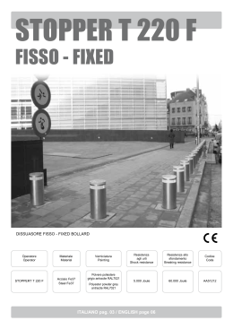
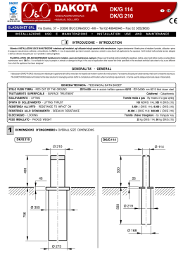
STOPPER T 275 F
FISSO - FIXED
DISSUASORE FISSO - FIXED BOLLARD
Operatore
Operator
Materiale
Material
Verniciatura
Painting
Resistenza
agli urti
Shock resistance
Resistenza
allo sfondamento
Breaking resistance
Codice
Code
STOPPERT T 275 F
Acciaio Fe37
Steel Fe37
Polvere poliestere grigio
antracite RAL7021
Polyester powder grey
antracite RAL7021
9.000 Joule
120.000 Joule
AA51215
ITALIANO pag. 03 / ENGLISH page 06
I
AVVERTENZE PER L’INSTALLATORE
OBBLIGHI GENERALI PER LA
SICUREZZA
G
B
WARNINGS FOR THE INSTALLER
GENERAL SAFETY OBLIGATIONS
1 -ATTENZIONE! E’ importante per la sicurezza delle persone seguire
attentamente tutta l’istruzione. Una errata istallazione o un errato
uso del prodotto può portare a gravi danni alle persone.
1 -ATTENTION! It is very important for the safety of people to follow
all instructions strictly. A wrong installation or use of the product
could cause serious damage to people.
2 -Leggere attentamente questo libretto d’istruzioni prima di iniziare
l’installazione del prodotto e conservarlo per riferimenti futuri.
2 -Read carefully this manual before starting installation and save it
for future reference.
3 -I materiali dell’imballaggio (plastica, polistirolo, ecc.) non devono
essere lasciati alla portata dei bambini in quanto potenziali fonti di
pericolo.
3 -Packaging materials (i.e. plastic, polystyrene, etc.) must be out of
children’s reach, because potentially dangerous.
4 -This product has been designed and manufactured exclusively on the
purpose indicated in this manual. Any different use not here indicated
could damage the integrity of the product and/or be potentially
dangerous.
4 -Questo prodotto è stato progettato e costruito esclusivamente per
l’utilizzo indicato in questa documentazione. Qualsiasi altro utilizzo
non espressamente indicato potrebbe pregiudicare l’integrità del
prodotto e/o rappresentare fonte di pericolo.
5 -RIB is not responsible for any damage caused by improper or different
use from the indicated one.
5 -RIB declina qualsiasi responsabilità derivata dall’uso improprio o
diverso da quello per cui il dissuasore è destinato.
6 -RIB is not responsible if someone does not observes the correct
method of installation of the STOPPER T products and related
devices, included deformations coming during the use.
6 -RIB non è responsabile dell’inosservanza della buona tecnica nella
installazione dei prodotti e dei relativi accessori, nonché delle
deformazioni che dovessero intervenire nell’utilizzo.
7 -For maintenance works use only original parts supplied by RIB.
7 -Per la manutenzione utilizzare esclusivamente parti originali RIB.
8 -The User must avoid any repairing actions or direct operations on the
bollard, and must address to qualified and authorized personnel only.
8 -L’utente utilizzatore deve astenersi da qualsiasi tentativo di riparazione
o d’intervento diretto e rivolgersi solo a personale qualificato ed
autorizzato.
9 -The product is packaged on Euro pallet; use pallets’ movers or
shunters for movement; handle with care.
9 -Il dissuasore è imballato su europallet; per la movimentazione
utilizzare trasportatori di pallet o muletti a norme e ponendo la
massima attenzione alla movimentazione.
10 -The product does not require availability of spare parts; RIB’ s
warehouse can send by express any needed spare parts.
10 -Il dissuasore non richiede la disponibilità di parti di ricambio; il
magazzino della RIB è organizzato per l’invio celere di qualsiasi
ricambio che dovesse essere richiesto.
11 -Everything not mentioned in this manual is not allowed.
11 -Tutto quello che non è previsto espressamente in queste
istruzioni non è permesso.
2
I
INSTALLAZIONE STOPPER T 275 F
STOPPER T 275 FISSO - ACCIAIO 6 mm
CARATTERISTICHE TECNICHE
Cilindro fisso
Trattamento cilindro fisso
Acciaio FE37 - spessore 6 mm
Vernice polvere poliestere antracite metallizzato RAL 7021.
Opzional: verniciatura personalizzata a spruzzo nella scala dei RAL
Diametro cilindro fisso
275 mm
Altezza cilindro fisso
600 mm
Parte superiore cilindro (testa)
Trattamento parte superiore cilindro
Alluminio anticorodal cementato
Vernice polvere poliestere colore grigio chiaro RAL 9006
Fascia adesiva rifrangente
Standard altezza 56 mm
Peso complessivo con zanche
kg 41
Resistenza urti senza deformazione
9.000 joule
Resistenza allo sfondamento
120.000 joule
SCHEMA DI POSA MURARIA
1 -Effettuare uno scavo manualmente o con mini-scavatore 0,30 m circa; la sezione, deve avere un lato di 1 m circa (come da schema di posa
allegato).
2 -Posare il controtelaio con le zanche di fondazione correttamente posizionate, avendo cura di posizionarlo a piombo, tenendo conto che il livello
superiore del controtelaio stesso deve essere più alto di circa 10 mm rispetto alla quota di calpestio (per limitare l’ingresso di acqua piovana).
Posizionare il controtelaio controllando il riferimento in relazione al senso di transito (vedere disegno allegato).
3 -Immettere calcestruzzo tutt’intorno al controtelaio, fino a - 5 cm circa dalla quota di calpestio (in caso di manto stradale in porfido, pietra o simile
valutare lo spessore opportuno); a calcestruzzo maturo eseguire la finitura del manto stradale con lo stesso tipo di materiale.
SCHEMA DI POSA IN CONTROTELAIO
Ad opere murarie concluse, effettuare il posizionamento del dissuasore fisso STOPPER T 275 con la seguente procedura.
1 -Posizionare il dissuasore fisso sul controtelaio e fissarlo con le viti in dotazione (10 viti a brugola M12 - chiave misura 10).
2 -Posizionare la corona di copertura con relativa gomma perimetrale del dissuasore e fissarla con le viti in dotazione (6 viti a brugola M6 - chiave
misura 5).
3
1
QUOTA DI CALPESTIO
4
Misure in mm
LIVELLARE
ZANCHE DI FONDAZIONE
2
MANTO STRADALE
QUOTA DI CALPESTIO
LIVELLARE
CONTROTELAIO
CALCESTRUZZO
SCHEMA DI POSA
3
I
SENSO DI TRAFFICO
PUNTO DI RIFERIMENTO
PER FISSAGGIO TELAI
ZANCHE DI FONDAZIONE
SCHEMA DI POSA MULTIPLA
I
5
G
B
STOPPER T 275 F INSTALLATION
STOPPER T 275 FIXED - FE 6 mm
TECHNICAL DATA
Fix cylinder
Steel FE 37 - thickness 6 mm
Fix cylinder treatment
Polyester powder painting - color anthracite RAL 7021.
Optional: personalized spray painting with RAL color
Fix cylinder diameter
275 mm
Fix cylinder height
600 mm
Upper part of the cylinder (head)
Upper part of the cylinder treatment
Anticorodal cemented alluminium
Polyester powder painting - color light grey RAL 9006
Adesive reflecting strip
Standard height 56 mm
Weight of the bollard with brackets
kg 41
Shock resistance
9.000 joule
Breaking resistance
120.000 joule
INSTALLATION SEQUENCE
1 -Dig a hole (using a miniature excavator or your hands) down to 0,30 m in depth approx. A sector side shall be 1 m circa approx. (see the picture
attached).
2 -Lay on the counterframe with the foundation clamps in correct position, paying attention that it has to be parallel to a plumb line and that the upper
level of the counterframe should be about 1 cm above the walking level (in order to reduce the flowing in of raining water). Further on, please pay
attention on the counterframe setting considering the traffic direction (see drawing enclosed).
3 -Introduce concrete all around about - 5 cm from the walking level (if the roadway it’s in porphyry, rock or similar value the right thickness); carry out
the finish work using the same material as the road course that is found all around the bollard.
cOUNTERFRAME INSTALLATION PLAN
To works building concluded, put STOPPER T 275 with the following procedure:
1 -Put the fixed bollard on the counterframe and fix it with the equipment screws (10 screws allen M12 - key measure 10).
2 -Put the cover crown with relative perimeter rubber of the bollard and fix it with the equipment screws (6 screws allen M6 - key measure 5).
6
1
TREAD LAVEL
7
Measurements in mm
2
TO LEVEL
FOUNDATION CLAMPS
TO LEVEL
COUNTERFRAME
CONCRETE
INSTALLATION PLAN
TREAD LAVEL
3
G
B
TRAFFIC WAY
REFERENCE FOR THE DIRECTION OF
THE COUNTERFRAME INSTALLATION
FOUNDATION CLAMPS
MULTIPLE INSTALLATION PLAN
G
B
8
9
NOTES
10
NOTES
11
Questo prodotto è stato completamente progettato e costruito in Italia · This product has been completely developed and built in Italy
25014 CASTENEDOLO (BS) - ITALY
Via Matteotti, 162
Tel. +39.030.2135811
Fax +39.030.21358279
www.ribind.it - [email protected]
Cod. CVA1809 - 25032009 - Rev. 00
Misure in mm / Measurements in mm
STOPPER T 275 F
Scaricare