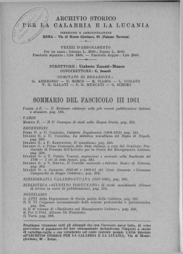
MANUALE USO E MANUTENZIONE
AEROEVAPORATORI A SOFFITTO
USE AND MAINTENANCE HANDBOOK
CEILING UNIT COOLERS
RS
RS REV. 08 04/10
I
UK
RS Pag. 2
REV. 08 04/10
ITALIANO
SOMMARIO
1. Scopo del manuale
2. Norme di uso generale
3. Modo di identificazione della macchina
4. Installazione
5. Collegamento frigorifero
6. Collegamento scarico condensa
7. Installazione elettrica
8. Dati tecnici
9. Manutenzione e pulizia
10. Smaltimento
11. Guasti - cause e rimedi
12. Optional
pag. 3
pag. 3
pag. 4
pag. 5
pag. 6
pag. 6
pag. 7
pag. 8
pag. 8
pag. 8
pag. 8
pag. 9
I
1.
SCOPO DEL MANUALE
Il presente manuale ha lo scopo di aiutare l’operatore nella corretta messa in funzione
dell’evaporatore, chiarire le relative norme di sicurezza vigenti nella comunità europea ed eliminare
eventuali rischi da errati utilizzi.
2.
NORME DI USO GENERALE
• Per un utilizzo corretto e sicuro della macchina, è necessario attenersi alle prescrizioni contenute
nel presente manuale in quanto fornisce istruzioni e indicazioni circa:
9 modalità di installazione
9 uso della macchina
9 manutenzione della macchina
9 smaltimento e messa fuori servizio
• Il costruttore non risponde per danni derivanti dalla inosservanza delle note e avvertenze contenute
nel presente libretto di istruzioni.
• Leggere attentamente le etichette sulla macchina, non coprirle per nessuna ragione e sostituirle
immediatamente in caso venissero danneggiate.
• Conservare con cura il presente manuale.
• Il costruttore si riserva di aggiornare il presente libretto senza nessun preavviso.
• Gli aeroevaporatori sono realizzati per la sola refrigerazione industriale e commerciale in sede
stabile. Non sono consentiti usi diversi da quello destinato. Ogni altro uso è considerato improprio
e quindi pericoloso.
• Dopo aver tolto l’imballo assicurarsi che la macchina sia intatta in ogni sua parte, in caso
contrario rivolgersi al rivenditore.
• E’ vietato l’utilizzo della macchina in ambienti con presenza di gas infiammabile e in ambienti con
rischio di esplosione.
• Non lavare la macchina con getti d’acqua diretti o in pressione, o con sostanze nocive.
• Non usare la macchina priva di protezioni (carenatura e griglia)
• Evitare che la macchina sia esposta a fonti di calore.
• In caso di incendio usare un estintore a polvere.
• Il materiale dell’imballaggio deve essere smaltito nei termini di legge.
3.
MODO DI IDENTIFICAZIONE DELLA MACCHINA
Tutte le macchine sono provviste di relativa etichetta di riconoscimento (la posizione è indicata in Fig.
1) in cui sono riportati i seguenti dati:
• sbrinamento:
• codice
n° di resistenze
• n° motoventilatori – n° giri (RPM)
assorbimento in Watt (W)
assorbimento in Watt (W)
tensione di alimentazione (Volt/Ph)
assorbimento in ampere (A)
• gruppo fluido refrigerante :Gruppo 2 (*)
tensione di alimentazione (Volt/Ph/Hz)
• pressione PS (pressione massima di lavoro)
• temperatura TS (temperatura minima di
esercizio)
• matricola
RS Pag. 3
REV. 08 04/10
(*) Secondo la normativa EN 378/1 appartengono al Gruppo 2 i seguenti gas :
R22,R134a,R507,R404A,R407C,R410A,R410B
Tutti gli evaporatori RS rientrano nella categoria 0 secondo la direttiva 97/23/CE (P.E.D.)
I
Fig. 1
120 min
B
P1
A
A
P2
P2
50
ETICHETTA
67
67
P3
119
119
42
26
26
A/2
A/2
40
Particolare Fissaggio
22
32
6
13
Modello
RS
Dimensioni
(mm)
Attacchi batteria
Attacco scarico
Peso
(Kg)
P1
P2
P3
A
B
entrata
scarico
vers.normale
vers.ED
4
1040 1040B 1060 1060B 2100 2100B 2130 2130B 3180* 3180B* 3290* 3290B* 4380* 4380B*
175
270
404
360
ø9,52
ø9,52
ø20mm
4,0
3,9
4,2
190
270
404
433
ø9,52
ø9,52
ø20mm
4,6
4,5
4,8
190
470
604
433
ø9,52
ø9,52
ø20mm
6,7
6,6
7,0
190
470
604
433
ø9,52
ø9,52
ø20mm
7,3
7,2
7,6
190
970
1104
433
1/2"SAE
16mm
ø20mm
10,5 10,4
11,0
190
970
1104
433
1/2"SAE
16mm
ø20mm
11,5 11,4
12,0
190
1245
622,5
1379
433
1/2"SAE
16mm
ø20mm
16,5 16,3
17,1
* Valvola termostatica con equilibrio esterno
Identificazione della matricola:
• cifra 1 e 2 = ultime due cifre dell’anno di costruzione
• cifra 3 e 4 = settimana dell’anno in cui è stata prodotta la macchina
• cifre 5,6,7e 8 = numero progressivo
4.
INSTALLAZIONE (Note generali)
L’installazione deve essere eseguita da personale qualificato, in possesso dei requisiti tecnici
necessari stabiliti dal paese dove viene installata la macchina.
Per la movimentazione della macchina, usare guanti di protezione antitaglio o sistema di
sollevamento idoneo.
Assicurarsi che la struttura su cui andrà fissato l’RS, sia adeguata al suo peso.
Non canalizzare l’aria dei motoventilatori per non aumentare le perdite di carico.
Condizioni particolari di funzionamento come celle troppo basse, stoccaggi eccessivi, ostacoli al getto
d’aria, possono influenzare le prestazioni dichiarate.
4. 1
Montaggio valvola termostatica (non fornita):
Dimensionare opportunamente la valvola termostaticha (N.B. - per i modelli RS3180-RS3180BRS3290-RS3290B-RS4380-RS4380B deve essere utilizzata una valvola termostatica con equilibrio
esterno e con l’uscita a flangiare).
Aprire la macchina come mostrato in Fig. 3, allentando le viti A e svitando le viti di fissaggio B.
RS Pag. 4
REV. 08 04/10
Sul tubo di ingresso dell’evaporatore, collegare l’uscita della valvola termostatica (Fig. 2 Part.A).
Solo per i modelli RS3180-RS3180B-RS3290-RS3290B-RS4380-RS4380B, predisporre il tubo
dell’equilibrio esterno che dovrà essere saldato sulla valvola termostatica e sul collettore
dell’evaporatore, nella posizione mostrata in Fig. 2 Part. B. Posizionare il bulbo della valvola
termostatica sul tubo di aspirazione, immediatamente prima del tubo dell’equilibrio esterno, se
presente (Fig. 2 Part.C) Fissare il bulbo sul tubo di aspirazione con delle fascette metalliche. Saldare
sull’ingresso della valvola termostatica, un tubo opportunamente piegato in precedenza (Fig. 2 Part
D). Il tubo uscirà dall’evaporatore attraverso il foro predisposto e sarà collegato successivamente alla
tubazione del liquido dell’impianto frigorifero.
Fig. 2
4. 2
Posizionamento a soffitto
Una volta fissata la valvola termostatica, fissare l’evaporatore al soffitto della cella.
La macchina deve essere installata solo in posizione orizzontale, utilizzando le apposite asole di
fissaggio. Gli interassi di fissaggio e la posizione delle ventole rispetto alle pareti della cella, è
mostrata in Fig. 1.
Lasciare intorno alla macchina sufficiente spazio per permettere un buon ricircolo dell’aria e per
effettuare le manutenzioni in condizioni di sicurezza. La distanza minima consigliata del lato motore
dalla parete, è di 120mm (Fig. 1).
Per il montaggio, aprire la macchina come mostrato in Fig. 3, allentando le viti A e svitando le viti di
fissaggio B.
Fissare la macchina utilizzando le 4 apposite asole sulla carenatura.
Per montare la resistenza di sbrinamento, posizionarla negli appositi scavi ricavati sopra la batteria e
fissarla con le due molle (G) fornite in dotazione.
Procedere con i collegamenti, frigorifero ed elettrico descritti nei paragrafi successivi.
Riposizionare il convogliatore e serrare le viti B ed A, come mostrato in Fig.3.
Collegare il tubo di scarico condensa al bocchettone F (fornito in dotazione).
5.
COLLEGAMENTO FRIGORIFERO
Collegare l’uscita dell’evaporatore sull’aspirazione dell’impianto frigorifero (è buona regola
realizzare un sifone).
Collegare il tubo che precedentemente era stato saldato all’ingresso della valvola termostatica, alla
tubazione del liquido dell’impianto frigorifero.
Per garantire una buona tenuta ermetica e ridurre i rischi di rottura, eseguire tutte le giunzioni tramite
saldatura a “bicchiere”. Se il diametro dei tubi non lo consente, utilizzare dei giunti a saldare idonei.
Durante le fasi di collegamento tubazioni, fare attenzione a non forzare o modificare la posizione del
collettore in quanto si potrebbero favorire rotture.
6.
COLLEGAMENTO SCARICO CONDENSA
La tubazione per lo scarico dell’acqua di condensa, và collegata all’attacco maschio da 1/2”Gas
situato al centro della vasca di raccolta (la pendenza minima deve essere superiore al 20%).
Predisporre sulla parete della cella in prossimità dell’evaporatore, un foro attraverso il quale la
tubazione uscirà per arrivare in un pozzetto a sifone. Sigillare il foro con silicone (di caratteristiche
idonee all’uso della cella) onde evitare infiltrazioni di aria calda. In caso di cella a temperatura
RS Pag. 5
REV. 08 04/10
I
negativa, la linea di scarico deve essere riscaldata durante il periodo di sbrinamento, con una
resistenza al silicone (optional) da circa 100W posta al suo interno.
Fig. 3
I
Carenatura
Batteria
A
Convogliatore
A
G
G
Resistenza di
sbrinamento solo
su modelli BED
Controgocciolatoio (*)
B
C
F
E
B
C
E
(*) Nota: solo per modelli RS….B e RS….BED
7.
INSTALLAZIONE ELETTRICA
Le operazioni di collegamento elettrico, devono essere eseguite da personale qualificato in possesso
dei requisiti tecnici necessari stabiliti dal paese dove viene installata la macchina
• Predisporre opportuni sistemi di protezione sulla linea di alimentazione ed accertarsi che la
tensione corrisponda a quella indicata sull’etichetta applicata sulla macchina (tolleranza
consentita ± 10% della tensione nominale).
• E’ obbligatorio, a termini di legge, collegare la macchina ad un efficiente impianto di messa a
terra. Si declina ogni responsabilità dall’inosservanza di tale disposizione e qualora l’impianto
elettrico a cui ci si allaccia non sia realizzato secondo le norme vigenti.
• Sugli evaporatori dotati di resistenze di sbrinamento, va installato un termostato meccanico tarato
a 40°C che disabilita le resistenze in caso di sovratemperatura. Il bulbo del termostato va
posizionato nel pacco alettato nel punto più alto dell’evaporatore.
7. 1
Collegamento elettrico
Collegare i motori e la resistenza all’alimentazione, utilizzando per il passaggio dei cavi, i prefori
laterali già predisposti.
Solo nel modello con codice RS….BED, di bassa con resistenze montate di serie, la resistenza ed i
motori sono già collegati su di una scatola di derivazione, secondo lo schema elettrico di Fig.4.
Tutti i modelli hanno motoventilatori alimentati con una tensione 220-240V/1Ph/50-60Hz, sui
modelli ED sono presenti le resistenze di sbrinamento alimentate 230V/1Ph/50-60Hz (vedi Fig. 4).
RS Pag. 6
REV. 08 04/10
Fig. 4
R
M
M
M
M
I
M = motoventilatori
R = Resistenza di sbrinamento
L2
L1
230V/1Ph/50-60Hz
220-240V/1Ph/50-60Hz
N1
Modello
Motoventilatori
Assorbimento motoventilatori
Assorbimento resistenze*
RS
RS…B
nxømm
A
W
W
N2
1040 - 1060
2100 - 2130
3180 - 3290
4380
1x200
0.25
43
400
2x200
0.50
86
600 - 650
3x200
0.75
129
1000
4x200
1
172
1300
* Le resistenze sono fornite montate e cablate, solo nei modelli RS….BED
I motori sono dotati di un sistema di protezione interna a riarmo automatico.
Se si intende utilizzare un sistema di regolazione del numero di giri del motoventilatore,
accertarsi che sia compatibile con il motoventilatore stesso.
8.
DATI TECNICI
Gli aeroevaporatori RS sono equipaggiati con motoventilatori assiali non adatti per prevalenze
aggiuntive.
Lo scambiatore di calore è in rame-alluminio, quindi non adatto ad essere impiegato in ambienti
aggressivi.
9.
MANUTENZIONE E PULIZIA
La manutenzione e pulizia devono essere eseguite solamente da tecnici specializzati.
Prima di qualsiasi operazione si deve verificare che la corrente elettrica sia disconnessa.
• Controllare il serraggio di tutti i morsetti all'interno della scatola di derivazione ( frequenza
quadrimestrale)
• Controllare visivamente tutto il circuito frigorifero, anche internamente alle macchine, alla ricerca
di perdite di refrigerante, che sono denunciate anche da tracce di olio lubrificante. Intervenire
tempestivamente e approfondire in caso di dubbio. (frequenza quadrimestrale)
• Pulire periodicamente l’evaporatore per evitare l’accumulo di sostanze nocive . Si consiglia l’uso
di acqua e sapone, evitando solventi, agenti aggressivi, abrasivi o a base di ammoniaca.
• In caso di sostituzione di componenti della macchina essi devono essere sostituiti con componenti
identici agli originali
Importante: al termine della manutenzione, riposizionare tutte le protezioni rimosse (carenatura e
griglia).
10.
SMALTIMENTO
Qualora la macchina sia messa fuori servizio, è necessario scollegarla dall’impianto elettrico. Il gas
contenuto all’interno dell’impianto non deve essere disperso nell’ambiente.
RS Pag. 7
REV. 08 04/10
11.
I
GUASTI Cause – rimendi
Problema
Evaporatore
ghiacciato
Evaporatore
ghiacciato solo
vicino alla
valvola
termostatica
Evaporatore
danneggiato
Ventilatori
bloccati
12.
Causa possibile
Durata fase sbrinamento troppo breve.
Intervallo tra due sbrinamenti troppo
lunghi.
Tempo di sgocciolamento insufficiente.
Infiltrazione dell’aria attraverso la porta,
aperta troppo frequentemente.
Resistenze elettriche bruciate.
L’afflusso del refrigerante all’evaporatore
è ridotto.
Orifizio della valvola termostatica troppo
piccolo.
Surriscaldamento elevato.
Rimedio
Aumentare il tempo di sbrinamento.
Aumentare i cicli di sbrinamento.
Verificare eventuali tubi schiacciati.
Verificare il tempo di sgocciolamento
impostato.
Ridurre la frequenza di apertura ed
eliminare eventuali fessure
Sostituire le resistenze guaste.
Controllare dimensionamento valvola
termostatica
Aumentare il diametro dell’orifizio.
Alette deformate.
Controllare le temperature ed agire sulla
valvola.
Raddrizzare le alette con un pettine.
Motore ventilatore guasto.
Tensione di linea inferiore ai limiti di
tolleranza.
Sostituzione.
Verificare il valore della tensione con un
voltmetro.
OPTIONAL
Batteria verniciata con vernice a polvere epossidica
La verniciatura della batteria, protegge la stessa dagli agenti corrosivi che possono essere presenti
nella cella.
Resistenze sbrinamento
In tutti i modelli, tranne nei modelli RS….BED (dove la resistenza è già montata e collegata in scatola di
derivazione), la resistenza di sbrinamento viene fornita su richiesta (a corredo)
Resistenza per il tubo di scarico
Si utilizza quando la cella dove è installato l’aeroevaporatore, lavora a temperatura negativa.
Deve essere inserita all’interno del tubo di scarico dell’acqua di condensa, in modo che l’acqua
formatasi durante lo sbrinamento, non congeli all’interno dello scarico.
RS Pag. 8
REV. 08 04/10
ENGLISH
Contents
1. Handbook purpose
2. Norms for general use
3. Machine identification
4. Installation
5. Refigerating connection
6. Condensate discharge connection
7. Electrics installation
8. Technical data
9. Maintenance and cleaning
10. Disposal
11. Failures and solutions
12. Optional items
pag. 10
pag. 10
pag. 11
pag. 12
pag. 13
pag. 13
pag. 14
pag. 15
pag. 15
pag. 15
pag. 15
pag. 16
UK
1.
HANDBOOK PURPOSE
This handbook is issued in order to assist an operator properly to bring the unit cooler on stream ,
give explainations about the relevant safety norms in force within the European Community and avoid
any risks that may be caused by a wrong usage.
2.
NORMS FOR GENERAL USE
• For a correct and safe use of the machine, it is necessary to follow the prescriptions present in this
manual as it gives instructions and information about :
9 installation
9 use
9 maintenance
9 disabling and disposal
• The manufacturer cannot accept any liability for damages resulting from failure to follow the
prescriptions and advice given in this handbook.
• Read carefully labels placed on the machine, do not cover them for any reason and replace them
in case they are damaged .
• Keep this manual carefully.
• The manufacturer may review this manual at any time, without notice.
• The unit coolers are designed for the use in industrial and commercial refrigeration application for
stable cold rooms. They are not intended for any other purpose. Any other use is to be considered
improper and dangerous .
• When the package is removed, please check that every part of the machine is intact; if not, contact
the retailer immediately .
• It is forbidden the use of the machine in environment with presence of inflammable gas or where
there is a risk of explosion.
• Do not clean the machine with direct water jet, under pressure or with improper substances .
• Do not use the machine without its protections ( housing and grid)
• Do not expose the machine to heating sources
• In case of fire use a powder fire extinguisher
• Packaging material must be suitably disposed of according to the low in force
3.
MACHINE IDENTIFICATION
All the machines are equipped with an identifying label (the position of the label is shawn in Drawing
1) where the following data are quoted :
Watt absorption(W)
• code
power supply voltage (Volt/Ph)
• no. of fan motors - no. of revolutions(RPM)
• refrigerant group: Group 2(*)
Watt absorption (W)
• PS pressure (max working pressure)
Ampere absorption (A)
Power supply voltage (Volt/Ph/Hz)
• TS temperature (min. operating temp.)
• defrosting:
• serial number
heaters number
(*) According to EN378/1 norm belong to the group 2 the following gas types:
RS Pag. 9
REV. 08 04/10
R22,R134a,R507,R404A,R407C,R410A,R410B
All RS range unit coolors belongs to CAT 0 in conformity with the 97/23/CE (P.E.D.) directive.
Drawing 1
120 min
B
UK
P1
50
A
A
P2
P2
Identifying label
ETICHETTA
67
67
P3
119
119
42
26
26
40
A/2
A/2
Fastening detail
22
32
6
13
Model
RS
Dimensions
(mm)
Coil connections
Drain connection
Weight
(Kg)
P1
P2
P3
A
B
inlet
outlet
Without ED
With ED
4
1040 1040B 1060 1060B 2100 2100B 2130 2130B 3180* 3180B* 3290* 3290B* 4380* 4380B*
175
270
404
360
ø9,52
ø9,52
ø20mm
4,0
3,9
4,2
190
270
404
433
ø9,52
ø9,52
ø20mm
4,6
4,5
4,8
190
470
604
433
ø9,52
ø9,52
ø20mm
6,7
6,6
7,0
190
470
604
433
ø9,52
ø9,52
ø20mm
7,3
7,2
7,6
190
970
1104
433
1/2"SAE
16mm
ø20mm
10,5 10,4
11,0
190
970
1104
433
1/2"SAE
16mm
ø20mm
11,5 11,4
12,0
190
1245
622,5
1379
433
1/2"SAE
16mm
ø20mm
16,5 16,3
17,1
*Thermostatic valve with external equaliser;
Serial number designation :
• number 1 and 2 = last two numbers of the manufacturing year
• number 3 and 4 = week of the year when the unit was manufactured
• numbers 5,6,7and 8 = progressive number
4.
4. 1
INSTALLATION (general notes)
Installation must be carried out by qualified personnel having the necessary technical requirements
asked for by the country where the machine is to be installed.
For moving the machine use safety anti-cut gloves and suitable hoisting device.
Check that the structure where the RS is going to be fixed is suitable to its weight .
Do not convey the motor fan air in order not to increase load losses.
Particular operating conditions such as cold rooms having too small height, excessive loading ,
obstacles to the air flow, may have an influence to the stated performances .
Thermostatic valve mounting (not supplied)
The thermostatic valve is to be properly sized (NOTE: for models RS3180-RS3180B-RS3290-RS3290BRS4380-RS4380B it is necessary to use a thermostatic valve with external equaliser and outlet to be
RS Pag. 10
REV. 08 04/10
flanged).
Open the machine, as illustrated in Drawing 3, loosening the screws A and unscrewing the fastening
screws B. Connect the thermostatic valve outlet to the evaporator inlet pipe (Drawing 2, point A).
For models RS3180-RS3180B-RS3290-RS3290B-RS4380-RS4380B only: fit the external equaliser
pipe, which must be welded to the thermostatic valve and to the evaporator manifold, in the position
shown in Drawing 2, point B. Place the thermostatic valve bulb on the suction pipe, just before the
external equaliser pipe, if fitted (Drawing 2 point. C). Fix the bulb on the suction pipe by means of
metal clamps.
Solder on the inlet side of the thermostatic valve, a pipe , previously bent in the proper way, (see
Drawing 2 ; Part D). The pipe will come out from the cooler through the preset hole and will be
connected then to the liquid pipe of the refrigerating system.
Drawing 2
4. 2
Positioning on the ceiling
Once the thermostatic valve is connected, fix the unit cooler to the cold room ceiling.
The unit has to be installed in horizontal position, only by means of the proper fixing slots. The fixing
distances between centers and the position of the fans relating to the cold room walls is shown in
Drawing 1. Keep around the unit enough space for a good air cycling and for a maintenance
operation in safe conditions. The minimum recommended distance from the wall for the motor side is
120 mm (Drawing 1). To assemble, open the machine, as illustrated in Drawing 3, loosening the
screws A and unscrewing the fastening screws B. Fix the machine, using the 4 special slots in the
casing. To fit the defrosting heater, place it in the relevant notches above the coil and fix it into place
using the two springs (G) (supplied).
Proceed to make the refrigerating and electrical connections, as described in the following
paragraphs.
Reposition the conveyor and tighten the screws B and A, as shown in Drawing 3.
Connect the condensation discharge pipe to the pipe union F (supplied).
5.
REFRIGERATING CONNECTION
Connect the evaporator outlet to the refrigerating system suction-pipe (we recommend fitting a
siphon).
Connect the pipe that was previously soldered to the inlet side of the thermostatic valve to the liquid
piping of the refrigerating system.
In order to guarantee a good hermetic seal and reduce break risks, execute all the joints by means of
a “ bell type” welding . If the pipe diameter do not allow that , use proper soldering joints .
During the pipe connection procedure pay attention not to force or modify the position of the header
as this may a cause of breaks.
CONDENSATE DRAIN CONNECTION
The piping for the condensate water drain is to be connected to the 1/2” Gas male connection placed
at the centre of the drip tray (the minimum gradient must be over 20%) . Provide on the cold room
wall, next to the unit cooler, for a hole through which the pipe will come out leading to a siphon trap.
Seal the hole by means of silicon (the features of which will be suitable to the cold room use) in order
to avoid infiltration of warm air. In case of a low temperature cold room the draining line must to be
6.
RS Pag. 11
REV. 08 04/10
UK
heated during defrosting time by means of a silicon heater (optional) of about 100W placed inside it .
Drawing 3
UK
Coil
Casing
A
A
G
Conveyor
G
Defrosting
heaters only
for BED
model
Drip tray (*)
B
C
F
E
B
C
E
(*) Note: Only for RS….B and RS….BED models
7.
ELECTRICAL INSTALLATION
The wiring must be carried out by qualified personnel having the necessary technical requirements
asked for by the country where the machine is to be installed.
• Provide for proper protection systems on the power supply line and check that the voltage
corresponds to that quoted on the label placed on the unit ( allowed tolerance ± 10% of the
rated tension).
• The law requires that the unit is earthed: therefore it is necessary to connect it to an efficient
earthing equipment. No liability whatsoever can be accepted if the above instruction requirement
is not complied with or if the electrical plant to which the unit is to be connected is not made by
following the law in force.
• For evaporators equipped with defrosting heaters, it is necessary to install a mechanical thermostat
(set to 40°C), which will disable the heaters in the event of excess temperature. The thermostat
bulb should be positioned in the fin coil, in the highest point of the evaporator.
RS Pag. 12
REV. 08 04/10
7. 1
Electrical connection
Connect the motors and the heater to the power supply, using the cable ducts already partially made
in the sides. For the model with the model code RS….BED (low temperature) only, with heaters fitted as
standard, the heater and motors are already connected to a terminal board, as illustrated in the
wiring diagram in Drawing 4. All models have fan motors that are powered at 220-240V/1Ph/5060Hz; ED models are equipped with defrosting heaters that are powered at 230V/1Ph/50-60Hz (see
Drawing 4);
UK
Drawing 4
R
M
M
M
M
M = Fan motors
R = Defrosting heater
L2
L1
230V/1Ph/50-60Hz
220-240V/1Ph/50-60Hz
N1
Model
Fan motors
Fan motor absorption
Heater power*
RS
RS…B
nxømm
A
W
W
N2
1040 - 1060
2100 - 2130
3180 - 3290
4380
1x200
0.25
43
400
2x200
0.50
86
600 - 650
3x200
0.75
129
1000
4x200
1
172
1300
*Heaters are supplied already fitted and wired on RS….BED models only.
The fan motors are equipped with an internal protection system with automatic cutout.
In case there is the need of fitting a regulation system of fan motor number of revolutions , check that
it is suitable for the fan motor itself .
8.
TECHNICAL DATA
RS unit coolers are equipped with axial fan motors which are not suitable for additional air pressure
drops
The heat exchanger is made of copper-aluminium; therefore it is not suited for being used in
aggressive ambient.
9.
MAINTENANCE AND CLEANING
Maintenance and cleaning have to be carried out by qualified technical presonnel only .
Before any intervention make sure that the electrical feed is disconnected from the mains.
• Check the fastening of all terminals inside the terminal box (every four months)
• Visually check the refrigerating circuit completely, also inside the machines, in order to detect
refrigerant leaks, that are also put in evidence by traces of lubricant oil. Make a fast intervention
RS Pag. 13
REV. 08 04/10
and further check in case of doubt . (every four month)
• Periodically clean the unit in order to avoid deposits of toxic substances. The use of water and
soap is recommended and avoid using solvents , aggressive agents , abrasive or ammonia-based
materials.
• In the event that machine parts need replacing, they have to be replaced by items exactly the
same to the originals ones
Important: once the maintenance is accomplished, replace all safeties previously removed (housing
and grid ).
UK
10.
DISPOSAL
In case the machine is to be disabled , it is necessary to disconnect it from the mains. The gas inside
the plant must not be dispersed in the environment.
11.
FAILURES : Causes – solutions
Problem
Possibile cause
Defrosting time too short
Time Interval between two defrostings too
long
Iced Evaporator
Dripping time not long enough
Air infiltration through the door which is
too frequently opened
Burnt electrical heaters.
The refrigerant inflow to the evaporator is
Iced evaporator reduced .
only near the
The orifice of the thermostatic valve is too
thermostatic
little.
valve
High Overheating.
Damaged
evaporator
Blocked fan
motors
12.
solution
Increase defrosting time.
Increase defrosting cycles.
Check the possibile presence of
squashed pipes
Check the set dripping time.
Reduce the door opening frequency
and eliminate possibile fissure
Replace the faulty heaters .
Check the size of the thermostatic
valve.
Increase the orifice diameter
Deformed finns
Check the temperatures and operate
on the valve
Straighten the finns with a comb .
Fan motor breakdown.
Mains Tension lower than the allowed
limits.
Replacement.
Check the tension value by a voltmeter
.
OPTIONAL ITEMS
Coil painted with epoxy powder varnish
The varnishment gives the coil a protection from corrosive agent that can be present inside the cold
room.
Defrosting heater
All RS models , except for RS...BED ones ( where the heater is already fitted and wired in a terminal
box) the defrosting heater is being supplied not fitted and only upon specific request .
Discharge pipe heater
This is used when the cold room where the unit cooler is installed operates at a negative temperature.
It has to be inserted inside the condensation water drain pipe so that the water formed during
defrosting does not freeze inside the drain pipe.
RS Pag. 14
REV. 08 04/10
COD. 99215002
S.r.l. - Costruzione Gruppi Frigoriferi e Accessori
Via Sicilia, 7 - 61020 Montecchio (PU) - Italy - Tel. +39 0721 919911- Fax +39 0721 490015
www.rivacold.com - [email protected]
Scaricare