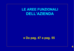
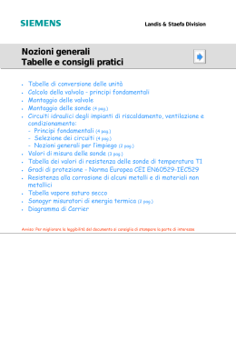
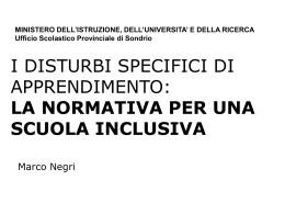
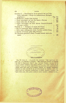
LIBRETTO
LIBRETTO USO
USO EE MANUTENZIONE
MANUTENZIONE
USE
USE AND
AND MAINTENANCE
MAINTENANCE MANUAL
MANUAL
MESCOLATORE
MESCOLATORE SOTTOVUOTO
SOTTOVUOTO
VACUUM
VACUUM MIXER
MIXER
DAKO
DAKO 5400
5400
DAKO 5400
Indice / Index
ITALIANO
IDENTIFICAZIONE DEL COSTRUTTORE ....................................................................................................................................... pag.3
INFORMAZIONI TECNICHE ............................................................................................................................................................. pag.3
DISPOSITIVI DI SICUREZZA ........................................................................................................................................................... pag.3
DATI TECNICI ................................................................................................................................................................................... pag.3
MOVIMENTAZIONE ED INSTALLAZIONE ....................................................................................................................................... pag.4
Imballo e disimballo .......................................................................................................................................................................... pag.4
Carico e scarico ................................................................................................................................................................................ pag.4
Modalità di installazione .................................................................................................................................................................... pag.4
DESCRIZIONE COMANDI ............................................................................................................................................................... pag.4
FUNZIONAMENTO ED USO ............................................................................................................................................................ pag.5
AVVERTENZE .................................................................................................................................................................................. pag.5
INFORMAZIONI PER LA MANUTENZIONE .................................................................................................................................... pag.5
Manutenzione ordinaria .................................................................................................................................................................... pag.5
Manutenzione straordinaria .............................................................................................................................................................. pag.5
Precauzioni ....................................................................................................................................................................................... pag.5
GARANZIA ........................................................................................................................................................................................ pag.5
Certificato di Garanzia su modello UNIDI-ANCAD ........................................................................................................................... pag.5
Regolamento ..................................................................................................................................................................................... pag.6
ENGLISH
IDENTIFICATION OF THE MACHINE MANUFACTURER ............................................................................................................... pag.7
TECHNICAL INFORMATION ............................................................................................................................................................ pag.7
SAFETY DEVICES ........................................................................................................................................................................... pag.7
TECHNICAL DATA ............................................................................................................................................................................ pag.7
MOVING AND INSTALLING ............................................................................................................................................................. pag.8
Packaging and unpackaging ............................................................................................................................................................. pag.8
Loading and unloading ...................................................................................................................................................................... pag.8
CONTROL DEVICES DESCRIPTION .............................................................................................................................................. pag.8
FUNCTION AND USE INSTRUCTIONS ........................................................................................................................................... pag.9
GENERAL INSTRUCTIONS ............................................................................................................................................................. pag.9
MAINTENANCE INFORMATION ...................................................................................................................................................... pag.9
Ordinary maintenance ....................................................................................................................................................................... pag.9
Extraordinary maintenance ............................................................................................................................................................... pag.9
Precautions ....................................................................................................................................................................................... pag.9
WARRANTY ...................................................................................................................................................................................... pag.9
Certificate of garantee (approved by UNIDI) ..................................................................................................................................... pag.9
Garantee regulations ........................................................................................................................................................................ pag.10
SCHEMA ELETTRICO / ELECTRIC PLANT. ................................................................................................................. pag.11
RICAMBI / SPARE PARTS. ................................................................................................................................................... pag.12
DICHIARAZIONE DI CONFORMITÁ / DECLARATION OF CONFORMITY. ..................................................... pag.15
The Manufacturer reserves the right to modify the technical and functional features of the appliances described in this instruction manual without giving prior notice;
also, will not answer for any inaccuracies, attributable to printing or transcription errors, in this instruction manual.
Il Costruttore si riserva il diritto di apportare modifiche alle caratteristiche tecniche e funzionali dei prodotti presentati in questa pubblicazione senza dare alcun preavviso;
inoltre, non risponde di possibili inesattezze, imputabili ad errori di stampa o di trascrizione, contenute nel presente libretto.
2
DAKO 5400
IDENTIFICAZIONE DEL COSTRUTTORE
Questo manuale é stato redatto dal Costruttore ed è
parte integrante del corredo della macchina.
Sulla macchina è posta la targhetta come da fig. 1.
sottostante.
Le informazioni in esso contenute sono rivolte
all’utilizzatore e contengono le indicazioni di sicurezza.
Prima di usare la macchina, in particolar modo la prima
volta, è bene leggere il manuale, al fine di prendere dimestichezza con i comandi, comprendere la loro funzione e la loro posizione.
È cosigliabile, inoltre, effettuare delle prove d’uso.
Il manuale deve essere conservato per futuri riferimenti.
SARATOGA
SpA
PORDENONE - ITALY
MODEL
SERIAL N°
DATA
VOLT
Hz
KW
INFORMAZIONI TECNICHE
DISPOSITIVI DI SICUREZZA
Il mescolatore DAKO 5400 è stato progettato e costruito per la mescolazione di rivestimenti e gessi in laboratori odontotecnici ed in conformità ai requisiti di sicurezza (fig.2).
F-Riparo fisso: impedisce l’accesso alle parti elettroniche
G-riparo fisso: impedisce l’accesso alle parti meccaniche
DATI TECNICI
D
Dimensioni (ingombro max): 30x61x42 (LxHxP)
Peso:
35Kg
Tensione all’alimentazione: 220V
Frequenza:
50Hz AC
Potenza:
500W
Velocità di spatolazione:
200g/min
Capacità tazza standard:
650cc
Vuoto max raggiungibile:
720mmHg
Fusibili:
5A
F
A
B
G
C
E
A) Telaio
B) Tubo di aspirazione
C) Cavo 220V 50Hz
D) Pannello dei comandi
E) Gruppo tazze
F) Riparo fisso
G) Riparo fisso
3
ITALIANO
DAKO 5400
DAKO 5400
Carico e scarico
MOVIMENTAZIONE ED INSTALLAZIONE
Durante la movimentazione evitare assolutamente di
sottoporre la macchina ad urti, cadute o ribaltamenti:
ciò potrebbe danneggiarla in modo anche irreparabile.
Ovviamente il costruttore non risponde di danni provocati da cadute, cattivo uso o inosservanza delle norme
di uso e manutenzione enunciate nel seguente libretto.
Imballo e disimballo
L'imballo è formato da (fig.3):
A - Alloggiamento di polistirolo K10
B - Lastra di polistirolo
C - Scatola in cartone duro
A
Lo smaltimento dei materiali di imballo dev'essere effettuato nel rispetto dell'ambiente e delle norme vigenti.
Modalità di installazione
B
Collegare la spina di alimentazione ad una presa di
corrente 220V.
E' compito dell'utilizzatore accertarsi che l'impianto elettrico del locale sia costruito secondo le norme di sicurezza vigenti. In particolare verificare che la messa a
terra dell'impianto sia ben efficiente.
É importante, inoltre, verificare la tensione di rete: se la
tensione è troppo bassa (inferiore a 210V) il motore parte
troppo lentamente e quindi può essere necessario installare un gruppo di stabilizzazione.
C
5
6
DESCRIZIONE COMANDI
1
Interruttore generale: azionandolo si accende la
macchina e si illumina il display 7
Scarico a vuoto (pulsante rosso): prernendolo e tenendolo premuto si fa entrare l'aria nelle tazze e,
quindi, si elimina il vuoto.
Pompa (pulsante blu ON\OFF): si accende e si spegne la pompa per il vuoto.
Spia della pompa: quando è accesa indica che la
pompa è accesa.
2
3
4
5
4
6
7
8.
9.
10.
7
8
3
11.
2
9
18
10
19
12.
13.
14.
11
20
14
21
12
22
23
1
13
15
19.
20.
21.
16
17
4
15.
16.
17.
18.
22.
23.
Vuotometro
Vibratore: ruotando la manopola in senso orario si
mette in funzione il vibratore e, quindi, si regola la
vibrazione: la vibrazione è massima con la manopola tutta verso destra.
Display del timer: indica il tempo impostato per la durata
della spatolazione. Durante la spatolazione, il tempo decresce al trascorrere fino a 0.
Il tempo è espresso in secondi.
Pulsante STOP: premendolo si ha l'arresto istantaneo del ciclo di spatolazione.
Pulsante START: premendolo si dà inizio al ciclo di
spatolazione.
Tempo di spatolazione: ruotando questa manopola si
imposta il tempo di spatolazione: il tempo impostato viene visualizzato nel display 7.
Ruotando la manopola verso destra il tempo aumenta
fino ad un massimo di 250 sec., ruotandola verso sinistra il tempo decresce fino a 5 sec.
Rubinetto: dev'essere aperto all'installazione della
macchina e non dev'essere più richiuso.
Spatola.
Tazza superiore.
Rubinetto dosatore: si apre ruotandolo e ponendo
la leva in posizione verticale quando si effettua la
colata sottovuoto.
Tazza inferiore.
Basetta in gomma portacilindri.
Piano vibrante.
Giunto mobile: trasmette la rotazione dal motore
all'albero della spatola.
Innesto rapido: collega le tazze alla pompa del vuoto.
Coperchio tazze.
Fermo del rubinetto: svitandolo, si può estrarre il
rubinetto dosatore per pulirlo alla fine del ciclo.
Portafusibili.
Spina d'alimentazione 220V AC.
FUNZIONAMENTO ED USO
AVVERTENZE
1.
Si consiglia di preparare il rivestimento nelle sue giuste
dosi in una ciotola ed eseguire una breve prespatolazione manuale: questo per evitare di introdurre
nelle tazze polvere ed acqua tra loro separate, col rischio che la polvere venga aspirata dalla pompa del
vuoto e l'acqua si depositi sul fondo.
Evitare di mettere troppo rivestimento nella tazza superiore per non otturare i condotti del vuoto: stare a
non meno di 2 centimetri dal bordo superiore della tazza.
2.
3.
4.
5.
7.
8.
9.
10.
11.
12.
13.
14.
15.
16.
17.
18.
Accendere l'apparecchio tramite l'interruttore generale 1.
Togliere le tazze dalla macchina e disporre la basetta in gomma 16 con su il cilindro e il modello in
cera nella tazza inferiore 15.
Mettere nella tazza superiore 13 la quantità necessaria di rivestimento e di acqua (assicurandosi che
il rubinetto 14 sia chiuso, cioè con la leva in posizione orizontale).
Chiudere la tazza superiore con il coperchio 20.
Mettere la tazza superiore 13 sopra la tazza inferiore 15, facendole bene incastrare una nell'altra
6. Sollevare il giunto 18 e fermarlo nella sua posizione alta.
Posizionare il gruppo tazze sul piano di gomma 17
del vibratore centrandololo nell'apposito perno di
riferimento.
Far scendere il giunto mobile 18 e farlo incastrare
nel perno alla sommità delle tazze.
Agganciare il giunto 19 e chiudere la vicina valvola
manuale di scarico lento (ruotandola verso destra).
Impostare con la manopola 10 il tempo di
spatolazione: il tempo impostato verrà visualizzato
nel display 7.
Dare inizio alla spatolazione premendo il pulsante
9 (start).
Azionare la pompa per il vuoto tramite il pulsante 3
(pompa): la lancetta del vuotometro 5 raggiungerà
in pochi secondi valori prossimi a 70 mmHg. Se
ciò non avviene significa che le tazze non sono ben
posizionate.
ATTENZIONE! Alla prima accensione ricordarsi di
aprire il rubinetto 11.
Trascorso il tempo di spatolazione programmato, il
motore si ferma e si può, quindi, iniziare la fase di
colata, aprendo il rubinetto 14.
A questo punto, si consiglia di spegnere la pompa.
Durante la colata, si può migliorare la
compattazione del rivestimento dentro il cilindro,
azionando il vibratore mediante la manopola 6 e,
regolando, con la stessa manopola, I'intensità della vibrazione.
L'operazione di colata si può fare sottovuoto oppure a pressione atmosferica. In questo secondo
caso, si può eliminare il vuoto dalle tazze premendo e tenendolo premuto il pulsante 2 (scarico vuoto) oppure aprendo la valvola di scarico lento posta sul coperchio delle tazze.
Terminata la colata, spegnere il vibratore, eliminare il vuoto col pulsante 2 e togliere le tazze dalla
macchina sollevando il giunto 18 e disinnescare il
raccordo 19.
Dopo aver tolto le tazze dalla macchina e averle
separate, pulire accuratamente la spatola, il coperchio e la tazza superiore.
Se necessario, togliere il rubinetto 14 dalla sua sede
dopo aver svitato il pomello di fermo 21.
Prima di rimontare il rubinetto, lubrificare le guarnizioni con grasso al silicone.
Togliere la basetta con su il cilindro dalla tazza inferiore: essiccato il rivestimento, è pronto per essere messo in forno.
INFORMAZIONI PER LA MANUTENZIONE
Manutenzione ordinaria
Mantenere sempre pulite e lubrificate con grasso
siliconico tutte le guarnizioni della macchina e controllare che esse siano sempre in perfetto stato.
Non utilizzare solventi per la pulizia che vadano a deteriorare le guarnizioni
Manutenzione straordinaria
Per la riparazione o sostituzione delle parti, rivolgersi
esclusivamente a personale riparatore qualificato o direttamente alla casa costruttrice.
Evitare assolutamente di aprire i ripari fissi della macchina senza aver preso le necessarie precauzioni.
Prima di effettuare qualsiasi intervento di manutenzione straordinaria staccare la spina dalla
presa di corrente
Precauzioni
All'interno della macchina vi sono componenti soggetti
alla tensione di rete di 220V.
Prima di effettuare qualsiasi intervento all'interno della
macchina, spegnere l'interruttore generale 1 e staccare la spina 23 (le stesse precauzioni vanno prese anche per la sostituzione dei fusibili).
La mancata osservanza delle norme contenute nel presente libretto solleva il costruttore dai suoi impegni di
garanzia e responsabilità.
GARANZIA
Certificato di Garanzia su modello UNIDI-ANCAD
1. Col presente documento il fabbricante certifica la corretta costruzione del prodotto, l’impiego di materiali
di prima qualità, l’effettuazione di tutti i collaudi necessari e la sua aderenza alle norme vigenti. Il prodotto è coperto da un periodo di Garanzia di mesi
12 dalla data di consegna all’utente, che dovrà essere comprovata dalla restituzione dell’allegato tagliando controfirmato dall’Utente.
La garanzia è limitata alla sostituzione o sistema5
ITALIANO
DAKO 5400
DAKO 5400
zione delle singole parti o dei pezzi che risultano di
fabbricazione difettosa, con esclusione delle spese
di manodopera, trasferta del personale tecnico, spese di trasporto, di imballaggio, ecc.
Sono esclusi dalla Garanzia guasti o danni derivanti
da cattiva manutenzione, da scorretta alimentazione, negligenza, imperizia o cause non imputabili al
fabbricante.
Sono da escludersi dalla Garanzia le avarie causate da mancata manutenzione ordinaria dovuta a trascuratezza dell’utilizzatore.
La presente Garanzia non comporta alcun risarcimento di danni diretti o indiretti di qualsiasi natura
verso persone o cose, dovuti all’eventuale inefficienza dell’apparecchiatura.
2. La Garanzia decade automaticamente qualora le
apparecchiature vengano riparate, modificate o comunque manomesse dall’acquirente o da terzi non
autorizzati.
3. Per gli interventi in Garanzia l’acquirente dovrà rivolgersi
unicamente al venditore, oppure ai centri di assistenza
indicati dal fabbricante o al produttore stesso.
La Garanzia dà diritto alla sostituzione gratuita della
parte difettosa. É comunque escluso il diritto alla sostituzione dell’intero apparecchio.
4. Nel caso di contestazione sull’applicazione della Garanzia, sulla qualità o sulle condizioni delle
apparecchiature consegnate, l’acquirente non potrà
sospendere o ritardare il pagamento del prezzo o
delle rate di prezzo.
5. Nessun risarcimento potrà essere richiesto dall’acquirente per fermo delle apparecchiature.
6. La Garanzia decade se:
a) l’apparecchiatura presenta danneggiamenti provocati da caduta, da esposizioni a fiamme, da rovesciamenti di liquidi, da fulmini, da calamità naturali,
o comunque da cause non imputabili a difetti di fabbricazione;
b) non vi è stata una corretta installazione;
c) vi è stato collegamento alla rete (tensione nominale di alimentazione errata);
d) il numero di matricola risulti asportato, cancellato
o alterato.
7. I componenti da sostituirsi in garanzia, devono essere restituiti alla Casa che ha provveduto o provvederà alla spedizione del ricambio. Qualora il pezzo
cambiato non venga restituito, verrà addebitato all’ordinante.
8. Per ragioni fiscali le parti di ricambio verranno
concesse in garanzia unicamente nel caso in cui
ci sia pervenuto il tagliando di garanzia contenente tutti i dati relativi al cliente.
6
REGOLAMENTO
1. La mancata restituzione del Certificato di Garanzia
implica l’immediata decadenza della medesima.
La Garanzia non copre le spese di manodopera e
trasferta che saranno sempre e comunque a carico
dell’acquirente.
2. Il pagamento delle fatture di manodopera, trasferta
e diritto di chiamata, dovrà avvenire a presentazione delle medesime. Il mancato pagamento implicherà l’automatico decadimento della Garanzia.
3. Il fabbricante nonché il Deposito Dentale non sono
tenuti a dare in uso apparecchiature sostitutive per
il periodo di riparazione.
4. Per ogni altro caso non contemplato dal presente
Certificato di Garanzia e dal regolamento si fa riferimento alle norme del Codice Civile.
Legge 31 dicembre 1996, n. 675
I Clienti sono informati, ai sensi dell’art. 10 della Legge
31 dicembre 1996, n. 675, e pertanto approvano espressamente che i dati forniti per l’attivazione delle clausole
di garanzia possono essere trattati da SARATOGA
S.p.a., con sede legale in Pordenone, per:
a) l’adempimento degli obblighi previsti da leggi, regolamenti e dalla normativa comunitaria, ovvero da disposizioni impartite da autorità a ciò legittimate dalla legge, nonché da organi di vigilanza;
b) finalità strettamente connesse e strumentali all’esecuzione ed alla gestione del contratto con Lei/Voi
stipulato;
c) finalità gestionali, statistiche, commerciali, di
marketing e promozionali.
Il conferimento dei dati personali di cui alla lett. a) è
obbligatorio ed il rifiuto di fornirli determinerà l’impossibilità dell’instaurazione e/o della prosecuzione
del rapporto commerciale. Il conferimento dei dati
personali di cui alla lett. b) non è obbligatorio, ma il
rifiuto di fornirlo determinerà l’impossibilità
dell’instaurazione e/o della prosecuzione del contratto con Lei/Voi concluso, nonché delle operazioni
di revisione e riparazione relative alla fornitura alla
quale il contratto si riferisce. Il conferimento dei dati
di cui al punto c) non è obbligatorio, ma il rifiuto di
fornirli determinerà l’impossibilità per Lei/Voi di fruire di iniziative commerciali della Società, nonché di
essere destinatario di materiale promozionale della
medesima.
Il trattamento per le finalità di cui alle lett. a) e b) e c)
non richiede il consenso, ai sensi dell’art. 12, comma
1, lett. a) e b) L. 675/96.
DAKO 5400
DAKO 5400
IDENTIFICATION OF THE MACHINE
MANUFACTURER
This manual has been written by the manufacturer and
it is an integral part of the machine. Its information are
addressed to the user and contain all Safety
Recommendations.
On the machine you can find the label as shown in fig.1
below.
ENGLISH
Before using this mixer, it is recommended that you read
this manual carefully, especially if it is the first time, to
ensure you know the control devices, their function and
position. It is also advisable to make performance tests.
This manual must be kept for future references.
SARATOGA
SpA
PORDENONE - ITALY
MODEL
SERIAL N°
DATA
VOLT
Hz
KW
TECHNICAL INFORMATION
SAFETY DEVICES
The DAKO 5400 vacuum mixer has been planned and
built to mix coatings, casts and plasters in dental
laboratories in accordance with all Safety
Recommendations (fig. 2).
F-Fixed guard: to avoid access to the electronic parts.
G-Fixed guard: to avoid access to the mechanical parts.
TECHNICAL DATA
D
Overall dimensions:
Weight:
Voltage:
Frequency:
Output
Paddling speed:
Standard bowl capacity:
Maximum vacuum:
Fuse rating:
F
A
30x61x42 (LxHxP)
35Kg
220V
50Hz AC
500W
200g/min
650cc
720mmHg
5A
B
G
C
E
A-Frame
B-Aspirator piece
C-220V 50Hz electric cable
D-Control panel
E-Bowls group
F-Fixed guard
G-Fixed guard
7
DAKO 5400
Loading and unloading
MOVING AND INSTALLING
While moving the machine avoid absolutely any kind of
bumping, dropping or tilting they could seriously damage
the machine.
Packaging and unpackaging
The packaging is as follows:
A-Polystyrene housing K10
B-Polystyrene plate
C-Hard cardboard box
Obviously, the manufacturer is not responsable for
damages caused by droppings, improper use and
maintenance which are not in strict accordance with the
manufacturer’s instructions contained in this manual.
Packaging waste disposal must be done with respect
to the the environment and the law in force.
A
B
Installation instructions
Connect the power supply plug into a 220V AC outlet.
It is duty of the user to ensure that the electric plant is in
accordance with the safety laws in force.
It is particular important to make sure that grounding is
well efficient.
C
Furthermore, it is important to verify the network voltage:
in case the voltage is too low (lower than 210V), the
engine will start too slow and it might be necessary to
install a voltage stabilizer.
5
6
CONTROL DEVICES DESCRIPTION
1
General power switch: the machine turns on and
the display 7 lights up.
Vacuum exhaust (red button): by pressing and
keeping it pressed the air will go in the bowls and
therefore eliminates the vacuum.
Pump (ON/OFF blue button): turns on and off the
vacuum pump.
Pump warning light: it lights up when the pump is
on.
2
3
4
5
4
6
7
8
9
10
7
8
3
11
2
9
18
10
12
13
14
19
11
20
14
21
12
22
23
1
13
15
16
17
8
15
16
17
18
19
20
21
22
23
Vacuum gauge.
Vibrator: it turns on by rotating the knob clockwise.
Regulate the vibrator by rotating the knob (maximum
vibration is obtained by rotating the knob all the way
to the right).
Timer display: it indicates the set time for the
paddling cycle. During the paddling the time will
decrease up to 0. Time is indicated in seconds.
STOP pushbutton: by pushing, it the paddling cycle
will immediately come to a stop.
START pushbutton: by pushing it, you start the
paddling cycle.
Paddling time: by rotating this knob you will set the
paddling time and the display 7 will show it. By
rotating the knob to the right the time will increase
up to a maximum of 250 seconds whereas by
rotating it to the left the time will decrease up to 5
seconds.
Cock: it must be opened during the installation of
the machine and must never be closed.
Spattle.
Upper bowl.
Dosage cock: it opens by rotation. Set the lever at
vertical position for pouring in vacuum.
Lower bowl.
Rubber base cylinder sholder.
Vibrator plate.
Jointed coupling: it transmits the rotation from the
engine to the spattle spindle.
Fast clutch onnects the bowls to the vacuum pump.
Bowls lid.
Cock stop device: by loosening it, you can remove
the dosage cock in order to clean it after the cycle.
Fusesholder.
220V AC power supply plug.
FUNCTION AND USE INSTRUCTIONS
GENERAL INSTRUCTIONS
1
It is advisable to prepare the mixture of the coating with
the right dosage, in a separate container and perform a
manual quick pre-paddling: this is to avoid introducing
in the bowls powder and water fully separated with the
risk that the powder could be sucked out by the vacuum
pump and the water could deposit at the bottom.
Avoid placing too much coating in the upper bowl so
not block the vacuum pipes: stay 2 centimetres minimum
below the bowl upper edge.
2
3
4
5
6
7
8
9
10
11
12
13
14
15
16
17
18
Turn the machine on with the general power
switch 1.
Remove the bowls from the machine and place the
rubber base 16 with the cylinder and the wax
sample on the lower bowl 15.
Place in the upper bowl 13 the needed amount of
coating and water (make sure that the cock 14 is
closed, meaning with the lever at horizontal
position).
Close the upper bowl with the lid 20.
Place the upper bowl 13 on top of the lower bowl
15 making sure they are perfectly embedded one
in the other.
Lift the coupling 18 and leave it at its high position.
Place the bowls group on the rubber plate 17 of
the vibrator centering it in the special reference bolt.
Let the jointed coupling 18 go down and make it fit
on the bolt at the top of the bowls.
Hook up the the clutch 19 and close the nearby
slow exaust manual valve by rotating it to the right.
With the knob 10 set the paddling time: the display
7 will show the set time.
Start the paddling cycle with the pushbutton 9
(START).
Start the vacuum pump with the blue button 3
(pump): the vacuum gauge pointer 5 will reach in
few seconds values close to 70mmHg. If this doesn’t
happen it means that the bowls are not placed
properly.
WARNING!! When you first turn the machine on
remember to open the cock 11.
As the set paddling cycle time elapses the engine
will stop and therefore you can start the pouring
phase by opening the cock 14. At this point it is
advisable to turn off the pump.
During the pouring phase you can improve the
compactness of the coating inside the cylinder by
turning the vibrator with the knob 6 and regulating,
with the same knob, the intensity of the vibration.
The pouring of the coating in the cylinder can be
performed either in vacuum or atmospheric
pressure conditions. In the latter, you can eliminate the vacuum in the bowls by pressing and keeping
pressed button 2 (vacuum exaust) or by opening
the slow exaust valve located on the bowls lid.
Once the pouring is over turn off the vibrator, eliminate the vacuum with button 2 and remove the
bowls from the machine by lifting the coupling 18
and disconnecting the clutch 19.
After having removed the bowls from the machine
and having separated them, carefully clean the
spattle, the lid and the upper bowl. If necessary
remove the cock 14 from its site after having
loosened the cock stop device 21. Before
reinstalling the cock make sure to lubricate the
packings with silicone grease.
Remove the rubber base with the cylinder from the
lower bowl: once the coating is dry you can readily
put it in the kiln.
MAINTENANCE INFORMATION
Ordinary maintenance
All the packings of the machine must be kept well
cleaned and lubricated with silicone grease and checked
they are always in perfect conditions.
To clean the packings never use any solvents that could
damage them.
Extraordinary maintenance
To repair the machine or replace some of its parts, the
user should consult directly the manufacturer or only
specialized technicians.
Absolutely avoid to open any of fixed guards without
proper precautions.
Disconnect the power supply plug from the outlet before
any extraordinary maintenance operation.
Precautions
Inside the machine there are components subjects to
220V network voltage.
Before performing any operation inside the machine
make sure you turned off the general switch 1 and
unplugged the power supply 23 (same precautions must
be taken when substituting the fuses).
If the user doesn’t stricly follow the rules contained in
the manufacturer is lifted from any guarantee and
responsability.
WARRANTY
Certificate of garantee (approved by UNIDI)
1. Through the present document the manufacturer
certificates a correct construction of the product and
assures that first materials have been used; all
necessary approvals and trials have been made so
that the product is conform to the regulations in force.
The guarantee on this product is valid for a period of
12 months starting on the day of delivery to the
purchaser. The purchaser approves the guarantee
regulations by filling in and signing his part and
returning it to the manufacturer.
The guarantee only covers those parts to be
substituted or replaced because of construction faults
9
ENGLISH
DAKO 5400
DAKO 5400
and doesn’t cover labour expensens, travelling
indemnity of technicians, transport expenses,
packing etc.
The guarantee excludes damages or failures caused
through a bad maintenance, a wrong feeding supply,
negligences, unskillfulness or other causes not
imputable to the manufacturer.
The guarantee excludes as well failures caused
through ommissed maintenance due to the
negligences of the user.
The guarantee doesn’t include any kind of refund
versus persons or objects for damages, direct or
indirect, due to eventual inefficiency of the
equipment.
2. The guarantee forfeits automatically in case that the
equipment has been repaired, modified or tampered
by the purchaser himself or by unauthorized third
parties.
3. For interventions under guarantee, the purchaser
must address himself to the selling-agent, or the by
him indicated technical-service or direct to the
manufacturer. The guarantee gives the right to
substitution of the defective part, but excludes the
substitution of the entire equipment.
4. In case of contestation concerning the application of
the guarantee regulations about the quality or
conditions of the delivered equipments, the
purchaser will in no way suspend or delay the
payment of the price or the rates of price.
5. No refund can be requested by the purchases for
the temporary stop of the equipment.
6. The guarantee forfeits if:
a) the equipment presents damages of dropping;
exposure to flames; overturning of liquid; natural
disasters; or any other causes not imputable to
fabrication defaults;
b) the installation wasn’t correct;
c) the connection to the main supply was wrong rated
feeding voltage;
d) the serial no has been taken of, cancelled or
altered.
7. The components, to be substituted under guarantee
must be sent back to the manufacturer for
reimboursement following carefully his shipment
instructions. For no reason we will accept the
returning of equipments or spare parts of them
without having given written authorization before. In
case of non observation of these conditions the
manufacturer reserves himself the right to send the
goods back to the sender.
8. Due to tax reasons the spare parts will be granted
under guarantee only if we have received back the
guarantee coupon properly filled in with all
customer’s data.
10
GUARANTEE REGULATIONS
1. The non restitution of the guarantee certificate
involves the immediate withdrawal of the certificate
itself.
The guarantee doesn’t cover labour expenses and
travelling indemnity which will always be on charge
of the purchaser.
2. The payment of the labour expenses, travelling
indemnity, and right of appeal bill will be have to
fullfilled immediate at the presentation of the bill itself.
Not fullfilling the payment of the bill involves immediate withdrawl of the guarantee itself.
3. Neither the manufacturer or the dental deposit are
obliged to provide substitutive equipment during the
repair period.
4. For any other cases not foreseen in the present
guarantee certificate and regulations reference is
made to the italian civil code.
DAKO 5400
SCHEMA ELETTRICO / ELECTRIC PLANT
11 12 13 14
M2
T
M1
1
IG
2
F
A
EV
3
5
V
6
F
M
7
8
9
P
10
A:
IG:
F:
T:
EV:
V:
M:
P:
Alimentazione
220V AC-50HZ
Interruttore generale
Fusibile 5A
Trasformatore 220V AC - 22 VAC
Elettrovalvola scarico vuoto
Vibratore
Motoriduttore per spatolazione (60W)
Pompa per vuoto (180W)
A:
IG:
F:
T:
EV:
V:
M:
P:
Power supply 220V AC-50HZ
General switch
Fuse 5A
Trasformer 220V AC - 22 VAC
Vacuum solenoid valve
Vibrator coil
Motor (60W)
Vacuum pump (180W)
MORSETTIERA M1
M1 CONNECTIONS
1-2:
3-5:
6-7:
8-9:
4-10:
1-2:
3-5:
6-7:
8-9:
4-10:
Elettrovalvola scarico vuoto
Alimentazione 220V AC
Vibratore
Pompa per vuoto
Motoriduttore per spatolazione
Vacuum solenoid valve
Power supply 220V AC
Vibrator coil
acuum pump
Motor
MORSETTIERA M2
M2 CONNECTIONS
11-12: Alimentazione scheda 22V AC
13-14: Non collegati
11-12: Electronic plaque power supply 22V AC
13-14: NC
11
SCHEMA ELETTRICO
ELECTRIC PLANT
4
220V
DAKO 5400
PARTI DI RICAMBIO / SPARE PARTS
15
16
17
18
7
8
6
5
9
10
4
3
11
12
14
1
2
12
13
DAKO 5400
PARTI DI RICAMBIO / SPARE PARTS
24 23
21
20
19
22 26 29
30
25
27
28
33
PARTI DI RICAMBIO
SPARE PARTS
31
32
36
37
35
34
13
DAKO 5400
PARTI DI RICAMBIO / SPARE PARTS
Per le richieste di RICAMBI, citare, oltre al codice del particolare, il nome dell’apparecchiatura.
For SPARE PARTS request, indicate, in addition to the code, the name of the equipment
MESCOLATORE/VACUUM MIXER DAKO 5400 230V 50Hz
Pos.
1
2
3
4
5
6
7
8
9
10
11
12
13
14
15
16
17
18
1’3
20
21
22
23
24
25
26
27
28
29
30
31
37
33
34
35
36
37
14
Codice/Code Descrizione
010.01
010.02
010 03
010.04
010.05
010.06
010.07
010.08
010.09
010.10
010.11
010.12
010.13
010.14
010.15
010.16
010.17
010.18
010.19
010.20
010.21
010.22
010.23
010.24
010.25
010.26
010.27
010.28
010.29
010.30
010.31
010.32
010.33
010.34
010.35
010.36
010.37
Interruttore generale
Spina 220 V
Portafusibile
Innesto pompa vuoto
Filtro
Votuometro
Motore
Pannello elettronico
Rubinetto
Innesto tazza
Piano vibrante in gomma
Piastra acciaio
Bobina
Antivibranti in gomma
Trasformatore
Filtro
Elettrovalvola
Pompa pervuoto
Distanziale
Anello in teflon
Boccola
Anello in teflon
Raccordo
Legris
Valvola
Coperchio
Dado
OR 6362
OR 108
Spatola
Tazza superiore
Fermo
Seeger
Dosatore
0R 117
OR 4462
Tazza inferiore
Description
General switch
Plug 220V
Fuse 5A
Hose fitting
Filter
Vacuum metre
Motor
Electronic panel
Tap
Cup joint
Rubber vibrating plane
Steel plane
Magnetic coil
Shock-isolating mounting
Trasformer
Filter
Solenoid valve
Vacuum pump
Sleeve
Spring
Bush
Teflon washer
Connection
Legris
Valve
Cup cover
Nut
OR 6362
OR 108
Paddle
Superior cup
Screw
Seeger
Tap
0R 117
OR 4462
Inferior cup
DAKO 5400
DICHIARAZIONE DI CONFORMITÁ
DECLARATION OF CONFORMITY
La Società:
The Company:
Nome del fabbricante:
SARATOGA S.p.A.
Name of Manufacturer
Indirizzo del Fabbricante:
Address of Manufacturer
Via A. Malignani, 14 - 33170 PORDENONE (PN) ITALY
Tel. +39.0434.572600 Fax +39.0434.572477
dichiara sotto la sua propria esclusiva responsabilità che il prodotto:
declares on its own responsibility that the product:
Mescolatore/Vacuum mixer DAKO 5400
Modello:
Model:
Numero di serie:
Serial number:
Anno di fabbricazione:
Year of manufacturing:
PORDENONE (PN) - ITALIA
Costruito a:
Made in:
é conforme alle Direttive n°:
is conforms with Directives no:
Directives:
20/05/02
Addì - Date
DICHIARAZIONE DI CONFORMITÁ
DECLARATION OF CONFORMITY
89/392/CEE - 89/336/CEE - 73/23/CEE
E.E.C.89/392 – E.E.C.89/336 – E.E.C.73/23
Direttive:
Bruno Bortolus
Amministratore Delegato – Managing Director
15
Manufacturing of dental surgeries and laboratories equipments
via Malignani, 14 - 33107 Pordenone - ITALY
Tel. +39.0434.572600 r.a. Fax +39.0434.572477
http: www.saratoga-on-line.com e-mail: [email protected]
Ed. maggio - 2002
SARATOGA S.P.A.
Scarica